JP4597555B2 - Uplink method using optical beacon and optical beacon in-vehicle device - Google Patents
Uplink method using optical beacon and optical beacon in-vehicle device Download PDFInfo
- Publication number
- JP4597555B2 JP4597555B2 JP2004074701A JP2004074701A JP4597555B2 JP 4597555 B2 JP4597555 B2 JP 4597555B2 JP 2004074701 A JP2004074701 A JP 2004074701A JP 2004074701 A JP2004074701 A JP 2004074701A JP 4597555 B2 JP4597555 B2 JP 4597555B2
- Authority
- JP
- Japan
- Prior art keywords
- data
- uplink
- optical beacon
- vehicle
- uplink data
- Prior art date
- Legal status (The legal status is an assumption and is not a legal conclusion. Google has not performed a legal analysis and makes no representation as to the accuracy of the status listed.)
- Expired - Fee Related
Links
Images


Description
本発明は、VICS(Vehicle Information and Communication System)における光
ビーコン車載装置に用いられるアップリンクデータを光ビーコン路上機に送信する方法に関し、特に光ビーコン車載装置から大容量のデータをアップリンクする場合に、大容量のアップリンクデータの送信とダウンリンクデータの受信を的確に行うことのできる光ビーコンを用いたアップリンク方法およびこの方法を実施するための光ビーコン車載装置に関するものである。
The present invention relates to a method for transmitting uplink data used for an optical beacon on-vehicle device in VICS (Vehicle Information and Communication System) to an optical beacon on-road device, particularly when uplinking a large amount of data from the optical beacon on-vehicle device. The present invention relates to an uplink method using an optical beacon capable of accurately transmitting large-capacity uplink data and receiving downlink data, and an optical beacon on-vehicle apparatus for implementing this method.
現在、光ビーコン、電波ビーコン、FM多重放送を用いたVICSサービスが実施されている。この中で光ビーコンは、近赤外線を媒体とした通信方法を採っていて双方向の通信が可能である。光ビーコン車載装置では、アップリンクデータによって、主に通過した光ビーコン路上機間の旅行時間計測情報を送信し、光ビーコン路上機からのダウンリンクデータによって、渋滞情報、区間旅行時間情報、事象規制情報、駐車場情報、車線通知情報等を受信することができる。光ビーコン車載装置の光送受信部では、LEDを用いてアップリンクを行い、フォトセンサを用いてダウンリンクを行うが、光送受信部の小型化に伴いLEDを連続点灯させた場合に、LED自体の発熱により光量および寿命が低下するという問題があり、これを避けるために、光ビーコン領域に進入したことを検知後、アップリンクデータの長さを判断し、その長さに応じてアップリンクデータの送信サイクル数、アップリンク間隔を変更するというアップリンク方法が知られている(例えば、特許文献1参照)。 Currently, VICS services using optical beacons, radio beacons, and FM multiplex broadcasting are being implemented. Among these, the optical beacon adopts a communication method using near infrared rays as a medium and can perform two-way communication. The optical beacon in-vehicle device mainly transmits travel time measurement information between optical beacon on-road units that have passed by uplink data, and traffic congestion information, section travel time information, event regulations by downlink data from optical beacon on-road units. Information, parking lot information, lane notification information, etc. can be received. In the optical transmission / reception unit of the optical beacon in-vehicle device, uplink is performed using the LED, and downlink is performed using the photo sensor. However, when the LED is continuously lit along with the downsizing of the optical transmission / reception unit, the LED itself In order to avoid the problem that the light quantity and life are reduced due to heat generation, after detecting the entry into the optical beacon area, the length of the uplink data is judged, and the uplink data length is determined according to the length. An uplink method of changing the number of transmission cycles and the uplink interval is known (see, for example, Patent Document 1).
上記アップリンク方法においては、光ビーコン路上機からの光の強さが一定以上となった場合に、光ビーコン車載装置ではアップリンクを行い、アップリンク後のダウンリンク受信期間を設け、ダウンリンクデータにアップリンクデータで送信した車両IDが含まれているかどうかを判定し、車両IDが含まれていれば光ビーコン路上機にてアップリンクデータが受信できたと判断してその後のアップリンクを停止し、ダウンリンクデータの受信に専念する。また、車両IDを含むダウンリンクデータが受信できなければ、決められた回数とアップリンク間隔でアップリンクを行うように構成されている。
しかしながら、従来の光ビーコンを用いたアップリンク方法において、図2で示すアップリンクとダウンリンクが可能な領域Bより手前の領域Aで、光の反射などにより光ビーコン路上機からの光の強さが光ビーコン車載装置でアップリンク、ダウンリンク可能な強さを超える場合、アップリンクとダウンリンクが可能な領域Bの開始地点bより手前の地点aでアップリンクを開始することとなる。領域Bの地点bから地点cまでの距離は1.6mであり、時速70km/hで通過すると82msの時間を要することとなる。また、地点cから地点dまでの範囲はダウンリンク領域であり、距離は2.1mである。アップリンクデータのデータ部が光ビーコン規格最大の296バイトの場合、4フレームに分割して送信することとなり、送信時間に約41msを要する。また、ダウンリンクデータを1フレーム受信するのに1.04msかかるため、アップリンク後の車両ID受信のためには約3msが必要となる。 However, in the conventional uplink method using an optical beacon, the intensity of light from the optical beacon roadside device due to light reflection in the area A before the area B where the uplink and downlink shown in FIG. 2 are possible. If the optical beacon in-vehicle device exceeds the strength capable of uplink and downlink, the uplink is started at a point a before the start point b of the region B where uplink and downlink are possible. The distance from the point b to the point c in the area B is 1.6 m, and it takes 82 ms when passing at a speed of 70 km / h. Moreover, the range from the point c to the point d is a downlink area | region, and distance is 2.1 m. When the data portion of the uplink data is 296 bytes, which is the maximum of the optical beacon standard, transmission is performed by dividing into 4 frames, and the transmission time takes about 41 ms. In addition, since it takes 1.04 ms to receive one frame of downlink data, approximately 3 ms is required to receive the vehicle ID after the uplink.
このような状況で、70km/hで光ビーコン車載装置が光ビーコン路上機の下を通過し、地点bの直前(例えば、1ms手前)からアップリンクを開始した場合、アップリンクデータは、光ビーコン路上機ではアップリンクデータとして完成されず、そのため車両IDを含むダウンリンクデータを光ビーコン車載装置側で受信できないため、光ビーコン車載装置は、車両ID受信期間3msの経過後に2回目のアップリンクを開始する。この2回目のアップリンク開始地点eは、地点bから43ms後であり、地点cまでに39msを残すこととなり、アップリンクデータの大きさに応じてアップリンクサイクルとアップリンク間隔を変更したとしても、送信のために41ms必要なアップリンクデータは地点cまでに送信することができないという問題があった。 In such a situation, when the optical beacon in-vehicle apparatus passes under the optical beacon on-road unit at 70 km / h and starts uplink immediately before point b (for example, 1 ms before), the uplink data is the optical beacon. The road unit is not completed as uplink data, and therefore the downlink data including the vehicle ID cannot be received by the optical beacon in-vehicle device side. Therefore, the optical beacon in-vehicle device performs the second uplink after the elapse of the vehicle ID reception period of 3 ms. Start. This second uplink start point e is 43 ms after point b, leaving 39 ms until point c. Even if the uplink cycle and the uplink interval are changed according to the size of the uplink data, However, there is a problem in that uplink data that requires 41 ms for transmission cannot be transmitted by point c.
本発明は、このような従来の問題を解決するものであり、光ビーコン車載装置からアップリンクする場合に大容量のアップリンクデータを送信することができ、かつダウンリンクデータの受信を的確に行うことのできる光ビーコンを用いたアップリンク方法および光ビーコン車載装置を提供することを目的とする。 The present invention solves such a conventional problem, and can transmit large-capacity uplink data when receiving uplink from an optical beacon in-vehicle apparatus and accurately receive downlink data. It is an object of the present invention to provide an uplink method using an optical beacon that can be used and an optical beacon on-vehicle apparatus.
上記目的を達成するために、本発明の一局面は、光ビーコンを用いたアップリンク方法であって、光ビーコン車載装置から大容量のデータを光ビーコン路上機へアップリンクする際、光ビーコン車載装置から自車の車両IDを含む小容量のデータをアップリンクした後、光ビーコン路上機からのダウンリンクデータにアップリンクデータ受信済みのデータを確認することができた場合には、車速と送信すべきアップリンクデータ種別とが対応づけられたテーブルである車速別アップリンクデータ選択テーブルを用いて、そのときの車速に対応したアップリンクデータ種別を組み合わせてアップリンクデータを作成してアップリンクすることを特徴とする。 In order to achieve the above object, one aspect of the present invention is an uplink method using an optical beacon, and when an optical beacon on-vehicle apparatus uplinks a large amount of data to an optical beacon on-road unit, the optical beacon is on-vehicle. After uplinking a small amount of data including the vehicle ID of the vehicle from the device, if the received data of the uplink data can be confirmed in the downlink data from the optical beacon roadside device, the vehicle speed and transmission Using the uplink data selection table according to vehicle speed, which is a table in which the uplink data type to be associated is associated, uplink data is created by combining the uplink data types corresponding to the vehicle speed at that time and uplinked It is characterized by that.
また、本発明の他の局面は、光ビーコン車載装置光ビーコン路上機との間で光通信を行う光通信手段と、大容量のデータを取得する大容量データ取得手段と、大容量データ取得手段により取得した大容量のデータを光通信手段を用いて光ビーコン路上機へアップリンクする際、車両IDを含む小容量のデータをアップリンクした後、光ビーコン路上機からのダウンリンクデータにアップリンクデータ受信済みのデータを確認することができた場合には、車速と送信すべきアップリンクデータ種別とが対応づけられたテーブルである車速別アップリンクデータ選択テーブルを用いて、そのときの車速に対応したアップリンクデータ種別を組み合わせてアップリンクデータを作成してアップリンクする制御手段とを備えたことを特徴とする。 Another aspect of the present invention is an optical communication unit that performs optical communication with an optical beacon in-vehicle device and an optical beacon roadside unit, a large-capacity data acquisition unit that acquires a large amount of data, and a large-capacity data acquisition unit When uplinking large-capacity data acquired by using the optical communication means to the optical beacon roadside equipment, after uplinking the small-capacity data including the vehicle ID, uplink to the downlink data from the optical beacon roadside equipment If the data that has been received can be confirmed, the vehicle speed and the uplink data type to be transmitted are associated with each other using the vehicle speed-specific uplink data selection table. Control means for creating uplink data by combining corresponding uplink data types and performing uplink is provided.
本発明は、光ビーコン車載装置から大容量のデータを光ビーコン路上機へアップリンクする際、光ビーコン車載装置から自車の車両IDを含む小容量のデータをアップリンクした後、光ビーコン路上機からのダウンリンクデータにアップリンクデータ受信済みのデータを確認することができた場合には、そのときの車速に対応した大きさのデータをアップリンクすることにより、大容量データのアップリンクとダウンリンクデータの受信を的確に行うことができるという効果を有する光ビーコンを用いたアップリンク方法および光ビーコン車載装置を提供することができる。 The present invention, when uplinking a large amount of data from an optical beacon on-vehicle device to an optical beacon roadside device, after uplinking a small amount of data including the vehicle ID of the own vehicle from the optical beacon onboard device, If you can confirm that the uplink data has already been received in the downlink data from the vehicle, uplink the data with the size corresponding to the vehicle speed at that time, and upload and download the large-capacity data. It is possible to provide an uplink method using an optical beacon and an optical beacon on-vehicle apparatus having an effect of being able to accurately receive link data.
以下、本発明の実施の形態の光ビーコンを用いたアップリンク方法および光ビーコン車載装置について図面を用いて説明する。図1は本発明の実施の形態における光ビーコン車載装置の構成を示している。図1において、光ビーコン車載装置1は、光ビーコン車載装置1を統括制御する制御手段であるEPU2と、後述する車速別アップリンクデータ選択
テーブル3と、光ビーコン路上機20と近赤外線で送受信を行うLED&フォトセンサ部4と、光ビーコン車載装置1が搭載された同じ車両に搭載されたナビゲーション装置10に対するデータの送受信を行うナビゲーションインターフェース部5とを備えている。EPU2はまた、中央演算処理部であるCPU6と、CPU6を動作させるためのプログラ
ムを記憶したメモリであるROM7と、データを一時的に記憶するメモリであるRAM8と、LED&フォトセンサ部4のLEDを駆動するとともにフォトセンサ部で受信した信号を復調する光通信部9とを備えている。車速別アップリンクデータ選択テーブル3は、アップリンクデータを送信する際に、光ビーコン路上機20の領域への進入速度と進入時にアップリンクすべきデータの種類を記憶したものであり、フラッシュメモリなどに記憶されている。ナビゲーション装置10は、GPS衛星からの電波を受信し、また車速センサや方位センサからの信号を基に自車両の位置を算出し、ユーザにより設定された目的地までの推奨経路を地図データから求め、その推奨経路を自車位置とともにモニタ上の地図に表示して経路案内を行うものである。
Hereinafter, an uplink method using an optical beacon and an optical beacon in-vehicle apparatus according to an embodiment of the present invention will be described with reference to the drawings. FIG. 1 shows a configuration of an optical beacon in-vehicle apparatus according to an embodiment of the present invention. In FIG. 1, an optical beacon in-
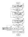
以上のように構成された光ビーコン車載装置1において、光ビーコン車載装置1がナビゲーション装置10から送られてきた大容量データを光ビーコン路上機20に送信するときのアップリンク方法について、図2および図3を用いて説明する。まず、光ビーコン車載装置1とナビゲーション装置10が動作し、ナビゲーション装置10において光ビーコン路上機20にアップリンクすべく種々のデータの集合体の大容量のデータ(例えば、現地点までの走行軌跡や速度、目的地情報など)が発生した場合に、ナビゲーション装置10は、ナビゲーションインターフェース部5を介して光ビーコン車載装置1にアップリンクデータを送り、光ビーコン車載装置1では、そのアップリンクデータをRAM8に記憶する(ステップS1)。その後、光ビーコン車載装置1が図2で示す光ビーコン路上機20の下に近づき(ステップS2)、光通信部9がアップリンク、ダウンリンクが可能な光の強さを検出すると、自車の車両IDを含む小容量のアップリンクデータ(例えば、旅行時間計測情報)を1回送信後、その小容量アップリンクデータに載せた自車の車両IDを含むダウンリンクデータ(1フレーム)を受信するため、光ビーコン路上機20での車両IDチェック時間とダウンリンクデータを1フレーム的確に受信できる最短の時間の合計の期間(例えば、3ms)をアップリンクせずに受信に専念する(ステップS3)。この受信に専念する期間に車両IDを含むダウンリンクデータを受信できない場合は、小容量のアップリンクデータ送信処理を繰り返す(ステップS4)。上記アップリンク、ダウンリンクが可能な光の強さとなる地点は、本来は図2の地点bからであるが、光の反射などによっては地点bの手前の領域Aでアップリンク、ダウンリンクが可能と判定することも考えられる。そこで、領域Aでアップリンクを行った場合に、ダウンリンクで自車の車両IDを受信できない場合は、複数サイクルの小容量データのアップリンクを行う。そして、小容量アップリンク後に車両IDが受信できた場合には、図2のその地点fは確実に領域Bであり、アップリンクが可能な領域であると判定し、前記ナビゲーション装置から受信した大容量のデータを以下のように車速に応じてアップリンクする。
In the optical beacon in-
図2の地点bの直前から小容量データをアップリンクした場合、小容量データアップリンクによりアップリンクが可能と判定した地点fは、地点bからアップリンク動作最大2サイクル後となり、この地点fを常に大容量データアップリンク開始地点とみなす。小容量アップリンクデータを20バイトとし、アップリンクの通信速度が64kbpsであれば、アップリンクに費やす時間は2.5msであり、自車の車両ID受信待ち時間3msと合わせて小容量データのアップリンクサイクルは5.5msとなり、よって地点fは領域Aの開始地点aから11msの地点となる。また、アップリンク領域Bの範囲は1.6mと決まっており、地点fでの車速を基に領域Bの終点の地点cまでの時間が算出でき、その時間が大容量データのアップリンク可能時間である。例えば、車速70km/hで地点fを通過したとすれば、領域Bは82msで通過することとなり、従って地点fからの大容量データのアップリンク可能時間は71ms(82ms−11ms)となり、光ビーコン規格最大の296バイトを4フレームに分割して送信するための時間(41ms)を確保することができる。 When small-capacity data is uplinked immediately before point b in FIG. 2, the point f at which it is determined that uplink is possible by the small-capacity data uplink is after a maximum of two cycles of uplink operation from point b. Always considered as the starting point for large data uplink. If the small-capacity uplink data is 20 bytes and the uplink communication speed is 64 kbps, the time spent on the uplink is 2.5 ms, and the small-capacity data is uploaded together with the vehicle ID reception waiting time of 3 ms. The link cycle is 5.5 ms. Therefore, the point f is 11 ms from the start point a of the area A. In addition, the range of the uplink area B is determined to be 1.6 m, the time to the end point c of the area B can be calculated based on the vehicle speed at the point f, and the time can be the uplink available time of the large-capacity data It is. For example, if the vehicle passes through the point f at a vehicle speed of 70 km / h, the region B passes through at 82 ms. Therefore, the uplink possible time for large-capacity data from the point f is 71 ms (82 ms-11 ms), and the optical beacon. It is possible to secure a time (41 ms) for dividing the standard maximum 296 bytes into four frames for transmission.
また、今後、規格の変更により現在より更に大きなデータをアップリンクするようになった場合、または、70km/hより速い車速で光ビーコン路上機20下を通過する場合、図2のf地点から領域Bの終点cまでにアップリンクすべきデータ全てを送信できない状況が発生する。そのため、地点fで車速を基に算出した大容量データのアップリンク可能時間からアップリンク可能なデータ量を算出し(ステップS5)、ナビゲーション装置10から受信しRAM8に記憶した大容量アップリンクデータのデータ量とを比較し、アップリンク可能時間内に全データが送信可能であると判定した場合には(ステップS6)、全データをアップリンクする(ステップS7)。一方、RAM8に記憶した大容量アップリンクデータのデータ量の方が大きい場合には、RAM8に記憶した大容量アップリンクデータ内で優先順位の高いデータ種別順にデータを選択し組み合わせて、上記したアップリンク可能なデータ長以内のアップリンクデータを作成してアップリンクを行う(ステップS8)。そして、アップリンク終了後の領域Cにおいてダウンリンクデータを受信し(ステップS9)、ナビゲーション装置10に送って表示する。
In the future, when the data change becomes higher than the present due to the change of the standard, or when passing under the optical
このように、本発明の実施の形態の光ビーコンを用いたアップリンク方法および光ビーコン車載装置によれば、大容量データのアップリンクの前に自車の車両IDを含む小容量データをアップリンクすることでアップリンク領域に入ったことを確実に知ることができ、かつアップリンク領域以内でアップリンクを終えることで、光ビーコン規格の最大長またはそれ以上のデータをアップリンクすることができ、かつアップリンク後の領域Cにおいてダウンリンクデータを的確に受信することができる。 Thus, according to the uplink method using the optical beacon and the optical beacon in-vehicle apparatus of the embodiment of the present invention, the small capacity data including the vehicle ID of the own vehicle is uplinked before the large capacity data uplink. By doing so, you can be sure that you have entered the uplink area, and by finishing the uplink within the uplink area, you can uplink the data of the maximum length of optical beacon standard or more, In addition, downlink data can be accurately received in the area C after the uplink.
次に、上記のステップS8において、車速別アップリンクデータ選択テーブル3を用いた場合の動作について説明する。図4は車速別アップリンクデータ選択テーブル3の詳細を示しており、図2の地点fでの車速を設定する車速項目X、車速項目の速度以下で地点
fを通過時に優先的にアップリンクすべきデータの種別情報を設定するアップリンクデータ種別項目Y、優先送信データ種別項目を基に作成したアップリンクデータを格納したR
AMアドレスを書き込むアップリンクデータ格納アドレス項目Zから構成されている。
Next, the operation when the uplink data selection table 3 by vehicle speed is used in step S8 will be described. FIG. 4 shows the details of the uplink data selection table 3 for each vehicle speed. The vehicle speed item X for setting the vehicle speed at the point f in FIG. 2 is preferentially uplinked when passing through the point f below the speed of the vehicle speed item. R that stores uplink data created based on the uplink data type item Y for setting the type information of the data to be transmitted and the priority transmission data type item
It consists of an uplink data storage address item Z for writing an AM address.
以上のように構成された車速別アップリンクデータ選択テーブル3を用いた場合のアップリンク方法について、図1、2を用いてその動作を説明する。まず、図4に示すような種別IDを持つアップリンクするデータの種類があるとする。また、車速項目Xとアップ
リンクデータ種別項目Yは事前にナビゲーション装置10から送られてきたデータを基に
設定したものである。そして、ナビゲーション装置10から大容量のアップリンクデータを受信すると、全ての車速に対してアップリンクデータ種別項目Yで指定されたデータ種
別のデータを優先順位の高い方から検索し、発見した順にデータを組み立て、各車速における地点fから地点cまでにアップリンク可能なデータ数以内のアップリンクデータの作成を行ってRAM8に格納し、各車速における格納データのアドレスをアップリンクデータ格納アドレス項目Zに格納する。その後、光ビーコン車載装置1が光ビーコン路上機2
0の領域へ進入し、地点fを通過した時の車速を検出し、例えば55km/hであれば60km/hのアップリンクデータ格納アドレスの項に格納されたアドレスで示されるデータのアップリンクを行う。
The operation of the uplink method using the vehicle speed-specific uplink data selection table 3 configured as described above will be described with reference to FIGS. First, assume that there is a type of uplink data having a type ID as shown in FIG. The vehicle speed item X and the uplink data type item Y are set based on data sent from the
The vehicle speed when entering the area 0 and passing through the point f is detected. For example, if it is 55 km / h, the uplink of the data indicated by the address stored in the 60 km / h uplink data storage address section is detected. Do.
このように、車速別アップリンクデータ選択テーブル3を用いることで、動的に優先順位付けした大容量データのアップリンクとダウンリンクデータの受信を的確に行うことができる。 In this way, by using the uplink data selection table 3 classified by vehicle speed, it is possible to accurately receive uplink and downlink data of large-capacity data dynamically prioritized.
なお、本実施の形態では、光ビーコン車載装置1にアップリンクデータおよび車速別送信優先順位データを送信する機器としてナビゲーション装置10を例に説明したが、光ビーコン車載装置と通信する機器はナビゲーション装置以外の車載装置または車外の装置でもかまわない。また、光ビーコン車載装置がデータを通信する方法は、1対1の通信であったり、LAN形式であってもまたは有線通信であっても無線通信であっても同様に実施可能である。
In the present embodiment, the
以上のように、本発明にかかる光ビーコンを用いたアップリンク方法および光ビーコン車載装置は、光ビーコン車載装置から大容量のデータを光ビーコン路上機へアップリンクする際、光ビーコン車載装置から自車の車両IDを含む小容量のデータをアップリンクした後、光ビーコン路上機からのダウンリンクデータにアップリンクデータ受信済みのデータを確認することができた場合には、そのときの車速に対応した大きさのデータをアップリンクすることにより、大容量データのアップリンクとダウンリンクデータの受信を的確に行うことができるという効果を有し、VICSにおける光ビーコン車載装置に用いられるアップリンクデータを光ビーコン路上機に送信する方等として有用である。 As described above, the uplink method using the optical beacon and the optical beacon in-vehicle apparatus according to the present invention are automatically transmitted from the optical beacon in-vehicle apparatus when uplinking a large amount of data from the optical beacon in-vehicle apparatus to the optical beacon roadside device. After uplinking a small amount of data including the vehicle ID of the car, if the uplink data received data can be confirmed in the downlink data from the optical beacon roadside device, it corresponds to the vehicle speed at that time By uplinking the data of the specified size, there is an effect that it is possible to accurately receive large-capacity data uplink and downlink data. It is useful as a method of transmitting to an optical beacon roadside machine.
1 光ビーコン車載装置
2 EPU
3 車速別アップリンクデータ選択テーブル
4 LED&フォトセンサ
5 ナビゲーションインターフェース部
6 CPU
7 ROM
8 RAM
9 光通信部
10 ナビゲーション装置
20 光ビーコン路上機
A 光ビーコン路上機の光の強さが受信可能な強さとなる可能性のある領域
B 光ビーコン路上機と送受信が可能である領域
C 光ビーコン路上機から受信のみ可能である領域
a 光ビーコン路上機の光の強さが受信可能な強さとなる可能性のある領域の開始地点 b 光ビーコン路上機と送受信が可能である領域の開始地点
c 光ビーコン路上機から受信のみが可能である領域の開始地点
d 光ビーコン路上機から受信のみが可能である領域の終了地点
e 地点aの1ms手前から236バイトのデータをアップリンク後車両ID待ち時間(3ms)が経過した地点
f 地点aから小容量データのアップリンクと車両ID待ちを2サイクル行った地点
X 車速項目
Y アップリンクデータ種別項目
Z アップリンクデータ格納アドレス項目
1 Optical beacon in-
3 Uplink data selection table by
7 ROM
8 RAM
9
X Vehicle speed item
Y Uplink data type item
Z Uplink data storage address item
Claims (2)
Priority Applications (1)
| Application Number | Priority Date | Filing Date | Title |
|---|---|---|---|
| JP2004074701A JP4597555B2 (en) | 2004-03-16 | 2004-03-16 | Uplink method using optical beacon and optical beacon in-vehicle device |
Applications Claiming Priority (1)
| Application Number | Priority Date | Filing Date | Title |
|---|---|---|---|
| JP2004074701A JP4597555B2 (en) | 2004-03-16 | 2004-03-16 | Uplink method using optical beacon and optical beacon in-vehicle device |
Publications (2)
| Publication Number | Publication Date |
|---|---|
| JP2005268925A JP2005268925A (en) | 2005-09-29 |
| JP4597555B2 true JP4597555B2 (en) | 2010-12-15 |
Family
ID=35093045
Family Applications (1)
| Application Number | Title | Priority Date | Filing Date |
|---|---|---|---|
| JP2004074701A Expired - Fee Related JP4597555B2 (en) | 2004-03-16 | 2004-03-16 | Uplink method using optical beacon and optical beacon in-vehicle device |
Country Status (1)
| Country | Link |
|---|---|
| JP (1) | JP4597555B2 (en) |
Families Citing this family (25)
| Publication number | Priority date | Publication date | Assignee | Title |
|---|---|---|---|---|
| JP4802735B2 (en) * | 2006-01-27 | 2011-10-26 | 住友電気工業株式会社 | Distance calculation device, distance calculation method, and vehicle having the device |
| JP2007264825A (en) * | 2006-03-27 | 2007-10-11 | Kenwood Corp | Information providing system, information providing apparatus, on-vehicle apparatus, and method of providing information |
| JP5034421B2 (en) * | 2006-10-02 | 2012-09-26 | 住友電気工業株式会社 | Road-to-vehicle communication system and method, and optical beacon, in-vehicle device and vehicle used therefor |
| JP4670788B2 (en) * | 2006-10-23 | 2011-04-13 | 住友電気工業株式会社 | Road-to-vehicle communication system and method, and optical beacon, in-vehicle device and vehicle used therefor |
| JP4835381B2 (en) * | 2006-10-23 | 2011-12-14 | 住友電気工業株式会社 | Road-to-vehicle communication determination system and method, determination apparatus and vehicle-mounted device used therefor |
| JP4835393B2 (en) * | 2006-11-06 | 2011-12-14 | 住友電気工業株式会社 | Road-to-vehicle communication determination system and method, and determination device used therefor |
| CN101636772B (en) * | 2006-12-15 | 2012-07-11 | 株式会社建伍 | Mobile body position information transmitting device for navigation system, and mobile body position information transmission method for navigation system |
| JP4861839B2 (en) * | 2007-01-23 | 2012-01-25 | 富士通株式会社 | POSITION LOCATION DEVICE, POSITION LOCATION METHOD, INFORMATION DISTRIBUTION DEVICE, AND INFORMATION DISTRIBUTION METHOD |
| JP4687669B2 (en) * | 2007-03-14 | 2011-05-25 | 住友電気工業株式会社 | Distance recognition system, optical beacon, in-vehicle device, and distance recognition method |
| JP4946567B2 (en) * | 2007-03-28 | 2012-06-06 | 住友電気工業株式会社 | Light beacon |
| JP4972807B2 (en) * | 2007-07-11 | 2012-07-11 | 本田技研工業株式会社 | In-vehicle optical beacon device |
| JP4924354B2 (en) * | 2007-10-16 | 2012-04-25 | 株式会社デンソー | Optical beacon in-vehicle communication device |
| JP4698699B2 (en) * | 2008-04-07 | 2011-06-08 | 三菱電機株式会社 | Road-to-vehicle information communication processing in-vehicle device |
| JP2009272902A (en) * | 2008-05-08 | 2009-11-19 | Sumitomo Electric Ind Ltd | Light reception circuit, optical beacon having the same, and on-vehicle machine |
| JP5056815B2 (en) * | 2009-08-20 | 2012-10-24 | 住友電気工業株式会社 | Road-to-vehicle communication method, road-to-vehicle communication system, in-vehicle device, and vehicle |
| JP4687817B2 (en) * | 2009-08-20 | 2011-05-25 | 住友電気工業株式会社 | Road-to-vehicle communication system and optical beacon |
| JP5766924B2 (en) * | 2010-09-13 | 2015-08-19 | 三菱電機株式会社 | In-vehicle device, approach time calculation method, and approach time calculation program |
| JP5966458B2 (en) * | 2011-12-13 | 2016-08-10 | 住友電気工業株式会社 | Road-to-vehicle communication system and optical beacon |
| JP5980658B2 (en) * | 2012-07-09 | 2016-08-31 | 住友電工システムソリューション株式会社 | Light beacon |
| JP5300107B1 (en) * | 2012-08-08 | 2013-09-25 | 住友電工システムソリューション株式会社 | Light beacon |
| JP6229519B2 (en) * | 2014-02-06 | 2017-11-15 | 株式会社デンソー | Road-to-vehicle communication system |
| JP6557932B2 (en) * | 2015-09-24 | 2019-08-14 | パナソニックIpマネジメント株式会社 | On-vehicle device, road-to-vehicle communication system, and uplink method |
| JP2017092891A (en) * | 2015-11-17 | 2017-05-25 | 住友電工システムソリューション株式会社 | Optical beacon |
| JP2017092879A (en) * | 2015-11-17 | 2017-05-25 | 住友電工システムソリューション株式会社 | Optical beacon |
| CN111739282A (en) * | 2019-03-25 | 2020-10-02 | 姚琴 | Method, system and device for identifying no-parking area based on interactive beacon |
Citations (11)
| Publication number | Priority date | Publication date | Assignee | Title |
|---|---|---|---|---|
| JPH08190694A (en) * | 1995-01-10 | 1996-07-23 | Nippondenso Co Ltd | Traffic information receiver |
| JPH08202987A (en) * | 1995-01-27 | 1996-08-09 | Nippondenso Co Ltd | Optical on-vehicle communication equipment |
| JPH09134494A (en) * | 1995-11-08 | 1997-05-20 | Matsushita Electric Ind Co Ltd | On-vehicle optical beacon device |
| JPH09312617A (en) * | 1996-05-20 | 1997-12-02 | Sharp Corp | On-vehicle optical beacon transmitter-receiver |
| JPH10200477A (en) * | 1997-01-14 | 1998-07-31 | Mitsubishi Electric Corp | Optical transmitter-receiver |
| JPH10332803A (en) * | 1997-05-28 | 1998-12-18 | Fujitsu Ten Ltd | Data output device of vics vehicle-mounted light beacon device |
| JP2002296110A (en) * | 2001-03-30 | 2002-10-09 | Hitachi Kokusai Electric Inc | Optical level monitoring device |
| JP2003284115A (en) * | 2002-03-27 | 2003-10-03 | Natl Inst For Land & Infrastructure Management Mlit | Hand-over system |
| JP2003317188A (en) * | 2002-04-25 | 2003-11-07 | Yamaha Corp | Information service providing system |
| JP2004006710A (en) * | 2002-03-15 | 2004-01-08 | Fitel Usa Corp | Wavelength variable multi-mode laser diode module, variable wavelength wavelength division multiplex raman pump and amplifier, system, method and computer program product for controlling variable wavelength multimode laser diode, raman pump and raman amplifier |
| JP2004535073A (en) * | 2001-07-09 | 2004-11-18 | コーニング インコーポレイテッド | Control architecture and control method of optical amplifier |
-
2004
- 2004-03-16 JP JP2004074701A patent/JP4597555B2/en not_active Expired - Fee Related
Patent Citations (11)
| Publication number | Priority date | Publication date | Assignee | Title |
|---|---|---|---|---|
| JPH08190694A (en) * | 1995-01-10 | 1996-07-23 | Nippondenso Co Ltd | Traffic information receiver |
| JPH08202987A (en) * | 1995-01-27 | 1996-08-09 | Nippondenso Co Ltd | Optical on-vehicle communication equipment |
| JPH09134494A (en) * | 1995-11-08 | 1997-05-20 | Matsushita Electric Ind Co Ltd | On-vehicle optical beacon device |
| JPH09312617A (en) * | 1996-05-20 | 1997-12-02 | Sharp Corp | On-vehicle optical beacon transmitter-receiver |
| JPH10200477A (en) * | 1997-01-14 | 1998-07-31 | Mitsubishi Electric Corp | Optical transmitter-receiver |
| JPH10332803A (en) * | 1997-05-28 | 1998-12-18 | Fujitsu Ten Ltd | Data output device of vics vehicle-mounted light beacon device |
| JP2002296110A (en) * | 2001-03-30 | 2002-10-09 | Hitachi Kokusai Electric Inc | Optical level monitoring device |
| JP2004535073A (en) * | 2001-07-09 | 2004-11-18 | コーニング インコーポレイテッド | Control architecture and control method of optical amplifier |
| JP2004006710A (en) * | 2002-03-15 | 2004-01-08 | Fitel Usa Corp | Wavelength variable multi-mode laser diode module, variable wavelength wavelength division multiplex raman pump and amplifier, system, method and computer program product for controlling variable wavelength multimode laser diode, raman pump and raman amplifier |
| JP2003284115A (en) * | 2002-03-27 | 2003-10-03 | Natl Inst For Land & Infrastructure Management Mlit | Hand-over system |
| JP2003317188A (en) * | 2002-04-25 | 2003-11-07 | Yamaha Corp | Information service providing system |
Also Published As
| Publication number | Publication date |
|---|---|
| JP2005268925A (en) | 2005-09-29 |
Similar Documents
| Publication | Publication Date | Title |
|---|---|---|
| JP4597555B2 (en) | Uplink method using optical beacon and optical beacon in-vehicle device | |
| JP5040429B2 (en) | COMMUNICATION SYSTEM, ROAD SIDE COMMUNICATION SYSTEM, ROAD SIDE COMMUNICATION DEVICE, OPTICAL BEACON, AND IN-VEHICLE COMMUNICATION DEVICE | |
| JP4356751B2 (en) | Communication device | |
| US20100299001A1 (en) | Vehicle communication terminal and vehicle communication system in which radio transmissions by the vehicle communication terminals are controlled by radio communication from base stations | |
| WO2016024385A1 (en) | Information-processing system, terminal device, program, handheld terminal device, and non-transitory, tangible, computer-readable recording medium | |
| JP3150644B2 (en) | Data output device for VICS on-board optical beacon device | |
| JP4972807B2 (en) | In-vehicle optical beacon device | |
| JP2009232065A (en) | Communication system, and on-board communication device | |
| JP2009258938A (en) | Traffic congestion information acquisition system and traffic congestion information acquisition method | |
| US10946857B2 (en) | Geotagged and time stamped data secured by digital signature shared on private network | |
| JP2007304836A (en) | On-vehicle information presentation device and program | |
| JP6387744B2 (en) | On-board device and driving support system | |
| JP6565768B2 (en) | Optical communication device | |
| JP2006059250A (en) | Vics on-road equipment and vics on-road equipment communication method | |
| JP2006072936A (en) | Vehicle stoppage requiring system | |
| JP2011044002A (en) | Inter-vehicle communication apparatus for vehicle | |
| JP6670984B1 (en) | Wireless communication system, base station, mobile station, and wireless communication method | |
| JP2000311286A (en) | Traffic control system | |
| JP7095548B2 (en) | Driving support system | |
| JP6960956B2 (en) | On-board unit, road-to-vehicle communication system using it, and roadside unit information notification method | |
| JPH11355212A (en) | Optical beacon transmission reception equipment | |
| JP5471218B2 (en) | Road-to-vehicle communication system and in-vehicle device | |
| JP2007293660A (en) | Optical beacon, road-vehicle communication system, on-vehicle device used for the system, and distance recognition method using the system | |
| JP4924507B2 (en) | Driving assistance device | |
| JP2009017204A (en) | Communication system, optical beacon, and onboard communication apparatus |
Legal Events
| Date | Code | Title | Description |
|---|---|---|---|
| A621 | Written request for application examination |
Free format text: JAPANESE INTERMEDIATE CODE: A621 Effective date: 20060913 |
|
| A977 | Report on retrieval |
Free format text: JAPANESE INTERMEDIATE CODE: A971007 Effective date: 20081030 |
|
| A131 | Notification of reasons for refusal |
Free format text: JAPANESE INTERMEDIATE CODE: A131 Effective date: 20081104 |
|
| A521 | Request for written amendment filed |
Free format text: JAPANESE INTERMEDIATE CODE: A523 Effective date: 20081204 |
|
| A131 | Notification of reasons for refusal |
Free format text: JAPANESE INTERMEDIATE CODE: A131 Effective date: 20100105 |
|
| A521 | Request for written amendment filed |
Free format text: JAPANESE INTERMEDIATE CODE: A523 Effective date: 20100303 |
|
| TRDD | Decision of grant or rejection written | ||
| A01 | Written decision to grant a patent or to grant a registration (utility model) |
Free format text: JAPANESE INTERMEDIATE CODE: A01 Effective date: 20100907 |
|
| A01 | Written decision to grant a patent or to grant a registration (utility model) |
Free format text: JAPANESE INTERMEDIATE CODE: A01 |
|
| A61 | First payment of annual fees (during grant procedure) |
Free format text: JAPANESE INTERMEDIATE CODE: A61 Effective date: 20100922 |
|
| R150 | Certificate of patent or registration of utility model |
Ref document number: 4597555 Country of ref document: JP Free format text: JAPANESE INTERMEDIATE CODE: R150 Free format text: JAPANESE INTERMEDIATE CODE: R150 |
|
| FPAY | Renewal fee payment (event date is renewal date of database) |
Free format text: PAYMENT UNTIL: 20131001 Year of fee payment: 3 |
|
| LAPS | Cancellation because of no payment of annual fees |