JP2017013640A - On-vehicle information apparatus - Google Patents
On-vehicle information apparatus Download PDFInfo
- Publication number
- JP2017013640A JP2017013640A JP2015132719A JP2015132719A JP2017013640A JP 2017013640 A JP2017013640 A JP 2017013640A JP 2015132719 A JP2015132719 A JP 2015132719A JP 2015132719 A JP2015132719 A JP 2015132719A JP 2017013640 A JP2017013640 A JP 2017013640A
- Authority
- JP
- Japan
- Prior art keywords
- vehicle
- information device
- vehicle information
- current
- detection signal
- Prior art date
- Legal status (The legal status is an assumption and is not a legal conclusion. Google has not performed a legal analysis and makes no representation as to the accuracy of the status listed.)
- Granted
Links
Images
Abstract
Description
この発明は、盗難防止機構を有した車載情報機器に関する。 The present invention relates to an in-vehicle information device having an anti-theft mechanism.
例えば、特許文献1には、車両のダッシュボードなどに取り付けられる車両用盗難防止装置が記載されている。この装置では、制御部と警報を発生する警報器がダッシュボードの裏側に取り付けられ、操作部がダッシュボード上に取り付けられている。この操作部と制御部とは車室内に一部が露出した制御線によって接続されており、制御部と警報器とは警報線によって接続されている。この構成において、操作部が動かされて制御線が切断されると、ダッシュボードの裏側の警報器が警報を発生するようになっている。 For example, Patent Document 1 describes a vehicle antitheft device attached to a dashboard of a vehicle. In this device, a control unit and an alarm that generates an alarm are attached to the back side of the dashboard, and an operation unit is attached to the dashboard. The operation unit and the control unit are connected by a control line that is partially exposed in the vehicle interior, and the control unit and the alarm device are connected by an alarm line. In this configuration, when the operation unit is moved and the control line is cut, the alarm device on the back side of the dashboard generates an alarm.
従来の技術では、特許文献1に記載される制御線のように盗難の検知機構が何らかの形で外部に露出しており、盗難の検知機構と装置自体の取り付け構造とが無関係であった。
このため、外部から細工を加えることによって盗難の検知機構が無効化される可能性があるという課題があった。例えば、特許文献1に記載される装置では、操作部および制御部の取り付け構造と盗難の検知機構とが無関係であり、制御線による接続を維持したまま操作部と制御部の双方を取り外せば、警報を鳴らさずに車外に持ち運ぶことができる。
また、従来の盗難防止装置は、警報を発生させるブザーなどの専用の出力装置が必要な場合が多く、この場合、出力装置の分の寸法的またはコスト的な制約が常に生じていた。
In the prior art, the theft detection mechanism is exposed to the outside in some form, like the control line described in Patent Document 1, and the theft detection mechanism and the mounting structure of the device itself are irrelevant.
For this reason, there has been a problem that the theft detection mechanism may be invalidated by adding work from the outside. For example, in the apparatus described in Patent Document 1, the attachment structure of the operation unit and the control unit and the theft detection mechanism are irrelevant, and if both the operation unit and the control unit are removed while maintaining the connection by the control line, Can be carried outside the vehicle without sounding an alarm.
In addition, the conventional antitheft device often requires a dedicated output device such as a buzzer for generating an alarm, and in this case, there are always dimensional or cost restrictions for the output device.
この発明は上記の課題を解決するもので、盗難の検知機構が悟られにくい車載情報機器を得ることを目的とする。 The present invention solves the above-described problems, and an object thereof is to obtain an in-vehicle information device in which a theft detection mechanism is difficult to understand.
この発明に係る車載情報機器は、電流検知部と制御部を備える。電流検知部は、車両に車載情報機器を取り付けたときに形成される第1の電流経路から、車載情報機器の取り外しによって第1の電流経路とは異なる第2の電流経路に経路変化した暗電流を検知して検知信号を出力する。制御部は、電流検知部から検知信号を入力すると、警報情報を出力部に出力させる。 The in-vehicle information device according to the present invention includes a current detection unit and a control unit. The current detection unit is a dark current that is changed from a first current path formed when the in-vehicle information device is attached to the vehicle to a second current path different from the first current path by removing the in-vehicle information device. Is detected and a detection signal is output. When the control unit inputs a detection signal from the current detection unit, the control unit causes the output unit to output alarm information.
この発明によれば、車両からの取り外しで電流経路が変化した暗電流を用いて検知信号を出力するので、盗難の検知機構が悟られにくい車載情報機器を実現することができる。 According to the present invention, since the detection signal is output using the dark current whose current path has been changed by being removed from the vehicle, it is possible to realize an in-vehicle information device in which the theft detection mechanism is difficult to understand.
実施の形態1.
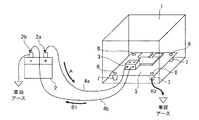
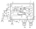
図1は、この発明の実施の形態1に係る車載情報機器1の概要を示す図である。なお、図1において、車載情報機器1の筐体から内部構成がみえるように記載している。
車載情報機器1は、バッテリ2から電力が供給されて各種の情報処理を実施する車載用の情報機器であり、例えば、ナビゲーション装置、オーディオ装置などで具体化することができる。また、車載情報機器1には、電源オフの状態であってもメモリにデータを保持するために数mA程度の微弱な電流(以下、暗電流と記載する)が流れている。
バッテリ2の電流は、プラス端子2aから電源ケーブル4aとコネクタ3を通る往路Aで基板5の回路に供給され、帰路B1および帰路B2のうち、抵抗値の低い帰路を通ってバッテリ2に戻る。
Embodiment 1 FIG.
FIG. 1 is a diagram showing an outline of an in-vehicle information device 1 according to Embodiment 1 of the present invention. In FIG. 1, it is described so that the internal configuration can be seen from the housing of the in-vehicle information device 1.
The in-vehicle information device 1 is an in-vehicle information device that is supplied with power from the
The current of the
帰路B1は、この発明における第2の電流経路に相当するものであり、コネクタ3から電源ケーブル4bを通ってマイナス端子2bへ向かう電流経路である。
帰路B2は、この発明における第1の電流経路に相当するものであり、基板5のアースから基板取り付け部6,7および車両アースを通ってマイナス端子2bへ向かう電流経路である。
The return path B1 corresponds to the second current path in the present invention, and is a current path from the
The return path B2 corresponds to the first current path in the present invention, and is a current path from the ground of the
基板取り付け部6,7は、車載情報機器1の筐体内に基板5を取り付ける導電性の部材である。例えば、基板取り付け部6は、金属製のねじとして実現され、基板取り付け部7は、ねじ台座となる金属製のボスとして実現される。なお、基板5のアースは、基板取り付け部6,7と電気的に接続している。
The
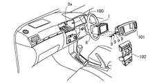
図2は、実施の形態1に係る車載情報機器1のダッシュボードへの取り付けを示す図である。車載情報機器1は、ダッシュボードの取り付け部100に取り付けられる。
取り付け部100に設けられたコネクタ3aは、図1に示した電源ケーブル4a,4bを介してバッテリ2に接続している。すなわち、コネクタ3aは、コネクタ3を構成する一方のコネクタである。車載情報機器1の筐体には、ブラケット8が取り付けられる。
ブラケット8は、板金などの導電性の部材で形成され、車載情報機器1の筐体を介して基板取り付け部6,7と電気的に接続している。これにより、基板5のアースは、ブラケット8と導通する。
FIG. 2 is a diagram illustrating attachment of the in-vehicle information device 1 according to the first embodiment to the dashboard. The in-vehicle information device 1 is attached to a
The
The
車載情報機器1を取り付け部100に取り付ける場合、まず、コネクタ3aを車載情報機器1に接続してから取り付け部100に挿入する。この後、ビス9で取り付け部100にブラケット8を固定してから、化粧パネル101,102を取り付ける手順となる。
なお、ビス9で車載情報機器1の筐体を直接取り付け部100に固定してもよい。
このように車載情報機器1を取り付けることにより、基板5のアースは、基板取り付け部6,7、筐体、ブラケット8およびビス9を介して車両アースと電気的に接続される。
When attaching the in-vehicle information device 1 to the
Note that the housing of the in-vehicle information device 1 may be directly fixed to the
By mounting the in-vehicle information device 1 in this way, the ground of the
車載情報機器1を取り付け部100から取り外す場合、化粧パネル101,102を取り外した後にビス9を外して車載情報機器1を引き出し、コネクタ3aを抜くという手順となる。従って、車載情報機器1を取り外した状態では、図1で示した帰路B2が切断されて基板5のアースと車両アースとの電気的な接続が切断される。
When detaching the in-vehicle information device 1 from the
この発明では、車載情報機器1が取り付けられた状態で帰路B2に暗電流を流し、車載情報機器1の取り外しで帰路B2が切断されて帰路B1に暗電流が経路変化すると、警報を出力する。このように盗難の検知機構と車載情報機器の取り付け構造が関連付けられているため、外部から細工を加えることが困難で盗難の検知機構が無効化されにくい。 In the present invention, when the vehicle information device 1 is attached, a dark current is caused to flow through the return path B2, and when the vehicle information device 1 is removed and the return path B2 is disconnected and the dark current changes the path to the return route B1, an alarm is output. As described above, since the theft detection mechanism and the mounting structure of the in-vehicle information device are associated with each other, it is difficult to add work from the outside, and the theft detection mechanism is difficult to be invalidated.
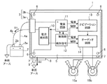
図3は、実施の形態1に係る車載情報機器1の構成を示すブロック図であり、車載情報機器1をオーディオ一体型のナビゲーション装置として具体化した場合を示している。
図3に示すように、コネクタ3aは、車載情報機器1に設けられたコネクタ3bに嵌合して車載情報機器1とバッテリ2とを接続している。
車載情報機器1は、電流検知部10、電源回路11、制御部12、ナビゲーション回路13およびオーディオ回路14を備えており、基板5のアースは、基板取り付け部6,7とブラケット8とビス9を介して車両アースに接続されている。
FIG. 3 is a block diagram showing the configuration of the in-vehicle information device 1 according to the first embodiment, and shows a case where the in-vehicle information device 1 is embodied as an audio integrated navigation device.
As shown in FIG. 3, the
The in-vehicle information device 1 includes a
電流検知部10は、車両に車載情報機器1を取り付けたときに形成される帰路B2から車載情報機器1の取り外しによって帰路B1に経路変化した暗電流を検知する。電流検知部10による検知信号は、制御部12に出力される。
電源回路11は、電源ケーブル4a,4bとコネクタ3を介して接続されたバッテリ2から電力を受けて、制御部12、ナビゲーション回路13、オーディオ回路14に対して電源を供給する。
The
The
制御部12は、ナビゲーション回路13とオーディオ回路14の各動作を制御する制御部である。また、制御部12は、この発明に特有な動作として、電流検知部10から検知信号を入力すると、ナビゲーション回路13およびオーディオ回路14を制御してスピーカ15a,15bなどの出力部から警報情報を出力させる。
ナビゲーション回路13は、地図表示、経路探索、経路案内などのナビゲーション処理を実行する回路である。オーディオ回路14は、音声信号をスピーカ15a,15bから出力させる回路である。
The
The
また、ナビゲーション回路13は、経路案内の音声ガイダンスを生成する音声出力処理部としても機能する。音声出力処理部は、オーディオ回路14に指示して音声ガイダンスをスピーカ15a,15bから出力させるものである。
なお、スピーカ15a,15bは、車両に標準的に装備された車両スピーカである。
The
Note that the
次に、電流検知部10の具体例を挙げて、本発明における盗難検知の概要を説明する。
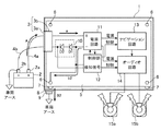
図4は、実施の形態1に係る車載情報機器1の取り付け状態における電流経路を示す図である。また、図5は、実施の形態1に係る車載情報機器1の取り外し状態における電流経路を示す図である。図4、図5において、電流検知部10は、ダイオードD1,D2とトランジスタTRとを備えて構成される。
Next, the outline of theft detection in the present invention will be described by giving a specific example of the
FIG. 4 is a diagram illustrating a current path in the mounted state of the in-vehicle information device 1 according to the first embodiment. FIG. 5 is a diagram illustrating a current path in a detached state of the in-vehicle information device 1 according to the first embodiment. 4 and 5, the
ダイオードD1,D2は、ダイオードD2のアノード端子にダイオードD1のカソード端子が接続されており、車載情報機器1が車両に取り付けられた状態で暗電流が帰路B2を流れ、車載情報機器1が取り外されると暗電流が帰路B1に流れるように配置される。
すなわち、ダイオードD2のカソード端子は、コネクタ3と電源ケーブル4bを介してバッテリ2のマイナス端子2bに接続し、ダイオードD1のアノード端子は、電源回路11のマイナス端子に接続している。これにより、ダイオードD1,D2は帰路B1の途中に介在することになる。
In the diodes D1 and D2, the cathode terminal of the diode D1 is connected to the anode terminal of the diode D2, and the dark current flows through the return path B2 with the in-vehicle information device 1 attached to the vehicle, and the in-vehicle information device 1 is removed. And the dark current is arranged to flow in the return path B1.
That is, the cathode terminal of the diode D2 is connected to the
車両に車載情報機器1が取り付けられた状態において、バッテリ2からの電流は、図4に矢印aで示すように、プラス端子2aから電源ケーブル4aとコネクタ3を介して電源回路11のプラス端子へ流れる。そして、電源回路11のマイナス端子からバッテリ2に戻る経路は帰路B1と帰路B2の2つがあるが、帰路B1は、ダイオードD1,D2の順方向電圧が発生する経路である。このため、帰路B1、帰路B2とも接続されている状態では、図4に矢印b2で示すように暗電流は帰路B2のみに流れ、図5に矢印b1で示すように車載情報機器1が取り外され帰路B2が遮断された場合に限り、暗電流は帰路B1に流れることになる。
In the state where the vehicle-mounted information device 1 is attached to the vehicle, the current from the
電流検知部10は、帰路B1に電流が流れたとき、すなわち車載情報機器1が車両から取り外されたときに、これを検知し、検知信号を制御部12に出力する。例えば、ダイオードD1,D2の順方向電圧を検知信号として制御部12に出力する。暗電流が帰路B2を流れる場合、順方向電圧は0Vである。一方、帰路B2が遮断されて暗電流が帰路B1を流れる場合、ダイオードD1,D2の各順方向電圧が0.7Vであると、制御部12には、0.7+0.7=1.4Vの順方向電圧が検知信号として印加される。これにより、制御部12は、車載情報機器1の取り外しを認識することができる。
このようにダイオードD1,D2といった安価な部品を追加するだけで電流検知部10を実現することができる。
The
In this way, the
また、ダイオードD1,D2の順方向電圧の検知には、例えばバイポーラトランジスタTRを用いてもよい。この場合、トランジスタTRのベース端子は、抵抗Rを介して電源回路11のマイナス端子に接続し、エミッタ端子は、ダイオードD2のカソード端子に接続し、コレクタ端子は、制御部12の検知信号入力端子に接続する。
帰路B2が遮断されて暗電流が帰路B1を流れた場合、ダイオードD1,D2の両端に順方向電圧が発生してトランジスタTRはオンとなり、検知信号が制御部12に入力される。このように構成しても、ダイオードD1,D2、トランジスタTRといった安価な部品を追加するだけで電流検知部10を実現することができる。
なお、ダイオードD1,D2の順方向電圧を検知する方法は、トランジスタ以外にも、例えば、ロジックIC、コンパレータ、A/Dコンバータなどを用いてもよい。
Further, for example, a bipolar transistor TR may be used for detecting the forward voltage of the diodes D1 and D2. In this case, the base terminal of the transistor TR is connected to the negative terminal of the
When the return path B2 is interrupted and a dark current flows through the return path B1, a forward voltage is generated at both ends of the diodes D1 and D2, the transistor TR is turned on, and a detection signal is input to the
As a method for detecting the forward voltage of the diodes D1 and D2, a logic IC, a comparator, an A / D converter, or the like may be used in addition to the transistor.
電流検知部10から制御部12へ検知信号を入力すると、制御部12は、電源回路11に指示してナビゲーション回路13とオーディオ回路14に電源を供給する。
次に、制御部12は、音声出力処理部として機能するナビゲーション回路13に指示して、警報情報を生成させる。なお、警報情報は、ブザー音などの警報音でもよいが、車両から車載情報機器1が不正に取り外されたことを示す警告音声であってもよい。
オーディオ回路14は、ナビゲーション回路13によって生成された警報情報を、スピーカ15a,15bから出力させる。このようにして、スピーカ15a,15bから警報音が吹鳴される。
When a detection signal is input from the
Next, the
The
車両には、ナビゲーション装置、オーディオ機器などの車載情報機器の音声出力に使用されるスピーカが標準的に搭載されている場合が多い。このようなスピーカであっても、その音量によっては車外に音を届かせることができる。
従って、制御部12が、ナビゲーション回路13、オーディオ回路14およびスピーカ15a,15bを警報器として利用することで、警報専用の装置を新たに追加する必要がない。これにより、専用装置の追加で生じる寸法的またはコスト的な制約を軽減することができる。
In many cases, a vehicle is normally equipped with a speaker that is used for outputting sound of in-vehicle information devices such as navigation devices and audio devices. Even with such a speaker, the sound can reach outside the vehicle depending on its volume.
Therefore, the
また、車載情報機器1が、通信ネットワークを介して他の通信装置との間で無線通信を行う通信処理部を備えている場合、制御部12が、この通信処理部に指示して、予め定められた通知先の装置に警報情報を送信させてもよい。例えば、予め定められたアドレスの通信装置に対して、盗難されたことを示す警告情報の電子メールを送信してもよく、予め定められた電話番号の電話に繋いで警告音声の合成音を送信してもよい。
このようにすることで、車載情報機器の所有者などに対して盗難にあったことを的確に伝えることができる。
In addition, when the in-vehicle information device 1 includes a communication processing unit that performs wireless communication with another communication device via a communication network, the
By doing so, it is possible to accurately tell the owner of the in-vehicle information device that the theft has been made.
さらに、制御部12が、電流検知部10から検知信号を入力すると、車両に搭載されたドライブレコーダに対して車載情報機器1が取り外されたときの状況を記録してもよい。
このように構成することで、ドライブレコーダの記録内容から車載情報機器が盗難された日時、状態などの状況を認識することができ、これらの情報を盗難後の処理に役立てることができる。
Further, when the
By configuring in this way, it is possible to recognize the situation such as the date and state when the in-vehicle information device is stolen from the recorded contents of the drive recorder, and it is possible to use this information for processing after the theft.
以上のように、実施の形態1に係る車載情報機器1は、電流検知部10と制御部12を備える。電流検知部10は、車載情報機器1を取り付けたときに形成される帰路B2から車載情報機器1の取り外しによって帰路B1に経路変化した暗電流を検知して検知信号を出力する。制御部12は、電流検知部10から検知信号を入力すると、警報音をスピーカ15a,15bに出力させる。
このように車載情報機器1の取り外しで電流経路が変化した暗電流を用いて検知信号を出力するので、盗難の検知機構が悟られにくい車載情報機器1を実現することができる。
As described above, the in-vehicle information device 1 according to the first embodiment includes the
As described above, since the detection signal is output using the dark current whose current path is changed by removing the in-vehicle information device 1, the in-vehicle information device 1 in which the theft detection mechanism is difficult to be realized can be realized.
また、実施の形態1に係る車載情報機器1において、制御部12は、電流検知部10から検知信号を入力すると、ナビゲーション回路13あるいはオーディオ回路14に指示してスピーカ15a,15bから警報情報を出力させる。このように構成することで、専用装置の追加で生じる寸法的またはコスト的な制約を軽減することができる。
In the in-vehicle information device 1 according to the first embodiment, when the
さらに、実施の形態1に係る車載情報機器1において、電流検知部10は、帰路B2から車載情報機器1の取り外しによって暗電流の経路が帰路B1に変わると、順方向電圧が発生するダイオードD1,D2を備える。電流検知部10は、ダイオードD1,D2の順方向電圧を検知すると検知信号として制御部12に出力する。
このように構成することで、ダイオードD1,D2といった安価な部品を追加するだけで電流検知部10を実現することができる。
Furthermore, in the in-vehicle information device 1 according to the first embodiment, the
With such a configuration, the
さらに、実施の形態1に係る車載情報機器1において、制御部12は、電流検知部10から検知信号を入力すると、通信処理部に指示して警報情報を予め定められた通知先に送信する。このようにすることで、車載情報機器の所有者などに対して盗難にあったことを的確に伝えることができる。
Furthermore, in the in-vehicle information device 1 according to Embodiment 1, when the
さらに、実施の形態1に係る車載情報機器1において、制御部12は、電流検知部10から検知信号を入力すると、車両に搭載されたドライブレコーダに対して車載情報機器1が取り外されたときの状況を記録する。このようにすることで、ドライブレコーダの記録内容から車載情報機器が盗難された日時、状態などの状況を認識することができ、これらの情報を盗難後の処理に役立てることができる。
Furthermore, in the in-vehicle information device 1 according to the first embodiment, when the
なお、本発明はその発明の範囲内において、実施の形態の任意の構成要素の変形、もしくは実施の形態の任意の構成要素の省略が可能である。 In the present invention, any component of the embodiment can be modified or any component of the embodiment can be omitted within the scope of the invention.
1 車載情報機器、2 バッテリ、2a プラス端子、2b マイナス端子、3,3a,3b コネクタ、4a,4b 電源ケーブル、5 基板、6,7 基板取り付け部、8 ブラケット、9 ビス、10 電流検知部、11 電源回路、12 制御部、13 ナビゲーション回路、14 オーディオ回路、15a,15b スピーカ、100 取り付け部、101,102 化粧パネル。
1 onboard information device, 2 battery, 2a plus terminal, 2b minus terminal, 3, 3a, 3b connector, 4a, 4b power cable, 5 board, 6, 7 board mounting part, 8 bracket, 9 screw, 10 current detection part, DESCRIPTION OF
Claims (5)
前記電流検知部から検知信号を入力すると、警報情報を出力部に出力させる制御部と
を備えたことを特徴とする車載情報機器。 Detecting a dark current that has changed from a first current path formed when an in-vehicle information device is attached to a vehicle to a second current path different from the first current path by removing the in-vehicle information device. A current detector that outputs a detection signal;
An in-vehicle information device comprising: a control unit that outputs alarm information to an output unit when a detection signal is input from the current detection unit.
前記制御部は、前記電流検知部から検知信号を入力すると、車載情報機器が音声を出力するために備える音声出力処理部に指示して前記スピーカから警報情報を出力させることを特徴とする請求項1記載の車載情報機器。 The output unit is a speaker mounted on a vehicle,
The control unit, when a detection signal is input from the current detection unit, instructs an audio output processing unit provided for the vehicle information device to output audio, and outputs alarm information from the speaker. The vehicle-mounted information device according to 1.
Priority Applications (1)
| Application Number | Priority Date | Filing Date | Title |
|---|---|---|---|
| JP2015132719A JP6523828B2 (en) | 2015-07-01 | 2015-07-01 | In-vehicle information equipment |
Applications Claiming Priority (1)
| Application Number | Priority Date | Filing Date | Title |
|---|---|---|---|
| JP2015132719A JP6523828B2 (en) | 2015-07-01 | 2015-07-01 | In-vehicle information equipment |
Publications (2)
| Publication Number | Publication Date |
|---|---|
| JP2017013640A true JP2017013640A (en) | 2017-01-19 |
| JP6523828B2 JP6523828B2 (en) | 2019-06-05 |
Family
ID=57829611
Family Applications (1)
| Application Number | Title | Priority Date | Filing Date |
|---|---|---|---|
| JP2015132719A Expired - Fee Related JP6523828B2 (en) | 2015-07-01 | 2015-07-01 | In-vehicle information equipment |
Country Status (1)
| Country | Link |
|---|---|
| JP (1) | JP6523828B2 (en) |
Cited By (3)
| Publication number | Priority date | Publication date | Assignee | Title |
|---|---|---|---|---|
| JP2021073571A (en) * | 2021-01-14 | 2021-05-13 | 株式会社Jvcケンウッド | Recording and reproducing device, recording and reproducing method, and program |
| DE102020002747A1 (en) | 2020-05-08 | 2021-11-11 | Sirin Leila Spindler | Carbonated soft drink based on a herbal infusion |
| JP2022060202A (en) * | 2021-01-14 | 2022-04-14 | 株式会社Jvcケンウッド | Recording playback device |
Citations (10)
| Publication number | Priority date | Publication date | Assignee | Title |
|---|---|---|---|---|
| JPH1011668A (en) * | 1996-06-27 | 1998-01-16 | Sony Corp | On-vehicle electronic equipment |
| JPH10230820A (en) * | 1997-02-18 | 1998-09-02 | Calsonic Corp | Monitoring device for vehicle antitheft and system using the same |
| JPH11328548A (en) * | 1998-05-08 | 1999-11-30 | Sony Corp | Theft prevention device and on-vehicle electronic device having the same |
| JP2000219104A (en) * | 1999-01-29 | 2000-08-08 | Tokai Rika Co Ltd | Antitheft device for vehicle |
| JP2000344054A (en) * | 1999-06-08 | 2000-12-12 | Car Mate Mfg Co Ltd | Antitheft device for vehicle |
| JP2006123891A (en) * | 2004-10-26 | 2006-05-18 | Myung Hyun Chang | Wireless remote monitoring apparatus for car security |
| US7319378B1 (en) * | 2004-04-12 | 2008-01-15 | Bobbie Thompson | Anti-theft system for a vehicle with real-time notification feature |
| JP2008068738A (en) * | 2006-09-14 | 2008-03-27 | Clarion Co Ltd | In-vehicle system |
| JP2009169869A (en) * | 2008-01-18 | 2009-07-30 | Fujitsu Ten Ltd | Vehicle information recording system |
| JP2014162394A (en) * | 2013-02-26 | 2014-09-08 | Renesas Electronics Corp | Semiconductor device |
-
2015
- 2015-07-01 JP JP2015132719A patent/JP6523828B2/en not_active Expired - Fee Related
Patent Citations (10)
| Publication number | Priority date | Publication date | Assignee | Title |
|---|---|---|---|---|
| JPH1011668A (en) * | 1996-06-27 | 1998-01-16 | Sony Corp | On-vehicle electronic equipment |
| JPH10230820A (en) * | 1997-02-18 | 1998-09-02 | Calsonic Corp | Monitoring device for vehicle antitheft and system using the same |
| JPH11328548A (en) * | 1998-05-08 | 1999-11-30 | Sony Corp | Theft prevention device and on-vehicle electronic device having the same |
| JP2000219104A (en) * | 1999-01-29 | 2000-08-08 | Tokai Rika Co Ltd | Antitheft device for vehicle |
| JP2000344054A (en) * | 1999-06-08 | 2000-12-12 | Car Mate Mfg Co Ltd | Antitheft device for vehicle |
| US7319378B1 (en) * | 2004-04-12 | 2008-01-15 | Bobbie Thompson | Anti-theft system for a vehicle with real-time notification feature |
| JP2006123891A (en) * | 2004-10-26 | 2006-05-18 | Myung Hyun Chang | Wireless remote monitoring apparatus for car security |
| JP2008068738A (en) * | 2006-09-14 | 2008-03-27 | Clarion Co Ltd | In-vehicle system |
| JP2009169869A (en) * | 2008-01-18 | 2009-07-30 | Fujitsu Ten Ltd | Vehicle information recording system |
| JP2014162394A (en) * | 2013-02-26 | 2014-09-08 | Renesas Electronics Corp | Semiconductor device |
Cited By (4)
| Publication number | Priority date | Publication date | Assignee | Title |
|---|---|---|---|---|
| DE102020002747A1 (en) | 2020-05-08 | 2021-11-11 | Sirin Leila Spindler | Carbonated soft drink based on a herbal infusion |
| JP2021073571A (en) * | 2021-01-14 | 2021-05-13 | 株式会社Jvcケンウッド | Recording and reproducing device, recording and reproducing method, and program |
| JP7006815B2 (en) | 2021-01-14 | 2022-01-24 | 株式会社Jvcケンウッド | Recorder / playback device, record / playback method, and program |
| JP2022060202A (en) * | 2021-01-14 | 2022-04-14 | 株式会社Jvcケンウッド | Recording playback device |
Also Published As
| Publication number | Publication date |
|---|---|
| JP6523828B2 (en) | 2019-06-05 |
Similar Documents
| Publication | Publication Date | Title |
|---|---|---|
| KR100809673B1 (en) | On-line Voice Help System and Method for Automobile | |
| JP6523828B2 (en) | In-vehicle information equipment | |
| CN204161358U (en) | Based on automotive voice control system and the automobile of terminal | |
| JP2015131520A (en) | Device for detecting open circuit | |
| JP2015134543A (en) | Disconnection detection device | |
| JP6343922B2 (en) | Horn control device | |
| US7353412B2 (en) | Electrical circuit for controlling power supply and motor vehicle built-in device being operably connected to an external power supply | |
| JP2006189321A (en) | Rotational speed detection device | |
| JP6153065B2 (en) | Vehicle information providing device | |
| US9736582B2 (en) | Loudspeaker | |
| JP6579382B2 (en) | Disconnection detection circuit and electrical junction box | |
| JP2015219032A (en) | In-vehicle wiring abnormality detection device | |
| JP2006347287A (en) | Electric apparatus connection detecting device | |
| JP3967240B2 (en) | Notification device | |
| JP2008026010A (en) | Electronic circuit and in-vehicle equipment equipped with the same | |
| JP2004136737A (en) | Theft detecting device for on-vehicle electronic equipment | |
| CN205395941U (en) | Rear -view mirror | |
| JP7017548B2 (en) | Information terminals and programs | |
| JP2019108061A (en) | Vehicular information providing device | |
| JP6733705B2 (en) | Vehicle information providing device and vehicle information providing system | |
| KR200333753Y1 (en) | Alarming system for speaker level meter for vehicles | |
| JP2009193393A (en) | Case body detachment detector for electronic device whose case body is fixed to mobile object | |
| KR20100011390A (en) | Apparatus for alarming over discharge battery for car by using car navigation and alarming method thereof | |
| JPH10213443A (en) | Vehicle-mounted navigation device | |
| KR101346953B1 (en) | Apparatus and method for controlling output in telematics |
Legal Events
| Date | Code | Title | Description |
|---|---|---|---|
| A621 | Written request for application examination |
Free format text: JAPANESE INTERMEDIATE CODE: A621 Effective date: 20171116 |
|
| A977 | Report on retrieval |
Free format text: JAPANESE INTERMEDIATE CODE: A971007 Effective date: 20180824 |
|
| A131 | Notification of reasons for refusal |
Free format text: JAPANESE INTERMEDIATE CODE: A131 Effective date: 20180911 |
|
| A521 | Request for written amendment filed |
Free format text: JAPANESE INTERMEDIATE CODE: A523 Effective date: 20181023 |
|
| TRDD | Decision of grant or rejection written | ||
| A01 | Written decision to grant a patent or to grant a registration (utility model) |
Free format text: JAPANESE INTERMEDIATE CODE: A01 Effective date: 20190402 |
|
| A61 | First payment of annual fees (during grant procedure) |
Free format text: JAPANESE INTERMEDIATE CODE: A61 Effective date: 20190426 |
|
| R150 | Certificate of patent or registration of utility model |
Ref document number: 6523828 Country of ref document: JP Free format text: JAPANESE INTERMEDIATE CODE: R150 |
|
| LAPS | Cancellation because of no payment of annual fees |