JP2004190976A - Heat transport device and electronic device - Google Patents
Heat transport device and electronic device Download PDFInfo
- Publication number
- JP2004190976A JP2004190976A JP2002361019A JP2002361019A JP2004190976A JP 2004190976 A JP2004190976 A JP 2004190976A JP 2002361019 A JP2002361019 A JP 2002361019A JP 2002361019 A JP2002361019 A JP 2002361019A JP 2004190976 A JP2004190976 A JP 2004190976A
- Authority
- JP
- Japan
- Prior art keywords
- substrate
- heat transport
- working fluid
- path
- transport device
- Prior art date
- Legal status (The legal status is an assumption and is not a legal conclusion. Google has not performed a legal analysis and makes no representation as to the accuracy of the status listed.)
- Pending
Links
Images


Classifications
-
- F—MECHANICAL ENGINEERING; LIGHTING; HEATING; WEAPONS; BLASTING
- F28—HEAT EXCHANGE IN GENERAL
- F28D—HEAT-EXCHANGE APPARATUS, NOT PROVIDED FOR IN ANOTHER SUBCLASS, IN WHICH THE HEAT-EXCHANGE MEDIA DO NOT COME INTO DIRECT CONTACT
- F28D15/00—Heat-exchange apparatus with the intermediate heat-transfer medium in closed tubes passing into or through the conduit walls ; Heat-exchange apparatus employing intermediate heat-transfer medium or bodies
- F28D15/02—Heat-exchange apparatus with the intermediate heat-transfer medium in closed tubes passing into or through the conduit walls ; Heat-exchange apparatus employing intermediate heat-transfer medium or bodies in which the medium condenses and evaporates, e.g. heat pipes
-
- H—ELECTRICITY
- H01—ELECTRIC ELEMENTS
- H01L—SEMICONDUCTOR DEVICES NOT COVERED BY CLASS H10
- H01L23/00—Details of semiconductor or other solid state devices
- H01L23/34—Arrangements for cooling, heating, ventilating or temperature compensation ; Temperature sensing arrangements
- H01L23/42—Fillings or auxiliary members in containers or encapsulations selected or arranged to facilitate heating or cooling
- H01L23/427—Cooling by change of state, e.g. use of heat pipes
-
- F—MECHANICAL ENGINEERING; LIGHTING; HEATING; WEAPONS; BLASTING
- F28—HEAT EXCHANGE IN GENERAL
- F28D—HEAT-EXCHANGE APPARATUS, NOT PROVIDED FOR IN ANOTHER SUBCLASS, IN WHICH THE HEAT-EXCHANGE MEDIA DO NOT COME INTO DIRECT CONTACT
- F28D15/00—Heat-exchange apparatus with the intermediate heat-transfer medium in closed tubes passing into or through the conduit walls ; Heat-exchange apparatus employing intermediate heat-transfer medium or bodies
- F28D15/02—Heat-exchange apparatus with the intermediate heat-transfer medium in closed tubes passing into or through the conduit walls ; Heat-exchange apparatus employing intermediate heat-transfer medium or bodies in which the medium condenses and evaporates, e.g. heat pipes
- F28D15/04—Heat-exchange apparatus with the intermediate heat-transfer medium in closed tubes passing into or through the conduit walls ; Heat-exchange apparatus employing intermediate heat-transfer medium or bodies in which the medium condenses and evaporates, e.g. heat pipes with tubes having a capillary structure
- F28D15/043—Heat-exchange apparatus with the intermediate heat-transfer medium in closed tubes passing into or through the conduit walls ; Heat-exchange apparatus employing intermediate heat-transfer medium or bodies in which the medium condenses and evaporates, e.g. heat pipes with tubes having a capillary structure forming loops, e.g. capillary pumped loops
-
- H—ELECTRICITY
- H01—ELECTRIC ELEMENTS
- H01L—SEMICONDUCTOR DEVICES NOT COVERED BY CLASS H10
- H01L2924/00—Indexing scheme for arrangements or methods for connecting or disconnecting semiconductor or solid-state bodies as covered by H01L24/00
- H01L2924/0001—Technical content checked by a classifier
- H01L2924/0002—Not covered by any one of groups H01L24/00, H01L24/00 and H01L2224/00
Abstract
Description
【0001】
【発明の属する技術分野】
本発明は、蒸発部と凝縮部を備えた熱輸送装置及び電子デバイスに関するものである。詳しくは、流体MEMS(Micro‐Electro‐Mechanical Systems)分野でのキャピラリポンプループ(CPL:Capillary pumped loops)、ループヒートパイプ等を用いて小型化や薄型化に適した熱輸送を行う技術に関する。
【0002】
【従来の技術】
放熱や冷却用として、各種のデバイス(ヒートパイプやヒートシンク、放熱フィン等)が広く使用されているが、近時における電子デバイス技術及びマイクロマシン技術の発達により、コンパクトなデバイスを作成することが可能となり、半導体製造プロセス等を利用した、所謂MEMS技術が着目されている。そして、このMEMS技術を熱輸送装置に用いる研究が行われている。この背景には、小型化で高性能な電子機器に適した熱源の冷却システムが求められていること及び処理速度等の性能向上が著しいCPU(中央処理装置)等のデバイスで発生する熱を効率良く放熱する必要性等が挙げられる。
【0003】
キャピラリポンプループを用いた構成では、例えば、蒸発部において冷媒を気化させることにより対象物の熱を奪うとともに、気化した冷媒を凝縮部で液体に戻すといったサイクルが繰り返される(例えば、非特許文献1参照)。
【0004】
蒸発部や凝縮部を備えたシステム構成において、基本的には、下記に示す方式で熱輸送が行われる。
【0005】
(1)凝縮部から輸送された液体の作動流体が、液相路を通って蒸発部に到達し、蒸発部で外部からの熱を受けて気化する
(2)気化した作動流体は、気相路を通り凝縮部に向けて高速で移動し、凝縮部で熱を外部に放出し、再び液体に戻る
(3)(1)及び(2)の一連の熱輸送が、閉じられた配管内で繰り返し行われる。
【0006】
【非特許文献1】
Jeffrey Kirshberg,Dorian Liepmann,Kirk L.Yerkes,「Micro-Cooler for Chip-Level Temperature Control」,Aerospace Power Systems Conference Proceedings,(米国),Society of Automotive Engineers,Inc.,1999年4月,P-341,p.233-238
【0007】
【発明が解決しようとする課題】
しかしながら、従来の装置にあっては、熱輸送効率や熱輸送能力に関して下記に示すような問題がある。
【0008】
蒸発部と凝縮部を有する熱輸送システムにおいて、気相路内の気体が凝縮部へと到達する前に、外部に熱を放出し凝縮して液体に戻ってしまうと、その液体によって気体の移動が阻害されるため、熱輸送効率が低下する虞がある。
【0009】
また、液相路の液体が蒸発部に到達する前に外部からの熱を受けて気化すると、その気体によって液体の移動が阻害されるため、熱輸送効率が低下する虞がある。
【0010】
さらに、運転開始時の初期状態では、液相路及びウィック部(作動液の保持や還流の役目をもつ)が、液相の作動流体で満たされる必要がある。そのため、安定した熱輸送を行うには、運転開始時にウィック部及び液相路が液相の作動流体で満たされる必要があり、液相路の断面積を小さくして、その毛細管力により液体の保持力を高める必要がある。
【0011】
この場合に、液相路での流体抵抗が大きくなると、熱輸送できる距離が短くなり、熱量が小さくなってしまう虞がある。即ち、限られたウィック部の毛細管力で作動流体を還流させる熱輸送装置では、その熱輸送能力(熱輸送距離や熱輸送量)が小さくなってしまうという問題がある。特に、熱的に過大な入力によってドライアウト(蒸発部が乾いてしまう現象)が生じた後の再起動時には、ウィック部に作動流体が供給されない結果、熱輸送装置として機能しなくなってしまうという事態も起こり得る。
【0012】
尚、気相路や液相路において外部との熱の授受により、作動流体が相変化を起こすことに起因する問題(作動流体の流れが阻害され、熱輸送効率が低下する。)の解決策として、大型の装置システムでは、気相路及び液相路の周囲を断熱材で被覆し、外部との熱の授受を抑制するという方法が知られている。しかし、この方法では、熱輸送装置の構造が複雑化してしまうことが問題であり、基板内に作動流体の流路を形成する小型の熱輸送装置にそのまま適用する訳にはいかない。よって、小型で薄型の構造を重視する装置においては、外部との熱の授受を抑制するための有効な手段が殆ど講じられておらず、熱輸送効率の低下を招く原因となっている。
【0013】
そこで、本発明は、高い熱輸送能力及び熱輸送効率をもち、小型化や薄型化に適した熱輸送装置の提供を課題とする。
【0014】
【課題を解決するための手段】
本発明に係る第一の熱輸送装置や電子デバイスは、蒸発部と凝縮部とを繋ぐ流路として複数の液相路を有するとともに、蒸発部が作動流体を還流させるために毛細管力を発生する構造を有するものである。
【0015】
従って、この発明によれば、複数の液相路を形成することにより、液相路への気相混入に起因する装置の性能低下や機能不全を防止することができる。例えば、仮に1本の液相路に気相が混入して液相の作動流体の還流が阻害される状況が生じたとしても、残りの健全な液相路を通して液相の作動流体がウィック部に供給されることにより、ドライアウト等を防ぐことが可能となる。
【0016】
また、本発明に係る第二の熱輸送装置や電子デバイスは、液相路に関して、その形成方向に直交する面での断面積が、凝縮部から蒸発部に向かって徐々に小さくされた構成を有するものである。
【0017】
従って、この発明によれば、液相路部分の毛細管力を大きくすることができ、当該部分への気相の混入を防ぐことができる。これにより、たとえ過大な入力によるドライアウト後でも、ウィック部やその近傍の液相路部が、液相の作動流体で満たされるので、安定した動作を実現できる。
【0018】
尚、上記第一及び第二の発明を兼ね備えた構成、即ち、液相路を複数形成し、かつ凝縮部から蒸発部に向かって徐々に断面積を小さくしていく形態では、液相路部分における液相の作動流体の流れに伴う圧力損失を小さくすることが可能である。
【0019】
【発明の実施の形態】
本発明に係る熱輸送装置は、キャピラリポンプループ、ループヒートパイプ等を用いた装置に好適とされ、各種電子機器の放熱や冷却システムに適用することが可能である。例えば、コンピュータ等の情報処理装置や携帯型機器等への適用においては、熱源となる様々なデバイス(例えば、CPUや撮像素子、発光素子、小型ハードディスクドライブや光学式メディアのドライブ等に使用される駆動モータ、あるいは熱的に厳しい条件が課せられるアクチュエータ等)の放熱構造や冷却構造に関して、装置サイズの小型化や薄型化の要請に反することなく、効率化を実現したい場合に有効である。
【0020】
尚、ここで「熱輸送装置」について、狭義には発熱体から出る熱を作動流体等で伝熱するための装置を意味するが、広義には、発熱体や冷却手段あるいは放熱手段、温度制御装置等を含めた装置システム全体を意味するものとする。
【0021】
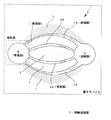
図1は、本発明に係る熱輸送装置の基本構成を示す概念図である。
【0022】
熱輸送装置1は、液相の作動流体が蒸発する蒸発部「E」(エバポレータ)と、気相の作動流体が凝縮する凝縮部「C」(コンデンサ)を備えている。尚、図には説明の便宜上、蒸発部Eと凝縮部Cをそれぞれ1つずつ示しているが、本発明の適用において、両者の数が1対1に限定される訳ではないので、ある凝縮部に対して複数の蒸発部を設けたり、ある蒸発部に対して複数の凝縮部を設けるといった、各種形態で実施できることは勿論である。
【0023】
また、熱輸送装置1は蒸発部Eと凝縮部Cとを繋ぐ流路として、液相の作動流体が流れる液相路「lq」及び気相の作動流体が流れる気相路「vp」を備えている。
【0024】
図示のように、熱輸送装置1は複数の液相路lq、lq、…を有する構成とされ、液相の作動流体はこれらを通って凝縮部Cから蒸発部Eへと移動する。尚、気相路vpの本数については、その如何を問わないので、1本でも複数本でも良く、気相の作動流体は単数又は複数の気相路を通って蒸発部Eから凝縮部Cへと移動する。
【0025】
蒸発部Eは、作動流体を還流させるために毛細管力を発生する構造(所謂ウィック)を有しており、例えば、グルーブ、メッシュ、複数のワイヤー、焼結金属等が用いられる(後述する構成形態では、基板に凹凸の溝を形成したウィック部を有している。)。
【0026】
例えば、図1に点線で示すように、電子デバイスの発熱部(電子部品や発熱体等)を蒸発部Eに対して熱的に接続し、放熱又は冷却手段を凝縮部Cに対して熱的に接続することにより、液体の作動流体が、液相路lqを通って蒸発器Eに到達し、ここで発熱部からの熱を受けて気化する。そして、気相の作動流体が、気相路vpを通って凝縮部Cに移動して、ここで熱を放出して液体に戻るというサイクルが形成されることになる。
【0027】
このような構成において、蒸発部Eのウィック部及び該ウィック部近傍の液相路の部分に気相の流体が混入した状態で加熱された場合には、気化が増長されて気相部分が成長する事になり、液相路の一部を気相が塞ぐ形となる。よって、液相の作動流体がウィック部に供給されず、予定通りに熱輸送が行われなくなってしまうといった不都合が問題となる。
【0028】
単純な解決方法として、液相路lqを凝縮部Cから蒸発部Eまで一律に細くしてしまうことが考えられるが、この方法では、確かに気相の混入に対しては効果が高まるが、液相の作動流体をウィック部の毛細管力によって還流させる熱輸送装置においては、発生する毛細管力をそれほど大きくはできないため、熱輸送距離を短くするか、最大熱輸送能力を小さくすることを余儀なくされてしまう等の問題が残る。
【0029】
そこで、本発明に係る実施形態では、高い熱輸送能力を持った熱輸送装置の提供を目的として、下記に示す事項を採用する。
【0030】
・ウィック部近傍の液相路を細くして、安定な動作を実現すること。つまり、液相路の形成方向に直交する面における断面積に関して、凝縮部側の断面積を蒸発部側の断面積よりも相対的に大きくすること。
【0031】
・液相路に関しては、流路の形成方向に直交する面における断面積を、凝縮部から蒸発部に近づくにつれて徐々に小さくすること(この点については、後で詳述する。)
・複数の液相路を設けること。
【0032】
つまり、ウィック部近傍の液相路を部分的に細くすると、液相路における液体の作動流体による圧力損失が増大するので、該圧力損失を小さくするためには、複数の液相路を設け、かつ凝縮部から蒸発部に向かって液相路の断面積を徐々に小さくしていくことが好ましい。また、液相路を複数本にすることは、ある液相路に気相の作動流体が充満して液相の流れが阻害された場合に、他の液相路を通して液相の作動流体がウィック部に供給されるので、ドライアウト防止や信頼性向上の観点からも好ましい。
【0033】
本発明では、図1に示すように、液相路lq及び気相路vpに沿って、各流路間での熱伝達を抑制するために断熱部I、I、…が設けられているので、気相路及び液相路を含む流路と、外部との熱の授受を抑制することができる。つまり、気相路及び液相路を流れる作動流体について、それぞれの流路において相変化を生じることがないので、作動流体を安定して流路に流すことができ、高い熱輸送効率を得ることができる。尚、後述するように、断熱部Iは、例えば、空洞部(キャビティ)として形成され、その場合に空洞部を密閉する形態と開放したままとする形態が挙げられる。また、図1には、液相路と気相路の間やそれらの外側に断熱部を設けているが、これに限らず、例えば、気相路及び液相路とそれぞれの断熱部とを2重管構造にし、その内管を気相路及び液相路として用い、内管と外管との間を、例えば、減圧状態にしたり、あるいは熱伝導率の小さい気体を充填することで断熱部を構成する等、各種形態での実施が可能である。
【0034】
図2乃至図9は、本発明に係る実施形態について、熱輸送装置の構成例を示したものであり、該装置は水平状態に配置されて使用される。
【0035】
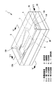
図2は分解斜視図を示しており、熱輸送装置1は、3つの基板2A、2B、2Cを用いて構成されている。即ち、第1基板2A、第2基板2B、第3基板2Cからなる3層構造を有しており、第2基板2Bが中間層を構成し、基板2A、2Cが基板2Bを両側から挟み込むようにして固定される。尚、本発明の適用においては3層構造に限らず、2層構造でも構わないが、例えば、第2基板2Bの厚みが小さい場合には、その補強のために該基板を別の基板(2A、2C)で両側から挟み込んだ構造が好ましい。
【0036】
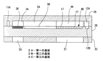
図3は熱輸送装置1を組み立てた状態を示す斜視図であり、図4は第1基板2Aに構成された流路パターンを示した平面図と、第1基板2AのA−A線での断面図と、第1基板2AのB−B線での断面図を併せて示している。そして、図5は図3に示した熱輸送装置1に係るV−V線での断面図を示し、図6は、図3に示した熱輸送装置1に係るVI−VI線での断面図を示す。
【0037】
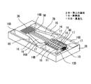
図7は第1基板2Aを示す斜視図、図8は第2基板2Bを示す斜視図、図9は第3基板2Cを示す斜視図である。
【0038】
先ず、第1基板2Aについて、図2乃至図7を参照しながら説明する。尚、本例に示す熱輸送装置1では、2本の液相路と1本の気相路を備えており、図2には第1基板2Aにおいて太線の矢印を付して作動流体の流れの向きを示している。
【0039】
図4や図7に示すように、第1基板2Aの一方の面(内面)には、蒸発部3を構成する溝(凹部)3Aと、凝縮部4を構成する溝(凹部)4Aが形成されている。
【0040】
蒸発部3と凝縮部4とを繋ぐ気相路5を構成する溝5Aについては、図示のように直線路として形成されており、また、蒸発部3と凝縮部4とを繋ぐ2本の液相路6、7は、気相路5を通って延びる中心軸に関して対称的な配置をもって形成される。つまり、液相路6を構成する溝6A及び液相路7を構成する溝7Aは、その中央に位置する気相路5の溝5Aとともにフォーク状の形状をなしており、各溝は凝縮部4の溝4Aの端部からそれぞれ熱輸送装置1の外周縁寄りの部分を通って蒸発部3の溝3Aの端部に接続されるように形成されている。例えば、図4に示すように、溝6Aは、凝縮部4の溝4Aの左上端部から連続されて曲路を描いた後、蒸発部3の溝3Aに近づくにつれて徐々に溝幅が狭まっていき、溝3Aの近傍に位置する最小幅の直線部分8Aへと繋がっている。他方、溝7Aは、凝縮部4の溝4Aの左下端部から連続されて曲路を描いた後、蒸発部3の溝3Aに近づくにつれて徐々に溝幅が狭まっていき、溝3Aの近傍に位置する最小幅の直線部分9Aへと繋がっている。このように、溝6A、7Aは、蒸発部3に近づくにつれて徐々に溝幅が狭くされた流路10A、11Aをそれぞれ有している。
【0041】
尚、気相路5及び蒸発部3、凝縮部4のそれぞれの中心部を通る軸に関して2つの液相路6、7が対称的な配置とされているので、各液相路に関する作動流体の流れが均等化され、また、抵抗や流量等の差が殆どなくなる。
【0042】
また、本例では、気相路5の溝5Aが直線状に形成され、その断面積が一定とされているが、これに限らず、気相路5の断面積を徐々に変化させた構成も可能である。
【0043】
溝12A、13Aは、作動流体を供給する供給路12、13をそれぞれ構成するものである。例えば、図4に示すように、凝縮部4の溝4Aの右側に溝12Aが形成されている。また、蒸発部3の溝3Aの左側及び上記直線部分8A、9Aの脇には、略コ字状をした溝13Aが形成されている。
【0044】
図2や図3に示すように、第1基板2Aの他方の面(外面)には供給路12A、13Aにそれぞれ連通する、作動流体の供給孔14A、15Aが基板2Aを貫通して形成されている。つまり、作動流体は、供給孔14Aから供給路12を通って凝縮部4に送れられ、また、供給孔15Aから供給路13を通って蒸発部3に送られる。尚、作動流体の供給孔14A、15Aは、作動流体を供給するとき以外は蓋等で閉じられている。
【0045】
第1基板2Aに使用する材料については、その熱伝導率があまりに高いと、基板での熱拡散によって、熱輸送装置1の熱輸送効率に悪影響を及ぼし得るので、例えば、ガラスや、ポリイミド、ポリ四ふっ化エチレン、PDMS(polydimethylsiloxane)等の合成樹脂が用いられる。また、第1基板2Aに設けられる気相路や液相路、蒸発部、凝縮部、供給路の溝は、例えば、サンドブラスト、RIE(ドライエッチング)、ウェットエッチング、UV(紫外)光エッチング、レーザエッチング、プロトン光エッチング、電子線描画エッチング又はマイクロモールディング等で形成される。
【0046】
次に、第2基板2Bについて、図2、図3、図5、図6、図8を参照しながら説明する。
【0047】
図2や図8に示すように、第2基板2Bは、作動流体を気化させる蒸発器ウィック3B、作動流体を凝縮させる凝縮器ウィック4B、液相路シール部6B、7B、気相路の溝5B、断熱部16、16、…により構成されている。
【0048】
蒸発器ウィック3Bは上記した溝3Aとともに蒸発部3を構成しており、所定方向に沿った微細な溝が形成されることで、凹凸形状を有する。
【0049】
また、凝縮器ウィック4Bは上記した溝4Aとともに凝縮部4を構成しており所定の深さをもった凹部として形成された矩形状の範囲内に、凹凸部が形成されている。つまり、本例では、多数の凸条17、17、…が形成されることで、隣接する凸条の間に溝がそれぞれ形成された構成を有する。
【0050】
溝5Bは上記した溝5Aに対応した位置に形成されており、溝5Aとともに気相路5を構成する。蒸発部3から凝縮部4への気相流体の流速が大きいことを考慮し、流路の断面積を大きくするため、気相路5については、基板2Aと2Bの両方に溝を形成している。また、溝5Bは、凝縮器ウィック4Bにおいて、凹凸が形成されていない直線路18に繋がっており、これにより凝縮部4への気相路が確保される(つまり、この直線路18が気相路として使用され、気相の作動流体が流入を妨げられずに、凝縮部4内に入ってここで熱を放散して凝縮する。)。
【0051】
液相路シール部6B、7Bは、第1基板2Aに形成された溝6A、7Aをそれぞれに塞ぐことで、作動流体の流路を形成するとともに、作動流体が流路から外部に流出するのを防いでいる。即ち、シール部6Bは、溝6Aに対応した平坦面として形成され、基板2Aと2Bとを結合した状態で液相路6を構成する。同様に、シール部7Bは、溝7Aに対応した平坦面として形成され、基板2Aと2Bとを結合した状態で液相路7を構成する。尚、液相路6、7については、第1基板2Aにだけ溝6A、7Aが形成され、第2基板2Bには溝が形成されていないが、これは気相の作動流体を液相路に入り込み難くすることを考慮したものである。
【0052】
溝12Bは供給路12を構成するものであり、第1基板2Aの溝12Aに対応した位置に形成されている。つまり、この溝12Bは、凝縮器ウィック4Bの脇に形成されており、両者の境界部分には、上記した凸条17よりも形成ピッチの狭い凹凸部分19が形成されている。尚、第2基板2Bにおいて、溝13Aに対応する場所は平坦面とされ、溝は形成されていない。つまり、供給路12についてのみ第2基板2Bには溝12Bが形成されているが、これは、非圧縮性気体が溜まり易いことを配慮したものであり、また、凹凸部分19については気体の戻り防止等を考慮している。
【0053】
図2及び図8に示すように、各断熱部16は、第2基板2Bの貫通孔16Bと、該貫通孔の開口を覆う第1基板2A及び第3基板2Cの部分によって構成される空洞部として形成されている。即ち、各空洞部は、第2基板2Bの中央部及び周辺部における貫通孔16Bの形成部分を、第1基板2A及び第3基板2Cで挟み込むことで形成されている。尚、本例では、図示のように、第2基板2Bの中央部に形成される2つの空洞部が、気相路5と液相路6、7との間にそれぞれ形成され、第2基板2Bの周辺部に形成される空洞部については、蒸発部3及び液相路6、7の両脇と、凝縮部4の両脇にそれぞれ形成されている。
【0054】
各断熱部16の内部は、減圧状態であることが好ましいが、熱伝導率の小さい気体、例えば、空気、窒素、アルゴン等が充填された状態でもよい。この断熱部16は熱伝導を抑制すること、特に第3基板2C側と、気相路5及び液相路6、7の側との間の熱移動を抑制する上で効果が大きい。
【0055】
第2基板2Bには、熱伝導率の高い材料を用いることが好ましい。例えば、シリコン(Si)等が使用されるが、これに限るものではなく、例えば、Cu、Al、Ni、Au,Ag、Pt等の金属、あるいは、導電性ポリマや、セラミックスであって、かつ金属と同等の熱伝導率を有する材料等を用いることができる。
【0056】
また、蒸発器ウィック3Bや凝縮器ウィック4Bの凹凸形状の溝、断熱部16の貫通孔16B、液相路シール部6B、7B、気相路の溝5Bについては、例えば、サンドブラスト、RIE(ドライエッチング)、ウェットエッチング、UV(紫外)光エッチング、レーザエッチング、プロトン光エッチング、電子線描画エッチング又はマイクロモールディング等で形成される。
【0057】
次に、第3基板2Cについて、図2、図3、図5、図6、図9を参照しながら説明する。
【0058】
第3基板2Cには、第2基板2Bのうち、蒸発器ウィック3Bや凝縮器ウィック4Bが設けられた側とは反対側の面に対する第1連通孔20及び第2連通孔21が形成されている。
【0059】
第1連通孔20は蒸発器ウィック3Bの裏面側に対応する位置、また第2連通孔21は凝縮器ウィック4Bの裏面側に対応する位置にそれぞれ開けられている。第1連通孔20を介して蒸発器ウィック3Bの裏面に、例えば、熱源となるデバイス(CPU、グラフィックチップ、ドライバIC等の発熱体)が接続され、その熱が蒸発部3に伝達されて冷却が行われる。一方、第2連通孔21を介して凝縮器ウィック4Bの裏面に、放熱手段(例えば、外部に熱を放出するための放熱フィン等)あるいは冷却手段が取り付けられる。
【0060】
第3基板2Cについては、第1基板2Aと同様に、熱伝導率があまり高いと、基板での熱拡散によって、熱輸送装置1の熱輸送効率に悪影響を及ぼす虞があるので、例えば、ガラスや、ポリイミド、ポリ四ふっ化エチレン、PDMS(polydimethylsiloxane)等の合成樹脂が用いられる。また、第3基板2Cに設けられる第1連通孔20及び第2連通孔21は、例えば、サンドブラスト、RIE(ドライエッチング)、ウェットエッチング、UV(紫外)光エッチング、レーザエッチング、プロトン光エッチング、電子線描画エッチングまたはマイクロモールディング等で形成される。
【0061】
作動流体としては、例えば、水、エタノール、メタノール、プロパノール(異性体を含む。)、エチルエーテル、エチレングリコール、フロリナート、アンモニア等が使用される。これらの冷媒の中から、熱輸送装置1の設計を満足する沸点、抗菌性等の特性を有するものが用いられる。また、作動流体は、第1基板2Aに設けられた供給孔14A、15Aから熱輸送装置1内に減圧の雰囲気中で供給される。
【0062】
上記のように、本形態では、第1乃至第3基板からなる3層構造を有しており、液相路6、7及び気相路5が、中間層を構成する第2基板2Bと該基板に隣接して接合される第1基板2Aとの間に形成されていて、コンパクト化に好適である。さらに、断熱部16、16、…を基板に一体化して形成することができるので、熱輸送装置1の小型化及び薄型化に適している。特に、限られたスペースに複数の液相路及び気相路を設ける必要がある場合には、液相路と気相路の距離が近くなってしまうため、両者の間に断熱部を設けることが非常に有効である。
【0063】
次に、熱輸送装置1の動作について説明する。
【0064】
液相路6、7を通って蒸発部3に向かって流れる液相の作動流体は、液相路の直線部分8A、9Aの各々から蒸発器ウィック3Bの微細な溝による毛細管力で浸透し、この毛細管力で蒸発器ウィック3B全体に広がっていく。この液相の作動流体は、蒸発器ウィック3Bが設けられている他方の面に取り付けられた図示しない熱源からの熱によって気化される。つまり、電子デバイス等の発熱部からの熱は第3基板2Cの第1連通孔20を介して熱伝導により蒸発器ウィック3B側に向けて移動し、熱伝達によって蒸発器ウィック3Bの表面から作動流体に伝えられる。
【0065】
気化した作動流体は、気相路5を通って凝縮器4に流入する。凝縮器ウィック4Bでは、気相の作動流体が潜熱を放出し、作動流体が相変化し再び液相に戻る。作動流体から奪われた熱は、第3基板2Cの第2連通孔21を介して放熱フィン等の放熱手段に熱伝達されて、外部に放出される。液化した作動流体は、蒸発器ウィック3Bの毛細管力によって、凝縮器ウィック4Bの微細な溝を流れ、さらに、凝縮部4から液相路6、7をそれぞれ通って蒸発部3の蒸発器ウィック3Bに向かって流れる。これらの一連の熱輸送が、熱輸送装置1内で繰り返し行われる。
【0066】
この一連の熱輸送過程において、図5に示すように、気相路5及び液相路6、7を構成する第2基板2Bの部分には、断熱部16、16、…が形成されていて、各断熱部は、第2基板2Bの貫通孔16Bと第1及び第3基板とで形成される空洞部として構成されている。これにより、熱源や放熱手段等が取り付けられている第3基板2Cからの熱的な影響を、気相路や液相路が受け難いという利点が得られる。また、第1基板2Aが熱伝達率の小さい材料で構成されていること、そして、第1基板2Aが第3基板2Cに比べて熱的な影響を周囲から受け難いことから、第1基板2A側の部分と作動流体との間の熱伝達の度合いは小さい。そのため、気相路5及び液相路6、7と熱輸送装置1の外部との間での、熱の授受が抑制され、気相路5及び液相路6、7を流れる作動流体がそれぞれの流路において相変化を生じないので、作動流体を安定して流すことができ、高い熱輸送効率を得ることができる。また、空洞部内を減圧状態にすることで、空洞部を介しての熱の授受をさらに抑制することができ、さらには、空洞部内に基板材料よりも熱伝導率の小さな気体を充填することによってその効果を高めることが可能である。
【0067】
上記した熱輸送装置1の製造方法について、図2、図3、図7乃至図9を参照して説明する。
【0068】
図7に示すように、第1基板2Aの片面に、気相路5の溝5A、気相路5と連通する蒸発部3の溝3A、凝縮部4の溝4A、作動流体の供給路12、13の各溝12A、13Aを、例えば、サンドブラストによって形成する。また、第1基板2Aの外面には、供給路12、13にそれぞれ連通する供給孔14A、15Aを開ける。
【0069】
続いて、図8に示すように、第2基板2Bにおいて、蒸発器ウィック3B、凝縮器ウィック4B、気相路の溝5B、断熱部16、16、…の貫通孔16B、16B、…を、例えば、サンドブラストによって形成する。尚、蒸発器ウィック3B及び凝縮器ウィック4Bには、凹凸形状の溝を形成する。
【0070】
次に、図9に示すように、例えば、サンドブラストによって、第3基板2Cに、第1連通孔20及び第2連通孔21を形成する。尚、第1連通孔20は第2基板2Bの蒸発器ウィック3Bの裏面に対応した位置に開け、また、第2連通孔21は第2基板2Bの凝縮器ウィック4Bの裏面に対応する位置に開ける。
【0071】
それから、図2、図3に示すように、第1基板2Aのうち、流路(気相路及び液相路)が形成されている溝側の面と、第2基板2Bにおいて蒸発部や凝縮部の各ウィックが形成されている方の面とを向かい合わせ、蒸発部3の溝3Aと蒸発器ウィック3B、及び凝縮部4の溝4Aと凝縮器ウィック4Bとを互いに位置合わせしてから、第1基板2Aと第2基板2Bとを接合する。
【0072】
第3基板2Cについては、第2基板2Bのうち上記の各ウィックが形成されている側と反対の面において、第1連通孔20を蒸発器ウィック3Bの裏面側に位置合わせし、第2連通孔21を凝縮器ウィック4Bの裏面側に位置合わせした状態で、第2基板2Bに接合する(図2、図3参照。)。そして、第1連通孔20を通して第2基板2Bには、発熱するデバイス等からの熱が伝達されるとともに、第2連通孔21を通して第2基板2Bの凝縮部4の熱が放熱手段等に伝達されて放散されるように配置及び設定を行えば良い。
【0073】
尚、第1基板2A、第2基板2B、第3基板2Cの接合にあたって、例えば、第2基板2Bにガラス基板を用いる場合は、該基板の両接合面に水素化アモルファスシリコン(a‐Si:H)膜を成膜し、陽極接合を用いることで、第1基板2A及び第3基板2Cとの接合を行う。また、接合方法については、陽極接合に限られないので、例えば、接着剤として樹脂を用いた接着接合や、熱圧着等の圧着接合又はレーザ溶接等の溶接接合といった各種形態の採用が可能である。
【0074】
また、3基板2A、2B、2Cの接合は、減圧の雰囲気中で行い、これらの接合によって形成される断熱部16の内部が減圧状態になる。尚、3基板の接合については減圧の雰囲気中に限らず、例えば、空気、窒素、アルゴン等の熱伝導率の小さい気体の雰囲気中で行っても良い。
【0075】
第1基板2Aに設けられた作動流体の供給孔14A、15Aから熱輸送装置1内に作動流体が減圧の雰囲気中で供給され、これらの供給孔を閉じて熱輸送装置1の製作が完了する。
【0076】
上記した熱輸送装置1の製造方法について、その工程を箇条書きにしてまとめると、下記のようになる。
【0077】
(1)基板に、液相の作動流体が流れる液相路及び気相の作動流体が流れる気相路、液相の作動流体を還流させるために毛細管力を発生するウィック部を形成する流路形成工程
(2)基板に、液相路及び気相路に沿って断熱部を形成する断熱部形成工程
(3)断熱部を減圧の雰囲気中において密閉する密閉工程。
【0078】
尚、(1)と(2)の工程については、1つの工程として行っても良い。また、(3)の断熱部の密閉工程は、基板の形成材料よりも熱伝導率の小さな気体の雰囲気中で行っても良い。
【0079】
この製造方法によれば、基板の気相路及び液相路に沿って断熱部が形成されることで、気相路及び液相路と熱輸送装置の外部との間で熱の授受が抑制され、作動流体を安定して流すことができる。
【0080】
そして、熱輸送装置1によれば、例えば、下記に示す利点が得られる。
【0081】
・気相路5及び液相路6、7の第2基板2B側の部分には、断熱部16が形成されているので、熱源に近い第3基板2Cからの熱的影響を受け難いこと。
【0082】
・第1基板2Aが熱伝達率の小さい材料で構成されており、しかも第1基板2Aが第3基板2Cに比べて熱的な影響を周囲から受けにくい状態にあることから、第1基板2A側部分と作動流体との間の熱伝達を小さくすることができ、その結果、気相路5内で作動流体が液化したり、液相路6、7内で作動流体が気化するといった相変化が生じないこと。
【0083】
・断熱部16を基板に一体化して形成することができるので、熱輸送装置1の小型化及び薄型化に適していること。
【0084】
尚、上記した構成では、基板2A、2B、2Cを接合させた3層構造を有し、液相路及び気相路が、中間層をなす第2基板2Bと第1基板2Aとの間に形成されているが、このような実施形態のみには限らない。例えば、2枚の基板を接合したものと蒸発部及び凝縮部を備えた構造でも良い。一例としては、基部を構成する第1基板と第2基板において、互いの接合面に、気相路や液相路、断熱部の溝を形成する。そして、一方の基板には、気相路や液相路のそれぞれと連通する蒸発部、凝縮部のための孔を形成し、これらの孔から、蒸発器ウィックや凝縮器ウィックの凹凸形状の溝を各別に挿入して基板と接合する。蒸発器ウィックにおいて、凹凸形状の溝が形成されていない方の面に、発熱するデバイス等が接続され、また、凝縮器ウィックのうち凹凸形状の溝が形成されていない方の面に、放熱フィン等を設ければ良い。
【0085】
要は、基板に形成された気相路や液相路の周囲に、減圧状態又は熱伝導率の小さい気体が充填された状態の断熱部を有する構成ならば如何なる構成でも良く、また、上記した構成、材料等については必要に応じて変更することができる。
【0086】
【発明の効果】
以上に記載したところから明らかなように、請求項1や請求項20に係る発明によれば、複数の液相路を形成することにより、液相路への気相混入に起因する装置の性能低下や機能不全を防止することができるので、熱輸送能力及び熱輸送効率に優れた熱輸送装置を実現できる。
【0087】
請求項2、5、6、12、15、16に係る発明によれば、熱輸送装置の小型化や薄型化に好適である。
【0088】
請求項3、4、13、14に係る発明によれば、液相路及び気相路内での作動流体の相変化を防止することができる。
【0089】
請求項7、8、17、18に係る発明によれば、断熱部を空洞部として形成し、また、これを減圧状態とすることにより、構成の複雑化やコスト上昇を伴わずに、液相路、気相路への熱的影響を低減することができる。
【0090】
請求項9、19に係る発明によれば、熱伝導率の小さな気体を用いることで充分な断熱効果を得ることができる。
【0091】
請求項10に係る発明によれば、液相路の断面積を一律に小さくするのではなく、凝縮部側断面積と蒸発部側断面積との相対的な大小関係において、凝縮部側断面積をより大きくすることによって、熱輸送距離及び最大熱輸送能力を充分に得ることができる。
【0092】
請求項11、21に係る発明によれば、液相路の断面積を、凝縮部から蒸発部に向かって徐々に小さくすることにより、液相路部分の毛細管力を大きくすることができ、当該部分への気相の混入を防ぐことで安定した動作を実現できる。
【図面の簡単な説明】
【図1】本発明に係る基本構成を示す概念図である。
【図2】本発明に係る実施形態に示す熱輸送装置の分解斜視図である。
【図3】図2の熱輸送装置を組み立てた状態を示す斜視図である。
【図4】第1基板に構成された流路や蒸発部、凝縮部等について説明するための図であり、上段に平面図を示し、中段にA−A線における断面図、下段にB−B線における断面図を示す。
【図5】図3のV−V線に沿う拡大断面図である。
【図6】図3のVI−VI線に沿う拡大断面図である。
【図7】図8及び図9とともに、各基板に係る形成工程について説明するための図であり、本図は、第1基板上の流路等を示す斜視図である。
【図8】第2基板上のウィックや断熱部等を示す斜視図である。
【図9】第3基板上の連通孔を示す斜視図である。
【符号の説明】
1…熱輸送装置、2A、2B、2C…基板、2A…第一の基板、2B…第二の基板、2C…第三の基板、3…蒸発部、4…凝縮部、5…気相路、6、7…液相路、16…断熱部、16B…貫通孔[0001]
TECHNICAL FIELD OF THE INVENTION
The present invention relates to a heat transport device including an evaporator and a condenser, and an electronic device. More specifically, the present invention relates to a technique for performing heat transport suitable for miniaturization and thinning using a capillary pumped loop (CPL), a loop heat pipe, or the like in the field of fluid MEMS (Micro-Electro-Mechanical Systems).
[0002]
[Prior art]
Various devices (heat pipes, heat sinks, radiating fins, etc.) are widely used for heat dissipation and cooling, but with the recent development of electronic device technology and micromachine technology, it has become possible to create compact devices. A so-called MEMS technology utilizing a semiconductor manufacturing process or the like has attracted attention. Researches have been made to use this MEMS technology for heat transport devices. Behind this is the need for a heat source cooling system suitable for small, high-performance electronic equipment, and the efficiency of heat generated by devices such as CPUs (Central Processing Units), whose processing speed and other performance are significantly improved. It is necessary to dissipate heat well.
[0003]
In a configuration using a capillary pump loop, for example, a cycle in which heat of an object is removed by vaporizing a refrigerant in an evaporating section and the vaporized refrigerant is returned to a liquid in a condensing section is repeated (for example, Non-Patent Document 1). reference).
[0004]
In a system configuration including an evaporator and a condenser, heat transport is basically performed by the following method.
[0005]
(1) The liquid working fluid transported from the condensing section reaches the evaporating section through the liquid phase path, and is vaporized by receiving external heat in the evaporating section.
(2) The vaporized working fluid moves at high speed through the gas phase path toward the condensing section, releases heat to the outside in the condensing section, and returns to liquid again.
(3) A series of heat transports of (1) and (2) are repeatedly performed in a closed pipe.
[0006]
[Non-patent document 1]
Jeffrey Kirshberg, Dorian Liepmann, Kirk L. Yerkes, "Micro-Cooler for Chip-Level Temperature Control", Aerospace Power Systems Conference Proceedings, (USA), Society of Automotive Engineers, Inc., April 1999, P-341, p.233-238
[0007]
[Problems to be solved by the invention]
However, the conventional apparatus has the following problems regarding heat transport efficiency and heat transport capacity.
[0008]
In a heat transport system with an evaporator and a condenser, if the gas in the gas phase releases heat and condenses back to a liquid before reaching the condenser, the liquid moves the gas. , The heat transport efficiency may be reduced.
[0009]
Further, if the liquid in the liquid phase path is vaporized by receiving heat from the outside before reaching the evaporating section, the movement of the liquid is hindered by the gas, so that the heat transport efficiency may be reduced.
[0010]
Furthermore, in the initial state at the start of operation, the liquid phase passage and the wick portion (having the role of holding and refluxing the working fluid) need to be filled with the working fluid in the liquid phase. Therefore, in order to perform stable heat transport, it is necessary to fill the wick portion and the liquid phase passage with the liquid-phase working fluid at the start of the operation, and to reduce the cross-sectional area of the liquid phase passage, and to cause the liquid to flow by the capillary force. It is necessary to increase holding power.
[0011]
In this case, if the fluid resistance in the liquid phase path increases, the distance over which heat can be transported becomes shorter, and the amount of heat may be reduced. That is, in the heat transport device that recirculates the working fluid by the limited capillary force of the wick portion, there is a problem that the heat transport capability (heat transport distance and heat transport amount) is reduced. In particular, when restarting after a dry-out (phenomenon in which the evaporating part dries) due to excessive thermal input, the working fluid is not supplied to the wick part, and as a result, the wick part does not function as a heat transport device. Can also occur.
[0012]
A solution to the problem caused by the phase change of the working fluid due to the transfer of heat to and from the outside in the gas phase path and the liquid phase path (the flow of the working fluid is hindered and the heat transport efficiency is reduced). As a large device system, a method is known in which the periphery of a gas phase path and a liquid phase path is covered with a heat insulating material to suppress the transfer of heat with the outside. However, this method has a problem that the structure of the heat transport device is complicated, and cannot be applied to a small heat transport device in which a flow path of a working fluid is formed in a substrate. Therefore, in a device that attaches importance to a small and thin structure, an effective means for suppressing the transfer of heat with the outside is hardly taken, which causes a reduction in heat transport efficiency.
[0013]
Therefore, an object of the present invention is to provide a heat transport device having high heat transport capability and heat transport efficiency and suitable for miniaturization and thinning.
[0014]
[Means for Solving the Problems]
The first heat transport device and the electronic device according to the present invention have a plurality of liquid phase paths as a flow path connecting the evaporating section and the condensing section, and the evaporating section generates a capillary force to recirculate a working fluid. It has a structure.
[0015]
Therefore, according to the present invention, by forming a plurality of liquid phase paths, it is possible to prevent performance degradation and malfunction of the apparatus due to mixing of the gas phase into the liquid phase paths. For example, even if a gas phase is mixed into one liquid phase path and the reflux of the liquid phase working fluid is hindered, the liquid phase working fluid flows through the remaining sound liquid path through the wick section. , It is possible to prevent dryout and the like.
[0016]
Further, the second heat transport device or the electronic device according to the present invention has a configuration in which a cross-sectional area of a liquid phase path in a plane orthogonal to a forming direction is gradually reduced from a condensation section toward an evaporation section. Have
[0017]
Therefore, according to the present invention, it is possible to increase the capillary force in the liquid phase passage portion, and to prevent the gas phase from being mixed into the portion. As a result, even after a dryout due to an excessive input, the wick portion and the liquid path portion in the vicinity thereof are filled with the liquid-phase working fluid, so that a stable operation can be realized.
[0018]
In the configuration having both the first and second aspects of the invention, that is, in the form of forming a plurality of liquid phase paths and gradually reducing the cross-sectional area from the condensing section to the evaporating section, the liquid phase path section It is possible to reduce the pressure loss caused by the flow of the working fluid in the liquid phase in the above.
[0019]
BEST MODE FOR CARRYING OUT THE INVENTION
The heat transport device according to the present invention is suitable for a device using a capillary pump loop, a loop heat pipe, or the like, and can be applied to a heat radiation or cooling system of various electronic devices. For example, in application to information processing apparatuses such as computers, portable devices, and the like, various devices serving as heat sources (for example, CPUs, imaging devices, light emitting devices, small hard disk drives, optical media drives, and the like are used). The heat dissipation structure and the cooling structure of the drive motor or the actuator which is subjected to severe thermal conditions) are effective when it is desired to realize the efficiency without violating the demand for the reduction in size and thickness of the device.
[0020]
Here, the term "heat transport device" means, in a narrow sense, a device for transferring heat from a heating element by a working fluid or the like, but in a broad sense, a heating element, a cooling means or a heat radiating means, and a temperature control. It means the entire equipment system including the equipment.
[0021]
FIG. 1 is a conceptual diagram showing a basic configuration of a heat transport device according to the present invention.
[0022]
The heat transport device 1 includes an evaporator “E” (evaporator) for evaporating a liquid-phase working fluid and a condenser “C” (condenser) for condensing a gas-phase working fluid. Although only one evaporating section E and one condensing section C are shown in the figure for convenience of explanation, the number of both is not limited to one to one in the application of the present invention. Of course, the present invention can be implemented in various forms, such as providing a plurality of evaporating sections for each section, and providing a plurality of condensing sections for a certain evaporating section.
[0023]
Further, the heat transport device 1 includes a liquid phase path “lq” through which a liquid-phase working fluid flows and a gas-phase path “vp” through which a gas-phase working fluid flows as a flow path connecting the evaporating section E and the condensing section C. ing.
[0024]
As shown in the figure, the heat transport device 1 is configured to have a plurality of liquid phase paths lq, lq,..., And the working fluid in the liquid phase moves from the condensing section C to the evaporating section E through these. It should be noted that the number of the gas phase passages vp is not limited, and may be one or more. The working fluid in the gas phase passes from the vaporization section E to the condensation section C through one or more gas phase paths. And move.
[0025]
The evaporator E has a structure (so-called wick) that generates a capillary force to recirculate the working fluid, and for example, a groove, a mesh, a plurality of wires, a sintered metal, or the like is used (a configuration described later). Has a wick portion in which an uneven groove is formed in the substrate.)
[0026]
For example, as shown by a dotted line in FIG. 1, a heat-generating portion (electronic component, heat-generating body, etc.) of the electronic device is thermally connected to the evaporating portion E, and a heat radiating or cooling means is thermally connected to the condensing portion C. , The liquid working fluid reaches the evaporator E through the liquid phase passage lq, where it receives heat from the heat generating portion and is vaporized. Then, a cycle is formed in which the gas-phase working fluid moves to the condensing section C through the gas-phase path vp, where heat is released and returned to liquid.
[0027]
In such a configuration, when the wick portion of the evaporating portion E and the portion of the liquid phase path near the wick portion are heated with the gas phase fluid mixed therein, the vaporization is increased and the gas phase portion grows. Therefore, a part of the liquid phase path is closed by the gas phase. Therefore, there is a problem that the liquid-phase working fluid is not supplied to the wick portion, and heat transfer is not performed as scheduled.
[0028]
As a simple solution, it is conceivable that the liquid phase path lq is uniformly narrowed from the condensing section C to the evaporating section E. However, this method certainly increases the effect on mixing of the gas phase, In a heat transport device that recirculates a liquid-phase working fluid by the capillary force of the wick, the generated capillary force cannot be so large, so it is necessary to shorten the heat transport distance or reduce the maximum heat transport capability. Problems remain.
[0029]
Therefore, in the embodiment according to the present invention, the following items are adopted for the purpose of providing a heat transport device having high heat transport capability.
[0030]
・ To achieve stable operation by narrowing the liquid phase path near the wick. That is, regarding the cross-sectional area in a plane orthogonal to the direction in which the liquid phase path is formed, the cross-sectional area on the condensing section side should be relatively larger than the cross-sectional area on the evaporating section side.
[0031]
Regarding the liquid phase path, the cross-sectional area in a plane orthogonal to the direction in which the flow path is formed is gradually reduced from the condensing section to the evaporating section (this point will be described in detail later).
・ Provide multiple liquid phase paths.
[0032]
That is, when the liquid phase path near the wick portion is partially narrowed, the pressure loss due to the working fluid of the liquid in the liquid phase path increases, so that in order to reduce the pressure loss, a plurality of liquid phase paths are provided. Further, it is preferable to gradually reduce the cross-sectional area of the liquid phase passage from the condensing section to the evaporating section. In addition, by using a plurality of liquid phase paths, when a certain liquid phase path is filled with a gas phase working fluid and the flow of the liquid phase is obstructed, the working fluid of the liquid phase passes through another liquid phase path. Since it is supplied to the wick portion, it is preferable from the viewpoint of preventing dryout and improving reliability.
[0033]
In the present invention, as shown in FIG. 1, the heat insulating portions I, I,... Are provided along the liquid phase path lq and the gas phase path vp in order to suppress heat transfer between the flow paths. The transfer of heat between the flow path including the gas phase path and the liquid phase path and the outside can be suppressed. That is, the working fluid flowing through the gas phase path and the liquid phase path does not undergo a phase change in each of the flow paths, so that the working fluid can be stably flowed through the flow paths, and high heat transport efficiency can be obtained. Can be. In addition, as described later, the heat insulating portion I is formed as, for example, a hollow portion (cavity), and in this case, there are a mode in which the hollow section is sealed and a mode in which the hollow section is kept open. Further, in FIG. 1, a heat insulating portion is provided between and outside of the liquid phase path and the gas phase path, but the present invention is not limited to this. A double pipe structure, the inner pipe of which is used as a gas phase path and a liquid phase path, and the space between the inner pipe and the outer pipe is insulated by, for example, reducing the pressure or filling a gas having a low thermal conductivity. The present invention can be implemented in various forms, such as configuring a unit.
[0034]
2 to 9 show a configuration example of a heat transport device according to the embodiment of the present invention, and the device is used while being arranged in a horizontal state.
[0035]
FIG. 2 is an exploded perspective view, and the heat transport device 1 is configured using three
[0036]
FIG. 3 is a perspective view showing a state in which the heat transport device 1 is assembled. FIG. 4 is a plan view showing a flow path pattern formed on the
[0037]
FIG. 7 is a perspective view showing the
[0038]
First, the
[0039]
As shown in FIGS. 4 and 7, on one surface (inner surface) of the
[0040]
The
[0041]
In addition, since the two
[0042]
Further, in this example, the
[0043]
The
[0044]
As shown in FIGS. 2 and 3, working
[0045]
Regarding the material used for the
[0046]
Next, the
[0047]
As shown in FIGS. 2 and 8, the
[0048]
The
[0049]
The
[0050]
The
[0051]
The liquid
[0052]
The groove 12B constitutes the
[0053]
As shown in FIGS. 2 and 8, each of the
[0054]
The inside of each
[0055]
It is preferable to use a material having high thermal conductivity for the
[0056]
For example, sand blasting, RIE (drying) is used for the uneven grooves of the
[0057]
Next, the third substrate 2C will be described with reference to FIGS. 2, 3, 5, 6, and 9. FIG.
[0058]
In the third substrate 2C, a
[0059]
The
[0060]
Regarding the third substrate 2C, as in the case of the
[0061]
As the working fluid, for example, water, ethanol, methanol, propanol (including isomers), ethyl ether, ethylene glycol, florinate, ammonia and the like are used. Among these refrigerants, those having characteristics such as a boiling point and antibacterial properties that satisfy the design of the heat transport device 1 are used. The working fluid is supplied into the heat transport device 1 from the
[0062]
As described above, in the present embodiment, the liquid crystal display device has a three-layer structure including the first to third substrates, and the
[0063]
Next, the operation of the heat transport device 1 will be described.
[0064]
The working fluid in the liquid phase flowing toward the evaporating
[0065]
The vaporized working fluid flows into the condenser 4 through the
[0066]
In this series of heat transport processes, as shown in FIG. 5, heat insulating
[0067]
A method for manufacturing the above-described heat transport device 1 will be described with reference to FIGS. 2, 3, 7 to 9.
[0068]
As shown in FIG. 7, a
[0069]
Subsequently, as shown in FIG. 8, in the
[0070]
Next, as shown in FIG. 9, the
[0071]
Then, as shown in FIG. 2 and FIG. 3, the surface of the
[0072]
Regarding the third substrate 2C, the
[0073]
In joining the
[0074]
The bonding of the three
[0075]
The working fluid is supplied into the heat transport device 1 from the working
[0076]
The steps of the method of manufacturing the heat transport device 1 described above are summarized as follows.
[0077]
(1) A flow path that forms a liquid phase path through which a liquid-phase working fluid flows, a gas phase path through which a gas-phase working fluid flows, and a wick portion that generates a capillary force to recirculate the liquid-phase working fluid in the substrate. Forming process
(2) A heat insulating portion forming step of forming a heat insulating portion on a substrate along a liquid phase path and a gas phase path.
(3) A sealing step of sealing the heat insulating part in a reduced pressure atmosphere.
[0078]
The steps (1) and (2) may be performed as one step. The step (3) of sealing the heat insulating portion may be performed in a gas atmosphere having a lower thermal conductivity than the material of the substrate.
[0079]
According to this manufacturing method, heat transfer between the gas phase path and the liquid phase path and the outside of the heat transport device is suppressed by forming the heat insulating portion along the gas phase path and the liquid phase path of the substrate. As a result, the working fluid can flow stably.
[0080]
According to the heat transport device 1, for example, the following advantages can be obtained.
[0081]
Since the
[0082]
The
[0083]
The heat-insulating
[0084]
In the above-described configuration, the three-layer structure in which the
[0085]
In short, any configuration may be used as long as the configuration has a heat insulating portion in a reduced pressure state or a state filled with a gas having a small thermal conductivity around the gas phase path and the liquid phase path formed on the substrate, and The configuration, material, and the like can be changed as needed.
[0086]
【The invention's effect】
As is apparent from the above description, according to the first and twentieth aspects of the present invention, by forming a plurality of liquid phase paths, the performance of the apparatus caused by gas phase mixing into the liquid phase paths Since a decrease or malfunction can be prevented, a heat transport device excellent in heat transport capacity and heat transport efficiency can be realized.
[0087]
According to the second, fifth, sixth, twelfth, fifteenth and sixteenth aspects, the heat transport device is suitable for miniaturization and thinning.
[0088]
According to the third, fourth, thirteenth, and fourteenth aspects, it is possible to prevent a phase change of the working fluid in the liquid phase path and the gas phase path.
[0089]
According to the seventh, eighth, seventeenth and eighteenth aspects of the present invention, the heat insulating portion is formed as a hollow portion, and is formed in a decompressed state. Path, and the thermal influence on the gas phase path can be reduced.
[0090]
According to the ninth and nineteenth aspects, it is possible to obtain a sufficient heat insulating effect by using a gas having a small thermal conductivity.
[0091]
According to the tenth aspect of the present invention, the cross-sectional area of the liquid phase path is not uniformly reduced, but the cross-sectional area of the condensing section is relatively small in relation to the cross-sectional area of the condensing section and the cross-sectional area of the evaporating section. By further increasing the value, the heat transfer distance and the maximum heat transfer capacity can be sufficiently obtained.
[0092]
According to the invention according to
[Brief description of the drawings]
FIG. 1 is a conceptual diagram showing a basic configuration according to the present invention.
FIG. 2 is an exploded perspective view of the heat transport device shown in the embodiment according to the present invention.
FIG. 3 is a perspective view showing a state where the heat transport device of FIG. 2 is assembled.
FIG. 4 is a view for explaining a flow path, an evaporating section, a condensing section, and the like formed on the first substrate, wherein a top view is a plan view, a middle section is a sectional view taken along line AA, and a lower section is B- FIG. 4 shows a cross-sectional view taken along line B.
FIG. 5 is an enlarged sectional view taken along line VV in FIG. 3;
FIG. 6 is an enlarged sectional view taken along the line VI-VI of FIG. 3;
FIG. 7 is a diagram for explaining a forming process for each substrate together with FIG. 8 and FIG. 9, and FIG. 7 is a perspective view showing a flow path and the like on a first substrate.
FIG. 8 is a perspective view showing a wick, a heat insulating portion, and the like on a second substrate.
FIG. 9 is a perspective view showing a communication hole on a third substrate.
[Explanation of symbols]
DESCRIPTION OF SYMBOLS 1 ... Heat transport apparatus, 2A, 2B, 2C ... Substrate, 2A ... 1st substrate, 2B ... 2nd substrate, 2C ... 3rd substrate, 3 ... Evaporation part, 4 ... Condensing part, 5 ... Gas phase path , 6, 7: liquid phase path, 16: heat insulating part, 16B: through hole
Claims (21)
前記蒸発部と前記凝縮部とを繋ぐ流路として複数の液相路を有するとともに、前記蒸発部が作動流体を還流させるために毛細管力を発生する構造を有している
ことを特徴とする熱輸送装置。Heat transport including an evaporator for evaporating a liquid-phase working fluid, a condensing part for condensing a gas-phase working fluid, and a liquid-phase passage through which a liquid-phase working fluid flows and a gas-phase passage through which a gas-phase working fluid flows. In the device,
Heat having a plurality of liquid phase paths as a flow path connecting the evaporating section and the condensing section, and having a structure in which the evaporating section generates a capillary force to recirculate a working fluid. Transport equipment.
ことを特徴とする請求項1記載の熱輸送装置。The heat transport device according to claim 1, wherein the plurality of liquid paths, one or more gas paths, and the condensing unit and the evaporating unit are formed using the same substrate.
ことを特徴とする請求項1記載の熱輸送装置。The heat transport device according to claim 1, wherein a heat insulating portion is provided along the liquid phase path and the gas phase path to suppress heat transfer outside or between the flow paths.
ことを特徴とする請求項2記載の熱輸送装置。The heat transport device according to claim 2, wherein a heat insulating portion is provided along the liquid phase path and the gas phase path to suppress heat transfer between the outside and each flow path.
ことを特徴とする請求項2記載の熱輸送装置。The substrate has a three-layer structure composed of first to third substrates, and the liquid phase path and the gas phase path include a second substrate constituting an intermediate layer and a first substrate adjacent to the substrate. The heat transport device according to claim 2, wherein the heat transport device is formed between the substrate and the substrate.
ことを特徴とする請求項4記載の熱輸送装置。The substrate has a three-layer structure composed of first to third substrates, and the liquid phase path and the gas phase path include a second substrate constituting an intermediate layer and a first substrate adjacent to the substrate. The heat transport device according to claim 4, wherein the heat transport device is formed between the substrate and the substrate.
ことを特徴とする請求項4記載の熱輸送装置。5. The heat insulating part is formed as a cavity formed by a through hole formed in a second substrate and first and third substrates covering an opening of the through hole. A heat transport device as described.
ことを特徴とする請求項7記載の熱輸送装置。The heat transport device according to claim 7, wherein the inside of the cavity is in a reduced pressure state.
ことを特徴とする請求項7記載の熱輸送装置。The heat transport device according to claim 7, wherein the cavity is filled with a gas having a smaller thermal conductivity than a material used for the first to third substrates.
ことを特徴とする請求項1記載の熱輸送装置。2. The heat transport device according to claim 1, wherein, with respect to the liquid phase path, a cross-sectional area on the condensing section side is larger than a cross-sectional area on the evaporating section side. 3.
前記液相路に関して、流路の形成方向に直交する面における断面積が、前記凝縮部から前記蒸発部に向かって徐々に小さくされている
ことを特徴とする熱輸送装置。It has a structure that generates capillary force to recirculate the working fluid, and has an evaporating section in which the working fluid in the liquid phase evaporates, a condensing section in which the working fluid in the gas phase condenses, and a liquid phase in which the working fluid in the liquid phase flows In a heat transport device provided with a gas flow path through which a working fluid in a gas flow path flows,
The heat transport device according to claim 1, wherein a cross-sectional area of the liquid phase path in a plane perpendicular to a direction in which the flow path is formed is gradually reduced from the condensing section toward the evaporating section.
ことを特徴とする請求項11記載の熱輸送装置。The heat transport device according to claim 11, wherein the liquid phase path and the gas phase path, and the condensing part and the evaporating part are formed using the same substrate.
ことを特徴とする請求項11記載の熱輸送装置。The heat transport device according to claim 11, wherein a heat insulating portion is provided along the liquid phase path and the gas phase path to suppress heat transfer to the outside or between the flow paths.
ことを特徴とする請求項12記載の熱輸送装置。13. The heat transport device according to claim 12, wherein a heat insulating portion is provided along the liquid phase path and the gas phase path to suppress heat transfer outside or between the flow paths.
ことを特徴とする請求項12記載の熱輸送装置。The substrate has a three-layer structure composed of first to third substrates, and the liquid phase path and the gas phase path include a second substrate constituting an intermediate layer and a first substrate adjacent to the substrate. The heat transport device according to claim 12, wherein the heat transport device is formed between the substrate and the substrate.
ことを特徴とする請求項14記載の熱輸送装置。The substrate has a three-layer structure composed of first to third substrates, and the liquid phase path and the gas phase path include a second substrate constituting an intermediate layer and a first substrate adjacent to the substrate. The heat transport device according to claim 14, wherein the heat transport device is formed between the substrate and the substrate.
ことを特徴とする請求項16記載の熱輸送装置。The said heat insulation part is formed as a hollow part comprised by the through-hole provided in the said 2nd board | substrate, and the 1st and 3rd board | substrates which cover the opening of this through-hole. A heat transport device according to claim 16,
ことを特徴とする請求項17記載の熱輸送装置。18. The heat transport device according to claim 17, wherein the inside of the cavity is in a reduced pressure state.
ことを特徴とする請求項17記載の熱輸送装置。The heat transport device according to claim 17, wherein the cavity is filled with a gas having a smaller thermal conductivity than a material used for the first to third substrates.
前記蒸発部と前記凝縮部とを繋ぐ流路として複数の液相路を有するとともに、前記蒸発部が作動流体を還流させるために毛細管力を発生する構造を有している
ことを特徴とする電子デバイス。An evaporator is connected to the heat-generating unit thermally, and evaporates the liquid-phase working fluid; a condenser, which condenses the gas-phase working fluid; a liquid-phase passage through which the liquid-phase working fluid flows, and a gas-phase working fluid. In an electronic device having a heat transport mechanism including a flowing gas path,
An electronic device comprising: a plurality of liquid phase paths as a flow path connecting the evaporating section and the condensing section; and a structure in which the evaporating section generates a capillary force to recirculate a working fluid. device.
前記液相路に関して、流路の形成方向に直交する面における断面積が、前記凝縮部から前記蒸発部に向かって徐々に小さくされている
ことを特徴とする電子デバイス。An evaporating section having a structure for generating capillary force to recirculate the working fluid and having a heating section thermally connected to evaporate a liquid-phase working fluid, a condensing section for condensing a gas-phase working fluid, In an electronic device having a heat transport mechanism including a liquid phase path through which a liquid-phase working fluid flows and a gas phase path through which a gas-phase working fluid flows,
The electronic device according to claim 1, wherein a cross-sectional area of the liquid phase path in a plane perpendicular to a direction in which the flow path is formed is gradually reduced from the condensing section toward the evaporating section.
Priority Applications (6)
| Application Number | Priority Date | Filing Date | Title |
|---|---|---|---|
| JP2002361019A JP2004190976A (en) | 2002-12-12 | 2002-12-12 | Heat transport device and electronic device |
| US10/724,838 US6942021B2 (en) | 2002-12-12 | 2003-12-02 | Heat transport device and electronic device |
| KR1020030088999A KR20040051517A (en) | 2002-12-12 | 2003-12-09 | Heat Transfer Device and Electro Device |
| CNB2003101205301A CN1296671C (en) | 2002-12-12 | 2003-12-12 | Heat-transfer apparatus and electronic apparatus |
| US11/043,132 US7000686B2 (en) | 2002-12-12 | 2005-01-27 | Heat transport device and electronic device |
| US11/086,361 US6976526B2 (en) | 2002-12-12 | 2005-03-23 | Heat transport device and electronic device |
Applications Claiming Priority (1)
| Application Number | Priority Date | Filing Date | Title |
|---|---|---|---|
| JP2002361019A JP2004190976A (en) | 2002-12-12 | 2002-12-12 | Heat transport device and electronic device |
Publications (1)
| Publication Number | Publication Date |
|---|---|
| JP2004190976A true JP2004190976A (en) | 2004-07-08 |
Family
ID=32759916
Family Applications (1)
| Application Number | Title | Priority Date | Filing Date |
|---|---|---|---|
| JP2002361019A Pending JP2004190976A (en) | 2002-12-12 | 2002-12-12 | Heat transport device and electronic device |
Country Status (4)
| Country | Link |
|---|---|
| US (3) | US6942021B2 (en) |
| JP (1) | JP2004190976A (en) |
| KR (1) | KR20040051517A (en) |
| CN (1) | CN1296671C (en) |
Cited By (8)
| Publication number | Priority date | Publication date | Assignee | Title |
|---|---|---|---|---|
| JP2006250455A (en) * | 2005-03-11 | 2006-09-21 | Sony Corp | Heat transport device and electronic equipment |
| JP2007010249A (en) * | 2005-06-30 | 2007-01-18 | Toshiba Corp | Cooling device, and electronic apparatus |
| US8705236B2 (en) | 2011-09-29 | 2014-04-22 | Fujitsu Limited | Loop heat pipe and electronic apparatus |
| WO2014157147A1 (en) * | 2013-03-27 | 2014-10-02 | 古河電気工業株式会社 | Cooling apparatus |
| JP2019120756A (en) * | 2017-12-28 | 2019-07-22 | セイコーエプソン株式会社 | Cooling device and projector |
| US10420253B2 (en) | 2016-05-09 | 2019-09-17 | Fujitsu Limited | Loop heat pipe, manufacturing method thereof, and electronic device |
| KR20210000498A (en) * | 2019-06-25 | 2021-01-05 | 한온시스템 주식회사 | Cooling device |
| KR20210152425A (en) * | 2018-06-29 | 2021-12-15 | 쥬니퍼 네트워크스, 인크. | Thermal management with variable conductance heat pipe |
Families Citing this family (47)
| Publication number | Priority date | Publication date | Assignee | Title |
|---|---|---|---|---|
| JP2004077051A (en) * | 2002-08-20 | 2004-03-11 | Sony Corp | Heat transport device and its manufacturing method |
| US7795723B2 (en) * | 2004-02-05 | 2010-09-14 | Analog Devices, Inc. | Capped sensor |
| US7713849B2 (en) * | 2004-08-20 | 2010-05-11 | Illuminex Corporation | Metallic nanowire arrays and methods for making and using same |
| US20060045872A1 (en) * | 2004-08-25 | 2006-03-02 | Universidad Autonoma De Madrid Ciudad Universitaria de Cantoblanco | Use of adipose tissue-derived stromal stem cells in treating fistula |
| US7243705B2 (en) * | 2005-03-01 | 2007-07-17 | Intel Corporation | Integrated circuit coolant microchannel with compliant cover |
| JP4142064B2 (en) * | 2005-08-05 | 2008-08-27 | セイコーエプソン株式会社 | Liquid crystal device, electro-optical device, projector, and microdevice |
| CA2558840A1 (en) * | 2005-09-07 | 2007-03-07 | Coolit Systems Inc. | Cooling device for electronic components |
| CN100401508C (en) * | 2005-09-14 | 2008-07-09 | 赵耀华 | High-performance passive phase-change radiation system and its application |
| CN100554852C (en) * | 2005-09-23 | 2009-10-28 | 鸿富锦精密工业(深圳)有限公司 | Heat pipe and heat radiation module |
| CN1997273B (en) * | 2006-01-06 | 2010-07-21 | 富准精密工业(深圳)有限公司 | Loop type heat radiation module |
| DE102006060171A1 (en) * | 2006-12-18 | 2008-06-26 | Alphacool Gmbh | Cooling device for cooling microelectronic component, particularly processor cooling device, comprises base plate, which is provided for thermal contact of microelectronic component with contact surface |
| CA2573941A1 (en) | 2007-01-15 | 2008-07-15 | Coolit Systems Inc. | Computer cooling system |
| WO2008109804A1 (en) * | 2007-03-08 | 2008-09-12 | Convergence Technologies Limited | Vapor-augmented heat spreader device |
| DE102007038911A1 (en) * | 2007-08-17 | 2009-02-19 | Osram Gesellschaft mit beschränkter Haftung | Cooling device and lighting device |
| US7843693B2 (en) * | 2007-11-02 | 2010-11-30 | The Boeing Company | Method and system for removing heat |
| US8479806B2 (en) * | 2007-11-30 | 2013-07-09 | University Of Hawaii | Two-phase cross-connected micro-channel heat sink |
| US20090188647A1 (en) * | 2008-01-29 | 2009-07-30 | Liu Jong-Fuh | Heat Sink |
| US8833435B2 (en) * | 2008-08-05 | 2014-09-16 | Pipeline Micro, Inc. | Microscale cooling apparatus and method |
| CN102440086B (en) * | 2009-05-18 | 2015-03-25 | 华为技术有限公司 | Heat spreading device and method therefore |
| CN101986001B (en) * | 2009-07-28 | 2013-09-04 | 富准精密工业(深圳)有限公司 | Light-emitting diode (LED) lamp |
| JP5455503B2 (en) * | 2009-08-11 | 2014-03-26 | モレックス インコーポレイテド | Heat transport unit, electronic equipment |
| FR2949642B1 (en) * | 2009-08-27 | 2012-05-04 | Alstom Transport Sa | ELECTRIC POWER CONVERTER FOR A RAILWAY VEHICLE |
| US20110232877A1 (en) * | 2010-03-23 | 2011-09-29 | Celsia Technologies Taiwan, Inc. | Compact vapor chamber and heat-dissipating module having the same |
| EP2383779B1 (en) * | 2010-04-29 | 2012-09-12 | ABB Oy | Mounting base |
| US20120012299A1 (en) * | 2010-07-16 | 2012-01-19 | Industrial Idea Partners, Inc. | Proportional Micro-Valve With Thermal Feedback |
| CN102338583B (en) * | 2010-07-23 | 2014-05-07 | 奇鋐科技股份有限公司 | Pressure difference driving heat plate |
| CN102338581B (en) * | 2010-07-23 | 2013-10-30 | 奇鋐科技股份有限公司 | Thermo-siphon plate structure |
| US20140246176A1 (en) * | 2013-03-04 | 2014-09-04 | Asia Vital Components Co., Ltd. | Heat dissipation structure |
| JP5534067B1 (en) * | 2013-03-06 | 2014-06-25 | 日本電気株式会社 | Electronic component and electronic component cooling method |
| CN103442541A (en) * | 2013-07-29 | 2013-12-11 | 江苏大学 | Micro cooling device of silicon-substrate capillary pump loop |
| US20150041103A1 (en) * | 2013-08-06 | 2015-02-12 | Aall Power Heatsinks, Inc. | Vapor chamber with improved wicking structure |
| US20170205150A1 (en) * | 2014-04-04 | 2017-07-20 | Chillflux, Inc. | Chillflex Microcooling System |
| US10042402B2 (en) * | 2014-04-07 | 2018-08-07 | Google Llc | Systems and methods for thermal management of a chassis-coupled modular mobile electronic device |
| US9910459B2 (en) * | 2015-03-20 | 2018-03-06 | Dell Products L.P. | Thermal insulator and radiation shield |
| US10746474B2 (en) | 2016-04-11 | 2020-08-18 | Qualcomm Incorporated | Multi-phase heat dissipating device comprising piezo structures |
| US10353445B2 (en) * | 2016-04-11 | 2019-07-16 | Qualcomm Incorporated | Multi-phase heat dissipating device for an electronic device |
| CN106017174B (en) * | 2016-06-17 | 2018-05-04 | 浙江工业大学 | A kind of dropwise condensation and the microcooler and its manufacture method to catchment certainly |
| US9999157B2 (en) | 2016-08-12 | 2018-06-12 | Qualcomm Incorporated | Multi-phase heat dissipating device embedded in an electronic device |
| CN106352586A (en) * | 2016-10-13 | 2017-01-25 | 南京工程学院 | Double machine head heat source tower heat pump unit |
| US10782014B2 (en) | 2016-11-11 | 2020-09-22 | Habib Technologies LLC | Plasmonic energy conversion device for vapor generation |
| US10159165B2 (en) * | 2017-02-02 | 2018-12-18 | Qualcomm Incorporated | Evaporative cooling solution for handheld electronic devices |
| CN110440619A (en) * | 2018-05-04 | 2019-11-12 | 泰硕电子股份有限公司 | Communicated the joint temperature-uniforming plate assemblies of multiple temperature-uniforming plates with extending capillary layer |
| CN109798795B (en) * | 2018-11-28 | 2020-09-25 | 北京空间飞行器总体设计部 | Flat loop heat pipe with double liquid reservoirs |
| US11181323B2 (en) | 2019-02-21 | 2021-11-23 | Qualcomm Incorporated | Heat-dissipating device with interfacial enhancements |
| CN110030860B (en) * | 2019-05-15 | 2020-11-24 | 北京航空航天大学 | Double-lead-tube type double-liquid-reservoir loop heat pipe |
| KR102123184B1 (en) * | 2019-05-30 | 2020-06-26 | 정도규 | Plate type heat pipe |
| WO2024040339A1 (en) * | 2022-08-22 | 2024-02-29 | Simon Fraser University | Heat spreader |
Family Cites Families (15)
| Publication number | Priority date | Publication date | Assignee | Title |
|---|---|---|---|---|
| US246047A (en) * | 1881-08-23 | Tide and current breaker | ||
| US245786A (en) * | 1881-08-16 | Box-fastener | ||
| US4687048A (en) * | 1986-06-18 | 1987-08-18 | The United States Of America As Represented By The Administrator Of The National Aeronautics And Space Administration | Monogroove cold plate |
| US4770238A (en) * | 1987-06-30 | 1988-09-13 | The United States Of America As Represented By The Administrator Of The National Aeronautics And Space Administration | Capillary heat transport and fluid management device |
| US4917173A (en) * | 1988-11-15 | 1990-04-17 | The United States Of America As Represented By The National Aeronautics And Space Administration | Monogroove liquid heat exchanger |
| US5010951A (en) * | 1989-08-03 | 1991-04-30 | Lockhead Missiles & Space Company, Inc. | Graded-groove heat pipe |
| US5725049A (en) * | 1995-10-31 | 1998-03-10 | The United States Of America As Represented By The Administrator Of The National Aeronautics And Space Administration | Capillary pumped loop body heat exchanger |
| US5642776A (en) * | 1996-02-27 | 1997-07-01 | Thermacore, Inc. | Electrically insulated envelope heat pipe |
| US6085831A (en) * | 1999-03-03 | 2000-07-11 | International Business Machines Corporation | Direct chip-cooling through liquid vaporization heat exchange |
| US6437981B1 (en) * | 2000-11-30 | 2002-08-20 | Harris Corporation | Thermally enhanced microcircuit package and method of forming same |
| US6474074B2 (en) * | 2000-11-30 | 2002-11-05 | International Business Machines Corporation | Apparatus for dense chip packaging using heat pipes and thermoelectric coolers |
| US6388882B1 (en) * | 2001-07-19 | 2002-05-14 | Thermal Corp. | Integrated thermal architecture for thermal management of high power electronics |
| KR100438825B1 (en) * | 2001-10-29 | 2004-07-05 | 삼성전자주식회사 | Heat transferring device having adiabatic means |
| JP3896840B2 (en) * | 2001-12-13 | 2007-03-22 | ソニー株式会社 | COOLING DEVICE, ELECTRONIC DEVICE DEVICE, AND COOLING DEVICE MANUFACTURING METHOD |
| JP4304576B2 (en) | 2002-12-12 | 2009-07-29 | ソニー株式会社 | Heat transport device and electronic equipment |
-
2002
- 2002-12-12 JP JP2002361019A patent/JP2004190976A/en active Pending
-
2003
- 2003-12-02 US US10/724,838 patent/US6942021B2/en not_active Expired - Fee Related
- 2003-12-09 KR KR1020030088999A patent/KR20040051517A/en not_active Application Discontinuation
- 2003-12-12 CN CNB2003101205301A patent/CN1296671C/en not_active Expired - Fee Related
-
2005
- 2005-01-27 US US11/043,132 patent/US7000686B2/en not_active Expired - Fee Related
- 2005-03-23 US US11/086,361 patent/US6976526B2/en not_active Expired - Fee Related
Cited By (11)
| Publication number | Priority date | Publication date | Assignee | Title |
|---|---|---|---|---|
| JP2006250455A (en) * | 2005-03-11 | 2006-09-21 | Sony Corp | Heat transport device and electronic equipment |
| JP2007010249A (en) * | 2005-06-30 | 2007-01-18 | Toshiba Corp | Cooling device, and electronic apparatus |
| US8705236B2 (en) | 2011-09-29 | 2014-04-22 | Fujitsu Limited | Loop heat pipe and electronic apparatus |
| WO2014157147A1 (en) * | 2013-03-27 | 2014-10-02 | 古河電気工業株式会社 | Cooling apparatus |
| JPWO2014157147A1 (en) * | 2013-03-27 | 2017-02-16 | 古河電気工業株式会社 | Cooling system |
| US10420253B2 (en) | 2016-05-09 | 2019-09-17 | Fujitsu Limited | Loop heat pipe, manufacturing method thereof, and electronic device |
| JP2019120756A (en) * | 2017-12-28 | 2019-07-22 | セイコーエプソン株式会社 | Cooling device and projector |
| KR20210152425A (en) * | 2018-06-29 | 2021-12-15 | 쥬니퍼 네트워크스, 인크. | Thermal management with variable conductance heat pipe |
| KR102499249B1 (en) | 2018-06-29 | 2023-02-10 | 쥬니퍼 네트워크스, 인크. | Thermal management with variable conductance heat pipe |
| KR20210000498A (en) * | 2019-06-25 | 2021-01-05 | 한온시스템 주식회사 | Cooling device |
| KR102623209B1 (en) * | 2019-06-25 | 2024-01-11 | 한온시스템 주식회사 | Cooling device |
Also Published As
| Publication number | Publication date |
|---|---|
| US20050126760A1 (en) | 2005-06-16 |
| US20050051304A1 (en) | 2005-03-10 |
| US6942021B2 (en) | 2005-09-13 |
| US20050161198A1 (en) | 2005-07-28 |
| CN1296671C (en) | 2007-01-24 |
| KR20040051517A (en) | 2004-06-18 |
| US6976526B2 (en) | 2005-12-20 |
| US7000686B2 (en) | 2006-02-21 |
| CN1506649A (en) | 2004-06-23 |
Similar Documents
| Publication | Publication Date | Title |
|---|---|---|
| JP2004190976A (en) | Heat transport device and electronic device | |
| JP3651790B2 (en) | High density chip mounting equipment | |
| KR100505554B1 (en) | Cooling device of hybrid-type | |
| KR100505279B1 (en) | Cooling device of thin plate type for preventing dry-out | |
| KR100495699B1 (en) | Flat plate heat transferring apparatus and manufacturing method thereof | |
| JP3202014B2 (en) | Micro cooling device | |
| KR20210058909A (en) | Titanium thermal module | |
| US8490683B2 (en) | Flat plate type micro heat transport device | |
| US7110258B2 (en) | Heat dissipating microdevice | |
| US7843695B2 (en) | Apparatus and method for thermal management using vapor chamber | |
| JP2002081874A (en) | Plate type heat pipe and its manufacturing method | |
| JP2014143417A (en) | Integrated thin film evaporation thermal spreader and planar heat pipe heat sink | |
| JP2004518269A (en) | Cooling device and its manufacturing process | |
| JP4380250B2 (en) | Heat transport device, electronic device and heat transport device manufacturing method | |
| JP4304576B2 (en) | Heat transport device and electronic equipment | |
| JP2007263427A (en) | Loop type heat pipe | |
| JP2004077051A (en) | Heat transport device and its manufacturing method | |
| JP2010216676A (en) | Cooling substrate | |
| JP5938865B2 (en) | Loop heat pipe and electronic device | |
| US10881034B2 (en) | Passive nano-heat pipes for cooling and thermal management of electronics and power conversion devices | |
| JP2014120516A (en) | Semiconductor device | |
| JP4178843B2 (en) | COOLING DEVICE, ELECTRONIC DEVICE DEVICE, AND COOLING DEVICE MANUFACTURING METHOD | |
| JP4178855B2 (en) | COOLING DEVICE, ELECTRIC DEVICE, AND COOLING DEVICE MANUFACTURING METHOD | |
| Yu et al. | Microfluidic silicon interposer for thermal management of GaN device integration | |
| KR100498000B1 (en) | Cooler having heat-pipe-sink for chip module of electronic equipment |
Legal Events
| Date | Code | Title | Description |
|---|---|---|---|
| A621 | Written request for application examination |
Free format text: JAPANESE INTERMEDIATE CODE: A621 Effective date: 20050908 |
|
| A977 | Report on retrieval |
Free format text: JAPANESE INTERMEDIATE CODE: A971007 Effective date: 20080828 |
|
| A131 | Notification of reasons for refusal |
Free format text: JAPANESE INTERMEDIATE CODE: A131 Effective date: 20080904 |
|
| A02 | Decision of refusal |
Free format text: JAPANESE INTERMEDIATE CODE: A02 Effective date: 20090108 |