EP2218374B1 - Unité de préparation de boisson - Google Patents
Unité de préparation de boisson Download PDFInfo
- Publication number
- EP2218374B1 EP2218374B1 EP10161827.0A EP10161827A EP2218374B1 EP 2218374 B1 EP2218374 B1 EP 2218374B1 EP 10161827 A EP10161827 A EP 10161827A EP 2218374 B1 EP2218374 B1 EP 2218374B1
- Authority
- EP
- European Patent Office
- Prior art keywords
- heater
- machine
- electric
- chamber
- outer member
- Prior art date
- Legal status (The legal status is an assumption and is not a legal conclusion. Google has not performed a legal analysis and makes no representation as to the accuracy of the status listed.)
- Active
Links
- 235000013361 beverage Nutrition 0.000 title claims description 45
- 238000002360 preparation method Methods 0.000 title claims description 20
- 238000010438 heat treatment Methods 0.000 claims description 96
- 239000007788 liquid Substances 0.000 claims description 44
- 235000021056 liquid food Nutrition 0.000 claims description 25
- 239000004615 ingredient Substances 0.000 claims description 16
- 235000013353 coffee beverage Nutrition 0.000 claims description 14
- 238000011144 upstream manufacturing Methods 0.000 claims description 14
- 238000006073 displacement reaction Methods 0.000 claims description 13
- 235000013305 food Nutrition 0.000 claims description 10
- 230000000930 thermomechanical effect Effects 0.000 claims description 10
- 239000002775 capsule Substances 0.000 claims description 9
- 238000004891 communication Methods 0.000 claims description 8
- 230000006870 function Effects 0.000 claims description 8
- XAGFODPZIPBFFR-UHFFFAOYSA-N aluminium Chemical compound [Al] XAGFODPZIPBFFR-UHFFFAOYSA-N 0.000 claims description 3
- 230000002441 reversible effect Effects 0.000 claims description 3
- 229910052782 aluminium Inorganic materials 0.000 claims description 2
- XLYOFNOQVPJJNP-UHFFFAOYSA-N water Substances O XLYOFNOQVPJJNP-UHFFFAOYSA-N 0.000 description 30
- 229910052751 metal Inorganic materials 0.000 description 11
- 239000002184 metal Substances 0.000 description 11
- 238000004519 manufacturing process Methods 0.000 description 9
- 238000005516 engineering process Methods 0.000 description 7
- VLLVVZDKBSYMCG-UHFFFAOYSA-N 1,3,5-trichloro-2-(2-chlorophenyl)benzene Chemical compound ClC1=CC(Cl)=CC(Cl)=C1C1=CC=CC=C1Cl VLLVVZDKBSYMCG-UHFFFAOYSA-N 0.000 description 6
- 239000000463 material Substances 0.000 description 6
- 239000004033 plastic Substances 0.000 description 6
- 238000013021 overheating Methods 0.000 description 5
- 239000010959 steel Substances 0.000 description 5
- 238000003466 welding Methods 0.000 description 5
- 229910000831 Steel Inorganic materials 0.000 description 4
- 229910010293 ceramic material Inorganic materials 0.000 description 4
- 230000003247 decreasing effect Effects 0.000 description 4
- 239000012530 fluid Substances 0.000 description 4
- 238000012546 transfer Methods 0.000 description 4
- 241001122767 Theaceae Species 0.000 description 3
- 239000011248 coating agent Substances 0.000 description 3
- 238000000576 coating method Methods 0.000 description 3
- 230000001276 controlling effect Effects 0.000 description 3
- 235000012171 hot beverage Nutrition 0.000 description 3
- 230000010354 integration Effects 0.000 description 3
- 235000014347 soups Nutrition 0.000 description 3
- 238000009825 accumulation Methods 0.000 description 2
- 238000000605 extraction Methods 0.000 description 2
- 239000013505 freshwater Substances 0.000 description 2
- CNQCVBJFEGMYDW-UHFFFAOYSA-N lawrencium atom Chemical compound [Lr] CNQCVBJFEGMYDW-UHFFFAOYSA-N 0.000 description 2
- 238000000034 method Methods 0.000 description 2
- 230000002093 peripheral effect Effects 0.000 description 2
- 230000008569 process Effects 0.000 description 2
- 239000010453 quartz Substances 0.000 description 2
- 230000001105 regulatory effect Effects 0.000 description 2
- 238000007789 sealing Methods 0.000 description 2
- VYPSYNLAJGMNEJ-UHFFFAOYSA-N silicon dioxide Inorganic materials O=[Si]=O VYPSYNLAJGMNEJ-UHFFFAOYSA-N 0.000 description 2
- FRWYFWZENXDZMU-UHFFFAOYSA-N 2-iodoquinoline Chemical compound C1=CC=CC2=NC(I)=CC=C21 FRWYFWZENXDZMU-UHFFFAOYSA-N 0.000 description 1
- 229910000838 Al alloy Inorganic materials 0.000 description 1
- 229910000851 Alloy steel Inorganic materials 0.000 description 1
- RYGMFSIKBFXOCR-UHFFFAOYSA-N Copper Chemical compound [Cu] RYGMFSIKBFXOCR-UHFFFAOYSA-N 0.000 description 1
- 229910000881 Cu alloy Inorganic materials 0.000 description 1
- 239000004593 Epoxy Substances 0.000 description 1
- 208000004067 Flatfoot Diseases 0.000 description 1
- 230000009471 action Effects 0.000 description 1
- 238000004026 adhesive bonding Methods 0.000 description 1
- 239000004411 aluminium Substances 0.000 description 1
- PNEYBMLMFCGWSK-UHFFFAOYSA-N aluminium oxide Inorganic materials [O-2].[O-2].[O-2].[Al+3].[Al+3] PNEYBMLMFCGWSK-UHFFFAOYSA-N 0.000 description 1
- 238000004873 anchoring Methods 0.000 description 1
- LTPBRCUWZOMYOC-UHFFFAOYSA-N beryllium oxide Inorganic materials O=[Be] LTPBRCUWZOMYOC-UHFFFAOYSA-N 0.000 description 1
- 230000005540 biological transmission Effects 0.000 description 1
- 238000005266 casting Methods 0.000 description 1
- 238000006243 chemical reaction Methods 0.000 description 1
- 238000004140 cleaning Methods 0.000 description 1
- 150000001875 compounds Chemical class 0.000 description 1
- 230000006835 compression Effects 0.000 description 1
- 238000007906 compression Methods 0.000 description 1
- 239000004020 conductor Substances 0.000 description 1
- 229910052802 copper Inorganic materials 0.000 description 1
- 239000010949 copper Substances 0.000 description 1
- 210000003298 dental enamel Anatomy 0.000 description 1
- 230000008021 deposition Effects 0.000 description 1
- 230000001627 detrimental effect Effects 0.000 description 1
- 238000009826 distribution Methods 0.000 description 1
- 230000000694 effects Effects 0.000 description 1
- 238000005485 electric heating Methods 0.000 description 1
- 235000015114 espresso Nutrition 0.000 description 1
- 238000012854 evaluation process Methods 0.000 description 1
- 238000001704 evaporation Methods 0.000 description 1
- 230000008020 evaporation Effects 0.000 description 1
- 235000012041 food component Nutrition 0.000 description 1
- 239000005417 food ingredient Substances 0.000 description 1
- 239000003292 glue Substances 0.000 description 1
- 230000005484 gravity Effects 0.000 description 1
- 230000020169 heat generation Effects 0.000 description 1
- 239000008236 heating water Substances 0.000 description 1
- 238000010348 incorporation Methods 0.000 description 1
- 239000000976 ink Substances 0.000 description 1
- 238000003780 insertion Methods 0.000 description 1
- 230000037431 insertion Effects 0.000 description 1
- 238000009413 insulation Methods 0.000 description 1
- 230000007257 malfunction Effects 0.000 description 1
- 230000007246 mechanism Effects 0.000 description 1
- 239000007769 metal material Substances 0.000 description 1
- 238000010422 painting Methods 0.000 description 1
- 229920001296 polysiloxane Polymers 0.000 description 1
- 239000000843 powder Substances 0.000 description 1
- 238000003825 pressing Methods 0.000 description 1
- 230000009467 reduction Effects 0.000 description 1
- 229910001285 shape-memory alloy Inorganic materials 0.000 description 1
- 229910052710 silicon Inorganic materials 0.000 description 1
- 239000010703 silicon Substances 0.000 description 1
- 230000002269 spontaneous effect Effects 0.000 description 1
- 230000003068 static effect Effects 0.000 description 1
- 239000000758 substrate Substances 0.000 description 1
- 238000012360 testing method Methods 0.000 description 1
- 239000004753 textile Substances 0.000 description 1
- 239000012815 thermoplastic material Substances 0.000 description 1
- 238000005406 washing Methods 0.000 description 1
Images


Classifications
-
- A—HUMAN NECESSITIES
- A47—FURNITURE; DOMESTIC ARTICLES OR APPLIANCES; COFFEE MILLS; SPICE MILLS; SUCTION CLEANERS IN GENERAL
- A47J—KITCHEN EQUIPMENT; COFFEE MILLS; SPICE MILLS; APPARATUS FOR MAKING BEVERAGES
- A47J31/00—Apparatus for making beverages
- A47J31/44—Parts or details or accessories of beverage-making apparatus
- A47J31/58—Safety devices
-
- A—HUMAN NECESSITIES
- A47—FURNITURE; DOMESTIC ARTICLES OR APPLIANCES; COFFEE MILLS; SPICE MILLS; SUCTION CLEANERS IN GENERAL
- A47J—KITCHEN EQUIPMENT; COFFEE MILLS; SPICE MILLS; APPARATUS FOR MAKING BEVERAGES
- A47J31/00—Apparatus for making beverages
- A47J31/44—Parts or details or accessories of beverage-making apparatus
- A47J31/54—Water boiling vessels in beverage making machines
- A47J31/542—Continuous-flow heaters
- A47J31/545—Control or safety devices
-
- F—MECHANICAL ENGINEERING; LIGHTING; HEATING; WEAPONS; BLASTING
- F24—HEATING; RANGES; VENTILATING
- F24H—FLUID HEATERS, e.g. WATER OR AIR HEATERS, HAVING HEAT-GENERATING MEANS, e.g. HEAT PUMPS, IN GENERAL
- F24H1/00—Water heaters, e.g. boilers, continuous-flow heaters or water-storage heaters
- F24H1/10—Continuous-flow heaters, i.e. heaters in which heat is generated only while the water is flowing, e.g. with direct contact of the water with the heating medium
- F24H1/12—Continuous-flow heaters, i.e. heaters in which heat is generated only while the water is flowing, e.g. with direct contact of the water with the heating medium in which the water is kept separate from the heating medium
- F24H1/14—Continuous-flow heaters, i.e. heaters in which heat is generated only while the water is flowing, e.g. with direct contact of the water with the heating medium in which the water is kept separate from the heating medium by tubes, e.g. bent in serpentine form
- F24H1/142—Continuous-flow heaters, i.e. heaters in which heat is generated only while the water is flowing, e.g. with direct contact of the water with the heating medium in which the water is kept separate from the heating medium by tubes, e.g. bent in serpentine form using electric energy supply
-
- F—MECHANICAL ENGINEERING; LIGHTING; HEATING; WEAPONS; BLASTING
- F24—HEATING; RANGES; VENTILATING
- F24H—FLUID HEATERS, e.g. WATER OR AIR HEATERS, HAVING HEAT-GENERATING MEANS, e.g. HEAT PUMPS, IN GENERAL
- F24H15/00—Control of fluid heaters
- F24H15/10—Control of fluid heaters characterised by the purpose of the control
- F24H15/128—Preventing overheating
-
- F—MECHANICAL ENGINEERING; LIGHTING; HEATING; WEAPONS; BLASTING
- F24—HEATING; RANGES; VENTILATING
- F24H—FLUID HEATERS, e.g. WATER OR AIR HEATERS, HAVING HEAT-GENERATING MEANS, e.g. HEAT PUMPS, IN GENERAL
- F24H15/00—Control of fluid heaters
- F24H15/20—Control of fluid heaters characterised by control inputs
- F24H15/212—Temperature of the water
- F24H15/219—Temperature of the water after heating
-
- F—MECHANICAL ENGINEERING; LIGHTING; HEATING; WEAPONS; BLASTING
- F24—HEATING; RANGES; VENTILATING
- F24H—FLUID HEATERS, e.g. WATER OR AIR HEATERS, HAVING HEAT-GENERATING MEANS, e.g. HEAT PUMPS, IN GENERAL
- F24H15/00—Control of fluid heaters
- F24H15/20—Control of fluid heaters characterised by control inputs
- F24H15/238—Flow rate
-
- F—MECHANICAL ENGINEERING; LIGHTING; HEATING; WEAPONS; BLASTING
- F24—HEATING; RANGES; VENTILATING
- F24H—FLUID HEATERS, e.g. WATER OR AIR HEATERS, HAVING HEAT-GENERATING MEANS, e.g. HEAT PUMPS, IN GENERAL
- F24H15/00—Control of fluid heaters
- F24H15/20—Control of fluid heaters characterised by control inputs
- F24H15/25—Temperature of the heat-generating means in the heater
-
- F—MECHANICAL ENGINEERING; LIGHTING; HEATING; WEAPONS; BLASTING
- F24—HEATING; RANGES; VENTILATING
- F24H—FLUID HEATERS, e.g. WATER OR AIR HEATERS, HAVING HEAT-GENERATING MEANS, e.g. HEAT PUMPS, IN GENERAL
- F24H15/00—Control of fluid heaters
- F24H15/30—Control of fluid heaters characterised by control outputs; characterised by the components to be controlled
- F24H15/335—Control of pumps, e.g. on-off control
-
- F—MECHANICAL ENGINEERING; LIGHTING; HEATING; WEAPONS; BLASTING
- F24—HEATING; RANGES; VENTILATING
- F24H—FLUID HEATERS, e.g. WATER OR AIR HEATERS, HAVING HEAT-GENERATING MEANS, e.g. HEAT PUMPS, IN GENERAL
- F24H15/00—Control of fluid heaters
- F24H15/30—Control of fluid heaters characterised by control outputs; characterised by the components to be controlled
- F24H15/355—Control of heat-generating means in heaters
- F24H15/37—Control of heat-generating means in heaters of electric heaters
-
- F—MECHANICAL ENGINEERING; LIGHTING; HEATING; WEAPONS; BLASTING
- F24—HEATING; RANGES; VENTILATING
- F24H—FLUID HEATERS, e.g. WATER OR AIR HEATERS, HAVING HEAT-GENERATING MEANS, e.g. HEAT PUMPS, IN GENERAL
- F24H15/00—Control of fluid heaters
- F24H15/40—Control of fluid heaters characterised by the type of controllers
- F24H15/407—Control of fluid heaters characterised by the type of controllers using electrical switching, e.g. TRIAC
-
- F—MECHANICAL ENGINEERING; LIGHTING; HEATING; WEAPONS; BLASTING
- F24—HEATING; RANGES; VENTILATING
- F24H—FLUID HEATERS, e.g. WATER OR AIR HEATERS, HAVING HEAT-GENERATING MEANS, e.g. HEAT PUMPS, IN GENERAL
- F24H9/00—Details
- F24H9/20—Arrangement or mounting of control or safety devices
- F24H9/2007—Arrangement or mounting of control or safety devices for water heaters
- F24H9/2014—Arrangement or mounting of control or safety devices for water heaters using electrical energy supply
- F24H9/2028—Continuous-flow heaters
-
- H—ELECTRICITY
- H01—ELECTRIC ELEMENTS
- H01R—ELECTRICALLY-CONDUCTIVE CONNECTIONS; STRUCTURAL ASSOCIATIONS OF A PLURALITY OF MUTUALLY-INSULATED ELECTRICAL CONNECTING ELEMENTS; COUPLING DEVICES; CURRENT COLLECTORS
- H01R12/00—Structural associations of a plurality of mutually-insulated electrical connecting elements, specially adapted for printed circuits, e.g. printed circuit boards [PCB], flat or ribbon cables, or like generally planar structures, e.g. terminal strips, terminal blocks; Coupling devices specially adapted for printed circuits, flat or ribbon cables, or like generally planar structures; Terminals specially adapted for contact with, or insertion into, printed circuits, flat or ribbon cables, or like generally planar structures
- H01R12/70—Coupling devices
- H01R12/71—Coupling devices for rigid printing circuits or like structures
- H01R12/72—Coupling devices for rigid printing circuits or like structures coupling with the edge of the rigid printed circuits or like structures
- H01R12/722—Coupling devices for rigid printing circuits or like structures coupling with the edge of the rigid printed circuits or like structures coupling devices mounted on the edge of the printed circuits
- H01R12/728—Coupling devices without an insulating housing provided on the edge of the PCB
-
- H—ELECTRICITY
- H01—ELECTRIC ELEMENTS
- H01R—ELECTRICALLY-CONDUCTIVE CONNECTIONS; STRUCTURAL ASSOCIATIONS OF A PLURALITY OF MUTUALLY-INSULATED ELECTRICAL CONNECTING ELEMENTS; COUPLING DEVICES; CURRENT COLLECTORS
- H01R13/00—Details of coupling devices of the kinds covered by groups H01R12/70 or H01R24/00 - H01R33/00
- H01R13/02—Contact members
- H01R13/10—Sockets for co-operation with pins or blades
- H01R13/11—Resilient sockets
- H01R13/111—Resilient sockets co-operating with pins having a circular transverse section
-
- A—HUMAN NECESSITIES
- A47—FURNITURE; DOMESTIC ARTICLES OR APPLIANCES; COFFEE MILLS; SPICE MILLS; SUCTION CLEANERS IN GENERAL
- A47J—KITCHEN EQUIPMENT; COFFEE MILLS; SPICE MILLS; APPARATUS FOR MAKING BEVERAGES
- A47J31/00—Apparatus for making beverages
- A47J31/24—Coffee-making apparatus in which hot water is passed through the filter under pressure, i.e. in which the coffee grounds are extracted under pressure
- A47J31/34—Coffee-making apparatus in which hot water is passed through the filter under pressure, i.e. in which the coffee grounds are extracted under pressure with hot water under liquid pressure
- A47J31/36—Coffee-making apparatus in which hot water is passed through the filter under pressure, i.e. in which the coffee grounds are extracted under pressure with hot water under liquid pressure with mechanical pressure-producing means
Definitions
- the present invention concerns an integrated heater for the heating of a liquid in a beverage preparation machine.
- Coffee machines incorporating water heaters have been known for many years.
- US 2,514,360 discloses a brewing device having a generally funnel shaped upper water reservoir associated with a heater and a bottom brewing chamber.
- the upper water reservoir and the bottom brewing chamber are in fluid communicating via a sack-shaped textile filter member through which heated water drips under the effect of gravity from the water reservoir into the brewing chamber.
- US0784955A1 discloses a coffee machine similiar to the one of the invention.
- FR 1 358 502 discloses a brewing device having a water boiler having an inlet connected to the tap and an outlet leading into a coffee brewing chamber. Water accumulated in the boiler is heated by a resistive heater and once it is heated, it is driven from the outlet of the boiler into the brewing chamber by driving fresh water from the tap into the boiler's inlet in an amount corresponding to the volume of water passed into the brewing chamber. Hence, a batch of static water is heated in the boiler and then, upon heating, the heated water is pushed out of the boiler by the supply of fresh water.
- in-line heaters for heating circulating liquid, in particular water, e.g. using thick-film technology.
- An example of such an in-line heater for a coffee machine is disclosed in US 3,898,428 .
- Such heaters have been incorporated into coffee machines that are provided with a water reservoir and a pump for circulating the water under pressure from the reservoir through the heater and to the coffee, e.g. supplied within a capsule.
- EP 0 485 211 discloses a heater for a water heater, shower, washing machine, dishwasher or kettle.
- the heater includes a vessel for heating liquid, and an electric heating element which is arranged to heat a portion of the vessel.
- the heating element incorporates a thick-film resistive heating circuit with a thermal fuse included in the thick-film.
- the document further discloses a triac-type power regulator mounted directly on the heating element that acts as a heat sinker for this triac.
- These electrical components are connected to a control unit that can be remote or formed as part of the dielectric layer of the thick film at a location close to the inlet pipe where the heater's metal substrate is kept cool by incoming cold water.
- DE 197 32 414 discloses a heater that has a metal through-flow passage with an inlet and an outlet and at least one thick film heating element for heating water that circulates in the passage.
- the thick film heating element extends between the inlet and outlet on the outer surface of the heater.
- the thick film heating element has a tapered cross-section continuously decreasing in size from the inlet to the outlet. The decreasing section of the thick film and the thus resulting decreasing heat transfer along the passage inhibits accumulation of scale at the end of the passage.
- the heater may include temperature sensors near the inlet or outlet in the form of thick-film elements.
- DE 103 22 034 which concerns a heater having a water circulation passage extending between an outer shell and an inner tube, the shell and/or the inner tube is covered with a thick-film heating element.
- the water circulation passage may be delimited by a helicoidal fin.
- the section of the water circulation passage and/or the heating power of the thick-film decrease along the direction of flow.
- the decreasing heat transfer along the tube is provided to avoid evaporation of water in the heater.
- the heater may incorporate at the shell or inner tube temperature sensors of the NTC or PTC type in thick-film technology.
- Another heater with a helicoidal heating conduit is disclosed in DE 197 37 694 .
- US 5,943,472 discloses a water circulation system between a water reservoir and a hot water or vapor distribution chamber of an espresso machine.
- the circulation system includes a valve, metallic heating tube and pump that are connected together and to the reservoir via different silicone hoses, which are joined using clamping collars.
- WO 01/54551 (in the name of the applicant) concerns a liquid heating module for use in a hot beverage machine, which comprises a hollow tube of metallic material and a cylindrical insert located inside the hollow tube.
- the module incorporates an electrical thick-film resistor on a first part of the outside of the tube for preheating liquid and another electrical resistor on a second part of the outside of the tube for adjusting the temperature of the preheated liquid flowing through the tube.
- a further electrical resistor for measuring the temperature is incorporated at the module's inlet or outlet.
- the heating module is supplied with water via a pump and is connected at its outlet to a conduit for circulating heated water to a coffee extraction chamber.
- WO 2004/006742 discloses a further tubular heating device for beverage preparation machines having a plurality of thick-film resistors that can be empowered in various configurations to adjust the heating.
- the heating device has an outer hollow metallic tube and an insert made of plastic, metallic or ceramic material.
- the insert has helicoidal grooves for guiding and circulating water between the outer tube and the insert.
- the insert may be hollow and may be used for a reversed flow of part of the hot water.
- US 7,286,752 and WO 2007/039683 disclose a similar thick-film tubular heater with an internal helicoidal water circulation conduit.
- the in-line heater is incorporated in a fluid line of a coffee machine in which water from a water reservoir is driven by a pump through the heater for brewing coffee.
- a preferred object of the present invention is to simplify and improve the incorporation of the heating function in a liquid food or beverage preparation machine to facilitate and permit an increased automation of the assembly of the machine, reduce the manufacturing operations and costs and increase the reliability of the machine.
- a liquid food or beverage preparation machine as defined in claim 1 and is in particular achieved by providing a heating system that integrates electrical and fluid connections without requiring any flexible and deformable cable or tubes, for guiding current or liquid, to connect the heating function to other functional units of the liquid food or beverage preparation machine, or at least to limit the number of such flexible connections.
- the disclosure further relates to an in-line heater for a liquid food or beverage preparation machine, in which liquid, such as water, is circulated through this heater and then guided into a brewing chamber for brewing a food or beverage ingredient supplied into this brewing chamber.
- This heater comprises: a body incorporating an inlet, an outlet and a heating chamber extending therebetween, the inlet, outlet and heating chamber forming together a rigid passage, in particular a free-flow passage, for guiding this liquid circulating through this body; and a heating means, in particular a thick-film, cooperating with the body for supplying heat into this heating chamber.
- the body is normally made of a material that is thermally highly conductive and preferably has a low thermal inertia to avoid delay between the heat generation by the heating means and transmission of the generated heat to the liquid circulating in the body.
- the material of the body which separates the heating means and the liquid circulating in the chamber may be metallic or metal based, such as steel or copper.
- the resistive heating means may include wires and/or thick-film(s).
- the thick-film technology is known in the art, as discussed above, and may use inks (like paste) that can be applied to a surface of the body and that can be made of quartz, metal, alumina or beryllium oxide.
- the thick-film is typically applied onto the outside surface of the body and is made of an electrically insulating coating, such as plastic or enamel painting, on the body, a layer of a resistive heating track on the insulating coating and optionally a further layer, such as a plastic layer, protecting the insulating coating and the resistive heating track.
- the heater body has an outer face arranged to delimit an upstream part of the brewing chamber, the rigid passage of the body extending into the brewing chamber.
- an outer part of the heater does not merely serve to confine the heating chamber but also to form part of the extraction chamber. It follows that instead of having to provide a heating element, a upstream part of the brewing chamber and a fluid connecting member therebetween, a single component appropriately shaped, combines all these functions reducing thereby significantly the number of parts, the number of assembly operations and the risk of failure due to improper handling of these parts and/or improper assembly of the beverage preparation machine.
- the brewing chamber is arranged to contain a food or beverage ingredient, such as powder soup, ground coffee or tea optionally in a capsule or a pod, and has an upstream part into which hot liquid is injected for brewing the food or beverage ingredient containing in the chamber and a downstream part leading into an outlet for guiding the liquid food or beverage produced by brewing.
- a food or beverage ingredient such as powder soup, ground coffee or tea optionally in a capsule or a pod
- the heater body's outer face may include: one or more protruding walls to delimit the upstream part of a brewing chamber; and/or connecting means for mechanical connection to a member delimiting a downstream part of the brewing chamber.
- the heater's body comprises a generally tubular or prismatic outer member that is covered with this heating means, in particular a thin-wall tubular or prismatic outer member having a thermal inertia that is lower than aluminum, the generally tubular or prismatic outer member having optionally a base that forms this outer face of the body.
- the body may be a thin-wall envelope and/or further include an inner core, in particular an insert, that delimits with the outer member the heating chamber, the inner core being optionally generally coextensive and/or generally concentric with respect to the tubular or prismatic outer member.
- the insert can be made of plastic, metal and/or ceramic material, such as PA, POM or steel.
- the insert may be fixed or rotatable, as for instance disclosed in EP 1 253 844 and EP 1 380 243 .
- the heating chamber can be generally helicoidal around the core, in particular a chamber formed by a generally helicoidal groove or flange around the core, as for instance disclosed in EP 1 380 243 .
- the inner core can be generally eccentric with respect to the tubular or prismatic outer member.
- the chamber is arranged so that the size of its cross-section changes along the chamber, to increase the flow velocity in areas, usually upper areas, which might otherwise serve to capture bubbles, in particular vapor bubbles.
- the increased liquid velocity in these areas "washes" the bubbles down and away from this area with the fast flow of liquid in this area.
- the heating power may be reduced on the corresponding parts of the heater, for instance, by adjusting the resistive means on these parts.
- One or more electric components may be secured on or in the body of the heater.
- the electric components can be selected from temperature sensors, thermal fuses, flow meters, resistive heaters, ammeters and electric power regulators and similar components.
- One or more electric components may be connected to a printed circuit board (PCB) arranged to control this heater and optionally control further functions, such as a pump or an electric interface, of a beverage preparation machine arranged to contain this heater.
- PCB printed circuit board
- the electric components on the body may be discrete components mechanically connected to the body and/or integrated components, for instance formed directly into the resistive thick-film layer.
- thermal fuses and temperature sensors may be formed in thick-film technology together with the resistive heater.
- the electric components can be rigidly connected to this printed circuit board, for instance via rigid connector pins or blades or rigid plug and socket members.
- the electric components in particular those which come into contact with the liquid circulation system such as the heater or even the pump, can be mounted automatically on the printed circuit board and then the board with the components is assembled (for instance clipped) automatically onto the liquid circulation system without any flexible, deformable electric connectors (e.g. cables) between the board and the liquid circulation system.
- the electric components may be automatically mounted in a first step at dedicated locations of the liquid circulation system and then, in a second step, the printed circuit board is assembled, for instance via an appropriate connector, to the electric components. It is also contemplated to assemble by welding the electric components to the liquid circulation system, in particular to the heater and/or to the printed circuit board.
- an in-line heater for a liquid food or beverage preparation machine in which liquid is circulated through this heater and then guided into a brewing chamber for brewing a food or beverage ingredient supplied into this brewing chamber.
- This heater comprises: a body incorporating an inlet, an outlet and a heating chamber extending therebetween, this inlet, outlet and heating chamber forming together a rigid passage for guiding this liquid circulating through this body; a heating means, in particular a resistive heating means such as a thick-film, cooperating with the body for supplying heat into this heating chamber; and one or more electric components, such as sensors, thermal fuses and/or electric power components, that are secured on or in the body and connected to a printed circuit board arranged to control this heater and optionally further functions of this liquid food or beverage preparation machine.
- one or more electric components are rigidly connected to this printed circuit board, in particular via rigid connector pins or blades or rigid plug and socket members.
- these electric components may comprise a power component, in particular a resistive heating means such as a thick-film, which is rigidly connected via a rigid electric power pin and a rigid power connector.
- This power connector has a socket for receiving the rigid electric pin, the rigid connector being resilient, in particular made of one or more spring blades, to allow displacements of the socket for self-positioning the socket around the pin and to secure electric contact between the pin and the connector.
- the disclosure also relates to an electric power connector, in particular for a heater as described above.
- the power connector comprises a pair of spaced apart feet for connection to a current supply circuit. Each foot is connected to a first rigid spring member, the first spring members being connected together via a second rigid spring member.
- the second member has a socket for receiving and securing a rigid electric pin.
- the first and second spring members are resiliently displaceable along different directions, in particular perpendicular directions, for self-positioning the socket with respect to said rigid electric pin and to provide an electric connection permitting passage of high current therethrough.
- At least one of the first spring members and the second spring member may be generally blade-shaped.
- the first spring members and the second spring member can be generally M-shaped so as to allow displacements of the socket along two directions substantially in a single plane.
- a further aspect relates to an in-line heater for a liquid food or beverage preparation machine, in which liquid is circulated through this heater and then guided into a brewing chamber for brewing a food or beverage ingredient supplied into said brewing chamber.
- This heater comprises: a body having a generally tubular or prismatic outer member and an inner core that is generally coextensive with respect to the tubular or prismatic outer member, the tubular or prismatic outer member and the inner core delimiting together a generally helicoidal heating chamber extending therebetween and around the inner core; and a heating means, in particular a resistive heating means such as a thick-film, covering the tubular or prismatic outer member for supplying heat into said heating chamber.
- the inner core is eccentric with respect to the tubular or prismatic outer member so that the helicoidal heating chamber has a variable cross-section around the inner core.
- providing an inner core that is eccentric with respect to the tubular or prismatic outer member leads to a chamber that is arranged so that its cross-section varies along its length, so as to increase the flow velocity in areas which might otherwise capture bubbles, in particular vapor bubbles.
- the bubbles are "washed" away therefrom by the fast flow of liquid.
- the relative positioning of the insert relative to the tubular or prismatic outer member solves the problem of bubble accumulation without having to include complex movable mechanical systems (e.g. a rotatable insert) that would push the bubbles out from the heater.
- providing a heater with an eccentric insert leads to a reduction of the number of parts and assembly operations and costs of manufacture.
- a yet further aspect relates to a liquid food or beverage preparation machine comprising a heater as described above.
- the machine may be suitable to prepare liquid food such as soup, tea and/or coffee by brewing a food or beverage ingredient that may optionally be contained in capsule or a pod.
- the machine comprises: an electric supply circuit connectable to an electric power source; a heater powered by the electric supply circuit; and a thermal fuse device in thermal communication with the heater and associated with the electric supply circuit.
- the fuse device is arranged to interrupt the electric supply circuit from the power source when the heater exceeds a temperature limit.
- the thermal fuse device is reversible and comprises a switch for automatically interrupting the electric supply circuit when the heater exceeds this temperature limit.
- the switch is operable by a user to close the electric supply circuit when the heater has a temperature that has returned below said temperature limit.
- the fuse device comprises an actuator that is arranged to push out a pin, rod or piston against the user switch when this temperature limit is exceeded by the heater so as to actuate the user switch and open the circuit.
- This beverage or liquid food machine may include any of the above disclosed features or combination of features.
- the fuse device may have an actuator which comprises a thermo-mechanical component that is in thermal communication with the heater and that mechanically actuates the user switch to open the electric supply circuit when the heater exceeds the temperature limit.
- the thermo mechanical component comprises in particular a shape memory element or a bimetal element.
- the fuse device can include a safety electric temperature sensor in thermal communication with the heater and an electromechanical actuator that actuates the user switch to open the electric supply circuit when the safety sensor is exposed to a temperature generated by the heater which exceeds the temperature limit.
- the beverage or liquid food machine has a printed circuit board with a control circuit for controlling the heater and optionally further functions of the machine, such as a pump or an electric interface, the printed circuit board further including a safety circuit that is electrically separated on the printed circuit board from the control circuit, the safety circuit being connected to the safety sensor, in particular rigidly connected to the safety sensor, and arranged to control the electromechanical actuator.
- At least part of the fuse device in particular the actuator, electromechanical or thermo-mechanical actuator, the user switch and/or, when present, the safety sensor, may be rigidly connected to a printed circuit board of the liquid food or beverage machine, optionally on a part that is electrically insulated from an ordinary control unit of the machine, e.g. a unit for controlling the usual operations of the machine such as beverage or liquid food dispensing, self-cleaning, user-interface, etc... Hence, assembly and integration and safety of the fuse device into the liquid food and beverage machine is improved.
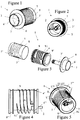
- FIGS 1 to 3 illustrate an in-line heater according to the machine of invention, Fig. 1 being a front perspective of the heater, Fig. 2 being a rear perspective of this heater and Fig. 3 being an exploded view of the same heater.
- the heater is suitable for a liquid food or beverage preparation machine, in which liquid is circulated through a heater and then guided into a brewing chamber for brewing a food or beverage ingredient supplied into the brewing chamber.
- a beverage ingredient is supplied to the machine in prepackaged form, for example contained in a capsule or in a pod.
- this type of liquid food or beverage machine is suitable to prepare coffee, tea and/or other hot beverages or even soups and like food preparations.
- the pressure of the liquid circulated to the brewing chamber may for instance reach about 10 to 20 atm.
- the heater has a body 1 incorporating an inlet 2, an outlet 3 and a helicoidal heating chamber 4 extending therebetween.
- Inlet 2, outlet 3 and heating chamber 4 forming together a rigid passage for guiding liquid circulating through body 1.
- the heater further includes a heating means 5 in the form a resistive thick-film that extends as a helicoidal track between two connector areas 5',5" over body 1 and cooperates with the body for supplying heat into heating chamber 4 located underneath thick-film 5.
- a heating means 5 in the form a resistive thick-film that extends as a helicoidal track between two connector areas 5',5" over body 1 and cooperates with the body for supplying heat into heating chamber 4 located underneath thick-film 5.
- Heater body 1 has an outer face 6 arranged to delimit an upstream part of a brewing chamber 7, the rigid passage, in particular outlet 3, of body 1 extending into brewing chamber 7. As shown schematically in Figures 1 and 3 , outer face 6 includes an annular protruding wall 6' for delimiting the upstream part of brewing chamber 7.
- body 1 has a generally tubular outer member 8 that is covered with the heating means 5.
- Member 8 has a thin wall made of thermally highly conductive material and of low inertia, such as steel, to promote transfer of heat generated by the heating means 5 formed thereon.
- This generally tubular outer member 8 cooperates with a base member that forms the outer face 6 of body 1.
- Outer face 6 is shown extending peripherally over the edge of tubular member 8. Moreover, annular wall 6' delimiting the upstream portion of brewing chamber 7, is generally coaxial with outlet 3 and has a diameter that is smaller than the diameter of tubular member 8.
- the upstream portion of brewing chamber 7 may be formed integrally with tubular member 8 and/or annular wall 6' may have an outermost surface that is co-extensive with the outer surface of tubular member 8 to further simplify its geometry.
- annular wall 6' may have an outermost surface that is co-extensive with the outer surface of tubular member 8 to further simplify its geometry.
- Body 1 of Figures 1 to 3 further includes an inner core 9, in particular a hollow tubular or cylindrical insert, with a peripheral protruding helicoidal guiding wall 91.
- Inner core 9 is generally coextensive and concentric with respect to tubular outer member 8, and delimits with outer member 8 helicoidal heating chamber 4.
- a helicoidal groove may be provided around the inner core instead of the protruding guiding wall.
- the groove or wall may also be formed on the inner face of the tubular outer member.
- Inner core 9 may be made of metal or of a material that is less heat conductive such as plastic or ceramic material.
- One or more electric components such as sensors and/or electric power elements, are secured in body 1 in a housing 3' located around outlet 3.
- the electric components may include one or more of: temperature sensors, thermal fuses, flow meters, resistive heaters and electric power regulators.
- Housing 3' and the therein contained electric components may be connected via rigid data transfer connectors to a printed circuit board (not shown).
- the electric components may be assembled into tubular outer member 8.
- the power element for instance a triac, for adjusting the electric current passed via the resistive heating means 5 may be located in the heater close to the circulating liquid so that the circulating liquid may serve as a cooler for the power component.
- sealing means 9' on insert 9 to prevent the leakage of liquid between tubular outer member 8 and insert 9.
- Sealing means 9' may be integral with tubular outer member 8 or insert 9 or a separate member 9' between member 8 and insert 9, such as an o-ring or another deformable seal, or a seam formed by welding.
- Heater body 1 has an inner core 9 which is generally coextensive and eccentric with respect to the tubular outer member 8.
- the helicoidal heating chamber 4 has variable cross-section around inner core 9.
- the cross-section 4' of heating chamber 4 is significantly smaller than the cross-section 4" along the opposite side of outer member 8 and insert 9.
- the heating power of heating means 5 may be reduced over a portion 5''' as indicated on Figure 5 by the notional generally rectangular section 5'''' intercepting heating element 5 on tubular outer member 9.
- Portion 5'''' may extend along tubular outer member 9 over an arc of about 15 to 90°, in particular 30 to 60° deg of the tubular outer member 9, as measured from the central longitudinal axis 8a of tubular member 8.
- FIG. 6 schematically shows another embodiment of a heater according to the invention.
- the heater's body 1 has a generally tubular outer steel member 8 and an insert in the form of a generally tubular plastic hollow inner core 9 with a peripheral helicoidal flange 91 that delimits with an inner surface of member 8 a helicoidal heating chamber 4 extending between inlet 2 and outlet 3.
- Flange 91 extends to an inner surface of tubular outer member 8 and contributes to position and secure properly insert 9 within outer member 8.
- tubular outer member 8 and inner core 9 are eccentric, as shown by their respective central axis 8a and 9a that extend side-by-side and parallel to one another, so that heating chamber 4 has a variable cross-section 4',4" along its length as discussed above.
- Tubular outer member 8 has a generally frust-conical outer front face 6 formed by protruding walls 6' delimiting an upstream part of a brewing chamber 7 with piercing elements 7' for opening a capsule 7" containing an ingredient to be extracted, in particular a beverage or food ingredient.
- Outlet 3 extends through outer member 8 into the upstream part of brewing chamber 8.
- tubular outer member 8 has an outer surface 8' that extends substantially continuously over heating chamber 4',4" and the upstream part of brewing chamber 7.
- Tubular outer member 8 and frusto-conical brewing chamber 7 are concentric along axis 8a.
- the end of outlet 3 that leads into brewing chamber 7 is also concentric with outer member 8 along axis 8a.
- outer surface 8' is covered with a resistive thick-film 5 as discussed above.
- Tubular insert 9 is secured within tubular outer member 8, for instance by gluing, screwing, welding, force fitting or any other appropriate assembly means.
- insert 9 has protrusions 92 that are fitted in corresponding recesses in tubular member 8.
- insert 9 has outer portions 93, for instance formed by small parallel side-by-side grooves or side-by-side protrusions, that my contain a bonding material such as glue and/or that may be compressed against outer member 8 to secure insert 9 therein.
- Insert 9 may also be urged and deformed in compression against inner surfaces of outer member 9 by using a structural element 94, in particular made of metal or ceramic material or another structural material that has a greater rigidity than insert 9, for instance in the form of a ring, that pushes a portion of insert 9 against outer member 8.
- a structural element 94 in particular made of metal or ceramic material or another structural material that has a greater rigidity than insert 9, for instance in the form of a ring, that pushes a portion of insert 9 against outer member 8.
- Inlet 2 is formed between outer member 8 and insert 9 and leads into heating chamber 4.
- the inlet may be located only in the outer member or in the insert.
- the outlet leading into the brewing chamber may exit from the insert or between the insert and the tubular outer member, instead of exiting from the tubular outer member 8 as shown in Figure 6 .
- inlet 2 is connected to the rigid outlet of a flow meter 75.
- the flow meter's outlet is secured to inlet 2 by way of a water-tight joint 76, typically an o-ring located in a corresponding annular groove 78 extending along an inner face 79 of the flow meter's outlet.
- a flow meter may be provided in or down stream the heating chamber, for instance at the outlet of the heating chamber, in particular integrated in the heater.
- the heater further comprises electric components 60,70 that are integrated, mechanically secured or rigidly assembled to heater body 1 and to a printed circuit board (PCB) 50, for instance as discussed below in greater details in connection with Figures 7 to 9 .
- electric component 60 may be a power component in the form of a triac for regulating the current supply to resistive thick-film heating element 5
- electric component 70 may be a temperature sensor for measuring the temperature of circulating liquid heated by the heater.
- the heater also includes a thermal fuse as a protection to avoid overheating of the heater.
- These electric components may be discrete components or integrated components, in particular integrated into the thick-film heating element 5.
- flow meter 75 and resistive heating means 5 are also rigidly connected to printed circuit board 50. In other words, they are electrically connected to printed circuit board 50 with a cableless connection. More specifically, power pins 11 are assembled to resistive heating means 5 at connector areas 5',5" and cooperate with socket 86 of a connector that is assembled to printed circuit board 50, for instance as discussed below in greater details in relation with Figures 11 to 13b .
- printed circuit board 50 is associated, with a micro-controller or processor 53 and a quartz clock 54 for controlling the intensity of current passed to resistive heating element 5 based on the flow rate of the circulating liquid measured with flow meter 75 and the temperature of the heated liquid measured with temperature sensor 70.
- a micro-controller or processor 53 may be incorporated into the heater and/or brewing chamber, in particular upstream the heater or at the heater's inlet 2.
- Controller or processor 53 may also control further functions of a beverage preparation machine into which the heater is located, such as a pump, a liquid level detector in a supply reservoir, a valve, a user interface, a power management arrangement, an automatic beverage ingredient supplier such as an integrated coffee grinder or an automatic supplier of ingredient capsules or pods, etc...
- a liquid to be heated is circulated, for instance by using a pump, via flow meter 75 and inlet 2, helicoidally through heating chamber 4 around insert 9, as indicated by arched arrows 15.
- the heated liquid is then guided via outlet 3 into brewing chamber 7, along piercing elements 7' through capsule 7" for brewing the ingredient contained therein.
- Controller 53 is arranged to control triac 60 for adjusting the heating current passed via socket 86 and power pins 11 to heating element 5, based on measures of the liquid flow by means of flowmeter 75 and of the temperature of the heated liquid by means of temperature sensor 70.
- Figures 7 and 8 illustrate the assembly of a discrete power component in the form of a triac 60 to a heater body 1 and a printed circuit board 50. Whereas Figure 7 shows the assembly in an exploded perspective view, Figure 8 discloses the assembly in cross-section.
- the heater body 1, a part of which is shown in Figures 7 and 8 has a recess 101 for receiving power component 60.
- Recess 101 formed between protruding walls 102 is associated with a spring element 103, for example in the shape of a spring leaf, assembled to body 1, e.g. via a screw 104.
- spring element 103 urges power component 60 against walls 102 of recess 101 in body 1 when component 60 is inserted into recess 101, to secure component 60 in body 1 and provide an optimal contact between body 1 and component 60.
- Power component 60 has one or more rigid electrical connector pins 61, for instance three pins for the triac shown in Figures 7 and 8 , which are rigidly connected to printed circuit board 50. Furthermore, the power element is covered with an optional cap 62, e.g. made of silicon, that may assist fixation of the power component 50 in recess 101, as well as an optional non conductive sleeve 63 around its connector pins 61 which spaces the main body of power component 60 from printed circuit board 50 and protect pins 61 against the environment. Cap 62 and sleeve 63 provide an electric insulation around power component 60.
- cap 62 and sleeve 63 provide an electric insulation around power component 60.
- the heater serves as a heat sinker for power component 60 by evacuating, via heater body 1 and optionally via liquid circulating through the heater, heat generated by the power component during use.
- the heater is made of materials, in particular metal, that allows optimal evacuation of heat from the power component along the heat evacuation path through the heater.
- Power component 60 may be a switch or regulating element, for instance a triac as mentioned above, to adjust the required electric power that is supplied to the resistive means, e.g. a thick-film, for generating the desired heat in the heater in order to heat the circulating liquid to the appropriate temperature.
- a switch or regulating element for instance a triac as mentioned above, to adjust the required electric power that is supplied to the resistive means, e.g. a thick-film, for generating the desired heat in the heater in order to heat the circulating liquid to the appropriate temperature.
- FIGS 9 and 10 illustrate the rigid assembly of a discrete electronic component 70 into a heater 1 and to a printed circuit board 50.
- This electronic component may be a sensor such as a temperature sensor, a flow meter, a thermal fuse or another similar component, such as an ammeter for providing a feedback of the current passed through the resistive heating means.
- a thermal sensor for the control of current passed to the heating means and adjustment of the heat generated is disclosed.
- the thermal sensor may for example be located at the heater's inlet, outlet or inbetween. Several thermal sensors may be used to allow a more precise control of the heating of the liquid passed via the heater.
- Heater body 1 a part or which is shown in Figures 9 and 10 has a recess 111 for receiving the electronic component 70.
- Recess 111 is formed between protruding walls 112 and extends below the surface of heater body 1.
- Sensor 70 has a connector socket 71 through which a sensor element 72 is joined to electric flat connectors (not shown) on the opposite side of socket 71.
- the sensor's connection pins are brought into contact with flat connector pins 51, one of which is shown in Figure 10 , of printed circuit board 50.
- Pins 51 extend through a plug member 52 of board 50, to which connector socket 71 is mechanically connected, into socket 71 for contacting the corresponding connection pins of sensor 70.
- sensor 70 When sensor 70 is a temperature sensor, the electric characteristics of sensor element 72 will depend on the temperature in recess 111, which will be used for evaluating the temperature of the heater at this location and optionally also the temperature of nearby circulating liquid in an indirect evaluation process.
- Sensor element 72 may for instance be an NTC (negative temperature coefficient) resistor or a PTC (positive temperature coefficient) resistor.
- Such a sensor configuration permits reliably measuring the temperature in the corresponding location of the heater, fast reaction (low inertia) and provides an excellent and reliable electric contact system.
- Sensor 70 may be preassembled into socket 71, for instance made of thermoplastic material, and automatically assembled into a heater and to a printed circuit board in a fully automatic process. Sensor 70 may be glued into the heater using for example an epoxy compound. The preassembled sensor 70 may then be connected by pressing the socket's flat connectors into connection slots (not shown) of socket 71 in such a way as to be connected to sensor element 72. Printed circuit board 50 is then mounted onto socket 70 via plug 52 and connector pins 51.
- the assembly itself of the heater and the printed circuit board does not require handling any flexible parts and thus the assembly can be carried automatically without the need of any human intervention. Furthermore, the assembly of the sensor itself only requires low cost components. Hence, the assembly of the sensor on a heater and its connection to a printed circuit board leads to significant cost savings.
- electric components such as temperature sensors may be directly formed in thick-film technology in the heater. This is particularly advantageous for reducing the manufacturing steps and costs when the heating means is based on thick-film technology.
- Figure 11 is a perspective view in an xyz orthogonal referential, as indicated by the corresponding arrows associated with Figures 11 to 13b , of a self-positioning rigid electric power connector 80 for connecting a heater to a printed circuit board 50 and for carrying heating current to or from the heater's resistive heating means.
- Power connector 80 is typically metal-based, and may in particular contain steel, aluminium and/or copper alloys that provide sufficient electric conductivity, mechanical resistance and resilience.
- Power connector 80 extends between a pair of flat feet 81 for connection to a printed circuit board 50.
- Each foot 81 is connected to a bottom part of a flat generally upright spring member 82.
- the upper parts of the upright spring blades 82 are connected together via a transverse spring member 83 that comprises a flat central horizontal part 84 inbetween a pair of inclined intermediate parts 85,85'.
- Upright members 82, intermediate part 84 and inclined parts 85,85' of transverse member 83 are in a general M arrangement on the pair of feet 81.
- Transverse member 83 further includes a socket 86 with a through-passage for securing therethrough an electric connector pin from the heater.
- a power connector 80 is schematically shown assembled via a power pin 11 onto a tubular outer member 8 of a heater body 1 with an inlet 2.
- Power pin 11 extends upright at the beginning of tubular outer member 8 and is connected to connection area of resistive heating means (not shown) extending over the tubular outer member 8, the other connection area of the resistive heating means being connected via a second power pin to a second power connector (not shown).
- Power pin 11 extends through and is secured in the through-passage of socket 86 of transverse member 83.
- Feet 81 of power connector 80 are electrically connected and secured onto printed circuit board 50, for instance by rivets or welding 81' or any other suitable assembly means.
- Heater body 1 is located underneath printed circuit board 50 so that power pin 11 extends through board 50 via a through-opening 55 in board 50 to the other side of board 50 and is then secured in through-passage 86 of power connector 80.
- Continuous electrical connection between power pin 11 and transverse member 83 may be achieved by force-fitting or welding pin 11 in through-passage 86.
- Power connector 80 allows for small positioning displacements of through-passage 86 in the x direction and y direction, with reference to the xyz referential associated with Figs. 11 to 13b .
- Different directions of displacements are provided by the different orientations, in particular perpendicular orientations, of the resilient spring blade members 82,83, which permit displacements along corresponding directions.
- Figures 12a and 12b on the one hand, and Figures 13a and 13b , on the other hand, show a displacement of the connector's socket 86 assembled to power pin 11 along the y direction and the x direction respectively. Displacement of socket 86 in the x and y directions is achieved by a small flexion of upright spring blades 82 and a small flexion of inclined intermediate parts 85,85', respectively.
- Figures 12a and 13a show power pin 11 extending right through the middle of through-opening 55, and through the through-passage of socket 86 which all extend along substantially the same axis.
- power pin 11 is positioned in line with power connector 80 which is thus not subjected to any displacement flexion stress in its upright spring blades 82 and inclined intermediate parts 85,85'.
- FIGS 12b and 13b show power pin 11 extending eccentrically through through-opening 55.
- Through-passage of socket 86 aligned to power pin 11 is equally eccentric with respect to through-opening 55.
- printed circuit board 50 is not perfectly aligned with power pin 11 of the heater and the power connector 80 self-adapts the position of its through-passage in socket 86 to match precisely the position of pin 11 by flexion of its upright spring blades 82 in the x direction, as shown in Figure 13b , or by flexion of its transverse spring member 83 in the y direction, as shown in Figure 12b .
- the lower part 86' of socket 86 has a generally funnel-like or frusto-conical shape that is arranged to receive a generally conical upper end of power pin 11.
- the displacement of socket 86 to adapt to the position of power pin 11 may result from discrepancies, e.g. manufacturing tolerances or different temperature-related dilatation mechanisms, between the relative positioning of a pair of power connectors 80 on printed circuit board 50 with respect to the relative positioning of a corresponding pair of power pins 11 on the heater.
- the relative position of other electrical components that are rigidly connected to the printed circuit board and fixed parts of the beverage preparation machine, in particular the heater may induce displacements at the level of the power connection.
- first power connector 80 During use, the passage of current via first power connector 80, first power pin 11, the resistive heating means (not shown), the second power pin (not shown), the second power connector (not shown) is controlled by a power switch or regulator, e.g. a triac, for instance as shown in Figures 7 and 8 .
- a power switch or regulator e.g. a triac, for instance as shown in Figures 7 and 8 .
- Figures 12a and 12b also illustrate how an error of relative positioning of feet 81 and inclined parts 85,85' on printed circuit board 50 is managed by power connector 80.
- feet 81 and thus inclined parts 85,85' are not perfectly aligned in the x direction but slightly off-set one to another. This off-set is however fully compensated by a corresponding resilient deflection of transverse member 83 without causing excessive stress in printed circuit board 50 or in power connector 80.
- FIGS 14 and 15 in which the same numeric references designate generally the same elements, schematically disclose two alternative embodiments of a beverage or liquid food machine with a user-reversible fuse device.
- the machine according to the invention has an electric supply circuit 57 that is connectable to a power source (not shown), such as the mains or an equivalent power source.
- Supply circuit 57 is connected to a printed circuit board (PCB) 50 which bears the machine's control unit, e.g. a micro-controller, memory device, various interfaces to the various parts of the machine that require automatic control, such as a user-interface, a pump, a heater 1, sensors 60,70, etc...
- Supply circuit 57 has a main switch 205,205' allowing a user to switch on and off the beverage or liquid food machine.
- main switch 205,205' is mechanically mounted onto PCB 50 to facilitate assembly and increase integration of the system.
- the machine includes a thermal fuse device 200 that has a switch 205 on circuit 57 and an actuator 201,201' arranged to disconnect circuit 57 by actuating switch 205 when heater 1 has a temperature that exceeds a temperature limit, e.g. a temperature limit in the range of 120°C to 180°C, in particular 140°C to 160°C, indicative of a malfunction of heater 1 or of its control unit 50.
- a temperature limit e.g. a temperature limit in the range of 120°C to 180°C, in particular 140°C to 160°C, indicative of a malfunction of heater 1 or of its control unit 50.
- Thermal fuse device 200 is user reversible. Upon safety disconnection of circuit 57 by fuse device 200, switch 205 may be operated by a user to reconnect circuit 57 and re-establish electric powering of the PCB. Hence, if thermal fuse device 200 goes off improperly or if heater 1 merely has an accidental one time overheat condition, the liquid food or beverage machine of the invention does not need to be returned for servicing in order to replace the fuse device, unlike existing beverage or liquid food machines fitted with one time thermal fuses.
- Fuse device 200 has an actuator 201,201' that is arranged to push out a pin, rod or piston 202 against the user switch, e.g. a switch of the push-button type, when said temperature limit is exceeded by the heater so as to actuate the user switch and open circuit 57.
- the user switch e.g. a switch of the push-button type
- thermo-mechanical component may be any arrangement suitable to convert the passage of a temperature level into a mechanical action or displacement, such as an element made of a shape memory alloy that remembers its shape, or a bi-metal element.
- thermo-mechanical component of actuator 201 when heater 1 exceeds the temperature limit, the thermo-mechanical component of actuator 201 is activated and will urge pin 202 against user switch 205. This will disconnect the electric parts of the machine from the power supply connected to circuit 57.
- the thermo-mechanical component When the heater's temperature drops below the temperature limit, the thermo-mechanical component will return back into its normal state and pin 202 will either follow the thermo-mechanical component or may be pushed back into its normal position by a user who actuates switch 205 to re-establish the power connection of the machine.
- the user switch 205 cooperating with the thermal fuse may also serve as a main switch that may be operated independently of any over-heat situation in order to ordinarily switch on and off the beverage or liquid food machine.
- the user switch 205 cooperating with the thermal fuse is a dedicated switch separate from the main switch 205'.
- Fuse device 200 comprises a safety electric temperature sensor 203 mechanically mounted against heater 1 and in thermal communication therewith. Furthermore, to simplify assembly and further integrate the electric components of the machine, temperature sensor 203 is rigidly connected to PCB 50 in a similar manner as discussed above. Temperature sensor 203 monitors the temperature of heater 1. In a less preferred embodiment, such a temperature sensor may also be connected by other means to the PCB, in particular in a partly or entirely flexible manner.
- Temperature sensor 203 is associated with a control means that controls the electrical powering of actuator 201' via its connection circuit 204 depending on the measured temperature.
- the control means includes a power switch, e.g. a transistor, on connection circuit 204 connected to temperature sensor 203.
- the temperature sensor 203, the power switch associated therewith, user switches 205 and even actuator 201' are rigidly mounted onto PCB 50.
- these components are mounted on a section 50' of PCB 50 that is electrically insulated from the ordinary control unit of the beverage and liquid food machine on PCB 50.
Claims (13)
- Machine de préparation d'aliment liquide ou de boisson comprenant une pompe, un dispositif de chauffage en ligne et une chambre à infusion (7) destinée à faire circuler du liquide à travers le dispositif de chauffage vers la chambre à infusion sous pression, en particulier à une pression d'environ 1 à 2 MPa (environ 10 à 20 Atm), pour faire infuser un ingrédient d'aliment ou de boisson introduit dans ladite chambre à infusion (7), ce dispositif de chauffage comprenant :- un corps (1) comprenant une entrée (2), une sortie (3) et une chambre de chauffage (4, 4', 4") s'étendant entre celles-ci, lesdites entrée, sortie et chambre de chauffage formant ensemble un passage rigide (2, 3, 4, 4', 4") destiné à guider ledit liquide circulant sous pression à travers ledit corps ; et- un moyen de chauffage (5), en particulier un moyen de chauffage à résistance tel qu'un circuit à couche épaisse, coopérant avec le corps (1) pour fournir de la chaleur dans ladite chambre de chauffage (4, 4', 4"),dans laquelle ledit corps (1) présente une face externe (6) agencée de façon à délimiter une partie amont de la chambre à infusion (7), le passage rigide (2, 3, 4, 4', 4") du corps s'étendant à l'intérieur de la chambre à infusion (7),
caractérisée en ce que ledit corps comprend un élément externe globalement tubulaire ou prismatique qui est recouvert par ledit moyen de chauffage. - Machine selon la revendication 1, dans laquelle la face externe du corps inclut une ou plusieurs parois en saillie pour délimiter la partie amont d'une chambre à infusion ; et/ou un moyen de raccordement permettant un raccordement mécanique à un élément délimitant une partie aval de la chambre à infusion.
- Machine selon la revendication 1 ou 2, dans laquelle l'élément externe globalement tubulaire ou prismatique présente une base qui forme ladite face externe du corps, et éventuellement l'élément externe globalement tubulaire ou prismatique présente une inertie thermique inférieure à celle de l'aluminium.
- Machine selon une quelconque revendication précédente, dans laquelle le corps inclut en outre un noyau interne, en particulier un insert qui délimite, avec l'élément externe, la chambre de chauffage, le noyau interne étant éventuellement globalement confondu avec, et/ou globalement concentrique par rapport à, l'élément externe tubulaire ou prismatique.
- Machine selon la revendication 4, dans laquelle la chambre de chauffage est globalement hélicoïdale autour du noyau, en particulier une chambre formée par une rainure ou une bride globalement hélicoïdale autour du noyau.
- Machine selon la revendication 4 ou 5, dans laquelle le noyau interne est globalement excentrique par rapport à l'élément externe tubulaire ou prismatique.
- Machine selon une quelconque revendication précédente, dans laquelle un ou plusieurs composants électriques sont fixés sur ou dans le corps du dispositif de chauffage, les composants électriques étant en particulier choisis parmi des capteurs de température, des fusibles thermiques, des débitmètres, des dispositifs de chauffage à résistance, des ampèremètres et des régulateurs d'alimentation électrique.
- Machine selon la revendication 7, dans laquelle ledit ou lesdits composants électriques sont connectés rigidement à une carte de circuit imprimé agencée pour commander ledit dispositif de chauffage et éventuellement d'autres fonctions de ladite machine, telles que la pompe, une interface électrique, une interface utilisateur, un agencement de gestion d'alimentation, un distributeur automatique d'ingrédients de boissons comme un moulin à café intégré ou un distributeur automatique de capsules ou de dosettes d'ingrédient.
- Machine selon la revendication 8, dans laquelle ledit ou lesdits composants électriques (5, 60, 70, 75) sont connectés rigidement à ladite carte de circuit imprimé (50) par le biais de broches ou de lames de connecteur rigides ou d'éléments de fiche et de prise rigides.
- Machine selon la revendication 9, dans laquelle ledit ou lesdits composants électriques comprennent un composant de puissance, en particulier un moyen de chauffage à résistance tel qu'un circuit à couche épaisse, qui est rigidement connecté par l'intermédiaire d'une broche d'alimentation électrique rigide et d'un connecteur d'alimentation rigide qui comporte une prise pour recevoir la broche électrique rigide, le connecteur rigide étant élastique, constitué en particulier d'une ou plusieurs lames de ressort, pour permettre des déplacements de la prise pour l'auto-positionnement de la prise autour de la broche et pour assurer le contact électrique entre la broche et le connecteur.
- Machine selon une quelconque revendication précédente, qui comprend :- un circuit d'alimentation électrique (57) pouvant être connecté à une source d'alimentation électrique, le dispositif de chauffage étant alimenté par le circuit d'alimentation électrique ; et- un dispositif de fusible thermique (200) en communication thermique avec le dispositif de chauffage et associé au circuit d'alimentation électrique, le dispositif de fusible étant agencé de manière à couper le circuit d'alimentation électrique provenant de ladite source d'alimentation lorsque la température du dispositif de chauffage dépasse une limite de température,dans laquelle le dispositif de fusible thermique (200) est réversible et comprend un interrupteur (205) pour couper automatiquement le circuit d'alimentation électrique lorsque la température du dispositif de chauffage dépasse ladite limite de température, l'interrupteur pouvant être actionné par un utilisateur pour fermer le circuit d'alimentation électrique lorsque la température du dispositif de chauffage est redescendue sous ladite limite de température, le dispositif de fusible comprenant en particulier un actionneur (201) qui est agencé pour faire sortir une broche, une tige ou un piston (202) contre l'interrupteur d'utilisateur lorsque la température du dispositif de chauffage dépasse ladite température limite, de manière à actionner l'interrupteur d'utilisateur et ouvrir le circuit (57).
- Machine selon la revendication 11, dans laquelle le dispositif de fusible (200) comporte :- un actionneur (201) qui comprend un composant thermomécanique qui est en communication thermique avec le dispositif de chauffage (1) et qui actionne mécaniquement l'interrupteur d'utilisateur (205) pour ouvrir le circuit d'alimentation électrique (57) lorsque la température du dispositif de chauffage dépasse la limite de température, le composant thermomécanique comprenant en particulier un élément à mémoire de forme ou un élément bimétallique ; et/ou- un capteur de température électrique de sécurité (203) en communication thermique avec le dispositif de chauffage (1) et un actionneur électromécanique (201') qui actionne l'interrupteur d'utilisateur (205) pour ouvrir le circuit d'alimentation électrique (57) lorsque le capteur de sécurité (203) est exposé à une température générée par le dispositif de chauffage qui dépasse la limite de température.
- Utilisation d'une machine selon une quelconque revendication précédente pour faire infuser un ingrédient d'aliment ou de boisson qui est contenu dans une capsule ou une dosette.
Priority Applications (1)
| Application Number | Priority Date | Filing Date | Title |
|---|---|---|---|
| EP10161827.0A EP2218374B1 (fr) | 2007-10-04 | 2008-09-30 | Unité de préparation de boisson |
Applications Claiming Priority (4)
| Application Number | Priority Date | Filing Date | Title |
|---|---|---|---|
| EP07117853 | 2007-10-04 | ||
| EP08154918 | 2008-04-22 | ||
| EP10161827.0A EP2218374B1 (fr) | 2007-10-04 | 2008-09-30 | Unité de préparation de boisson |
| EP08834770.3A EP2209407B1 (fr) | 2007-10-04 | 2008-09-30 | Unité de préparation de boisson |
Related Parent Applications (3)
| Application Number | Title | Priority Date | Filing Date |
|---|---|---|---|
| EP08834770.3A Division-Into EP2209407B1 (fr) | 2007-10-04 | 2008-09-30 | Unité de préparation de boisson |
| EP08834770.3A Division EP2209407B1 (fr) | 2007-10-04 | 2008-09-30 | Unité de préparation de boisson |
| EP08834770.3 Division | 2008-09-30 |
Publications (3)
| Publication Number | Publication Date |
|---|---|
| EP2218374A2 EP2218374A2 (fr) | 2010-08-18 |
| EP2218374A3 EP2218374A3 (fr) | 2015-05-20 |
| EP2218374B1 true EP2218374B1 (fr) | 2017-12-27 |
Family
ID=40342582
Family Applications (5)
| Application Number | Title | Priority Date | Filing Date |
|---|---|---|---|
| EP10161821.3A Not-in-force EP2218371B1 (fr) | 2007-10-04 | 2008-09-30 | Appareil de préparation de boisson ou de nourriture liquide |
| EP10161826.2A Active EP2218373B1 (fr) | 2007-10-04 | 2008-09-30 | Dispositif de chauffage intégré pour un dispositif de préparation de boisson |
| EP10161827.0A Active EP2218374B1 (fr) | 2007-10-04 | 2008-09-30 | Unité de préparation de boisson |
| EP10161825.4A Active EP2218372B1 (fr) | 2007-10-04 | 2008-09-30 | connecteur électrique d'unité de préparation de boisson |
| EP08834770.3A Active EP2209407B1 (fr) | 2007-10-04 | 2008-09-30 | Unité de préparation de boisson |
Family Applications Before (2)
| Application Number | Title | Priority Date | Filing Date |
|---|---|---|---|
| EP10161821.3A Not-in-force EP2218371B1 (fr) | 2007-10-04 | 2008-09-30 | Appareil de préparation de boisson ou de nourriture liquide |
| EP10161826.2A Active EP2218373B1 (fr) | 2007-10-04 | 2008-09-30 | Dispositif de chauffage intégré pour un dispositif de préparation de boisson |
Family Applications After (2)
| Application Number | Title | Priority Date | Filing Date |
|---|---|---|---|
| EP10161825.4A Active EP2218372B1 (fr) | 2007-10-04 | 2008-09-30 | connecteur électrique d'unité de préparation de boisson |
| EP08834770.3A Active EP2209407B1 (fr) | 2007-10-04 | 2008-09-30 | Unité de préparation de boisson |
Country Status (18)
| Country | Link |
|---|---|
| US (2) | US8600223B2 (fr) |
| EP (5) | EP2218371B1 (fr) |
| JP (1) | JP2010540132A (fr) |
| KR (1) | KR20100065200A (fr) |
| CN (5) | CN102133048B (fr) |
| AR (1) | AR068676A1 (fr) |
| AU (1) | AU2008306932A1 (fr) |
| CA (1) | CA2701664A1 (fr) |
| CL (1) | CL2008002965A1 (fr) |
| ES (2) | ES2619715T3 (fr) |
| IL (1) | IL204831A0 (fr) |
| MX (1) | MX2010003569A (fr) |
| PT (2) | PT2218371T (fr) |
| RU (2) | RU2506030C2 (fr) |
| SG (1) | SG184782A1 (fr) |
| TW (1) | TW200938139A (fr) |
| WO (1) | WO2009043851A2 (fr) |
| ZA (1) | ZA201003080B (fr) |
Families Citing this family (76)
| Publication number | Priority date | Publication date | Assignee | Title |
|---|---|---|---|---|
| EP1495702A1 (fr) * | 2003-07-10 | 2005-01-12 | Nestec S.A. | Dispositif pour l'extraction d'une capsule |
| ITBO20070420A1 (it) * | 2007-06-15 | 2008-12-16 | B F Gaggio Di Bonanno Francesc | Gruppo perfezionato per macchine per caffe' espresso |
| US8600223B2 (en) | 2007-10-04 | 2013-12-03 | Nestec S.A. | Integrated heater for a beverage preparation device |
| CL2008002963A1 (es) | 2007-10-04 | 2010-01-22 | Nestec Sa | Dispositivo calentador para una maquina para la preparacion de alimento liquido o bebida, que comprende una unidad termica con una masa metalica, a traves de la cual circula el liquido, y acumula calor y lo suministra al liquido, y tiene uno o mas componentes electricos asegurados en forma rigida a la unidad termica; y maquina. |
| CN103181729B (zh) | 2007-10-04 | 2016-01-20 | 雀巢产品技术援助有限公司 | 饮料冲煮单元 |
| JP2011508738A (ja) * | 2007-12-26 | 2011-03-17 | バイオテスト・アクチエンゲゼルシヤフト | Cd138発現腫瘍細胞のターゲティングを向上させる方法及び剤 |
| CA2716756A1 (fr) * | 2008-04-22 | 2009-10-29 | Nestec S.A. | Assemblage modulaire d'une machine a preparer des boissons |
| CN102118992B (zh) | 2008-08-08 | 2014-12-03 | 雀巢产品技术援助有限公司 | 带有携带手柄和可配置的外观及侧面功能的饮料机 |
| US8863648B2 (en) | 2009-03-23 | 2014-10-21 | Nestec S.A. | Pump mount in a beverage preparation machine |
| FR2944419A1 (fr) * | 2009-04-21 | 2010-10-22 | Cie Mediterraneenne Des Cafes | Chaudiere pour machine de preparation de boissons |
| JP2011074846A (ja) * | 2009-09-30 | 2011-04-14 | Keihin Corp | Ptcヒータユニットおよびlpg燃料用減圧弁 |
| RU2571172C2 (ru) | 2009-12-01 | 2015-12-20 | Нестек С.А. | Соединение расходомера и печатной платы в устройстве для приготовления напитков |
| FR2956309B1 (fr) * | 2010-02-15 | 2012-07-20 | Seb Sa | Chaudiere rapide et appareil electromenager comprenant une telle chaudiere |
| WO2011107574A2 (fr) | 2010-03-05 | 2011-09-09 | Nestec S.A. | Réduction de problèmes de pompe |
| FR2960405B1 (fr) * | 2010-05-25 | 2013-01-18 | Cie Mediterraneenne Des Cafes | Dispositif d'infusion a variation de pression |
| EP2582274B1 (fr) | 2010-06-17 | 2014-04-30 | Nestec S.A. | Chauffage rapide d'un dispositif de conditionnement thermique, par exemple pour une machine à café |
| JP6018054B2 (ja) | 2010-07-16 | 2016-11-02 | ネステク ソシエテ アノニム | 高性能加熱装置 |
| KR20130121917A (ko) | 2010-12-02 | 2013-11-06 | 네스텍 소시에테아노님 | 음료 기계의 저관성 열 센서 |
| EP2688449B1 (fr) | 2011-03-23 | 2018-09-26 | Nestec S.A. | Machine à boisson ayant un couvercle pour un dispositif d'admission des ingrédients |
| USD677510S1 (en) | 2011-06-16 | 2013-03-12 | Calphalon Corporation | Coffee maker |
| CA2845399A1 (fr) | 2011-09-16 | 2013-03-21 | Nestec S.A. | Element d'accouplement securise pour machine a boissons multi-systeme |
| JP2014526325A (ja) | 2011-09-16 | 2014-10-06 | ネステク ソシエテ アノニム | 清浄なマルチシステム飲料マシン |
| CN103781389A (zh) | 2011-09-16 | 2014-05-07 | 雀巢产品技术援助有限公司 | 多系统饮料机多重连接 |
| ITRE20110109A1 (it) * | 2011-12-07 | 2013-06-08 | Redox S R L | Macchina da caffe' a risparmio energetico |
| CN104023601B (zh) | 2011-12-30 | 2016-11-16 | 雀巢产品技术援助有限公司 | 多系统饮料机 |
| US9371841B2 (en) | 2012-03-05 | 2016-06-21 | Electrolux Home Products, Inc. | Safety arrangement for an integrated heater, pump, and motor for an appliance |
| JP2015534486A (ja) | 2012-10-09 | 2015-12-03 | ネステク ソシエテ アノニム | 原料カプセル取付装置を備えた飲料機 |
| KR20150083913A (ko) * | 2012-11-14 | 2015-07-20 | 그라코 미네소타 인크. | 펌핑 시스템을 위한 유체 가열기 |
| FR2999066B1 (fr) * | 2012-12-12 | 2017-09-01 | Cie Mediterraneenne Des Cafes | Chaudiere pour machine de preparation de boisson |
| DE102013201181A1 (de) * | 2013-01-24 | 2014-07-24 | BSH Bosch und Siemens Hausgeräte GmbH | Dickschichtheizung und Adapter dafür |
| RU2666297C2 (ru) * | 2013-03-20 | 2018-09-06 | Конинклейке Филипс Н.В. | Устройство для приготовления горячих напитков с механизмом автоматического снижения энергопотребления |
| DE102013207182A1 (de) | 2013-04-19 | 2014-10-23 | BSH Bosch und Siemens Hausgeräte GmbH | Verfahren zur Steuerung eines Heißgetränkezubereitungsgeräts |
| US10285536B2 (en) * | 2013-07-17 | 2019-05-14 | Nestec S.A. | Food or beverage preparation machine with antiscaling pipe system |
| EP3079531B1 (fr) | 2013-12-11 | 2019-02-06 | Nestec S.A. | Machine de boissons avec grille de capsule pivotante |
| US9307860B2 (en) | 2014-02-14 | 2016-04-12 | Remington Designs, Llc | Processor control of solute extraction system |
| WO2015155145A1 (fr) | 2014-04-08 | 2015-10-15 | Nestec S.A. | Manipulation de capsules de tailles multiples à actionnement séquentiel |
| WO2016005350A1 (fr) | 2014-07-09 | 2016-01-14 | Nestec S.A. | Dispositif permettant de raccorder une machine à boissons à un réseau de distribution avec surveillance en toute sécurité |
| WO2016005349A1 (fr) | 2014-07-09 | 2016-01-14 | Nestec S.A. | Accessoire permettant d'alimenter automatiquement une machine à boissons en liquide à partir d'un réseau de distribution |
| EP3166458B1 (fr) | 2014-07-09 | 2021-05-05 | Société des Produits Nestlé S.A. | Couplage d'un dispositif de raccordement d'une machine à boisson à un réseau de distribution |
| ES2828253T3 (es) | 2014-07-09 | 2021-05-25 | Nestle Sa | Dispositivo para conectar una máquina de bebidas a una red de distribución con interrupción segura de flujo |
| BR112017004206A2 (pt) * | 2014-09-05 | 2017-12-12 | Tuttoespresso Srl | aparelho de preparação de bebida e método para preparar uma bebida |
| CN106998940B (zh) | 2014-11-27 | 2020-04-28 | 雀巢产品有限公司 | 具有紧凑液滴止挡件的液体分配机器 |
| EP3223669B1 (fr) | 2014-11-27 | 2020-02-19 | Société des Produits Nestlé S.A. | Machine de distribution de liquide avec butée de gouttes manuelle |
| DE102015000491A1 (de) * | 2015-01-12 | 2016-07-14 | Holger Dreißig | Brühgruppe für Kaffee/Espressomaschinen, die es ermöglicht die Brühtemperatur genau zu steuern bzw. über die Bezugsdauer stabiler zu halten und den anfänglichen Druckanstieg zu dämpfen. |
| ITUB20150258A1 (it) * | 2015-02-25 | 2016-08-25 | La Marzocco Srl | Gruppo di erogazione di acqua calda per una macchina per caffè espresso o simile e relativa macchina |
| EP3902372A3 (fr) * | 2015-10-16 | 2022-02-23 | Breville USA, Inc. | Circulateur d'immersion thermique |
| JP6910352B2 (ja) | 2015-11-11 | 2021-07-28 | ソシエテ・デ・プロデュイ・ネスレ・エス・アー | 飲料マシンへの液体タンクの容易な接続 |
| CN105571109B (zh) * | 2016-02-05 | 2018-11-30 | 佛山市云米电器科技有限公司 | 一种水道加热装置的密封体 |
| CN105546804B (zh) * | 2016-02-05 | 2019-03-22 | 佛山市云米电器科技有限公司 | 一种用于液体加热的加热装置 |
| EP3238582A1 (fr) * | 2016-04-26 | 2017-11-01 | SAGA COFFEE S.p.A. | Unité d'infusion et dispositif de production de boisson comprenant une telle unité |
| US20170354290A1 (en) * | 2016-06-13 | 2017-12-14 | Curt Jones | Preparation of Heated Beverages |
| CA3034163A1 (fr) | 2016-10-11 | 2018-04-19 | Nestec S.A. | Machine de distribution de liquide a regulateur de vitesse |
| WO2018069266A1 (fr) | 2016-10-11 | 2018-04-19 | Nestec Sa | Machine de distribution de liquide à dispositif d'arrêt de goutte |
| CN109922668B (zh) | 2016-11-09 | 2023-03-31 | 百事可乐公司 | 碳酸饮料制备机、方法和系统 |
| US11428437B2 (en) | 2017-01-20 | 2022-08-30 | Bunn-O-Matic Corporation | Instant-response on-demand water heater |
| CN110312453A (zh) | 2017-02-28 | 2019-10-08 | 雀巢产品有限公司 | 具有平行分配路径的分配器 |
| CN106667271A (zh) * | 2017-03-01 | 2017-05-17 | 深圳鼎加弘思饮品科技有限公司 | 饮品机的温度补偿装置及其控制方法和饮品机 |
| KR101762094B1 (ko) * | 2017-04-04 | 2017-07-26 | 김이태 | 난방필름전용 전원커넥터 |
| PL3398487T3 (pl) * | 2017-05-03 | 2022-06-06 | Cup&Cino Kaffeesystem-Vertrieb Gmbh & Co. Kg | Sposób i urządzenie do wytwarzania pianki mlecznej |
| DE102017207738A1 (de) * | 2017-05-08 | 2018-11-08 | Mahle International Gmbh | Elektrische Heizeinrichtung |
| IT201700060931A1 (it) * | 2017-06-05 | 2018-12-05 | Lavazza Luigi Spa | Riscaldatore per fluidi e corrispondente macchina |
| US11866318B2 (en) | 2017-12-20 | 2024-01-09 | Societe Des Produits Nestle S.A. | Beverage preparation machine with handy drop stop |
| JP7308199B2 (ja) | 2017-12-20 | 2023-07-13 | ソシエテ・デ・プロデュイ・ネスレ・エス・アー | 泡を微細化する飲料調製マシン |
| AU2018387159A1 (en) | 2017-12-20 | 2020-05-07 | Societe Des Produits Nestle S.A. | Beverage preparation machine with drop evacuation |
| EP3752031A1 (fr) | 2018-02-14 | 2020-12-23 | Société des Produits Nestlé S.A. | Réceptacle de capsules usagées pour machines à boisson |
| CN110301826A (zh) * | 2018-03-20 | 2019-10-08 | 广州胜维电器制造有限公司 | 发热部 |
| RU183968U1 (ru) * | 2018-03-27 | 2018-10-11 | Николай Юрьевич Кулагин | Электрический нагреватель газовых и жидких сред |
| JP7079480B2 (ja) * | 2018-05-28 | 2022-06-02 | 株式会社松井製作所 | 金型温度制御装置及び金型温度制御方法 |
| EP3855988A1 (fr) | 2018-09-27 | 2021-08-04 | Société des Produits Nestlé S.A. | Unité de service adaptative d'une machine à boisson |
| EP3628195A1 (fr) | 2018-09-27 | 2020-04-01 | Société des Produits Nestlé S.A. | Machine de préparation de boissons avec détection de récipient |
| DE102018216733A1 (de) * | 2018-09-28 | 2020-04-02 | Robert Bosch Gmbh | Durchlauferhitzer |
| FR3087966B1 (fr) * | 2018-10-26 | 2021-08-20 | Valeo Equip Electr Moteur | Bloc de commande d'une machine electrique tournante et procede de montage d'un tel bloc de commande |
| IT201900001623A1 (it) | 2019-02-05 | 2020-08-05 | La Marzocco Srl | Macchina macina caffè con sistema di dosatura perfezionato e relativo metodo |
| WO2020201962A1 (fr) * | 2019-03-29 | 2020-10-08 | Carimali S.P.A. | Chauffe-eau à écoulement continu à induction électromagnétique dans une machine de préparation de boisson automatique |
| CN110567218A (zh) * | 2019-08-22 | 2019-12-13 | 安徽省宁国市天成电机有限公司 | 一种冰箱用加热器 |
| CN113865077B (zh) * | 2021-09-15 | 2022-11-18 | 珠海格力电器股份有限公司 | 加热件安装机构和净饮机 |
Citations (16)
| Publication number | Priority date | Publication date | Assignee | Title |
|---|---|---|---|---|
| US2514360A (en) | 1946-03-27 | 1950-07-11 | Octavio J Alvarez | Fluid heating device |
| FR1358502A (fr) | 1963-03-04 | 1964-04-17 | Perfectionnements aux cafetières | |
| US3423209A (en) | 1965-11-23 | 1969-01-21 | Robert L Weber | Brewing selectable variable quantities of coffee |
| FR2067808A5 (fr) | 1969-11-18 | 1971-08-20 | Stasse Roland | |
| US3898428A (en) | 1974-03-07 | 1975-08-05 | Universal Oil Prod Co | Electric in line water heating apparatus |
| US4759274A (en) | 1985-12-14 | 1988-07-26 | Melitta-Werke Bentz & Sohn | Coffee maker |
| EP0299146A2 (fr) | 1987-07-11 | 1989-01-18 | Robert Krups GmbH & Co. KG | Machine électrique pour faire des boissons chaudes, comme du café ou du thé |
| US4888466A (en) | 1987-07-11 | 1989-12-19 | Robert Krups Stiftung & Co. Kg. | Machine for making hot tea |
| DE19737694C1 (de) | 1997-08-29 | 1998-10-29 | August Balke Elektro Geraete G | Durchlauferhitzer für fließfähige oder pastöse, eßbare oder trinkbare Zubereitungen |
| DE19732414A1 (de) | 1997-07-30 | 1999-02-04 | Suhl Elektro & Hausgeraetewerk | Durchlauferhitzer mit Dickschichtheizelementen |
| EP0784955B1 (fr) | 1996-01-16 | 1999-06-02 | ESSEGIELLE S.r.l | Machine à café espresso |
| US6062127A (en) | 1999-08-13 | 2000-05-16 | Klosinski; Boguslaw | Portable espresso maker |
| WO2001054551A1 (fr) | 2000-01-24 | 2001-08-02 | Societe Des Produits Nestle S.A. | Module de rechauffement de liquide, systeme comprenant ledit module et procede de rechauffement de liquide |
| WO2004006742A1 (fr) | 2002-07-12 | 2004-01-22 | Nestec S.A. | Dispositif permettant de chauffer un liquide |
| DE10322034A1 (de) | 2003-05-16 | 2004-12-02 | Stiebel Eltron Gmbh & Co. Kg | Flüssigkeitserhitzer |
| WO2007039683A1 (fr) | 2005-10-06 | 2007-04-12 | Seb Sa | Dispositif de chauffage de liquide pour appareil electromenager |
Family Cites Families (169)
| Publication number | Priority date | Publication date | Assignee | Title |
|---|---|---|---|---|
| US1437005A (en) * | 1921-09-20 | 1922-11-28 | John F Newsom | Electrically-heated cooking device |
| US1513685A (en) * | 1923-01-04 | 1924-10-28 | Ardovino Aristide | Combined alarm clock and article heater |
| US2715868A (en) * | 1951-11-23 | 1955-08-23 | Internat Coffee Corp | Coffee extracting and dispensing apparatus |
| GB847662A (en) | 1956-04-23 | 1960-09-14 | Amos Beltrami | A coffee infusion preparing machine with hydro-compressor |
| FR1352773A (fr) * | 1962-04-16 | 1964-02-14 | Réservoir d'eau d'alimentation pour machines à faire du café et machine pourvue dudit réservoir | |
| US3260190A (en) * | 1963-09-23 | 1966-07-12 | David J Levinson | Equipment adaptable to brewing coffee in the original sealed container |
| US3320572A (en) * | 1964-12-03 | 1967-05-16 | Sperry Rand Corp | Electrical connector assembly |
| US3374979A (en) | 1965-12-10 | 1968-03-26 | Amp Inc | Fastener |
| US3622750A (en) * | 1968-05-03 | 1971-11-23 | American Packaging Corp | Heating element and packaging machine equipped therewith |
| CH503630A (fr) | 1969-01-25 | 1971-02-28 | R Charbonnier Georges | Emballage contenant du café moulu |
| US3919520A (en) * | 1971-06-30 | 1975-11-11 | Bardon Research And Dev Limite | Engine preheater |
| CH593630A5 (en) | 1974-04-05 | 1978-02-28 | Ramseier Roland | Cashew nut shelling aid - with endless belt conveyor to hinged milling cutters for limited bilateral notch |
| FR2299839A1 (fr) | 1975-02-04 | 1976-09-03 | Moulinex Sa | Machine de preparation d'infusion de cafe |
| CH630165A5 (de) * | 1978-04-10 | 1982-05-28 | Turmix Ag | Verfahren und vorrichtung zur wahlweisen erzeugung von heisswasser oder dampf fuer die zubereitung von warmen getraenken, insbesondere kaffeemaschine mit einer vorrichtung der genannten art. |
| DK177978A (da) | 1978-04-24 | 1979-10-25 | Wittenborgs Automatfab | Apparat til brygning af drikke saerligt kaffe |
| US4320626A (en) * | 1980-05-12 | 1982-03-23 | Fogel Commercial Refrigerator Company | Portable beverage chiller/warmer |
| GB8304441D0 (en) * | 1983-02-17 | 1983-03-23 | Ruskin B E S | Beverage dispensing apparatus |
| IT8321543V0 (it) | 1983-04-14 | 1983-04-14 | Nuova Faema Spa | Macchina per il caffe' espresso, con regolazione automatica della temperatura dell'acqua. |
| JPS6185906A (ja) * | 1984-10-01 | 1986-05-01 | 松下電器産業株式会社 | コ−ヒ−沸し器 |
| JPS61131713A (ja) * | 1984-11-13 | 1986-06-19 | ソシエテ デ プロデユイ ネツスル ソシエテ アノニム | 電気湯沸し装置 |
| JPS61119214A (ja) * | 1984-11-13 | 1986-06-06 | ソシエテ デ プロデユイ ネツスル ソシエテ アノニム | コ−ヒ−等の抽出装置 |
| US4589374A (en) * | 1985-05-06 | 1986-05-20 | Thermocatalytic Corp. | Spiral corrugated corrosion resistant heat exchanger |
| DE3534288A1 (de) * | 1985-09-26 | 1987-04-02 | Danfoss As | Massendurchfluss-messgeraet nach dem coriolis-prinzip |
| US4871089A (en) * | 1986-09-29 | 1989-10-03 | Rader Edward F | Hot water dispenser |
| US4760774A (en) * | 1987-12-22 | 1988-08-02 | Tsann Kuen Enterprise Co., Ltd. | Espresso and drip coffee maker |
| US5063836A (en) * | 1989-01-25 | 1991-11-12 | Cafe 98 Industries Ltd. | Coffee making machine and components thereof |
| US4949627A (en) * | 1989-03-09 | 1990-08-21 | Nordskog Robert A | Coffee maker for use in aircraft |
| US5019690A (en) * | 1989-09-15 | 1991-05-28 | Bunn-O-Matic Corporation | Boiling water dispenser having improved water temperature control system |
| GB9024419D0 (en) | 1990-11-09 | 1991-01-02 | Ist Lab Ltd | Heating apparatus |
| EP0512148A1 (fr) | 1991-05-10 | 1992-11-11 | Societe Des Produits Nestle S.A. | Cartouche fermée pour la confection d'une boisson |
| EP0512142A1 (fr) | 1991-05-08 | 1992-11-11 | Societe Des Produits Nestle S.A. | Procédé d'extraction de cartouches fermées et dispositif pour sa mise en oeuvre |
| US5161455A (en) | 1991-05-15 | 1992-11-10 | Bunn-O-Matic Corporation | Combination coffee and tea brewer |
| CH682798A5 (de) | 1991-11-15 | 1993-11-30 | Salvis Ag | Kaffeemaschine. |
| US5257341A (en) * | 1992-06-19 | 1993-10-26 | A-Dec, Inc. | Compact in-line thermostatically controlled electric water heater for use with dental instruments |
| AU667548B2 (en) | 1992-07-06 | 1996-03-28 | Societe Des Produits Nestle S.A. | Sealed flexible bag and method for making same |
| WO1994002059A1 (fr) | 1992-07-20 | 1994-02-03 | Societe Des Produits Nestle S.A. | Procede d'extraction de sachets souples fermes et son dispositif |
| DE4234746A1 (de) * | 1992-10-15 | 1994-04-21 | Braun Ag | Pumpe für Haushaltsgeräte |
| FR2709655B1 (fr) * | 1993-09-06 | 1995-11-24 | Cafes Cie Mediterraneenne | Machine à café express utilisant un conditionnement de café moulu du type pastille pré-dosée. |
| DK0735837T3 (da) | 1993-12-20 | 2004-03-08 | Cie Mediterraneenne Des Cafes | Automatisk maskine til fremstilling af varme drikke |
| US6080968A (en) * | 1994-06-09 | 2000-06-27 | Strix Limited | Liquid heating vessels |
| FR2721381B1 (fr) | 1994-06-20 | 1996-08-02 | Seb Sa | Dispositif de production d'eau chaude ou de vapeur. |
| EP0730425B1 (fr) | 1994-09-22 | 1999-05-19 | Eugster/Frismag AG | Tete d'infusion de doses de poudre a cafe en sachets pour machines a cafe express |
| JP2741352B2 (ja) | 1994-12-28 | 1998-04-15 | ヤマニ乳業株式会社 | 液体注出袋及び液体注出装置の定量室形成ジグ |
| US5531152A (en) * | 1995-01-05 | 1996-07-02 | Grimac Royal Falcon Corp. | Platen assembly for coffee maker using pre-dosaged coffee filter packets |
| EP0761150B1 (fr) | 1995-08-30 | 1999-12-29 | Thermoplan Ag | Machine à café |
| ATE190477T1 (de) * | 1995-12-28 | 2000-04-15 | Creaholic Sa | Kaffeemaschine |
| DE29601233U1 (de) | 1996-01-25 | 1996-06-13 | J J Darboven Gmbh & Co | Kaffeemaschine |
| FR2745995B3 (fr) | 1996-03-18 | 1998-05-22 | Procede de transformation d'une machine express a extraction verticale de cafe en une machine a extraction horizontale et appareil ainsi transforme | |
| US5709574A (en) * | 1996-08-30 | 1998-01-20 | Autosplice Systems Inc. | Surface-mountable socket connector |
| EP0915672B1 (fr) | 1996-12-23 | 2003-06-25 | Koninklijke Philips Electronics N.V. | Cafetiere |
| IT1290258B1 (it) | 1997-02-05 | 1998-10-22 | Marino Assunto Maver | Macchina per caffe' espresso caricabile a cialde |
| US5836236A (en) * | 1997-03-03 | 1998-11-17 | Rolfes; Patrick J. | Coffee brewer and hot water dispenser |
| WO1998047418A1 (fr) | 1997-04-21 | 1998-10-29 | Compagnie Mediterraneenne Des Cafes S.A. | Procede de transformation d'une machine express a extraction verticale de cafe en une machine a extraction horizontale et appareil ainsi transforme |
| US6036530A (en) * | 1997-05-06 | 2000-03-14 | Phillips & Temro Industries Ltd. | Modular feed-through connector and mounting assembly for tank heater |
| PT887036E (pt) | 1997-06-27 | 2001-03-30 | Eldom Rothrist Ag | Maquina-expresso de funcionamento com capsula de filtro |
| EP0891734B1 (fr) | 1997-07-14 | 2000-10-04 | Societe Des Produits Nestle S.A. | Dispositif pour la confection de boisson |
| CA2242121A1 (fr) * | 1997-07-25 | 1999-01-25 | Intertape Polymer Inc. | Recipient souple intermediaire a vrac |
| US6032481A (en) * | 1997-08-26 | 2000-03-07 | Mosby; Sharon D. | Thermoregulating container |
| NL1007169C2 (nl) | 1997-09-30 | 1999-03-31 | Sara Lee De Nv | Inrichting voor het bereiden van koffie. |
| NL1007171C2 (nl) | 1997-09-30 | 1999-03-31 | Sara Lee De Nv | Samenstel voor gebruik in een koffiemachine voor het bereiden van koffie, houder en pouch van dat samenstel. |
| US5936236A (en) * | 1997-11-26 | 1999-08-10 | Renco Encoders, Inc. | Method for generating a synthetic reference signal for comparison with scanning signals of a position measuring device |
| WO1999051947A1 (fr) | 1998-04-06 | 1999-10-14 | New Sensations L L C | Distributeur de fluide sans constituant volatil, a chauffage progressif |
| WO2000001284A1 (fr) * | 1998-07-01 | 2000-01-13 | Koninklijke Philips Electronics N.V. | Appareil servant a infuser des boissons |
| ITRM990017U1 (it) | 1999-02-01 | 2000-08-01 | Goodrich Co B F | Macchina per caffe' all'americana per impieghi aeronautici. |
| IT246634Y1 (it) * | 1999-04-09 | 2002-04-09 | Ulka Srl | Pistone composito per pompa a vibrazione |
| IT1310366B1 (it) | 1999-05-04 | 2002-02-13 | Euromatik Srl | Dispositivo di alimentazione di cialde monodose precompresse nellemacchine per la produzione di bevande di caffe' espresso. |
| NL1012847C2 (nl) | 1999-08-17 | 2001-02-20 | Sara Lee De Nv | Inrichting voor het bereiden van koffie. |
| DK1090574T3 (da) | 1999-08-31 | 2005-03-21 | Nestle Sa | Indretning til udtrækning af en substans til tilberedning af en drikkevare |
| FR2799630B1 (fr) | 1999-10-14 | 2002-07-05 | Seb Sa | Regulation en temperature d'une cafetiere expresso |
| ES2227953T3 (es) | 1999-10-28 | 2005-04-01 | Societe Des Produits Nestle S.A. | Dispositivo para la eyeccion de capsula. |
| US6203331B1 (en) * | 1999-11-05 | 2001-03-20 | Hon Hai Precision Ind. Co., Ltd. | Land grid array connector having a floating housing |
| DE29923063U1 (de) * | 1999-12-31 | 2000-03-02 | Eugster Frismag Ag | Einrichtung zur Anzeige des Verkalkungszustandes von Durchlauferhitzern, insbesondere von Espressomaschinen |
| IT1321007B1 (it) | 2000-02-07 | 2003-12-18 | Francesco Bonanno | Gruppo automatico per lo sfruttamento di caffe' e altre bevandemacinate ad azionamento idraulico |
| IT1319843B1 (it) | 2000-02-16 | 2003-11-03 | Rancilio Macchine Caffe | Dispositivo per regolare il livello di un liquido in una caldaia diuna macchina per caffe'. |
| FR2805931B1 (fr) | 2000-03-03 | 2002-04-19 | Proner Comatel Sa | Piece de contact pour connecteur electrique |
| ES2246201T3 (es) | 2000-05-09 | 2006-02-16 | Societe Des Produits Nestle S.A. | Dispositivo para la extraccion de una sustancia. |
| TWI236360B (en) | 2000-06-30 | 2005-07-21 | Nestle Sa | Capsule cage |
| JP2002050726A (ja) | 2000-08-03 | 2002-02-15 | Sharp Corp | 半導体装置 |
| DE60013305T2 (de) * | 2000-11-28 | 2005-03-24 | Société des Produits Nestlé S.A. | Perkolationsvorrichtung |
| ATE249777T1 (de) | 2000-12-29 | 2003-10-15 | Sgl Italia Srl | Kaffeemaschine |
| US7418899B2 (en) | 2001-02-08 | 2008-09-02 | Kraft Foods R & D, Inc. | Cartridge for the preparation of beverages |
| WO2002074144A2 (fr) | 2001-03-16 | 2002-09-26 | The Procter & Gamble Company | Systeme d'infusion de boisson |
| US6644173B2 (en) * | 2001-04-11 | 2003-11-11 | Keuring, Incorporated | Beverage filter cartridge holder |
| US6389226B1 (en) * | 2001-05-09 | 2002-05-14 | Envirotech Systems Worldwide, Inc. | Modular tankless electronic water heater |
| DE10143379A1 (de) | 2001-09-05 | 2003-04-03 | Daimler Chrysler Ag | Montagesystem zum Einbau eines Dachmoduls in eine Fahrzeugkarosserie |
| US6453800B1 (en) * | 2001-09-10 | 2002-09-24 | Tsann Kuen Usa Inc. | Brewing apparatus for electric coffee maker |
| US6553895B2 (en) * | 2001-09-10 | 2003-04-29 | Tsann Kuen Usa Inc. | Brewing apparatus for electric coffee maker |
| WO2003030696A1 (fr) | 2001-10-05 | 2003-04-17 | Hp Intellectual Corp. | Cafetiere |
| US6487919B1 (en) | 2001-11-06 | 2002-12-03 | Breed Automotive Technology, Inc. | Turbine flow monitoring device |
| CZ2004726A3 (cs) * | 2002-01-10 | 2004-11-10 | Societe Des Produits Nestle S.A. | Zařízení pro extrakci substance |
| FR2840176B1 (fr) * | 2002-06-03 | 2004-08-06 | Cie Mediterraneenne Des Cafes | Dispositif de production de boisson par infusion |
| US7350456B2 (en) * | 2002-03-01 | 2008-04-01 | Compagine Mediterraneenne Des Cafes S.A. | Device for producing beverage by infusion |
| US6993967B2 (en) * | 2002-07-12 | 2006-02-07 | Ti Group Automotive Systems, L.L.C. | Fluid level sensor |
| US6889598B2 (en) * | 2002-08-13 | 2005-05-10 | Food Equipment Technologies Company, Inc. | Beverage apparatus with power switch cooling system and method |
| AU2003260870A1 (en) | 2002-09-27 | 2004-04-19 | Koninklijke Philips Electronics N.V. | Apparatus for preparing coffee |
| US6996251B2 (en) * | 2002-09-30 | 2006-02-07 | Myport Technologies, Inc. | Forensic communication apparatus and method |
| US7588194B2 (en) * | 2003-09-03 | 2009-09-15 | Sbr Investments Company Llc | Vehicle windshield cleaning system |
| JP3950408B2 (ja) | 2002-11-26 | 2007-08-01 | 象印マホービン株式会社 | 飲料抽出機 |
| US6952524B2 (en) * | 2002-11-27 | 2005-10-04 | Valeo Electrical Systems, Inc. | Fluid heater temperature balancing apparatus |
| US7231869B2 (en) | 2003-01-24 | 2007-06-19 | Kraft Foods R & D Inc. | Machine for the preparation of beverages |
| US7316178B2 (en) | 2003-01-24 | 2008-01-08 | Kraft Foods R & D, Inc. | Machine for the preparation of beverages |
| US7287461B2 (en) | 2003-01-24 | 2007-10-30 | Kraft Foods R & D, Inc. | Cartridge for the preparation of beverages |
| ITMI20030219A1 (it) | 2003-02-07 | 2004-08-08 | De Longhi Spa | Macchina per produrre una bevanda di caffe' |
| DK1444932T3 (da) | 2003-02-07 | 2006-06-06 | Nestec Sa | Udtrækningsmodul med lineær lukning til fremstilling af en drik under tryk ud fra en kapsen |
| FR2855359B1 (fr) * | 2003-05-19 | 2005-07-01 | Seb Sa | Dispositif de chauffage d'un liquide pour appareil electromenager, appareil electromenager equipe d'un tel dispositif. |
| US6955116B2 (en) * | 2003-06-13 | 2005-10-18 | Robert Hale | Beverage dispensing machine including cartridge ejector assembly |
| ITGE20030045A1 (it) | 2003-06-26 | 2004-12-27 | Termozeta Spa | Macchina per caffe' espresso. |
| US7190893B2 (en) * | 2003-06-27 | 2007-03-13 | Valeo Electrical Systems, Inc. | Fluid heater with low porosity thermal mass |
| EP1495702A1 (fr) * | 2003-07-10 | 2005-01-12 | Nestec S.A. | Dispositif pour l'extraction d'une capsule |
| CN100525686C (zh) | 2003-08-18 | 2009-08-12 | 皇家飞利浦电子股份有限公司 | 包括酿造室和出水口的饮料制造装置 |
| ITTO20030885A1 (it) | 2003-11-07 | 2005-05-08 | Sgl Italia Srl | Metodo e dispositivo di infusione per la realizzazione di una bevanda a base di caffe'. |
| JP3905075B2 (ja) | 2003-11-17 | 2007-04-18 | ファナック株式会社 | 作業プログラム作成装置 |
| EP1532903A1 (fr) | 2003-11-20 | 2005-05-25 | Steiner AG Weggis | Dispositif d'extraction pour faire du café pour une machine à café |
| ITGE20030105A1 (it) | 2003-12-11 | 2005-06-12 | Termozeta Spa | Macchina per caffe' espresso. |
| US7165488B2 (en) | 2003-12-12 | 2007-01-23 | Keurig, Incorporated | Brew chamber for a single serve beverage brewer |
| US7047870B2 (en) | 2004-01-28 | 2006-05-23 | Grindmaster Corporation | Apparatus and method for brewing a beverage with a desired strength |
| DE102004004819A1 (de) | 2004-01-30 | 2005-08-18 | BSH Bosch und Siemens Hausgeräte GmbH | Kaffeemaschine mit einer Schublade zum Zuführen eines Kaffeepads |
| DE102004004816B4 (de) * | 2004-01-30 | 2021-10-28 | BSH Hausgeräte GmbH | Kaffeemaschine mit Durchlauferhitzer |
| MY138658A (en) | 2004-02-20 | 2009-07-31 | Nestec Sa | System for dispensing short and long coffee beverages |
| US8434402B2 (en) | 2004-04-07 | 2013-05-07 | Bunn-O-Matic Corporation | Loose coffee apparatus, system and method |
| ITTO20040374A1 (it) | 2004-06-04 | 2004-09-04 | Sgl Italia Srl | Macchina percolatrice per la preparazione di una bevanda |
| GB0413420D0 (en) | 2004-06-15 | 2004-07-21 | Radstone Technology Plc | Heat management in printed wiring boards |
| ITTO20040442A1 (it) | 2004-06-29 | 2004-09-29 | Sgl Italia Srl | Macchina percolatrice per la preparazione di una bevanda tramite l'utilizzazione di una capsula sigillata contenente materiale anidro in polvere. |
| ITTO20040476A1 (it) | 2004-07-09 | 2004-10-09 | Sgl Italia Srl | Metodo per la preparazione di una bevanda a partire da materiale in polvere disposto in una capsula sigillata. |
| ITTO20040480A1 (it) * | 2004-07-13 | 2004-10-13 | Sgl Italia Srl | Macchina per la percolazione di una bevanda a partire da materiale in polvere disposto in un contenutore. |
| KR100621983B1 (ko) * | 2004-07-23 | 2006-09-14 | 볼보 컨스트럭션 이키프먼트 홀딩 스웨덴 에이비 | 중장비용 가변 재생밸브 |
| US7131369B2 (en) * | 2004-07-27 | 2006-11-07 | Grindmaster Corporation | Drawer and latching mechanism for positioning and securing a pod below the brew head of a beverage brewer |
| US7219596B2 (en) | 2004-08-19 | 2007-05-22 | Carrier Commerical Refrigeration, Inc. | Coffee brewer with loading and ejection mechanism for a coffee cartridge |
| EP1634520A1 (fr) | 2004-09-13 | 2006-03-15 | Nestec S.A. | Dispositif de chauffage d'un liquide et procede pour chauffer un liquide |
| US20060102008A1 (en) * | 2004-11-15 | 2006-05-18 | Uni-Splendor Corporation | Apparatus for preparing coffee |
| ITMI20042256A1 (it) | 2004-11-22 | 2005-02-22 | Antonio Locati | Gruppo erogatore per macchine per la realizzazione di infusi in genere in particooare caffe'espresso |
| ITMI20042350A1 (it) | 2004-12-09 | 2005-03-09 | Saeco Internat Group S P A | Testa erogatrice per macchine per caffe'espresso |
| WO2006066626A1 (fr) | 2004-12-21 | 2006-06-29 | Martex Holland B.V. | Appareil destine a la preparation d'une boisson |
| WO2006104575A1 (fr) | 2005-03-24 | 2006-10-05 | Weston Products, Llc | Appareil electromenager configure de maniere a presenter differentes apparences esthetiques |
| ITTO20050209A1 (it) * | 2005-03-30 | 2006-09-30 | Sgl Italia Srl | Macchina percolatrice per la preparazione di una bevanda |
| JP4553366B2 (ja) | 2005-03-31 | 2010-09-29 | アキレス株式会社 | 農業用塩化ビニル系樹脂フィルム用ベタツキ防止液 |
| FR2885291B1 (fr) | 2005-05-04 | 2007-06-22 | Seb Sa | Machine pour preparer un infusion comprenant un dispositif de verrouillage d'une chambre d'infusion |
| ITMI20050854A1 (it) | 2005-05-12 | 2006-11-13 | Perfect Steam Appliances Ltd | Gruppo di infusione per macchine per la preparazione di bevande |
| WO2007016977A1 (fr) | 2005-08-05 | 2007-02-15 | Delica Ag | Dispositif d'extraction d'un produit d'extraction contenu dans une capsule a l'aide d'une substance d'extraction liquide |
| CN1919121A (zh) | 2005-08-25 | 2007-02-28 | 王冬雷 | 咖啡机的控制方法及其咖啡机 |
| SI1774878T1 (sl) | 2005-10-14 | 2008-04-30 | Nestec Sa | Postopek priprave napitka iz kapsule |
| ITMI20051939A1 (it) | 2005-10-14 | 2007-04-15 | Brasilia Spa | Generatore di acqua calda e-o vapore |
| ATE402882T1 (de) | 2005-10-14 | 2008-08-15 | Nestec Sa | Kapsel zur bereitung eines getränks |
| CN101006898A (zh) * | 2006-01-23 | 2007-08-01 | 李宏志 | 主动加热保温的多功能电热咖啡饮用杯 |
| DE202006002678U1 (de) * | 2006-02-17 | 2006-04-20 | Eugster/Frismag Ag | Kaffeemaschine zur Zubereitung eines Kaffeegetränks mittels abgepackter, vorportionierter Kaffeepouches |
| FR2898028B1 (fr) | 2006-03-01 | 2008-05-16 | Seb Sa | Machine a infuser comprenant un dispositif d'ejection du produit infuse |
| FR2898734B1 (fr) * | 2006-03-17 | 2011-11-18 | Abb Entrelec Sas | Connecteur formant un composant pour montage en surface |
| US7513192B2 (en) | 2006-03-23 | 2009-04-07 | Keurig, Incorporated | Beverage forming device with opening/closing mechanism for a beverage cartridge receiver |
| FR2900395B1 (fr) | 2006-04-26 | 2010-12-24 | Cie Mediterraneenne Des Cafes | Conditionnement pour l'infusion d'une matiere a infuser avec deux sens specifiques d'utilisation |
| PT2225975E (pt) | 2006-05-24 | 2012-06-01 | Nestec Sa | Dispositivo de infusão para cápsula com mecanismo de fecho de relação de transmissão variável |
| EP1859714B2 (fr) | 2006-05-24 | 2015-05-27 | Nestec S.A. | Dispositif d'infusion et système à capsule avec un dispositif de support de capsule pour faciliter l'insertion et l'extraction de la capsule |
| DE602006020119D1 (de) | 2006-06-09 | 2011-03-31 | Nestec Sa | Modulares Getränk-Herstellungs-System mit einer Dockingstation |
| ITMI20061307A1 (it) * | 2006-07-06 | 2008-01-07 | Perfect Steam Appliances Ltd | Gruppo di infusione per macchina per la preparazione di bevande |
| ATE435604T1 (de) | 2006-07-11 | 2009-07-15 | Nestec Sa | MASCHINE ZUR ZUBEREITUNG VON GETRÄNKEN MIT FUNKTIONSVORRICHTUNG UND FUßAUFBAU |
| FR2904205B1 (fr) | 2006-07-26 | 2012-04-06 | Cie Mediterraneenne Des Cafes | Dispositif et procede de production de boissons par infusion |
| ITFI20060194A1 (it) * | 2006-08-04 | 2008-02-05 | Saeco Ipr Ltd | Dispositivo di infusione per la preparazione di bevande da capsule monodose |
| DE202007019239U1 (de) | 2006-09-26 | 2011-05-19 | Nestec S.A. | Extraktionssystem für die Zubereitung eines Getränks aus einer Kapsel bzw. Kartusche |
| JP4951306B2 (ja) * | 2006-10-13 | 2012-06-13 | タイコエレクトロニクスジャパン合同会社 | コンタクトおよび電気コネクタ |
| ITMI20061989A1 (it) | 2006-10-17 | 2008-04-18 | Maddalena Ricotti | Apparatio di infusione per macchina da caffe' e relativo metodo di azionamento |
| ITFI20060319A1 (it) * | 2006-12-12 | 2008-06-13 | Saeco Ipr Ltd | Testa erogatrice per una macchina per la produzione di bevande a capsule monodose e macchina comprendente detta testa erogatrice. |
| CN100544647C (zh) | 2007-06-15 | 2009-09-30 | 宁波三A集团电器有限公司 | 咖啡机中咖啡包的自动脱落机构 |
| CN103181729B (zh) | 2007-10-04 | 2016-01-20 | 雀巢产品技术援助有限公司 | 饮料冲煮单元 |
| CL2008002963A1 (es) | 2007-10-04 | 2010-01-22 | Nestec Sa | Dispositivo calentador para una maquina para la preparacion de alimento liquido o bebida, que comprende una unidad termica con una masa metalica, a traves de la cual circula el liquido, y acumula calor y lo suministra al liquido, y tiene uno o mas componentes electricos asegurados en forma rigida a la unidad termica; y maquina. |
| US8600223B2 (en) | 2007-10-04 | 2013-12-03 | Nestec S.A. | Integrated heater for a beverage preparation device |
| EP2070454B1 (fr) | 2007-12-12 | 2015-07-15 | Nestec S.A. | Fabrication modulaire de machines de production de boissons |
| RU2501512C2 (ru) * | 2008-03-14 | 2013-12-20 | Мокофе Аг | Устройство и капсула для приготовления напитка |
| CA2716756A1 (fr) * | 2008-04-22 | 2009-10-29 | Nestec S.A. | Assemblage modulaire d'une machine a preparer des boissons |
| CN102118992B (zh) | 2008-08-08 | 2014-12-03 | 雀巢产品技术援助有限公司 | 带有携带手柄和可配置的外观及侧面功能的饮料机 |
| ES2395510T5 (es) | 2010-04-07 | 2020-06-12 | Nestle Sa | Sistema de extracción para la producción de una bebida utilizando una cápsula |
-
2008
- 2008-09-30 US US12/681,535 patent/US8600223B2/en active Active
- 2008-09-30 EP EP10161821.3A patent/EP2218371B1/fr not_active Not-in-force
- 2008-09-30 EP EP10161826.2A patent/EP2218373B1/fr active Active
- 2008-09-30 SG SG2012072187A patent/SG184782A1/en unknown
- 2008-09-30 EP EP10161827.0A patent/EP2218374B1/fr active Active
- 2008-09-30 MX MX2010003569A patent/MX2010003569A/es active IP Right Grant
- 2008-09-30 JP JP2010527432A patent/JP2010540132A/ja active Pending
- 2008-09-30 CN CN201110064512.0A patent/CN102133048B/zh active Active
- 2008-09-30 CA CA2701664A patent/CA2701664A1/fr not_active Abandoned
- 2008-09-30 CN CN2008801190345A patent/CN101883510B/zh active Active
- 2008-09-30 AU AU2008306932A patent/AU2008306932A1/en not_active Abandoned
- 2008-09-30 ES ES10161821.3T patent/ES2619715T3/es active Active
- 2008-09-30 WO PCT/EP2008/063092 patent/WO2009043851A2/fr active Application Filing
- 2008-09-30 EP EP10161825.4A patent/EP2218372B1/fr active Active
- 2008-09-30 KR KR1020107009872A patent/KR20100065200A/ko not_active Application Discontinuation
- 2008-09-30 CN CN201110064505.0A patent/CN102133047B/zh active Active
- 2008-09-30 CN CN201110064334.1A patent/CN102170057B/zh active Active
- 2008-09-30 PT PT101618213T patent/PT2218371T/pt unknown
- 2008-09-30 ES ES10161826.2T patent/ES2633459T3/es active Active
- 2008-09-30 PT PT101618262T patent/PT2218373T/pt unknown
- 2008-09-30 EP EP08834770.3A patent/EP2209407B1/fr active Active
- 2008-09-30 RU RU2010117238/12A patent/RU2506030C2/ru not_active IP Right Cessation
- 2008-09-30 CN CN201110064503.1A patent/CN102160752B/zh not_active Expired - Fee Related
- 2008-10-01 RU RU2010117242/12A patent/RU2477068C2/ru active
- 2008-10-03 TW TW097138310A patent/TW200938139A/zh unknown
- 2008-10-03 AR ARP080104353A patent/AR068676A1/es unknown
- 2008-10-03 CL CL2008002965A patent/CL2008002965A1/es unknown
-
2010
- 2010-04-06 IL IL204831A patent/IL204831A0/en unknown
- 2010-05-03 ZA ZA2010/03080A patent/ZA201003080B/en unknown
-
2013
- 2013-10-29 US US14/065,848 patent/US9398829B2/en not_active Expired - Fee Related
Patent Citations (16)
| Publication number | Priority date | Publication date | Assignee | Title |
|---|---|---|---|---|
| US2514360A (en) | 1946-03-27 | 1950-07-11 | Octavio J Alvarez | Fluid heating device |
| FR1358502A (fr) | 1963-03-04 | 1964-04-17 | Perfectionnements aux cafetières | |
| US3423209A (en) | 1965-11-23 | 1969-01-21 | Robert L Weber | Brewing selectable variable quantities of coffee |
| FR2067808A5 (fr) | 1969-11-18 | 1971-08-20 | Stasse Roland | |
| US3898428A (en) | 1974-03-07 | 1975-08-05 | Universal Oil Prod Co | Electric in line water heating apparatus |
| US4759274A (en) | 1985-12-14 | 1988-07-26 | Melitta-Werke Bentz & Sohn | Coffee maker |
| EP0299146A2 (fr) | 1987-07-11 | 1989-01-18 | Robert Krups GmbH & Co. KG | Machine électrique pour faire des boissons chaudes, comme du café ou du thé |
| US4888466A (en) | 1987-07-11 | 1989-12-19 | Robert Krups Stiftung & Co. Kg. | Machine for making hot tea |
| EP0784955B1 (fr) | 1996-01-16 | 1999-06-02 | ESSEGIELLE S.r.l | Machine à café espresso |
| DE19732414A1 (de) | 1997-07-30 | 1999-02-04 | Suhl Elektro & Hausgeraetewerk | Durchlauferhitzer mit Dickschichtheizelementen |
| DE19737694C1 (de) | 1997-08-29 | 1998-10-29 | August Balke Elektro Geraete G | Durchlauferhitzer für fließfähige oder pastöse, eßbare oder trinkbare Zubereitungen |
| US6062127A (en) | 1999-08-13 | 2000-05-16 | Klosinski; Boguslaw | Portable espresso maker |
| WO2001054551A1 (fr) | 2000-01-24 | 2001-08-02 | Societe Des Produits Nestle S.A. | Module de rechauffement de liquide, systeme comprenant ledit module et procede de rechauffement de liquide |
| WO2004006742A1 (fr) | 2002-07-12 | 2004-01-22 | Nestec S.A. | Dispositif permettant de chauffer un liquide |
| DE10322034A1 (de) | 2003-05-16 | 2004-12-02 | Stiebel Eltron Gmbh & Co. Kg | Flüssigkeitserhitzer |
| WO2007039683A1 (fr) | 2005-10-06 | 2007-04-12 | Seb Sa | Dispositif de chauffage de liquide pour appareil electromenager |
Also Published As
Similar Documents
| Publication | Publication Date | Title |
|---|---|---|
| EP2218374B1 (fr) | Unité de préparation de boisson | |
| EP2218376B1 (fr) | Dispositif de chauffage avec un bloc thermique intégré pour une machine de préparation de boisson | |
| ES2366876T3 (es) | Dispositivo de calentamiento con un termo-bloque integrado para una máquina de preparación de bebidas. |
Legal Events
| Date | Code | Title | Description |
|---|---|---|---|
| PUAI | Public reference made under article 153(3) epc to a published international application that has entered the european phase |
Free format text: ORIGINAL CODE: 0009012 |
|
| AC | Divisional application: reference to earlier application |
Ref document number: 2209407 Country of ref document: EP Kind code of ref document: P |
|
| AK | Designated contracting states |
Kind code of ref document: A2 Designated state(s): AT BE BG CH CY CZ DE DK EE ES FI FR GB GR HR HU IE IS IT LI LT LU LV MC MT NL NO PL PT RO SE SI SK TR |
|
| AX | Request for extension of the european patent |
Extension state: AL BA MK RS |
|
| REG | Reference to a national code |
Ref country code: HK Ref legal event code: DE Ref document number: 1145790 Country of ref document: HK |
|
| PUAL | Search report despatched |
Free format text: ORIGINAL CODE: 0009013 |
|
| AK | Designated contracting states |
Kind code of ref document: A3 Designated state(s): AT BE BG CH CY CZ DE DK EE ES FI FR GB GR HR HU IE IS IT LI LT LU LV MC MT NL NO PL PT RO SE SI SK TR |
|
| AX | Request for extension of the european patent |
Extension state: AL BA MK RS |
|
| RIC1 | Information provided on ipc code assigned before grant |
Ipc: F24H 1/14 20060101ALI20150416BHEP Ipc: A47J 31/36 20060101AFI20150416BHEP |
|
| 17P | Request for examination filed |
Effective date: 20151120 |
|
| RBV | Designated contracting states (corrected) |
Designated state(s): AT BE BG CH CY CZ DE DK EE ES FI FR GB GR HR HU IE IS IT LI LT LU LV MC MT NL NO PL PT RO SE SI SK TR |
|
| REG | Reference to a national code |
Ref country code: HK Ref legal event code: WD Ref document number: 1145790 Country of ref document: HK |
|
| GRAP | Despatch of communication of intention to grant a patent |
Free format text: ORIGINAL CODE: EPIDOSNIGR1 |
|
| STAA | Information on the status of an ep patent application or granted ep patent |
Free format text: STATUS: GRANT OF PATENT IS INTENDED |
|
| INTG | Intention to grant announced |
Effective date: 20170622 |
|
| RIN1 | Information on inventor provided before grant (corrected) |
Inventor name: HODEL, THOMAS Inventor name: GAVILLET, GILLES Inventor name: MOERI, PETER Inventor name: KOLLEP, ALEXANDRE Inventor name: PREISIG, PETER Inventor name: MOSER, RENZO Inventor name: SCHWAB, ROBIN Inventor name: ETTER, STEFAN |
|
| GRAJ | Information related to disapproval of communication of intention to grant by the applicant or resumption of examination proceedings by the epo deleted |
Free format text: ORIGINAL CODE: EPIDOSDIGR1 |
|
| STAA | Information on the status of an ep patent application or granted ep patent |
Free format text: STATUS: REQUEST FOR EXAMINATION WAS MADE |
|
| GRAP | Despatch of communication of intention to grant a patent |
Free format text: ORIGINAL CODE: EPIDOSNIGR1 |
|
| STAA | Information on the status of an ep patent application or granted ep patent |
Free format text: STATUS: GRANT OF PATENT IS INTENDED |
|
| GRAJ | Information related to disapproval of communication of intention to grant by the applicant or resumption of examination proceedings by the epo deleted |
Free format text: ORIGINAL CODE: EPIDOSDIGR1 |
|
| STAA | Information on the status of an ep patent application or granted ep patent |
Free format text: STATUS: REQUEST FOR EXAMINATION WAS MADE |
|
| INTC | Intention to grant announced (deleted) | ||
| INTG | Intention to grant announced |
Effective date: 20171013 |
|
| GRAP | Despatch of communication of intention to grant a patent |
Free format text: ORIGINAL CODE: EPIDOSNIGR1 |
|
| STAA | Information on the status of an ep patent application or granted ep patent |
Free format text: STATUS: GRANT OF PATENT IS INTENDED |
|
| INTG | Intention to grant announced |
Effective date: 20171017 |
|
| GRAS | Grant fee paid |
Free format text: ORIGINAL CODE: EPIDOSNIGR3 |
|
| GRAA | (expected) grant |
Free format text: ORIGINAL CODE: 0009210 |
|
| STAA | Information on the status of an ep patent application or granted ep patent |
Free format text: STATUS: THE PATENT HAS BEEN GRANTED |
|
| INTC | Intention to grant announced (deleted) | ||
| INTG | Intention to grant announced |
Effective date: 20171110 |
|
| AC | Divisional application: reference to earlier application |
Ref document number: 2209407 Country of ref document: EP Kind code of ref document: P |
|
| AK | Designated contracting states |
Kind code of ref document: B1 Designated state(s): AT BE BG CH CY CZ DE DK EE ES FI FR GB GR HR HU IE IS IT LI LT LU LV MC MT NL NO PL PT RO SE SI SK TR |
|
| REG | Reference to a national code |
Ref country code: GB Ref legal event code: FG4D |
|
| REG | Reference to a national code |
Ref country code: CH Ref legal event code: EP |
|
| REG | Reference to a national code |
Ref country code: AT Ref legal event code: REF Ref document number: 957574 Country of ref document: AT Kind code of ref document: T Effective date: 20180115 |
|
| REG | Reference to a national code |
Ref country code: IE Ref legal event code: FG4D |
|
| REG | Reference to a national code |
Ref country code: DE Ref legal event code: R096 Ref document number: 602008053552 Country of ref document: DE |
|
| REG | Reference to a national code |
Ref country code: NL Ref legal event code: FP |
|
| PG25 | Lapsed in a contracting state [announced via postgrant information from national office to epo] |
Ref country code: LT Free format text: LAPSE BECAUSE OF FAILURE TO SUBMIT A TRANSLATION OF THE DESCRIPTION OR TO PAY THE FEE WITHIN THE PRESCRIBED TIME-LIMIT Effective date: 20171227 Ref country code: FI Free format text: LAPSE BECAUSE OF FAILURE TO SUBMIT A TRANSLATION OF THE DESCRIPTION OR TO PAY THE FEE WITHIN THE PRESCRIBED TIME-LIMIT Effective date: 20171227 Ref country code: NO Free format text: LAPSE BECAUSE OF FAILURE TO SUBMIT A TRANSLATION OF THE DESCRIPTION OR TO PAY THE FEE WITHIN THE PRESCRIBED TIME-LIMIT Effective date: 20180327 |
|
| REG | Reference to a national code |
Ref country code: LT Ref legal event code: MG4D |
|
| PG25 | Lapsed in a contracting state [announced via postgrant information from national office to epo] |
Ref country code: LV Free format text: LAPSE BECAUSE OF FAILURE TO SUBMIT A TRANSLATION OF THE DESCRIPTION OR TO PAY THE FEE WITHIN THE PRESCRIBED TIME-LIMIT Effective date: 20171227 Ref country code: GR Free format text: LAPSE BECAUSE OF FAILURE TO SUBMIT A TRANSLATION OF THE DESCRIPTION OR TO PAY THE FEE WITHIN THE PRESCRIBED TIME-LIMIT Effective date: 20180328 Ref country code: HR Free format text: LAPSE BECAUSE OF FAILURE TO SUBMIT A TRANSLATION OF THE DESCRIPTION OR TO PAY THE FEE WITHIN THE PRESCRIBED TIME-LIMIT Effective date: 20171227 Ref country code: BG Free format text: LAPSE BECAUSE OF FAILURE TO SUBMIT A TRANSLATION OF THE DESCRIPTION OR TO PAY THE FEE WITHIN THE PRESCRIBED TIME-LIMIT Effective date: 20180327 |
|
| PG25 | Lapsed in a contracting state [announced via postgrant information from national office to epo] |
Ref country code: CY Free format text: LAPSE BECAUSE OF FAILURE TO SUBMIT A TRANSLATION OF THE DESCRIPTION OR TO PAY THE FEE WITHIN THE PRESCRIBED TIME-LIMIT Effective date: 20171227 Ref country code: EE Free format text: LAPSE BECAUSE OF FAILURE TO SUBMIT A TRANSLATION OF THE DESCRIPTION OR TO PAY THE FEE WITHIN THE PRESCRIBED TIME-LIMIT Effective date: 20171227 Ref country code: ES Free format text: LAPSE BECAUSE OF FAILURE TO SUBMIT A TRANSLATION OF THE DESCRIPTION OR TO PAY THE FEE WITHIN THE PRESCRIBED TIME-LIMIT Effective date: 20171227 Ref country code: CZ Free format text: LAPSE BECAUSE OF FAILURE TO SUBMIT A TRANSLATION OF THE DESCRIPTION OR TO PAY THE FEE WITHIN THE PRESCRIBED TIME-LIMIT Effective date: 20171227 Ref country code: SK Free format text: LAPSE BECAUSE OF FAILURE TO SUBMIT A TRANSLATION OF THE DESCRIPTION OR TO PAY THE FEE WITHIN THE PRESCRIBED TIME-LIMIT Effective date: 20171227 |
|
| REG | Reference to a national code |
Ref country code: FR Ref legal event code: PLFP Year of fee payment: 11 |
|
| PG25 | Lapsed in a contracting state [announced via postgrant information from national office to epo] |
Ref country code: PL Free format text: LAPSE BECAUSE OF FAILURE TO SUBMIT A TRANSLATION OF THE DESCRIPTION OR TO PAY THE FEE WITHIN THE PRESCRIBED TIME-LIMIT Effective date: 20171227 Ref country code: IS Free format text: LAPSE BECAUSE OF FAILURE TO SUBMIT A TRANSLATION OF THE DESCRIPTION OR TO PAY THE FEE WITHIN THE PRESCRIBED TIME-LIMIT Effective date: 20180427 Ref country code: RO Free format text: LAPSE BECAUSE OF FAILURE TO SUBMIT A TRANSLATION OF THE DESCRIPTION OR TO PAY THE FEE WITHIN THE PRESCRIBED TIME-LIMIT Effective date: 20171227 |
|
| REG | Reference to a national code |
Ref country code: DE Ref legal event code: R026 Ref document number: 602008053552 Country of ref document: DE |
|
| PLBI | Opposition filed |
Free format text: ORIGINAL CODE: 0009260 |
|
| PLAX | Notice of opposition and request to file observation + time limit sent |
Free format text: ORIGINAL CODE: EPIDOSNOBS2 |
|
| 26 | Opposition filed |
Opponent name: ALBRIGHT IP LIMITED Effective date: 20180927 |
|
| PG25 | Lapsed in a contracting state [announced via postgrant information from national office to epo] |
Ref country code: DK Free format text: LAPSE BECAUSE OF FAILURE TO SUBMIT A TRANSLATION OF THE DESCRIPTION OR TO PAY THE FEE WITHIN THE PRESCRIBED TIME-LIMIT Effective date: 20171227 |
|
| PLBB | Reply of patent proprietor to notice(s) of opposition received |
Free format text: ORIGINAL CODE: EPIDOSNOBS3 |
|
| PG25 | Lapsed in a contracting state [announced via postgrant information from national office to epo] |
Ref country code: SI Free format text: LAPSE BECAUSE OF FAILURE TO SUBMIT A TRANSLATION OF THE DESCRIPTION OR TO PAY THE FEE WITHIN THE PRESCRIBED TIME-LIMIT Effective date: 20171227 |
|
| PG25 | Lapsed in a contracting state [announced via postgrant information from national office to epo] |
Ref country code: MC Free format text: LAPSE BECAUSE OF FAILURE TO SUBMIT A TRANSLATION OF THE DESCRIPTION OR TO PAY THE FEE WITHIN THE PRESCRIBED TIME-LIMIT Effective date: 20171227 |
|
| REG | Reference to a national code |
Ref country code: IE Ref legal event code: MM4A |
|
| PG25 | Lapsed in a contracting state [announced via postgrant information from national office to epo] |
Ref country code: LU Free format text: LAPSE BECAUSE OF NON-PAYMENT OF DUE FEES Effective date: 20180930 |
|
| REG | Reference to a national code |
Ref country code: NL Ref legal event code: PD Owner name: SOCIETE DES PRODUITS NESTLE S.A.; CH Free format text: DETAILS ASSIGNMENT: CHANGE OF OWNER(S), MERGE; FORMER OWNER NAME: NESTEC S.A. Effective date: 20190620 |
|
| RAP2 | Party data changed (patent owner data changed or rights of a patent transferred) |
Owner name: SOCIETE DES PRODUITS NESTLE S.A. |
|
| REG | Reference to a national code |
Ref country code: CH Ref legal event code: PCOW |
|
| PG25 | Lapsed in a contracting state [announced via postgrant information from national office to epo] |
Ref country code: IE Free format text: LAPSE BECAUSE OF NON-PAYMENT OF DUE FEES Effective date: 20180930 |
|
| REG | Reference to a national code |
Ref country code: GB Ref legal event code: 732E Free format text: REGISTERED BETWEEN 20190801 AND 20190807 |
|
| REG | Reference to a national code |
Ref country code: AT Ref legal event code: PC Ref document number: 957574 Country of ref document: AT Kind code of ref document: T Owner name: SOCIETE DES PRODUITS NESTLE S.A., CH Effective date: 20190916 |
|
| REG | Reference to a national code |
Ref country code: BE Ref legal event code: PD Owner name: SOCIETE DES PRODUITS NESTLE S.A.; CH Free format text: DETAILS ASSIGNMENT: CHANGE OF OWNER(S), CESSION; FORMER OWNER NAME: NESTEC S.A. Effective date: 20190712 |
|
| REG | Reference to a national code |
Ref country code: DE Ref legal event code: R100 Ref document number: 602008053552 Country of ref document: DE |
|
| PG25 | Lapsed in a contracting state [announced via postgrant information from national office to epo] |
Ref country code: MT Free format text: LAPSE BECAUSE OF NON-PAYMENT OF DUE FEES Effective date: 20180930 |
|
| REG | Reference to a national code |
Ref country code: DE Ref legal event code: R082 Ref document number: 602008053552 Country of ref document: DE Representative=s name: MITSCHERLICH, PATENT- UND RECHTSANWAELTE PARTM, DE Ref country code: DE Ref legal event code: R081 Ref document number: 602008053552 Country of ref document: DE Owner name: SOCIETE DES PRODUITS NESTLE S.A., CH Free format text: FORMER OWNER: NESTEC S.A., VEVEY, CH |
|
| PLCK | Communication despatched that opposition was rejected |
Free format text: ORIGINAL CODE: EPIDOSNREJ1 |
|
| PG25 | Lapsed in a contracting state [announced via postgrant information from national office to epo] |
Ref country code: TR Free format text: LAPSE BECAUSE OF FAILURE TO SUBMIT A TRANSLATION OF THE DESCRIPTION OR TO PAY THE FEE WITHIN THE PRESCRIBED TIME-LIMIT Effective date: 20171227 |
|
| PG25 | Lapsed in a contracting state [announced via postgrant information from national office to epo] |
Ref country code: PT Free format text: LAPSE BECAUSE OF FAILURE TO SUBMIT A TRANSLATION OF THE DESCRIPTION OR TO PAY THE FEE WITHIN THE PRESCRIBED TIME-LIMIT Effective date: 20171227 Ref country code: HU Free format text: LAPSE BECAUSE OF FAILURE TO SUBMIT A TRANSLATION OF THE DESCRIPTION OR TO PAY THE FEE WITHIN THE PRESCRIBED TIME-LIMIT; INVALID AB INITIO Effective date: 20080930 |
|
| PG25 | Lapsed in a contracting state [announced via postgrant information from national office to epo] |
Ref country code: SE Free format text: LAPSE BECAUSE OF FAILURE TO SUBMIT A TRANSLATION OF THE DESCRIPTION OR TO PAY THE FEE WITHIN THE PRESCRIBED TIME-LIMIT Effective date: 20171227 |
|
| PLBN | Opposition rejected |
Free format text: ORIGINAL CODE: 0009273 |
|
| STAA | Information on the status of an ep patent application or granted ep patent |
Free format text: STATUS: OPPOSITION REJECTED |
|
| 27O | Opposition rejected |
Effective date: 20200108 |
|
| REG | Reference to a national code |
Ref country code: AT Ref legal event code: UEP Ref document number: 957574 Country of ref document: AT Kind code of ref document: T Effective date: 20171227 |
|
| P01 | Opt-out of the competence of the unified patent court (upc) registered |
Effective date: 20230527 |
|
| PGFP | Annual fee paid to national office [announced via postgrant information from national office to epo] |
Ref country code: NL Payment date: 20230816 Year of fee payment: 16 |
|
| PGFP | Annual fee paid to national office [announced via postgrant information from national office to epo] |
Ref country code: IT Payment date: 20230810 Year of fee payment: 16 Ref country code: GB Payment date: 20230810 Year of fee payment: 16 Ref country code: AT Payment date: 20230825 Year of fee payment: 16 |
|
| PGFP | Annual fee paid to national office [announced via postgrant information from national office to epo] |
Ref country code: FR Payment date: 20230808 Year of fee payment: 16 Ref country code: DE Payment date: 20230808 Year of fee payment: 16 Ref country code: BE Payment date: 20230818 Year of fee payment: 16 |
|
| PGFP | Annual fee paid to national office [announced via postgrant information from national office to epo] |
Ref country code: CH Payment date: 20231001 Year of fee payment: 16 |