EP2147488B1 - Laser accordable - Google Patents
Laser accordable Download PDFInfo
- Publication number
- EP2147488B1 EP2147488B1 EP08758025.4A EP08758025A EP2147488B1 EP 2147488 B1 EP2147488 B1 EP 2147488B1 EP 08758025 A EP08758025 A EP 08758025A EP 2147488 B1 EP2147488 B1 EP 2147488B1
- Authority
- EP
- European Patent Office
- Prior art keywords
- resonator
- light
- filter
- tunable laser
- optical
- Prior art date
- Legal status (The legal status is an assumption and is not a legal conclusion. Google has not performed a legal analysis and makes no representation as to the accuracy of the status listed.)
- Not-in-force
Links
Images


Classifications
-
- H—ELECTRICITY
- H01—ELECTRIC ELEMENTS
- H01S—DEVICES USING THE PROCESS OF LIGHT AMPLIFICATION BY STIMULATED EMISSION OF RADIATION [LASER] TO AMPLIFY OR GENERATE LIGHT; DEVICES USING STIMULATED EMISSION OF ELECTROMAGNETIC RADIATION IN WAVE RANGES OTHER THAN OPTICAL
- H01S3/00—Lasers, i.e. devices using stimulated emission of electromagnetic radiation in the infrared, visible or ultraviolet wave range
- H01S3/05—Construction or shape of optical resonators; Accommodation of active medium therein; Shape of active medium
- H01S3/06—Construction or shape of active medium
- H01S3/063—Waveguide lasers, i.e. whereby the dimensions of the waveguide are of the order of the light wavelength
- H01S3/067—Fibre lasers
- H01S3/06708—Constructional details of the fibre, e.g. compositions, cross-section, shape or tapering
- H01S3/06712—Polarising fibre; Polariser
-
- H—ELECTRICITY
- H01—ELECTRIC ELEMENTS
- H01S—DEVICES USING THE PROCESS OF LIGHT AMPLIFICATION BY STIMULATED EMISSION OF RADIATION [LASER] TO AMPLIFY OR GENERATE LIGHT; DEVICES USING STIMULATED EMISSION OF ELECTROMAGNETIC RADIATION IN WAVE RANGES OTHER THAN OPTICAL
- H01S3/00—Lasers, i.e. devices using stimulated emission of electromagnetic radiation in the infrared, visible or ultraviolet wave range
- H01S3/05—Construction or shape of optical resonators; Accommodation of active medium therein; Shape of active medium
- H01S3/06—Construction or shape of active medium
- H01S3/063—Waveguide lasers, i.e. whereby the dimensions of the waveguide are of the order of the light wavelength
- H01S3/067—Fibre lasers
- H01S3/06791—Fibre ring lasers
-
- H—ELECTRICITY
- H01—ELECTRIC ELEMENTS
- H01S—DEVICES USING THE PROCESS OF LIGHT AMPLIFICATION BY STIMULATED EMISSION OF RADIATION [LASER] TO AMPLIFY OR GENERATE LIGHT; DEVICES USING STIMULATED EMISSION OF ELECTROMAGNETIC RADIATION IN WAVE RANGES OTHER THAN OPTICAL
- H01S3/00—Lasers, i.e. devices using stimulated emission of electromagnetic radiation in the infrared, visible or ultraviolet wave range
- H01S3/05—Construction or shape of optical resonators; Accommodation of active medium therein; Shape of active medium
- H01S3/08—Construction or shape of optical resonators or components thereof
- H01S3/08018—Mode suppression
- H01S3/08022—Longitudinal modes
- H01S3/08027—Longitudinal modes by a filter, e.g. a Fabry-Perot filter is used for wavelength setting
-
- H—ELECTRICITY
- H01—ELECTRIC ELEMENTS
- H01S—DEVICES USING THE PROCESS OF LIGHT AMPLIFICATION BY STIMULATED EMISSION OF RADIATION [LASER] TO AMPLIFY OR GENERATE LIGHT; DEVICES USING STIMULATED EMISSION OF ELECTROMAGNETIC RADIATION IN WAVE RANGES OTHER THAN OPTICAL
- H01S3/00—Lasers, i.e. devices using stimulated emission of electromagnetic radiation in the infrared, visible or ultraviolet wave range
- H01S3/05—Construction or shape of optical resonators; Accommodation of active medium therein; Shape of active medium
- H01S3/08—Construction or shape of optical resonators or components thereof
- H01S3/08054—Passive cavity elements acting on the polarization, e.g. a polarizer for branching or walk-off compensation
-
- H—ELECTRICITY
- H01—ELECTRIC ELEMENTS
- H01S—DEVICES USING THE PROCESS OF LIGHT AMPLIFICATION BY STIMULATED EMISSION OF RADIATION [LASER] TO AMPLIFY OR GENERATE LIGHT; DEVICES USING STIMULATED EMISSION OF ELECTROMAGNETIC RADIATION IN WAVE RANGES OTHER THAN OPTICAL
- H01S3/00—Lasers, i.e. devices using stimulated emission of electromagnetic radiation in the infrared, visible or ultraviolet wave range
- H01S3/05—Construction or shape of optical resonators; Accommodation of active medium therein; Shape of active medium
- H01S3/08—Construction or shape of optical resonators or components thereof
- H01S3/081—Construction or shape of optical resonators or components thereof comprising three or more reflectors
- H01S3/082—Construction or shape of optical resonators or components thereof comprising three or more reflectors defining a plurality of resonators, e.g. for mode selection or suppression
-
- H—ELECTRICITY
- H01—ELECTRIC ELEMENTS
- H01S—DEVICES USING THE PROCESS OF LIGHT AMPLIFICATION BY STIMULATED EMISSION OF RADIATION [LASER] TO AMPLIFY OR GENERATE LIGHT; DEVICES USING STIMULATED EMISSION OF ELECTROMAGNETIC RADIATION IN WAVE RANGES OTHER THAN OPTICAL
- H01S3/00—Lasers, i.e. devices using stimulated emission of electromagnetic radiation in the infrared, visible or ultraviolet wave range
- H01S3/10—Controlling the intensity, frequency, phase, polarisation or direction of the emitted radiation, e.g. switching, gating, modulating or demodulating
- H01S3/106—Controlling the intensity, frequency, phase, polarisation or direction of the emitted radiation, e.g. switching, gating, modulating or demodulating by controlling devices placed within the cavity
- H01S3/1062—Controlling the intensity, frequency, phase, polarisation or direction of the emitted radiation, e.g. switching, gating, modulating or demodulating by controlling devices placed within the cavity using a controlled passive interferometer, e.g. a Fabry-Perot etalon
-
- H—ELECTRICITY
- H01—ELECTRIC ELEMENTS
- H01S—DEVICES USING THE PROCESS OF LIGHT AMPLIFICATION BY STIMULATED EMISSION OF RADIATION [LASER] TO AMPLIFY OR GENERATE LIGHT; DEVICES USING STIMULATED EMISSION OF ELECTROMAGNETIC RADIATION IN WAVE RANGES OTHER THAN OPTICAL
- H01S3/00—Lasers, i.e. devices using stimulated emission of electromagnetic radiation in the infrared, visible or ultraviolet wave range
- H01S3/10—Controlling the intensity, frequency, phase, polarisation or direction of the emitted radiation, e.g. switching, gating, modulating or demodulating
- H01S3/106—Controlling the intensity, frequency, phase, polarisation or direction of the emitted radiation, e.g. switching, gating, modulating or demodulating by controlling devices placed within the cavity
- H01S3/1068—Controlling the intensity, frequency, phase, polarisation or direction of the emitted radiation, e.g. switching, gating, modulating or demodulating by controlling devices placed within the cavity using an acousto-optical device
Definitions
- the invention relates to a tunable laser according to the preamble of claim 1.
- a compact, extremely fast tunable, narrow-band laser is given.
- Conventional fast tunable lasers typically include a lasing medium having amplification over a wide wavelength range and a tunable optical bandpass filter. As the frequency at which the optical bandpass filter is tuned increases, laser activity may cease because the light in the resonator can no longer make enough turns to build up saturated laser activity before the optical bandpass filter tunes to a new wavelength becomes. By using shorter resonator lengths, this problem can only be solved to a limited extent, since with shorter resonator lengths the mode spacing of the laser increases and amplified noise occurs.
- FDML Fourier Domain Mode Locking
- a disadvantage of the known FDML laser is that a very long optical delay path is used to synchronize the cycle time in the resonator with the filter tuning time.
- a delay line usually a very long glass fiber is used.
- a tuning frequency of the optical filter of 30 KHz a 7 km long optical fiber is required to match the round trip time in the delay path to the tuning frequency of the filter.
- the use of such long glass fibers results in comparatively high costs.
- such FDML lasers are comparatively large because of the long glass fiber.
- the invention has for its object to provide an improved tunable laser, which is characterized in particular by the fact that it is comparatively compact inexpensive to produce.
- the first resonator contains the optical amplification medium.
- the first resonator need not necessarily represent a laser resonator in the classical sense, but is preferably passed through by the laser light only once.
- the laser contains, in addition to the first resonator, a second resonator which is passed through several times.
- the optical filter is synchronized with a frequency which corresponds to a subharmonic, ie a fraction of the rotational frequency of the light through the second resonator.
- the optical filter is tuned to the specific wavelength only after n circulations of the light through the second resonator.
- the number of revolutions of the light in the second resonator is preferably n ⁇ 2, more preferably n ⁇ 10, in particular n ⁇ 100.
- the laser can therefore be designed much more compact and is much cheaper, especially in the case of preferably used polarization-maintaining special fibers.
- the optical filter can be tuned in smaller frequency intervals than in a conventional FDML laser.
- the tuning frequency can advantageously be tuned in small steps in comparison to conventional FDML lasers, for example in 1% steps with a 100-fold circulation through the second resonator.
- a conventional FDML laser can be operated with a 7 km long glass fiber having a frequency of 30 KHz or higher harmonic thereof, ie, 60 KHz, 90 KHz, 120 KHz, and so on.
- a laser according to the invention in which 100 revolutions take place in the resonator, for example, with frequencies of 30 KHz, 30.3 KHz, 30.6 KHz, etc. are operated.
- the optical gain medium of the laser is preferably included in the first resonator.
- the second resonator is advantageously a passive resonator.
- specific wavelengths which are located in the respectively set transmission range of the filter can be transmitted from the first resonator into the second resonator and back become.
- Those wavelengths that are not transmitted by the filter are preferably reflected back from the filter almost completely into the second resonator.
- the optical filter may be a tunable Fabry-Perot filter.
- the optical filter is designed as a Fabry-Perot filter. Such filters are efficiently tunable and have a high quality.
- the optical filter can be blocked at least temporarily independently of frequency during a tuning period t. This is realized according to at least one embodiment of the laser in that the filter is deflectable perpendicular to a transmission direction.
- the second resonator comprises at least one polarization-rotating element.
- this element is designed with a Faraday mirror or with a Sagnac-type fiber mirror.
- the latter has at least one polarization-selective amplification medium in the first resonator.
- a gain medium can be used to effectively adjust the polarization of the amplified radiation.
- the radiation can be coupled out of the second resonator. hereby the decoupling frequency can be set in a wide range.
- this comprises at least one post-amplifier.
- the first resonator has at least one polarization-maintaining fiber. About such a fiber, the polarization state of the light can be obtained.
- FIGS. 1 to 13 each show schematic representations of embodiments of a tunable laser according to the invention.
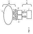
- FIG. 1 schematically illustrated embodiment of a tunable laser includes a first resonator 1, which contains an optical amplifying medium 4. Furthermore, the laser contains a second resonator 2, which is preferably a passive resonator, that is to say a resonator without an optical amplification medium. Between the first resonator 1 and the second resonator 2, a wavelength-selective optical filter 3 is arranged, which is tuned periodically and thus each to a specific Time is transparent for a certain wavelength range and allows for these wavelengths the transition from the first resonator into the second resonator, as indicated by the arrows 5.
- a wavelength-selective optical filter 3 is arranged, which is tuned periodically and thus each to a specific Time is transparent for a certain wavelength range and allows for these wavelengths the transition from the first resonator into the second resonator, as indicated by the arrows 5.
- the second resonator acts as an optical memory 6, in which the light circulates until the filter 3 is again tuned after a number of cycles in such a way that it is transparent for the specific wavelength.
- the light needs time T. for one complete revolution.
- the second resonator 2 In contrast to an optical delay path known from conventional FDML lasers, the second resonator 2 thus passes through several times, the number of rounds n being limited only by the optical losses occurring in the case of very many circulations.
- the first resonator 1, which contains the optically active medium 4 should be so short that the light during the time during which the optical filter 3 for a certain wavelength is transparent, can complete a full round in the first resonator. After a circulation in the first resonator, which is short in relation to the second resonator, the filter is therefore slightly or not detuned. It is possible that the light will be transmitted in two slightly different states of the filter if the filter is not phased out becomes. Thus, in this configuration, there is no perfect synchronization between the round trip time in the first resonator and the period t at which the filter 3 is tuned.
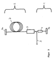
- FIG. 2 schematically shows an embodiment of a laser according to the invention, in which the coupling and decoupling of light from the first resonator 1 in the second resonator 2 and vice versa not by a single filter, but by two filters 3a, 3b is effected.
- light from the second resonator 2 acting as an optical memory 6 can be coupled through a first filter 3a into the first resonator 1, which contains the optical amplifier 4. After circulating through the first resonator 1, the light is coupled back into the second resonator 2 through the second filter 3b.
- the second filter 3b is tuned after a circulation time of the light by the first resonator 1 to the wavelength previously transmitted by the first filter 3a. In this way, a perfect synchronization can be achieved as with an FDML laser.
- the first resonator 1 is traversed by the light only once, in contrast to conventional laser resonators.
- the second resonator 2 includes an optical fiber 7.
- the fiber 7 is preferably a single-mode fiber.
- the fiber 7 may be a polarization-maintaining fiber to prevent a change in polarization state and to avoid instabilities.
- additional polarization controllers can also be used to produce a desired one Adjust polarization.
- the second resonator 2 is bounded on one side by a first mirror 8a, which may be, for example, a fiber Bragg grating, a metal mirror or a dielectric mirror, a Sagnac-type fiber mirror or a Faraday mirror ,
- a first mirror 8a which may be, for example, a fiber Bragg grating, a metal mirror or a dielectric mirror, a Sagnac-type fiber mirror or a Faraday mirror
- the second resonator 2 is limited by a tunable fiber Fabry-Perot (FFP-TF) filter 3 or an acousto-optically tunable fiber Bragg grating filter.
- FFP-TF tunable fiber Fabry-Perot
- a plano-concave type is preferably used, with the flat side facing the fiber 7. In this way, the intensity reflected back into the fiber is increased. With an orientation of the concave surface in the direction of the fiber 7 otherwise losses would occur.
- a filter is used in which the non-transmitted light is completely reflected back into the second resonator.
- the filter is preferably operated with a substantially periodic electronic waveform with low phase and amplitude noise (typically less than 80 dB).
- feedback loops can be used to stabilize the frequency with respect to the resonator length and thus compensate for thermally induced fluctuations.
- the first resonator 1 is limited by the tunable filter 3 and another mirror 8b.
- the optical amplifier 4 included in the first resonator may be, for example, a semiconductor optical amplifier (SOA).
- SOA semiconductor optical amplifier
- rare earth doped fiber amplifiers or nonlinear gain media.
- the frequency with which the optical filter 3 is modulated corresponds to a sub-harmonic of the rotational frequency in the second resonator 2.
- the possible tuning frequencies of the optical filter 3 at an optical path length of 300 m in the second resonator 2 are 500 KHz, 250 KHz, 166.66 KHz, 125 KHz, etc. but also 1 MHz, 1.5 MHz, etc.
- the light is coupled from the second resonator 2 after n round trips from the second resonator into the first resonator, amplified in the first resonator, and again coupled into the second resonator 2. After another n rounds, the light is again transmitted by the filter 3 and amplified again.
- the filter 3 preferably has a high transmission, preferably of more than 50%, and thus a low back reflection.
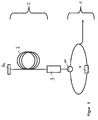
- FIG. 4 shows a modification of the in FIG. 3 illustrated embodiment in which within the first resonator 1, an optical coupler 10 is arranged, is coupled by the part of the laser radiation from the first resonator 1, as indicated by the arrow 9.
- the first resonator 1 includes an optical circulator 11.
- the circulator 11 serves as an optical switch, via which the annular part of the first resonator 1 is connected to the filter 3.
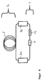
- FIG. 6 1 schematically shows an exemplary embodiment of a tunable laser, in which the second resonator 2 has at each end a filter 3a, 3b, in particular a Fabry-Perot filter, via which the second resonator 2 is coupled to the first resonator 1.
- the filters 3a, 3b can be synchronized such that they each have a transmission maximum after one revolution through the first resonator.
- This embodiment has the advantage that a time-shifted double passage of the light during coupling and decoupling from the first resonator is avoided.
- the first resonator includes an optical isolator 12 which is transparent only in the direction indicated by the arrow.
- a further insulator may be provided in the first resonator, wherein the insulators are preferably arranged on both sides of the optical amplification medium 4.
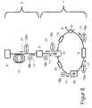
- FIG. 7 shows a bidirectional embodiment for improved polarization stabilization.
- the second resonator 2 includes a polarization controller 13.
- the first resonator 1 designed as a ring resonator and with a polarization-maintaining fiber 7a, also called a polarization maintaining fiber, comprises a polarization-dependent amplifying amplifier medium 4.
- the amplifier medium 4 may be, for example, an optical semiconductor amplifier, also referred to as a semiconductor optical amplifier or SOA.
- the amplifier medium 4 is designed such that it only amplifies light of a polarization direction, in accordance with the exemplary embodiment FIG. 8 For example, if this is light, it is horizontal with respect to the plane of the drawing Polarization direction 18a, symbolized by double arrows. Light with direction of polarization perpendicular to the plane 18b is symbolized by dots. The running direction of the light is indicated by arrows 17.
- An optical circulator 11 is located between the annular first resonator 1 and the filter 3 configured as a fiber Fabry-Perot.
- the circulator 11 in this case conducts light from connection A to connection B. Light entering the connection B exits from the connection C. off, and light entering port C will not be forwarded.
- the circulator 11 thus acts for light from the direction of the terminal C as an optical isolator. On the polarization direction of the light of the circulator 11 has no significant influence.
- the first resonator 1 Between terminal C of the circulator 11 and optical amplifier medium 4 is a 90 ° splice 16, which connects two ends of the polarization-maintaining fiber 7a with each other so that the ends are rotated by 90 ° to each other. That is, when passing through the 90 ° splice 16, the polarization direction 18a, 18b of the light is rotated 90 ° with respect to the plane of the drawing.
- the first resonator 1 further comprises an optical coupler 10.
- a polarization maintaining fiber 7b is also attached, the second end of which is connected to the filter 3.
- a first, the circulator 11 facing side of the filter 3 has a lower reflectivity than a second side of the filter 3, which faces the second resonator 2.
- the reflectivity of the first side is preferably less than 60%, more preferably less than 50%.
- the reflectivity of the second side is preferably more than 90%, particularly preferably more than 95%.
- the passive second resonator 2 is thus bounded on the one hand by the highly reflective second side of the filter 3, on the other hand by a mirror 8 designed as a Faraday mirror.
- the mirror 8 rotates the polarization direction 18a, 18b of the reflected light by 90 ° in comparison to the incident light.
- Filter 3 and mirror 8 are connected to each other via a fiber 7c.
- This fiber is configured as a single-mode fiber or as a polarization-maintaining fiber.
- the effect occurs that light with frequencies at the edge of the amplification range of the amplifier medium 4 is amplified only comparatively poorly compared to frequencies in the center of the amplification range. That is, if both light with frequencies in the center, and light with frequencies at the edge of the gain range in a laser resonator, so is almost exclusively the light amplified with frequencies in the center. This effect can lead to a reduced frequency bandwidth of a laser.
- the laser can, as in FIG. 8 represented, be constructed.
- the mode of operation is explained in more detail below. Since the amplifier amplifies 4 polarization selective, the light generated by the amplifier 4 know a certain direction of polarization 18 a, for example parallel to the plane of the drawing. This generated light passes to the circulator 11 and is passed from port A to port B and then passes to the filter 3.
- the tunable filter 3 is transmissive to the wavelength of the light at the time the light impinges. or (B) the filter 3 is blocking for the light, that is, a part of the light is lost, another part is reflected back towards the terminal B of the circulator 11 and passes through terminal C back into the ring-like part of the first resonator first
- the light is in the second resonator 2 until the filter 3 is again transmissive for the corresponding wavelength and the light is coupled into the first resonator 1.
- the light in the second resonator 2 runs in the direction of the mirror 8, it has, for example, a polarization direction 18a parallel to the plane of the drawing. If the light then hits the Faraday mirror 8, the light is reflected and its polarization direction is rotated by 90 ° so that the polarization direction 18b is then perpendicular to the plane of the drawing. Since the filter 3 has no polarization effect, the light is reflected with the polarization direction unchanged and runs back in the direction of the mirror 8, which again rotates the polarization direction by 90 ° in the case of reflection.
- the filter 3 is to be tuned with a period t such that the light is coupled into the first resonator 1 after an odd number of cycles in the second resonator 2, for example after 15 cycles.
- this light has a polarization direction 18b rotated by 90 ° with respect to the light emerging from the first resonator 1.
- This coupled light is passed from port B to port C of circulator 11 and passes to the 90 ° splice 16, again rotating the polarization direction 18b of the light by 90 °. After passing through the 90 ° -Sp dealtes 16, the polarization direction 18a of the light is thus again parallel to the plane. So the light reaches with the appropriate polarization direction 18a the amplifier medium 4, so that it is amplified by this.
- the filter 3 acts to block the light generated by the amplifier medium 4, that is, the filter 3 reflects the light back in the direction of the circulator 11 while maintaining its polarization direction 18a. That is, the light is in the embodiment according to FIG. 8 then polarized parallel to the plane of the drawing. From the circulator 11, the light is forwarded to the 90 ° splice 16 and the polarization of the light is rotated via this in a direction 18b perpendicular to the plane, whereupon this light from the amplifier medium 4 can not be amplified. Thus, only light can be amplified by the amplifier medium 4, which has completely passed through the second resonator 2 at least once. Thus, only with the tuning period t of the filter 3 synchronous wavelengths of light can be amplified, the gain of other wavelengths is suppressed. There is no significant narrowing of the gain bandwidth.
- the first resonator 1 passes through twice and thus twice through the 90 ° splice 16 undergoes a polarization rotation and thereby again has a polarization direction 18 a, which would be amplified by the amplifier medium 4 is also reflected twice from the filter 3. Since the filter 3 in blocking position in the direction of the circulator 11 has only a relatively low reflectivity, this light is also effectively suppressed and prevented amplification of this light.
- the first resonator 1 has optical isolators 12 which can be based on the Faraday effect and only light let pass in a running direction 17.
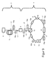
- the amplifier medium 4 may alternatively be designed as a non-polarization-dependent amplifying medium, but in this case is to be combined with a polarizer.
- a polarization-dependent reflecting beam splitter 15 also referred to as a polarizing beam splitter, short PBS, used.
- Light having, for example, a polarization direction 18a parallel to the plane of the drawing and reaching the beam splitter 15 is reflected in the direction of the filter 3.
- Light, for which the filter 3 is blocking, is reflected by the filter 3 back in the direction of the beam splitter 20, wherein the polarization direction 18a is maintained.
- Such light is then reflected back to the amplifier medium 4 by the beam splitter 20 on the same path as the incoming light and blocked by the optical isolator 12a.
- the polarization-dependent reflecting beam splitter 15 and the optical isolator 12a By the combination of the polarization-dependent reflecting beam splitter 15 and the optical isolator 12a, light of asynchronous wavelength at the period t of the filter 3 can be effectively suppressed even if the first side of the filter 3 should have high reflectivity for such light.
- a second isolator 12b may additionally be placed in the first resonator 1.
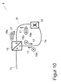
- FIG. 10 schematically a Sagnac-type fiber mirror is shown.
- a Sagnac-type fiber mirror may be used as a polarization-rotating mirror 8 as an alternative to a Faraday mirror.
- Light from the fiber 7c which is designed as a single-mode fiber or polarization-maintaining fiber, passes to a terminal A of a polarization-dependent reflective beam splitter 15.
- Light having a polarization direction 18a parallel to the plane is transmitted by the beam splitter 15 in the direction of port B, light having a polarization direction 18b perpendicular to the drawing plane is reflected in the direction of port C.
- the terminals B and C of the beam splitter 15 are connected to each other via polarization maintaining fibers 7e, 7f, wherein the fibers 7e, 7f are connected to each other via a 90 ° splice 16.
- the polarization direction 18a of the light which comes from terminal B of the beam splitter 15 and runs in the direction of connection C, is rotated by 90 °. Since the direction of polarization 18b is then perpendicular to the plane of the drawing, the light is reflected by the beam splitter 15 via connection A back into the fiber 7c. The same applies to light that runs from terminal C of the beam splitter 15 to terminal B.
- the polarization direction of the light passing through the arrangement can be rotated by 90 °.
- the difference in the lengths of the fibers 7e, 7f is preferably shorter than the so-called beat length, particularly preferably shorter than half the beat length.
- the difference in length between the fibers 7e, 7f is in particular less than 4 mm.
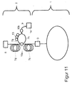
- FIG. 11 is schematically shown an embodiment in which the radiation 9 is coupled out in the second resonator 2.
- the first resonator is according to, for example FIG. 9 or FIG. 10 designed.
- an optical coupler 10a is attached, via which light is coupled out of the second resonator 2.
- the fibers 7c, 7d preferably have a similar length, more preferably they are the same length.
- two fibers 7g, 7h are attached.
- Light traveling in the second resonator 2 from the filter 3 in the direction of the mirror 8 is coupled into the fiber 7g and light, which in the second resonator 2 passes from the mirror 8 in the direction of the filter 3, into the fiber 7h.
- the polarization direction of the light in the fiber 7g can be adjusted so that the polarization direction corresponds to that of the light in the fiber 7h.
- the light from both fibers 7g, 7h can be combined.
- a polarization-dependent reflecting beam splitter in an arrangement analogous to that in FIG. 10 are used to combine the two partial beams of the fibers 7g, 7h together.
- the polarization controller 13 is not necessary.
- the outcoupled radiation 9 may have different polarization directions at different times, which may be desirable in some applications.
- a further alternative is to use a polarization-independent 50% beam splitter instead of polarization controller 13 and / or polarization-dependent beam splitter or coupler 10b.
- polarization controller 13 instead of polarization controller 13 and / or polarization-dependent beam splitter or coupler 10b.
- the coupling losses when merging the partial beams of the fibers 7g and 7h, however, are relatively high.
- the thus coupled-out radiation 9 can then optionally either be guided to a measuring station as required or further amplified by means of an active amplifier fiber or an optical semiconductor amplifier 14.
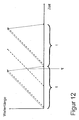
- FIG. 12 Another problem that can occur with a sub-harmonic FDML laser is in FIG. 12 illustrated.
- the transmission wavelength of the filter 3 or the wavelength of the light striking the filter 3 is plotted against time.
- the transmission wavelength of the filter 3 is shown as a solid line, the wavelength of the light incident on the filter 3 as a dashed line.
- the filter 3 is operated for example with a sawtooth voltage.
- the two edges of the sawtooth voltage preferably have a different pitch, so that the return of the filter 3 to a start position is faster than the tuning of the transmission wavelength.
- the filter 3 is driven back, it may happen that it has a transmission wavelength at which light is then transmitted through the filter 3 into the first resonator 1 during the retraction. In FIG. 12 this happens at the time ⁇ . This can lead to unwanted power fluctuations of the FDML laser.
- This effect can be avoided, for example, by suitably adapting the length of the second resonator 2 and the tuning period t of the filter 3 to one another.
- FIG. 13 shown schematically.
- the part of the fiber 7c belonging to the second resonator 2, with which the second side of the filter 3 is formed, is mechanically fixed.
- the first side of the filter 3, which is in communication with the fiber 7b, is movably supported.
- a longitudinal movement 19a in the beam direction which is responsible for the frequency tuning of the fiber Fabry-Perot filter 3 there is additionally a movement 19b with a component perpendicular to the transmission direction of the filter 3.
- the filter 3 or the end of the fiber 7b is temporarily shifted in this way in that the quality of the Fabry-Perot is reduced and no light can pass from the fiber 7b into the fiber 7c or vice versa.
- Such a two- or even three-dimensional movement of the first side of the filter 3 or the fiber 7b can be realized for example via a piezo drive.
Claims (15)
- Laser accordable, comportant un milieu d'amplification (4) optique, un premier résonateur (1) contenant le milieu d'amplification (4) optique et au moins un filtre optique (3) accordable périodiquement, caractérisé en ce que- le laser contient un deuxième résonateur (2), dans lequel la lumière issue du premier résonateur (1) d'une longueur d'onde du laser présente une période T,- le filtre optique (3) est disposé entre le premier résonateur (1) et le deuxième résonateur (2) et le laser accordable est conçu de telle sorte que le filtre optique (3) est réglé avec une période t, et- pour la période t, on applique la formule :
 - et le laser accordable est conçu de telle sorte que pendant la période t, le deuxième résonateur (2) est traversé à plusieurs reprises par la lumière ayant la longueur d'onde du laser.
 - Laser accordable selon la revendication 1, caractérisé en ce que n ≥ 2.
- Laser accordable selon la revendication 1 ou 2, caractérisé en ce que le premier résonateur (1) et le deuxième résonateur (2) sont délimités chacun sur au moins un côté par le filtre optique (3).
- Laser accordable selon la revendication 3, caractérisé en ce que le laser accordable est conçu de telle sorte que le premier résonateur (1) est traversé pendant la période t une fois seulement par la lumière ayant la longueur d'onde du laser.
- Laser accordable selon l'une quelconque des revendications précédentes, caractérisé en ce que le deuxième résonateur (2) est un résonateur passif.
- Laser accordable selon l'une quelconque des revendications précédentes, caractérisé en ce que le deuxième résonateur (2) contient au moins une fibre optique (7).
- Laser accordable selon l'une quelconque des revendications précédentes, caractérisé en ce que le filtre optique (3) est un filtre à fibres de Fabry-Perot accordable.
- Laser accordable selon l'une quelconque des revendications précédentes, caractérisé en ce que le filtre optique (3) peut être fermé par intermittence pendant une période t, indépendamment de la fréquence.
- Laser accordable selon la revendication 8, caractérisé en ce que le filtre optique (3) peut être orienté perpendiculairement à une direction de transmission.
- Laser accordable selon l'une quelconque des revendications précédentes, caractérisé en ce que le deuxième résonateur (2) comporte au moins un élément agissant par rotation de la polarisation.
- Laser accordable selon la revendication 10, caractérisé en ce qu'au moins un élément agissant par rotation de la polarisation est un miroir de Faraday ou un miroir à fibres du type Sagnac.
- Laser accordable selon l'une quelconque des revendications précédentes, caractérisé en ce que le premier résonateur (1) comporte au moins un milieu d'amplification (4) sélectif de polarisation.
- Laser accordable selon l'une quelconque des revendications précédentes, caractérisé en ce que le rayonnement issu du deuxième résonateur (2) est déclenchable.
- Laser accordable selon l'une quelconque des revendications précédentes, caractérisé en ce que le laser comporte au moins un post-amplificateur (14).
- Laser accordable selon l'une quelconque des revendications précédentes, caractérisé en ce que le premier résonateur (1) comporte au moins une fibre recevant la polarisation.
Applications Claiming Priority (2)
| Application Number | Priority Date | Filing Date | Title |
|---|---|---|---|
| DE102007021313 | 2007-05-07 | ||
| PCT/DE2008/000766 WO2008135034A1 (fr) | 2007-05-07 | 2008-05-05 | Laser accordable |
Publications (2)
| Publication Number | Publication Date |
|---|---|
| EP2147488A1 EP2147488A1 (fr) | 2010-01-27 |
| EP2147488B1 true EP2147488B1 (fr) | 2014-03-26 |
Family
ID=39688804
Family Applications (1)
| Application Number | Title | Priority Date | Filing Date |
|---|---|---|---|
| EP08758025.4A Not-in-force EP2147488B1 (fr) | 2007-05-07 | 2008-05-05 | Laser accordable |
Country Status (4)
| Country | Link |
|---|---|
| US (1) | US8130802B2 (fr) |
| EP (1) | EP2147488B1 (fr) |
| DE (1) | DE112008001852A5 (fr) |
| WO (1) | WO2008135034A1 (fr) |
Families Citing this family (15)
| Publication number | Priority date | Publication date | Assignee | Title |
|---|---|---|---|---|
| DE102008045634A1 (de) | 2008-09-03 | 2010-03-04 | Ludwig-Maximilians-Universität München | Wellenlängenabstimmbare Lichtquelle |
| DE102009048216A1 (de) * | 2009-06-05 | 2010-12-09 | Toptica Photonics Ag | Abstimmbare Lichtquelle |
| US8526472B2 (en) * | 2009-09-03 | 2013-09-03 | Axsun Technologies, Inc. | ASE swept source with self-tracking filter for OCT medical imaging |
| US8670129B2 (en) | 2009-09-03 | 2014-03-11 | Axsun Technologies, Inc. | Filtered ASE swept source for OCT medical imaging |
| DE102009042207A1 (de) | 2009-09-18 | 2011-04-21 | Ludwig-Maximilians-Universität München | Wellenlängenabstimmbare Lichtquelle |
| US8582619B2 (en) | 2011-03-15 | 2013-11-12 | Lightlab Imaging, Inc. | Methods, systems, and devices for timing control in electromagnetic radiation sources |
| US9164240B2 (en) | 2011-03-31 | 2015-10-20 | Lightlab Imaging, Inc. | Optical buffering methods, apparatus, and systems for increasing the repetition rate of tunable light sources |
| US8908189B2 (en) | 2011-04-15 | 2014-12-09 | Carl Zeiss Meditec, Inc. | Systems and methods for swept-source optical coherence tomography |
| US8582109B1 (en) | 2011-08-01 | 2013-11-12 | Lightlab Imaging, Inc. | Swept mode-hopping laser system, methods, and devices for frequency-domain optical coherence tomography |
| WO2013066631A1 (fr) | 2011-10-18 | 2013-05-10 | The General Hospital Corporation | Appareil et procédés de production et/ou d'utilisation de retard(s) optique(s) de recirculation |
| US9784559B2 (en) | 2012-03-21 | 2017-10-10 | Ludwig-Maximilians-Universität München | Swept source OCT system and method with phase-locked detection |
| EP2828612B1 (fr) | 2012-03-21 | 2020-04-22 | Ludwig-Maximilians-Universität München | Procédure de réduction de la dimensionnalité d'un signal enregistré spatialement déduit des propriétés optiques d'un échantillon et dispositif associé |
| US10243328B2 (en) | 2013-11-20 | 2019-03-26 | Elenion Technologies, Llc | Semiconductor laser |
| US9450379B2 (en) * | 2013-11-20 | 2016-09-20 | Coriant Advanced Technology, LLC | Quantum dot SOA-silicon external cavity multi-wavelength laser |
| CN105917533A (zh) * | 2013-11-20 | 2016-08-31 | 科锐安先进科技有限公司 | 硅光子平台上基于萨格纳克环形镜的激光腔 |
Family Cites Families (8)
| Publication number | Priority date | Publication date | Assignee | Title |
|---|---|---|---|---|
| DE69212927T2 (de) * | 1991-07-22 | 1997-02-27 | Hewlett Packard Co | Kontinuierlich abgestimmbarer optischer Resonator |
| US5513196A (en) * | 1995-02-14 | 1996-04-30 | Deacon Research | Optical source with mode reshaping |
| GB9618764D0 (en) * | 1996-09-09 | 1996-10-23 | Univ Southampton | Wavelength-swept fiber laser with frequency shifted feedback |
| US6052393A (en) * | 1996-12-23 | 2000-04-18 | The Regents Of The University Of Michigan | Broadband Sagnac Raman amplifiers and cascade lasers |
| US6529328B1 (en) * | 1998-08-07 | 2003-03-04 | Jds Fitel Inc. | Optical filter |
| SE0201413D0 (sv) * | 2002-05-10 | 2002-05-10 | Proximion Fiber Optics Ab | Scanning light source |
| US7157712B2 (en) * | 2004-09-29 | 2007-01-02 | Axsun Technologies, Inc. | Method and system for noise control in semiconductor spectroscopy system |
| WO2006079078A2 (fr) | 2005-01-20 | 2006-07-27 | Massachusetts Institute Of Technology | Procedes et appareil de verrouillage de mode |
-
2008
- 2008-05-05 WO PCT/DE2008/000766 patent/WO2008135034A1/fr active Application Filing
- 2008-05-05 DE DE112008001852T patent/DE112008001852A5/de not_active Withdrawn
- 2008-05-05 EP EP08758025.4A patent/EP2147488B1/fr not_active Not-in-force
-
2009
- 2009-11-04 US US12/612,472 patent/US8130802B2/en not_active Expired - Fee Related
Also Published As
| Publication number | Publication date |
|---|---|
| WO2008135034A1 (fr) | 2008-11-13 |
| US8130802B2 (en) | 2012-03-06 |
| DE112008001852A5 (de) | 2010-04-22 |
| US20100103964A1 (en) | 2010-04-29 |
| EP2147488A1 (fr) | 2010-01-27 |
Similar Documents
| Publication | Publication Date | Title |
|---|---|---|
| EP2147488B1 (fr) | Laser accordable | |
| EP2364106B1 (fr) | Source lumineuse réglable en longueur d'onde | |
| DE69935648T2 (de) | Wellenlängenvariabler laser und verfahren zu seinem betrieb | |
| DE112004002187B4 (de) | Gepulste Laserquellen | |
| DE112014005158B4 (de) | Kompakte faserbasierte Kurzpuls-Laserquellen | |
| DE19642925B4 (de) | Verfahren und Vorrichtung zur Erzeugung ultrakurzer Impulse mit einstellbaren Repetitionsraten von passiv modenverkoppelten Faserlasern | |
| DE4445244B4 (de) | Gegenüber Umwelteinflüssen stabile passiv moden-verkoppelte Faserlaser-Impulsquelle | |
| EP3046191B1 (fr) | Laser a fibres a impulsions ultracourtes | |
| DE102006023601B4 (de) | Lasersystem | |
| DE112005000710T5 (de) | Modulares faserbasiertes Chirped-Puls-Verstärkersystem | |
| DE112011103954T5 (de) | Frequenzkamm-Quelle mit großem Abstand der Kammlinien | |
| DE19512160A1 (de) | Verfahren und Gerät zur Erzeugung ultrakurzer Impulse mit hoher Energie | |
| DE19510432A1 (de) | Verfahren und Gerät zur Steuerung der Laser-Emissionswellenlänge unter Ausnutzung nichtlinearer Effekte | |
| DE102012002470A1 (de) | CO2-Laser mit schneller Leistungssteuerung | |
| EP3041093B1 (fr) | Système de résonateur optique et procédé de réglage d'un temps de cycle dans un résonateur | |
| EP4264754A1 (fr) | Oscillateur à fibre à verrouillage de mode passif, et dispositif laser comprenant un oscillateur à fibre de ce type | |
| WO2009068312A2 (fr) | Laser à fibres doté d'un résonateur annulaire | |
| DE10052461B4 (de) | Vorrichtung zum Erzeugen von Laserlicht | |
| AT506600B1 (de) | Anordnung zur optischen verstärkung von lichtpulsen | |
| DE102016102781B4 (de) | Erzeugung von zwei synchronisierten Laserimpulszügen | |
| DE4101521C2 (de) | Verfahren zur Wellenlängenselektion bei Einfrequenz-Mikrokristall-Lasern | |
| EP1775806B1 (fr) | Procedé pour la production d'impulsions temporelles rectangulaires ultracourtes | |
| DE10009380B4 (de) | Faserverstärker | |
| WO2004068657A1 (fr) | Amplificateur a recuperation a compensation de dispersion interne au resonateur et impulsion seed sans dispersion positive | |
| WO2004068651A2 (fr) | Systeme laser |
Legal Events
| Date | Code | Title | Description |
|---|---|---|---|
| PUAI | Public reference made under article 153(3) epc to a published international application that has entered the european phase |
Free format text: ORIGINAL CODE: 0009012 |
|
| 17P | Request for examination filed |
Effective date: 20091109 |
|
| AK | Designated contracting states |
Kind code of ref document: A1 Designated state(s): AT BE BG CH CY CZ DE DK EE ES FI FR GB GR HR HU IE IS IT LI LT LU LV MC MT NL NO PL PT RO SE SI SK TR |
|
| AX | Request for extension of the european patent |
Extension state: AL BA MK RS |
|
| 17Q | First examination report despatched |
Effective date: 20100709 |
|
| DAX | Request for extension of the european patent (deleted) | ||
| REG | Reference to a national code |
Ref country code: DE Ref legal event code: R079 Ref document number: 502008011499 Country of ref document: DE Free format text: PREVIOUS MAIN CLASS: H01S0003100000 Ipc: H01S0003067000 |
|
| GRAP | Despatch of communication of intention to grant a patent |
Free format text: ORIGINAL CODE: EPIDOSNIGR1 |
|
| RIC1 | Information provided on ipc code assigned before grant |
Ipc: H01S 3/08 20060101ALN20130906BHEP Ipc: H01S 3/106 20060101ALN20130906BHEP Ipc: H01S 3/067 20060101AFI20130906BHEP |
|
| INTG | Intention to grant announced |
Effective date: 20131009 |
|
| GRAS | Grant fee paid |
Free format text: ORIGINAL CODE: EPIDOSNIGR3 |
|
| GRAA | (expected) grant |
Free format text: ORIGINAL CODE: 0009210 |
|
| AK | Designated contracting states |
Kind code of ref document: B1 Designated state(s): AT BE BG CH CY CZ DE DK EE ES FI FR GB GR HR HU IE IS IT LI LT LU LV MC MT NL NO PL PT RO SE SI SK TR |
|
| REG | Reference to a national code |
Ref country code: GB Ref legal event code: FG4D Free format text: NOT ENGLISH |
|
| REG | Reference to a national code |
Ref country code: CH Ref legal event code: EP |
|
| REG | Reference to a national code |
Ref country code: AT Ref legal event code: REF Ref document number: 659406 Country of ref document: AT Kind code of ref document: T Effective date: 20140415 |
|
| REG | Reference to a national code |
Ref country code: DE Ref legal event code: R096 Ref document number: 502008011499 Country of ref document: DE Effective date: 20140430 |
|
| REG | Reference to a national code |
Ref country code: IE Ref legal event code: FG4D Free format text: LANGUAGE OF EP DOCUMENT: GERMAN |
|
| PG25 | Lapsed in a contracting state [announced via postgrant information from national office to epo] |
Ref country code: NO Free format text: LAPSE BECAUSE OF FAILURE TO SUBMIT A TRANSLATION OF THE DESCRIPTION OR TO PAY THE FEE WITHIN THE PRESCRIBED TIME-LIMIT Effective date: 20140626 Ref country code: LT Free format text: LAPSE BECAUSE OF FAILURE TO SUBMIT A TRANSLATION OF THE DESCRIPTION OR TO PAY THE FEE WITHIN THE PRESCRIBED TIME-LIMIT Effective date: 20140326 |
|
| REG | Reference to a national code |
Ref country code: NL Ref legal event code: VDEP Effective date: 20140326 |
|
| REG | Reference to a national code |
Ref country code: LT Ref legal event code: MG4D |
|
| PG25 | Lapsed in a contracting state [announced via postgrant information from national office to epo] |
Ref country code: FI Free format text: LAPSE BECAUSE OF FAILURE TO SUBMIT A TRANSLATION OF THE DESCRIPTION OR TO PAY THE FEE WITHIN THE PRESCRIBED TIME-LIMIT Effective date: 20140326 Ref country code: SE Free format text: LAPSE BECAUSE OF FAILURE TO SUBMIT A TRANSLATION OF THE DESCRIPTION OR TO PAY THE FEE WITHIN THE PRESCRIBED TIME-LIMIT Effective date: 20140326 |
|
| PG25 | Lapsed in a contracting state [announced via postgrant information from national office to epo] |
Ref country code: LV Free format text: LAPSE BECAUSE OF FAILURE TO SUBMIT A TRANSLATION OF THE DESCRIPTION OR TO PAY THE FEE WITHIN THE PRESCRIBED TIME-LIMIT Effective date: 20140326 Ref country code: HR Free format text: LAPSE BECAUSE OF FAILURE TO SUBMIT A TRANSLATION OF THE DESCRIPTION OR TO PAY THE FEE WITHIN THE PRESCRIBED TIME-LIMIT Effective date: 20140326 |
|
| PG25 | Lapsed in a contracting state [announced via postgrant information from national office to epo] |
Ref country code: RO Free format text: LAPSE BECAUSE OF FAILURE TO SUBMIT A TRANSLATION OF THE DESCRIPTION OR TO PAY THE FEE WITHIN THE PRESCRIBED TIME-LIMIT Effective date: 20140326 Ref country code: NL Free format text: LAPSE BECAUSE OF FAILURE TO SUBMIT A TRANSLATION OF THE DESCRIPTION OR TO PAY THE FEE WITHIN THE PRESCRIBED TIME-LIMIT Effective date: 20140326 Ref country code: EE Free format text: LAPSE BECAUSE OF FAILURE TO SUBMIT A TRANSLATION OF THE DESCRIPTION OR TO PAY THE FEE WITHIN THE PRESCRIBED TIME-LIMIT Effective date: 20140326 Ref country code: BG Free format text: LAPSE BECAUSE OF FAILURE TO SUBMIT A TRANSLATION OF THE DESCRIPTION OR TO PAY THE FEE WITHIN THE PRESCRIBED TIME-LIMIT Effective date: 20140626 Ref country code: CZ Free format text: LAPSE BECAUSE OF FAILURE TO SUBMIT A TRANSLATION OF THE DESCRIPTION OR TO PAY THE FEE WITHIN THE PRESCRIBED TIME-LIMIT Effective date: 20140326 Ref country code: CY Free format text: LAPSE BECAUSE OF FAILURE TO SUBMIT A TRANSLATION OF THE DESCRIPTION OR TO PAY THE FEE WITHIN THE PRESCRIBED TIME-LIMIT Effective date: 20140326 Ref country code: IS Free format text: LAPSE BECAUSE OF FAILURE TO SUBMIT A TRANSLATION OF THE DESCRIPTION OR TO PAY THE FEE WITHIN THE PRESCRIBED TIME-LIMIT Effective date: 20140726 |
|
| PG25 | Lapsed in a contracting state [announced via postgrant information from national office to epo] |
Ref country code: PL Free format text: LAPSE BECAUSE OF FAILURE TO SUBMIT A TRANSLATION OF THE DESCRIPTION OR TO PAY THE FEE WITHIN THE PRESCRIBED TIME-LIMIT Effective date: 20140326 Ref country code: ES Free format text: LAPSE BECAUSE OF FAILURE TO SUBMIT A TRANSLATION OF THE DESCRIPTION OR TO PAY THE FEE WITHIN THE PRESCRIBED TIME-LIMIT Effective date: 20140326 Ref country code: SK Free format text: LAPSE BECAUSE OF FAILURE TO SUBMIT A TRANSLATION OF THE DESCRIPTION OR TO PAY THE FEE WITHIN THE PRESCRIBED TIME-LIMIT Effective date: 20140326 |
|
| PG25 | Lapsed in a contracting state [announced via postgrant information from national office to epo] |
Ref country code: PT Free format text: LAPSE BECAUSE OF FAILURE TO SUBMIT A TRANSLATION OF THE DESCRIPTION OR TO PAY THE FEE WITHIN THE PRESCRIBED TIME-LIMIT Effective date: 20140728 Ref country code: LU Free format text: LAPSE BECAUSE OF FAILURE TO SUBMIT A TRANSLATION OF THE DESCRIPTION OR TO PAY THE FEE WITHIN THE PRESCRIBED TIME-LIMIT Effective date: 20140505 |
|
| REG | Reference to a national code |
Ref country code: CH Ref legal event code: PL |
|
| REG | Reference to a national code |
Ref country code: DE Ref legal event code: R097 Ref document number: 502008011499 Country of ref document: DE |
|
| PG25 | Lapsed in a contracting state [announced via postgrant information from national office to epo] |
Ref country code: MC Free format text: LAPSE BECAUSE OF FAILURE TO SUBMIT A TRANSLATION OF THE DESCRIPTION OR TO PAY THE FEE WITHIN THE PRESCRIBED TIME-LIMIT Effective date: 20140326 Ref country code: LI Free format text: LAPSE BECAUSE OF NON-PAYMENT OF DUE FEES Effective date: 20140531 Ref country code: CH Free format text: LAPSE BECAUSE OF NON-PAYMENT OF DUE FEES Effective date: 20140531 Ref country code: DK Free format text: LAPSE BECAUSE OF FAILURE TO SUBMIT A TRANSLATION OF THE DESCRIPTION OR TO PAY THE FEE WITHIN THE PRESCRIBED TIME-LIMIT Effective date: 20140326 |
|
| PLBE | No opposition filed within time limit |
Free format text: ORIGINAL CODE: 0009261 |
|
| STAA | Information on the status of an ep patent application or granted ep patent |
Free format text: STATUS: NO OPPOSITION FILED WITHIN TIME LIMIT |
|
| REG | Reference to a national code |
Ref country code: IE Ref legal event code: MM4A |
|
| 26N | No opposition filed |
Effective date: 20150106 |
|
| PG25 | Lapsed in a contracting state [announced via postgrant information from national office to epo] |
Ref country code: IT Free format text: LAPSE BECAUSE OF FAILURE TO SUBMIT A TRANSLATION OF THE DESCRIPTION OR TO PAY THE FEE WITHIN THE PRESCRIBED TIME-LIMIT Effective date: 20140326 |
|
| REG | Reference to a national code |
Ref country code: DE Ref legal event code: R097 Ref document number: 502008011499 Country of ref document: DE Effective date: 20150106 |
|
| PG25 | Lapsed in a contracting state [announced via postgrant information from national office to epo] |
Ref country code: IE Free format text: LAPSE BECAUSE OF NON-PAYMENT OF DUE FEES Effective date: 20140505 |
|
| REG | Reference to a national code |
Ref country code: AT Ref legal event code: MM01 Ref document number: 659406 Country of ref document: AT Kind code of ref document: T Effective date: 20140505 |
|
| PG25 | Lapsed in a contracting state [announced via postgrant information from national office to epo] |
Ref country code: SI Free format text: LAPSE BECAUSE OF FAILURE TO SUBMIT A TRANSLATION OF THE DESCRIPTION OR TO PAY THE FEE WITHIN THE PRESCRIBED TIME-LIMIT Effective date: 20140326 |
|
| PG25 | Lapsed in a contracting state [announced via postgrant information from national office to epo] |
Ref country code: AT Free format text: LAPSE BECAUSE OF NON-PAYMENT OF DUE FEES Effective date: 20140505 |
|
| PG25 | Lapsed in a contracting state [announced via postgrant information from national office to epo] |
Ref country code: MT Free format text: LAPSE BECAUSE OF FAILURE TO SUBMIT A TRANSLATION OF THE DESCRIPTION OR TO PAY THE FEE WITHIN THE PRESCRIBED TIME-LIMIT Effective date: 20140326 |
|
| REG | Reference to a national code |
Ref country code: FR Ref legal event code: PLFP Year of fee payment: 9 |
|
| PG25 | Lapsed in a contracting state [announced via postgrant information from national office to epo] |
Ref country code: GR Free format text: LAPSE BECAUSE OF FAILURE TO SUBMIT A TRANSLATION OF THE DESCRIPTION OR TO PAY THE FEE WITHIN THE PRESCRIBED TIME-LIMIT Effective date: 20140627 |
|
| PG25 | Lapsed in a contracting state [announced via postgrant information from national office to epo] |
Ref country code: HU Free format text: LAPSE BECAUSE OF FAILURE TO SUBMIT A TRANSLATION OF THE DESCRIPTION OR TO PAY THE FEE WITHIN THE PRESCRIBED TIME-LIMIT; INVALID AB INITIO Effective date: 20080505 Ref country code: TR Free format text: LAPSE BECAUSE OF FAILURE TO SUBMIT A TRANSLATION OF THE DESCRIPTION OR TO PAY THE FEE WITHIN THE PRESCRIBED TIME-LIMIT Effective date: 20140326 Ref country code: BE Free format text: LAPSE BECAUSE OF FAILURE TO SUBMIT A TRANSLATION OF THE DESCRIPTION OR TO PAY THE FEE WITHIN THE PRESCRIBED TIME-LIMIT Effective date: 20140531 |
|
| REG | Reference to a national code |
Ref country code: FR Ref legal event code: PLFP Year of fee payment: 10 |
|
| REG | Reference to a national code |
Ref country code: FR Ref legal event code: PLFP Year of fee payment: 11 |
|
| PGFP | Annual fee paid to national office [announced via postgrant information from national office to epo] |
Ref country code: DE Payment date: 20190515 Year of fee payment: 12 |
|
| PGFP | Annual fee paid to national office [announced via postgrant information from national office to epo] |
Ref country code: FR Payment date: 20190521 Year of fee payment: 12 |
|
| PGFP | Annual fee paid to national office [announced via postgrant information from national office to epo] |
Ref country code: GB Payment date: 20190523 Year of fee payment: 12 |
|
| REG | Reference to a national code |
Ref country code: DE Ref legal event code: R119 Ref document number: 502008011499 Country of ref document: DE |
|
| GBPC | Gb: european patent ceased through non-payment of renewal fee |
Effective date: 20200505 |
|
| PG25 | Lapsed in a contracting state [announced via postgrant information from national office to epo] |
Ref country code: GB Free format text: LAPSE BECAUSE OF NON-PAYMENT OF DUE FEES Effective date: 20200505 Ref country code: FR Free format text: LAPSE BECAUSE OF NON-PAYMENT OF DUE FEES Effective date: 20200531 |
|
| PG25 | Lapsed in a contracting state [announced via postgrant information from national office to epo] |
Ref country code: DE Free format text: LAPSE BECAUSE OF NON-PAYMENT OF DUE FEES Effective date: 20201201 |