EP2147488B1 - Abstimmbarer laser - Google Patents
Abstimmbarer laser Download PDFInfo
- Publication number
- EP2147488B1 EP2147488B1 EP08758025.4A EP08758025A EP2147488B1 EP 2147488 B1 EP2147488 B1 EP 2147488B1 EP 08758025 A EP08758025 A EP 08758025A EP 2147488 B1 EP2147488 B1 EP 2147488B1
- Authority
- EP
- European Patent Office
- Prior art keywords
- resonator
- light
- filter
- tunable laser
- optical
- Prior art date
- Legal status (The legal status is an assumption and is not a legal conclusion. Google has not performed a legal analysis and makes no representation as to the accuracy of the status listed.)
- Not-in-force
Links
Images


Classifications
-
- H—ELECTRICITY
- H01—ELECTRIC ELEMENTS
- H01S—DEVICES USING THE PROCESS OF LIGHT AMPLIFICATION BY STIMULATED EMISSION OF RADIATION [LASER] TO AMPLIFY OR GENERATE LIGHT; DEVICES USING STIMULATED EMISSION OF ELECTROMAGNETIC RADIATION IN WAVE RANGES OTHER THAN OPTICAL
- H01S3/00—Lasers, i.e. devices using stimulated emission of electromagnetic radiation in the infrared, visible or ultraviolet wave range
- H01S3/05—Construction or shape of optical resonators; Accommodation of active medium therein; Shape of active medium
- H01S3/06—Construction or shape of active medium
- H01S3/063—Waveguide lasers, i.e. whereby the dimensions of the waveguide are of the order of the light wavelength
- H01S3/067—Fibre lasers
- H01S3/06708—Constructional details of the fibre, e.g. compositions, cross-section, shape or tapering
- H01S3/06712—Polarising fibre; Polariser
-
- H—ELECTRICITY
- H01—ELECTRIC ELEMENTS
- H01S—DEVICES USING THE PROCESS OF LIGHT AMPLIFICATION BY STIMULATED EMISSION OF RADIATION [LASER] TO AMPLIFY OR GENERATE LIGHT; DEVICES USING STIMULATED EMISSION OF ELECTROMAGNETIC RADIATION IN WAVE RANGES OTHER THAN OPTICAL
- H01S3/00—Lasers, i.e. devices using stimulated emission of electromagnetic radiation in the infrared, visible or ultraviolet wave range
- H01S3/05—Construction or shape of optical resonators; Accommodation of active medium therein; Shape of active medium
- H01S3/06—Construction or shape of active medium
- H01S3/063—Waveguide lasers, i.e. whereby the dimensions of the waveguide are of the order of the light wavelength
- H01S3/067—Fibre lasers
- H01S3/06791—Fibre ring lasers
-
- H—ELECTRICITY
- H01—ELECTRIC ELEMENTS
- H01S—DEVICES USING THE PROCESS OF LIGHT AMPLIFICATION BY STIMULATED EMISSION OF RADIATION [LASER] TO AMPLIFY OR GENERATE LIGHT; DEVICES USING STIMULATED EMISSION OF ELECTROMAGNETIC RADIATION IN WAVE RANGES OTHER THAN OPTICAL
- H01S3/00—Lasers, i.e. devices using stimulated emission of electromagnetic radiation in the infrared, visible or ultraviolet wave range
- H01S3/05—Construction or shape of optical resonators; Accommodation of active medium therein; Shape of active medium
- H01S3/08—Construction or shape of optical resonators or components thereof
- H01S3/08018—Mode suppression
- H01S3/08022—Longitudinal modes
- H01S3/08027—Longitudinal modes by a filter, e.g. a Fabry-Perot filter is used for wavelength setting
-
- H—ELECTRICITY
- H01—ELECTRIC ELEMENTS
- H01S—DEVICES USING THE PROCESS OF LIGHT AMPLIFICATION BY STIMULATED EMISSION OF RADIATION [LASER] TO AMPLIFY OR GENERATE LIGHT; DEVICES USING STIMULATED EMISSION OF ELECTROMAGNETIC RADIATION IN WAVE RANGES OTHER THAN OPTICAL
- H01S3/00—Lasers, i.e. devices using stimulated emission of electromagnetic radiation in the infrared, visible or ultraviolet wave range
- H01S3/05—Construction or shape of optical resonators; Accommodation of active medium therein; Shape of active medium
- H01S3/08—Construction or shape of optical resonators or components thereof
- H01S3/08054—Passive cavity elements acting on the polarization, e.g. a polarizer for branching or walk-off compensation
-
- H—ELECTRICITY
- H01—ELECTRIC ELEMENTS
- H01S—DEVICES USING THE PROCESS OF LIGHT AMPLIFICATION BY STIMULATED EMISSION OF RADIATION [LASER] TO AMPLIFY OR GENERATE LIGHT; DEVICES USING STIMULATED EMISSION OF ELECTROMAGNETIC RADIATION IN WAVE RANGES OTHER THAN OPTICAL
- H01S3/00—Lasers, i.e. devices using stimulated emission of electromagnetic radiation in the infrared, visible or ultraviolet wave range
- H01S3/05—Construction or shape of optical resonators; Accommodation of active medium therein; Shape of active medium
- H01S3/08—Construction or shape of optical resonators or components thereof
- H01S3/081—Construction or shape of optical resonators or components thereof comprising three or more reflectors
- H01S3/082—Construction or shape of optical resonators or components thereof comprising three or more reflectors defining a plurality of resonators, e.g. for mode selection or suppression
-
- H—ELECTRICITY
- H01—ELECTRIC ELEMENTS
- H01S—DEVICES USING THE PROCESS OF LIGHT AMPLIFICATION BY STIMULATED EMISSION OF RADIATION [LASER] TO AMPLIFY OR GENERATE LIGHT; DEVICES USING STIMULATED EMISSION OF ELECTROMAGNETIC RADIATION IN WAVE RANGES OTHER THAN OPTICAL
- H01S3/00—Lasers, i.e. devices using stimulated emission of electromagnetic radiation in the infrared, visible or ultraviolet wave range
- H01S3/10—Controlling the intensity, frequency, phase, polarisation or direction of the emitted radiation, e.g. switching, gating, modulating or demodulating
- H01S3/106—Controlling the intensity, frequency, phase, polarisation or direction of the emitted radiation, e.g. switching, gating, modulating or demodulating by controlling devices placed within the cavity
- H01S3/1062—Controlling the intensity, frequency, phase, polarisation or direction of the emitted radiation, e.g. switching, gating, modulating or demodulating by controlling devices placed within the cavity using a controlled passive interferometer, e.g. a Fabry-Perot etalon
-
- H—ELECTRICITY
- H01—ELECTRIC ELEMENTS
- H01S—DEVICES USING THE PROCESS OF LIGHT AMPLIFICATION BY STIMULATED EMISSION OF RADIATION [LASER] TO AMPLIFY OR GENERATE LIGHT; DEVICES USING STIMULATED EMISSION OF ELECTROMAGNETIC RADIATION IN WAVE RANGES OTHER THAN OPTICAL
- H01S3/00—Lasers, i.e. devices using stimulated emission of electromagnetic radiation in the infrared, visible or ultraviolet wave range
- H01S3/10—Controlling the intensity, frequency, phase, polarisation or direction of the emitted radiation, e.g. switching, gating, modulating or demodulating
- H01S3/106—Controlling the intensity, frequency, phase, polarisation or direction of the emitted radiation, e.g. switching, gating, modulating or demodulating by controlling devices placed within the cavity
- H01S3/1068—Controlling the intensity, frequency, phase, polarisation or direction of the emitted radiation, e.g. switching, gating, modulating or demodulating by controlling devices placed within the cavity using an acousto-optical device
Definitions
- the invention relates to a tunable laser according to the preamble of claim 1.
- a compact, extremely fast tunable, narrow-band laser is given.
- Conventional fast tunable lasers typically include a lasing medium having amplification over a wide wavelength range and a tunable optical bandpass filter. As the frequency at which the optical bandpass filter is tuned increases, laser activity may cease because the light in the resonator can no longer make enough turns to build up saturated laser activity before the optical bandpass filter tunes to a new wavelength becomes. By using shorter resonator lengths, this problem can only be solved to a limited extent, since with shorter resonator lengths the mode spacing of the laser increases and amplified noise occurs.
- FDML Fourier Domain Mode Locking
- a disadvantage of the known FDML laser is that a very long optical delay path is used to synchronize the cycle time in the resonator with the filter tuning time.
- a delay line usually a very long glass fiber is used.
- a tuning frequency of the optical filter of 30 KHz a 7 km long optical fiber is required to match the round trip time in the delay path to the tuning frequency of the filter.
- the use of such long glass fibers results in comparatively high costs.
- such FDML lasers are comparatively large because of the long glass fiber.
- the invention has for its object to provide an improved tunable laser, which is characterized in particular by the fact that it is comparatively compact inexpensive to produce.
- the first resonator contains the optical amplification medium.
- the first resonator need not necessarily represent a laser resonator in the classical sense, but is preferably passed through by the laser light only once.
- the laser contains, in addition to the first resonator, a second resonator which is passed through several times.
- the optical filter is synchronized with a frequency which corresponds to a subharmonic, ie a fraction of the rotational frequency of the light through the second resonator.
- the optical filter is tuned to the specific wavelength only after n circulations of the light through the second resonator.
- the number of revolutions of the light in the second resonator is preferably n ⁇ 2, more preferably n ⁇ 10, in particular n ⁇ 100.
- the laser can therefore be designed much more compact and is much cheaper, especially in the case of preferably used polarization-maintaining special fibers.
- the optical filter can be tuned in smaller frequency intervals than in a conventional FDML laser.
- the tuning frequency can advantageously be tuned in small steps in comparison to conventional FDML lasers, for example in 1% steps with a 100-fold circulation through the second resonator.
- a conventional FDML laser can be operated with a 7 km long glass fiber having a frequency of 30 KHz or higher harmonic thereof, ie, 60 KHz, 90 KHz, 120 KHz, and so on.
- a laser according to the invention in which 100 revolutions take place in the resonator, for example, with frequencies of 30 KHz, 30.3 KHz, 30.6 KHz, etc. are operated.
- the optical gain medium of the laser is preferably included in the first resonator.
- the second resonator is advantageously a passive resonator.
- specific wavelengths which are located in the respectively set transmission range of the filter can be transmitted from the first resonator into the second resonator and back become.
- Those wavelengths that are not transmitted by the filter are preferably reflected back from the filter almost completely into the second resonator.
- the optical filter may be a tunable Fabry-Perot filter.
- the optical filter is designed as a Fabry-Perot filter. Such filters are efficiently tunable and have a high quality.
- the optical filter can be blocked at least temporarily independently of frequency during a tuning period t. This is realized according to at least one embodiment of the laser in that the filter is deflectable perpendicular to a transmission direction.
- the second resonator comprises at least one polarization-rotating element.
- this element is designed with a Faraday mirror or with a Sagnac-type fiber mirror.
- the latter has at least one polarization-selective amplification medium in the first resonator.
- a gain medium can be used to effectively adjust the polarization of the amplified radiation.
- the radiation can be coupled out of the second resonator. hereby the decoupling frequency can be set in a wide range.
- this comprises at least one post-amplifier.
- the first resonator has at least one polarization-maintaining fiber. About such a fiber, the polarization state of the light can be obtained.
- FIGS. 1 to 13 each show schematic representations of embodiments of a tunable laser according to the invention.
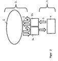
- FIG. 1 schematically illustrated embodiment of a tunable laser includes a first resonator 1, which contains an optical amplifying medium 4. Furthermore, the laser contains a second resonator 2, which is preferably a passive resonator, that is to say a resonator without an optical amplification medium. Between the first resonator 1 and the second resonator 2, a wavelength-selective optical filter 3 is arranged, which is tuned periodically and thus each to a specific Time is transparent for a certain wavelength range and allows for these wavelengths the transition from the first resonator into the second resonator, as indicated by the arrows 5.
- a wavelength-selective optical filter 3 is arranged, which is tuned periodically and thus each to a specific Time is transparent for a certain wavelength range and allows for these wavelengths the transition from the first resonator into the second resonator, as indicated by the arrows 5.
- the second resonator acts as an optical memory 6, in which the light circulates until the filter 3 is again tuned after a number of cycles in such a way that it is transparent for the specific wavelength.
- the light needs time T. for one complete revolution.
- the second resonator 2 In contrast to an optical delay path known from conventional FDML lasers, the second resonator 2 thus passes through several times, the number of rounds n being limited only by the optical losses occurring in the case of very many circulations.
- the first resonator 1, which contains the optically active medium 4 should be so short that the light during the time during which the optical filter 3 for a certain wavelength is transparent, can complete a full round in the first resonator. After a circulation in the first resonator, which is short in relation to the second resonator, the filter is therefore slightly or not detuned. It is possible that the light will be transmitted in two slightly different states of the filter if the filter is not phased out becomes. Thus, in this configuration, there is no perfect synchronization between the round trip time in the first resonator and the period t at which the filter 3 is tuned.
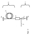
- FIG. 2 schematically shows an embodiment of a laser according to the invention, in which the coupling and decoupling of light from the first resonator 1 in the second resonator 2 and vice versa not by a single filter, but by two filters 3a, 3b is effected.
- light from the second resonator 2 acting as an optical memory 6 can be coupled through a first filter 3a into the first resonator 1, which contains the optical amplifier 4. After circulating through the first resonator 1, the light is coupled back into the second resonator 2 through the second filter 3b.
- the second filter 3b is tuned after a circulation time of the light by the first resonator 1 to the wavelength previously transmitted by the first filter 3a. In this way, a perfect synchronization can be achieved as with an FDML laser.
- the first resonator 1 is traversed by the light only once, in contrast to conventional laser resonators.
- the second resonator 2 includes an optical fiber 7.
- the fiber 7 is preferably a single-mode fiber.
- the fiber 7 may be a polarization-maintaining fiber to prevent a change in polarization state and to avoid instabilities.
- additional polarization controllers can also be used to produce a desired one Adjust polarization.
- the second resonator 2 is bounded on one side by a first mirror 8a, which may be, for example, a fiber Bragg grating, a metal mirror or a dielectric mirror, a Sagnac-type fiber mirror or a Faraday mirror ,
- a first mirror 8a which may be, for example, a fiber Bragg grating, a metal mirror or a dielectric mirror, a Sagnac-type fiber mirror or a Faraday mirror
- the second resonator 2 is limited by a tunable fiber Fabry-Perot (FFP-TF) filter 3 or an acousto-optically tunable fiber Bragg grating filter.
- FFP-TF tunable fiber Fabry-Perot
- a plano-concave type is preferably used, with the flat side facing the fiber 7. In this way, the intensity reflected back into the fiber is increased. With an orientation of the concave surface in the direction of the fiber 7 otherwise losses would occur.
- a filter is used in which the non-transmitted light is completely reflected back into the second resonator.
- the filter is preferably operated with a substantially periodic electronic waveform with low phase and amplitude noise (typically less than 80 dB).
- feedback loops can be used to stabilize the frequency with respect to the resonator length and thus compensate for thermally induced fluctuations.
- the first resonator 1 is limited by the tunable filter 3 and another mirror 8b.
- the optical amplifier 4 included in the first resonator may be, for example, a semiconductor optical amplifier (SOA).
- SOA semiconductor optical amplifier
- rare earth doped fiber amplifiers or nonlinear gain media.
- the frequency with which the optical filter 3 is modulated corresponds to a sub-harmonic of the rotational frequency in the second resonator 2.
- the possible tuning frequencies of the optical filter 3 at an optical path length of 300 m in the second resonator 2 are 500 KHz, 250 KHz, 166.66 KHz, 125 KHz, etc. but also 1 MHz, 1.5 MHz, etc.
- the light is coupled from the second resonator 2 after n round trips from the second resonator into the first resonator, amplified in the first resonator, and again coupled into the second resonator 2. After another n rounds, the light is again transmitted by the filter 3 and amplified again.
- the filter 3 preferably has a high transmission, preferably of more than 50%, and thus a low back reflection.
- FIG. 4 shows a modification of the in FIG. 3 illustrated embodiment in which within the first resonator 1, an optical coupler 10 is arranged, is coupled by the part of the laser radiation from the first resonator 1, as indicated by the arrow 9.
- the first resonator 1 includes an optical circulator 11.
- the circulator 11 serves as an optical switch, via which the annular part of the first resonator 1 is connected to the filter 3.
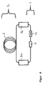
- FIG. 6 1 schematically shows an exemplary embodiment of a tunable laser, in which the second resonator 2 has at each end a filter 3a, 3b, in particular a Fabry-Perot filter, via which the second resonator 2 is coupled to the first resonator 1.
- the filters 3a, 3b can be synchronized such that they each have a transmission maximum after one revolution through the first resonator.
- This embodiment has the advantage that a time-shifted double passage of the light during coupling and decoupling from the first resonator is avoided.
- the first resonator includes an optical isolator 12 which is transparent only in the direction indicated by the arrow.
- a further insulator may be provided in the first resonator, wherein the insulators are preferably arranged on both sides of the optical amplification medium 4.
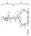
- FIG. 7 shows a bidirectional embodiment for improved polarization stabilization.
- the second resonator 2 includes a polarization controller 13.
- the first resonator 1 designed as a ring resonator and with a polarization-maintaining fiber 7a, also called a polarization maintaining fiber, comprises a polarization-dependent amplifying amplifier medium 4.
- the amplifier medium 4 may be, for example, an optical semiconductor amplifier, also referred to as a semiconductor optical amplifier or SOA.
- the amplifier medium 4 is designed such that it only amplifies light of a polarization direction, in accordance with the exemplary embodiment FIG. 8 For example, if this is light, it is horizontal with respect to the plane of the drawing Polarization direction 18a, symbolized by double arrows. Light with direction of polarization perpendicular to the plane 18b is symbolized by dots. The running direction of the light is indicated by arrows 17.
- An optical circulator 11 is located between the annular first resonator 1 and the filter 3 configured as a fiber Fabry-Perot.
- the circulator 11 in this case conducts light from connection A to connection B. Light entering the connection B exits from the connection C. off, and light entering port C will not be forwarded.
- the circulator 11 thus acts for light from the direction of the terminal C as an optical isolator. On the polarization direction of the light of the circulator 11 has no significant influence.
- the first resonator 1 Between terminal C of the circulator 11 and optical amplifier medium 4 is a 90 ° splice 16, which connects two ends of the polarization-maintaining fiber 7a with each other so that the ends are rotated by 90 ° to each other. That is, when passing through the 90 ° splice 16, the polarization direction 18a, 18b of the light is rotated 90 ° with respect to the plane of the drawing.
- the first resonator 1 further comprises an optical coupler 10.
- a polarization maintaining fiber 7b is also attached, the second end of which is connected to the filter 3.
- a first, the circulator 11 facing side of the filter 3 has a lower reflectivity than a second side of the filter 3, which faces the second resonator 2.
- the reflectivity of the first side is preferably less than 60%, more preferably less than 50%.
- the reflectivity of the second side is preferably more than 90%, particularly preferably more than 95%.
- the passive second resonator 2 is thus bounded on the one hand by the highly reflective second side of the filter 3, on the other hand by a mirror 8 designed as a Faraday mirror.
- the mirror 8 rotates the polarization direction 18a, 18b of the reflected light by 90 ° in comparison to the incident light.
- Filter 3 and mirror 8 are connected to each other via a fiber 7c.
- This fiber is configured as a single-mode fiber or as a polarization-maintaining fiber.
- the effect occurs that light with frequencies at the edge of the amplification range of the amplifier medium 4 is amplified only comparatively poorly compared to frequencies in the center of the amplification range. That is, if both light with frequencies in the center, and light with frequencies at the edge of the gain range in a laser resonator, so is almost exclusively the light amplified with frequencies in the center. This effect can lead to a reduced frequency bandwidth of a laser.
- the laser can, as in FIG. 8 represented, be constructed.
- the mode of operation is explained in more detail below. Since the amplifier amplifies 4 polarization selective, the light generated by the amplifier 4 know a certain direction of polarization 18 a, for example parallel to the plane of the drawing. This generated light passes to the circulator 11 and is passed from port A to port B and then passes to the filter 3.
- the tunable filter 3 is transmissive to the wavelength of the light at the time the light impinges. or (B) the filter 3 is blocking for the light, that is, a part of the light is lost, another part is reflected back towards the terminal B of the circulator 11 and passes through terminal C back into the ring-like part of the first resonator first
- the light is in the second resonator 2 until the filter 3 is again transmissive for the corresponding wavelength and the light is coupled into the first resonator 1.
- the light in the second resonator 2 runs in the direction of the mirror 8, it has, for example, a polarization direction 18a parallel to the plane of the drawing. If the light then hits the Faraday mirror 8, the light is reflected and its polarization direction is rotated by 90 ° so that the polarization direction 18b is then perpendicular to the plane of the drawing. Since the filter 3 has no polarization effect, the light is reflected with the polarization direction unchanged and runs back in the direction of the mirror 8, which again rotates the polarization direction by 90 ° in the case of reflection.
- the filter 3 is to be tuned with a period t such that the light is coupled into the first resonator 1 after an odd number of cycles in the second resonator 2, for example after 15 cycles.
- this light has a polarization direction 18b rotated by 90 ° with respect to the light emerging from the first resonator 1.
- This coupled light is passed from port B to port C of circulator 11 and passes to the 90 ° splice 16, again rotating the polarization direction 18b of the light by 90 °. After passing through the 90 ° -Sp dealtes 16, the polarization direction 18a of the light is thus again parallel to the plane. So the light reaches with the appropriate polarization direction 18a the amplifier medium 4, so that it is amplified by this.
- the filter 3 acts to block the light generated by the amplifier medium 4, that is, the filter 3 reflects the light back in the direction of the circulator 11 while maintaining its polarization direction 18a. That is, the light is in the embodiment according to FIG. 8 then polarized parallel to the plane of the drawing. From the circulator 11, the light is forwarded to the 90 ° splice 16 and the polarization of the light is rotated via this in a direction 18b perpendicular to the plane, whereupon this light from the amplifier medium 4 can not be amplified. Thus, only light can be amplified by the amplifier medium 4, which has completely passed through the second resonator 2 at least once. Thus, only with the tuning period t of the filter 3 synchronous wavelengths of light can be amplified, the gain of other wavelengths is suppressed. There is no significant narrowing of the gain bandwidth.
- the first resonator 1 passes through twice and thus twice through the 90 ° splice 16 undergoes a polarization rotation and thereby again has a polarization direction 18 a, which would be amplified by the amplifier medium 4 is also reflected twice from the filter 3. Since the filter 3 in blocking position in the direction of the circulator 11 has only a relatively low reflectivity, this light is also effectively suppressed and prevented amplification of this light.
- the first resonator 1 has optical isolators 12 which can be based on the Faraday effect and only light let pass in a running direction 17.
- the amplifier medium 4 may alternatively be designed as a non-polarization-dependent amplifying medium, but in this case is to be combined with a polarizer.
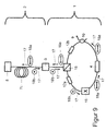
- a polarization-dependent reflecting beam splitter 15 also referred to as a polarizing beam splitter, short PBS, used.
- Light having, for example, a polarization direction 18a parallel to the plane of the drawing and reaching the beam splitter 15 is reflected in the direction of the filter 3.
- Light, for which the filter 3 is blocking, is reflected by the filter 3 back in the direction of the beam splitter 20, wherein the polarization direction 18a is maintained.
- Such light is then reflected back to the amplifier medium 4 by the beam splitter 20 on the same path as the incoming light and blocked by the optical isolator 12a.
- the polarization-dependent reflecting beam splitter 15 and the optical isolator 12a By the combination of the polarization-dependent reflecting beam splitter 15 and the optical isolator 12a, light of asynchronous wavelength at the period t of the filter 3 can be effectively suppressed even if the first side of the filter 3 should have high reflectivity for such light.
- a second isolator 12b may additionally be placed in the first resonator 1.
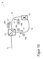
- FIG. 10 schematically a Sagnac-type fiber mirror is shown.
- a Sagnac-type fiber mirror may be used as a polarization-rotating mirror 8 as an alternative to a Faraday mirror.
- Light from the fiber 7c which is designed as a single-mode fiber or polarization-maintaining fiber, passes to a terminal A of a polarization-dependent reflective beam splitter 15.
- Light having a polarization direction 18a parallel to the plane is transmitted by the beam splitter 15 in the direction of port B, light having a polarization direction 18b perpendicular to the drawing plane is reflected in the direction of port C.
- the terminals B and C of the beam splitter 15 are connected to each other via polarization maintaining fibers 7e, 7f, wherein the fibers 7e, 7f are connected to each other via a 90 ° splice 16.
- the polarization direction 18a of the light which comes from terminal B of the beam splitter 15 and runs in the direction of connection C, is rotated by 90 °. Since the direction of polarization 18b is then perpendicular to the plane of the drawing, the light is reflected by the beam splitter 15 via connection A back into the fiber 7c. The same applies to light that runs from terminal C of the beam splitter 15 to terminal B.
- the polarization direction of the light passing through the arrangement can be rotated by 90 °.
- the difference in the lengths of the fibers 7e, 7f is preferably shorter than the so-called beat length, particularly preferably shorter than half the beat length.
- the difference in length between the fibers 7e, 7f is in particular less than 4 mm.
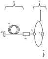
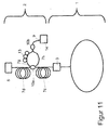
- FIG. 11 is schematically shown an embodiment in which the radiation 9 is coupled out in the second resonator 2.
- the first resonator is according to, for example FIG. 9 or FIG. 10 designed.
- an optical coupler 10a is attached, via which light is coupled out of the second resonator 2.
- the fibers 7c, 7d preferably have a similar length, more preferably they are the same length.
- two fibers 7g, 7h are attached.
- Light traveling in the second resonator 2 from the filter 3 in the direction of the mirror 8 is coupled into the fiber 7g and light, which in the second resonator 2 passes from the mirror 8 in the direction of the filter 3, into the fiber 7h.
- the polarization direction of the light in the fiber 7g can be adjusted so that the polarization direction corresponds to that of the light in the fiber 7h.
- the light from both fibers 7g, 7h can be combined.
- a polarization-dependent reflecting beam splitter in an arrangement analogous to that in FIG. 10 are used to combine the two partial beams of the fibers 7g, 7h together.
- the polarization controller 13 is not necessary.
- the outcoupled radiation 9 may have different polarization directions at different times, which may be desirable in some applications.
- a further alternative is to use a polarization-independent 50% beam splitter instead of polarization controller 13 and / or polarization-dependent beam splitter or coupler 10b.
- polarization controller 13 instead of polarization controller 13 and / or polarization-dependent beam splitter or coupler 10b.
- the coupling losses when merging the partial beams of the fibers 7g and 7h, however, are relatively high.
- the thus coupled-out radiation 9 can then optionally either be guided to a measuring station as required or further amplified by means of an active amplifier fiber or an optical semiconductor amplifier 14.
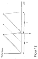
- FIG. 12 Another problem that can occur with a sub-harmonic FDML laser is in FIG. 12 illustrated.
- the transmission wavelength of the filter 3 or the wavelength of the light striking the filter 3 is plotted against time.
- the transmission wavelength of the filter 3 is shown as a solid line, the wavelength of the light incident on the filter 3 as a dashed line.
- the filter 3 is operated for example with a sawtooth voltage.
- the two edges of the sawtooth voltage preferably have a different pitch, so that the return of the filter 3 to a start position is faster than the tuning of the transmission wavelength.
- the filter 3 is driven back, it may happen that it has a transmission wavelength at which light is then transmitted through the filter 3 into the first resonator 1 during the retraction. In FIG. 12 this happens at the time ⁇ . This can lead to unwanted power fluctuations of the FDML laser.
- This effect can be avoided, for example, by suitably adapting the length of the second resonator 2 and the tuning period t of the filter 3 to one another.
- FIG. 13 shown schematically.
- the part of the fiber 7c belonging to the second resonator 2, with which the second side of the filter 3 is formed, is mechanically fixed.
- the first side of the filter 3, which is in communication with the fiber 7b, is movably supported.
- a longitudinal movement 19a in the beam direction which is responsible for the frequency tuning of the fiber Fabry-Perot filter 3 there is additionally a movement 19b with a component perpendicular to the transmission direction of the filter 3.
- the filter 3 or the end of the fiber 7b is temporarily shifted in this way in that the quality of the Fabry-Perot is reduced and no light can pass from the fiber 7b into the fiber 7c or vice versa.
- Such a two- or even three-dimensional movement of the first side of the filter 3 or the fiber 7b can be realized for example via a piezo drive.
Description
- Die Erfindung betrifft einen abstimmbaren Laser gemäß dem Oberbegriff des Patentanspruchs 1. Insbesondere wird ein kompakter, extrem schnell abstimmbarer, schmalbandiger Laser angegeben.
- Herkömmliche schnell abstimmbare Laser enthalten üblicherweise ein Lasermedium, welches Verstärkung über einen breiten Wellenlängenbereich aufweist und einen abstimmbaren optischen Bandpassfilter. Bei einer Erhöhung der Frequenz, mit welcher der optische Bandpassfilter abgestimmt wird, kann es vorkommen, dass die Laseraktivität aussetzt, weil das Licht im Resonator nicht mehr genügend Umläufe absolvieren kann, um eine gesättigte Laseraktivität aufzubauen, bevor der optische Bandpassfilter zu einer neuen Wellenlänge abgestimmt wird. Durch die Verwendung kürzerer Resonatorlängen kann dieses Problem nur bedingt gelöst werden, da bei kürzeren Resonatorlängen der Modenabstand des Lasers größer wird und verstärktes Rauschen auftritt.
- Zur Überwindung dieses Problems ist aus der Druckschrift
WO 2006/079078 A3 das Konzept der spektralen Modenkopplung (Fourier Domain Mode Locking - FDML) bekannt. Gemäß diesem Konzept wird der optische Filter synchron zur Umlaufzeit des Lichtes in dem Resonator abgestimmt. Das heißt, dass Licht einer bestimmten Wellenlänge nach einem Umlauf im Resonator wieder auf den optischen Filter trifft, wenn er wieder auf diese bestimmte Wellenlänge abgestimmt ist. Derartige FDML-Laser haben gegenüber herkömmlichen schnell abstimmbaren Lasern den Vorteil, dass keine fundamentale Beschränkung der Abstimmgeschwindigkeit besteht, und dass sie über eine schmälere Linienbreite und längere Koherenzlänge verfügen. Weiterhin weisen sie weniger Rauschen und mehr Leistung als herkömmliche schnell abstimmbare Laser auf und haben in der Regel keine diskrete Modenstruktur. - Ein Nachteil der bekannten FDML-Laser besteht aber darin, dass zur Synchronisation der Umlaufzeit in dem Resonator mit der Filterabstimmzeit eine sehr lange optische Verzögerungsstrecke verwendet wird. Als Verzögerungsstrecke wird in der Regel eine sehr lange Glasfaser verwendet. Bei einer Abstimmfrequenz des optischen Filters von 30 KHz ist beispielsweise eine 7 km lange Glasfaser erforderlich, um die Umlaufzeit in der Verzögerungsstrecke an die Abstimmfrequenz des Filters anzupassen. Durch die Verwendung derart langer Glasfasern entstehen vergleichsweise hohe Kosten. Weiterhin sind derartige FDML-Laser wegen der langen Glasfaser vergleichsweise groß.
- Der Erfindung liegt die Aufgabe zugrunde, einen verbesserten abstimmbaren Laser anzugeben, der sich insbesondere dadurch auszeichnet, dass er vergleichsweise kompakt kostengünstig herstellbar ist.
- Diese Aufgabe wird durch einen abstimmbaren Laser gemäß Patentanspruch 1 gelöst. Vorteilhafte Ausgestaltungen und Weiterbildungen der Erfindung sind Gegenstand der abhängigen Ansprüche.
- Ein abstimmbarer Laser gemäß der Erfindung enthält ein optisches Verstärkungsmedium, einen ersten Resonator und einen periodisch abstimmbaren optischen Filter, wobei der Laser einen zweiten Resonator enthält, in dem Licht einer Laserwellenlänge eine Umlaufzeit T aufweist, der optische Filter zwischen dem ersten Resonator und dem zweiten Resonator angeordnet ist und mit einer Periode t abgestimmt wird, für die gilt: t = (n / m) T, wobei n und m ganzzahlig sind und m / n nicht ganzzahlig ist.
- Der erste Resonator enthält das optische Verstärkungsmedium. Der erste Resonator muss nicht notwendigerweise einen Laserresonator im klassischen Sinn darstellen, sondern wird vorzugsweise von dem Laserlicht nur einmal durchlaufen. Anstelle der bei herkömmlichen FDML-Lasern verwendeten sehr langen optischen Verzögerungsstrecke enthält der Laser neben dem ersten Resonator einen zweiten Resonator, der mehrfach durchlaufen wird. Um einen mehrfachen Umlauf in dem zweiten Resonator zu erzielen, ist der optische Filter mit einer Frequenz synchronisiert, die einer subharmonischen, also einem Bruchteil der Umlauffrequenz des Lichts durch den zweiten Resonator, entspricht. Insbesondere ist die Umlaufzeit T = (m / n) t nicht gleich einem ganzzahligen Vielfachen der Periode t, mit der der optische Filter abgestimmt wird. Auf diese Weise wird erreicht, das Licht einer bestimmten Wellenlänge, das den zweiten Resonator durchläuft, beim nächsten Auftreffen auf den Filter von diesem nicht transmittiert wird, weil der Filter zu diesem Zeitpunkt auf eine andere Wellenlänge abgestimmt ist. Vielmehr ist der optische Filter erst nach n Umläufen des Lichts durch den zweiten Resonator wieder auf die bestimmte Wellenlänge abgestimmt.
- Die Anzahl der Umläufe des Lichts in dem zweiten Resonator beträgt vorzugsweise n ≥ 2, besonders bevorzugt n ≥ 10, insbesondere n ≥ 100.
- Der Laser hat zusätzlich zu den Vorteilen herkömmlicher FDML-Laser insbesondere den Vorteil, dass eine um einen Faktor n kürzere Faserlänge verwendet werden kann, wobei n die Anzahl der Umläufe in dem zweiten Resonator ist. Beispielsweise kann bei einer Anzahl von n = 100 Umläufen in dem zweiten Resonator eine 100-mal kürzere Glasfaser für den zweiten Resonator verwendet werden, als bei einem herkömmlichen FDML-Laser. Der Laser kann daher viel kompakter gestaltet werden und ist insbesondere im Fall von vorzugsweise verwendeten polarisationserhaltenden Spezialfasern wesentlich kostengünstiger.
- Weiterhin ist es vorteilhaft, dass der optische Filter in kleineren Frequenzintervallen abgestimmt werden kann, als bei einem herkömmlichen FDML-Laser. Die Abstimmfrequenz im Vergleich zu herkömmlichen FDML-Lasern vorteilhaft in kleinen Schritten durchstimmbar, beispielsweise in 1 %-Schritten bei einem 100-fachen Umlauf durch den zweiten Resonator.
- Beispielsweise kann ein herkömmlicher FDML-Laser mit einer 7 km langen Glasfaser mit einer Frequenz von 30 KHz oder höheren harmonischen davon, also 60 KHz, 90 KHz, 120 KHz usw., betrieben werden. Im Gegensatz dazu kann ein erfindungsgemäßer Laser, bei dem 100 Umläufe im Resonator stattfinden, beispielsweise mit Frequenzen von 30 KHz, 30,3 KHz, 30,6 KHz usw. betrieben werden.
- Das optische Verstärkungsmedium des Lasers ist vorzugsweise im ersten Resonator enthalten. Dagegen ist der zweite Resonator vorteilhafterweise ein passiver Resonator. Bei dem periodischen Abstimmen des optischen Filters können jeweils bestimmte Wellenlängen, die sich im jeweils eingestellten Transmissionsbereich des Filters befinden, aus dem ersten Resonator in den zweiten Resonator und zurück transmittiert werden. Diejenigen Wellenlängen, die von dem Filter nicht transmittiert werden, werden von dem Filter vorzugsweise annähernd vollständig in den zweiten Resonator zurückreflektiert. Dazu ist es vorteilhaft, wenn die Absorption des Filters vernachlässigbar klein ist. Insbesondere kann es sich bei dem optischen Filter um einen abstimmbaren Fabry-Perot-Filter handeln.
- Gemäß zumindest einer Ausführungsform des Lasers ist der optische Filter als Fabry-Perot-Filter ausgestaltet. Solche Filter sind effizient durchstimmbar und weisen eine hohe Güte auf.
- Gemäß zumindest einer Ausführungsform des Lasers ist der optische Filter während einer Abstimmperiode t zumindest zeitweise frequenzunabhängig sperrbar. Dies wird gemäß zumindest einer Ausführungsform des Lasers dadurch realisiert, dass der Filter senkrecht zu einer Transmissionsrichtung auslenkbar ist.
- Gemäß zumindest einer Ausführungsform des Lasers umfasst der zweite Resonator zumindest ein polarisationsdrehend wirkendes Element. Bevorzugt ist dieses Element mit einem Faraday-Spiegel oder mit einem Sagnac-Typ Faserspiegel gestaltet.
- Gemäß zumindest einer Ausführungsform des Lasers weist dieser im ersten Resonator mindestens ein polarisationsselektives Verstärkungsmedium auf. Über ein solches Verstärkungsmedium kann die Polarisation der verstärkten Strahlung effektiv eingestellt werden.
- Gemäß zumindest einer Ausführungsform des Lasers ist die Strahlung aus dem zweiten Resonator auskoppelbar. Hierdurch kann die Auskoppelfrequenz in einem weiten Bereich eingestellt werden.
- Gemäß zumindest einer Ausführungsform des Lasers umfasst dieser mindestens einen Nachverstärker. Über eine Nachverstärkung der aus dem ersten oder zweiten Resonator ausgekoppelten Strahlung können hohe optische Leistungen des Lasers erzielt werden.
- Gemäß zumindest einer Ausführungsform des Lasers weist der erste Resonator mindestens eine polarisationserhaltende Faser auf. Über eine solche Faser kann der Polarisationszustand des Lichts erhalten werden.
- Die Erfindung wird im Folgenden anhand der
Figuren 1 bis 13 näher erläutert. - Die
Figuren 1 bis 13 zeigen jeweils schematische Darstellungen von Ausführungsbeispielen eines erfindungsgemäßen abstimmbaren Lasers. - Gleiche oder gleich wirkende Elemente sind in den Figuren mit den gleichen Bezugszeichen versehen.
- Das in
Figur 1 schematisch dargestellte Ausführungsbeispiel eines abstimmbaren Lasers enthält einen ersten Resonator 1, der ein optisches Verstärkungsmedium 4 enthält. Weiterhin enthält der Laser einen zweiten Resonator 2, bei dem es sich vorzugsweise um einen passiven Resonator handelt, also einen Resonator ohne optisches Verstärkungsmedium. Zwischen dem ersten Resonator 1 und dem zweiten Resonator 2 ist ein wellenlängenselektiver optischer Filter 3 angeordnet, der periodisch abgestimmt wird und somit jeweils zu einem bestimmten Zeitpunkt für einen bestimmten Wellenlängenbereich transparent ist und für diese Wellenlängen den Übergang von dem ersten Resonator in den zweiten Resonator ermöglicht, wie es durch die Pfeile 5 angedeutet wird. Der zweite Resonator wirkt als optischer Speicher 6, in dem das Licht so lange zirkuliert, bis der Filter 3 nach einer Anzahl n Umläufen wieder derart abgestimmt ist, dass er für die bestimmte Wellenlänge transparent ist. In dem zweiten Resonator 2 benötigt das Licht für einen kompletten Umlauf die Zeit T. - Der Filter 3 ist mit einer Periode t abgestimmt, die die Bedingung t = (n / m) T erfüllt, wobei n und m von 0 verschiedene ganze Zahlen sind. Der Wert m / n ist nicht ganzzahlig, sodass die Umlaufzeit T = (m / n) t in dem zweiten Resonator nicht einem ganzzahligen Vielfachen der Periode t des optischen Filters entspricht. Nachdem eine bestimmte Wellenlänge durch den Filter 3 transmittiert wurde, ist der Filter daher nicht bereits nach einem Umlauf durch den zweiten Resonator 2 wieder transparent, sondern erst nach einer Anzahl von n Umläufen. Im Gegensatz zu einer von herkömmlichen FDML-Lasern bekannten optischen Verzögerungsstrecke wird der zweite Resonator 2 also mehrfach durchlaufen, wobei die Anzahl der Umläufe n nach oben nur durch die bei sehr vielen Umläufen auftretenden optischen Verluste begrenzt ist. Der erste Resonator 1, der das optisch aktive Medium 4 enthält, sollte derart kurz sein, dass das Licht während der Zeit, während der der optische Filter 3 für eine bestimmte Wellenlänge transparent ist, einen vollen Umlauf in dem ersten Resonator absolvieren kann. Nach einem Umlauf in dem im Verhältnis zum zweiten Resonator kurzen ersten Resonator ist der Filter also geringfügig oder gar nicht verstimmt. Es ist möglich, dass das Licht in zwei geringfügig verschiedenen Zuständen des Filters transmittiert wird, wenn der Filter nicht stufenweise durchgestimmt wird. In dieser Konfiguration liegt also keine perfekte Synchronisation zwischen der Umlaufzeit in dem ersten Resonator und der Periode t, mit der der Filter 3 abgestimmt wird, vor.
- Um eine bessere Synchronisation zu erzielen, kann ein Aufbau mit zwei oder mehr Filtern verwendet werden.
Figur 2 zeigt schematisch ein Ausführungsbeispiel eines erfindungsgemäßen Lasers, bei dem das Einkoppeln und Auskoppeln von Licht aus dem ersten Resonator 1 in den zweiten Resonator 2 und umgekehrt nicht von einem einzigen Filter, sondern von zwei Filtern 3a, 3b bewirkt wird. Bei dieser Ausführungsform kann Licht aus dem als optischen Speicher 6 wirkenden zweiten Resonator 2 durch einen ersten Filter 3a in den ersten Resonator 1, der den optischen Verstärker 4 enthält, eingekoppelt werden. Nach einem Umlauf durch den ersten Resonator 1 wird das Licht durch den zweiten Filter 3b wieder in den zweiten Resonator 2 eingekoppelt. Der zweite Filter 3b ist nach einer Umlaufzeit des Lichts durch den ersten Resonator 1 auf die Wellenlänge abgestimmt, die zuvor von dem ersten Filter 3a transmittiert wurde. Auf diese Weise kann eine perfekte Synchronisation wie bei einem FDML-Laser erzielt werden. Der erste Resonator 1 wird von dem Licht im Gegensatz zu herkömmlichen Laserresonatoren nur einmal durchlaufen. - Bei dem in
Figur 3 schematisch dargestellten Ausführungsbeispiel enthält der zweite Resonator 2 eine optische Faser 7. Die Faser 7 ist vorzugsweise eine Einmoden-Faser. Insbesondere kann es sich bei der Faser 7 um eine polarisations-erhaltende Faser handeln, um eine Veränderung des Polarisationszustands zu verhindern und um Instabilitäten zu vermeiden. Im Falle einer Standard-Einmoden-Faser können auch zusätzliche Polarisations-Controller verwendet werden, um eine gewünschte Polarisation einzustellen. Der zweite Resonator 2 wird auf der einen Seite durch einen ersten Spiegel 8a begrenzt, bei dem es sich beispielsweise um ein Faser-Bragg-Gitter, einen Metallspiegel oder einen dielektrischen Spiegel, einen Sagnac-Typ-Faserspiegel oder um einen Faraday-Spiegel handeln kann. Auf der anderen Seite wird der zweite Resonator 2 durch einen abstimmbaren Faser-Fabry-Perot-Filter 3 (FFP-TF, Fiber Fabry Perot Tunable Filter) oder einen akustooptisch abstimmbaren Faser-Bragg-Gitter-Filter begrenzt. Bei der Verwendung eines FFP-TF-Filters 3 wird vorzugsweise ein plan-konkaver Typ verwendet, wobei die plane Seite zur Faser 7 gerichtet ist. Auf diese Weise wird die in die Faser zurückreflektierte Intensität erhöht. Bei einer Orientierung der konkaven Oberfläche in Richtung zur Faser 7 würden ansonsten Verluste auftreten. Bevorzugt wird also ein Filter verwendet, bei dem das nicht transmittierte Licht vollständig in den zweiten Resonator zurückreflektiert wird. Der Filter wird vorzugsweise mit einer im Wesentlichen periodischen elektronischen Wellenform mit geringem Phasen- und Amplitudenrauschen (in der Regel weniger als 80 dB) betrieben. Dabei können Rückkopplungsschleifen verwendet werden, um die Frequenz in Bezug auf die Resonatorlänge zu stabilisieren und auf diese Weise thermisch bedingte Schwankungen auszugleichen. - Der erste Resonator 1 wird durch den abstimmbaren Filter 3 und einen weiteren Spiegel 8b begrenzt. In dem ersten Resonator 1 wird ein Teil des Lichts, das in diesem verstärkt wird, ausgekoppelt, wie in
Figur 3 durch den Pfeil 9 angedeutet wird. Der in dem ersten Resonator enthaltene optische Verstärker 4 kann beispielsweise ein optischer Halbleiter-Verstärker (SOA - Semiconductor Optical Amplifier) sein. Alternativ können auch mit seltenen Erden dotierte Faserverstärker, oder auch nichtlineare Verstärkungsmedien verwendet werden. - Die Frequenz, mit der der optische Filter 3 moduliert ist, entspricht einer sub-harmonischen der Umlauffrequenz in dem zweiten Resonator 2. Beispielsweise betragen die möglichen Abstimmfrequenzen des optischen Filters 3 bei einer optischen Weglänge von 300 m in dem zweiten Resonator 2 500 KHz, 250 KHz, 166,66 KHz, 125 KHz usw. aber auch 1 MHz, 1,5 MHz usw. Das Licht wird aus dem zweiten Resonator 2 nach n Umläufen aus dem zweiten Resonator in den ersten Resonator eingekoppelt, in dem ersten Resonator verstärkt, und wieder in den zweiten Resonator 2 eingekoppelt. Nach weiteren n Umläufen wird das Licht erneut von dem Filter 3 transmittiert und wieder verstärkt. In dem Transmissionsbereich weist der Filter 3 vorzugsweise eine hohe Transmission, vorzugsweise von mehr als 50 %, und somit eine niedrige Rückreflexion auf.
-
Figur 4 zeigt eine Abwandlung des inFigur 3 dargestellten Ausführungsbeispiels, bei dem innerhalb des ersten Resonators 1 ein optischer Koppler 10 angeordnet ist, durch den ein Teil der Laserstrahlung aus dem ersten Resonator 1 ausgekoppelt wird, wie durch den Pfeil 9 angedeutet wird. - Bei dem in
Figur 5 dargestellten Ausführungsbeispiel enthält der erste Resonator 1 einen optischen Zirkulator 11. Der Zirkulator 11 dient als optische Weiche, über die der ringförmige Teil des ersten Resonators 1 mit dem Filter 3 verbunden ist. -
Figur 6 zeigt schematisch ein Ausführungsbeispiel eines abstimmbaren Lasers, bei dem der zweite Resonator 2 an beiden Enden jeweils einen Filter 3a, 3b, insbesondere Fabry-Perot-Filter, aufweist, über die der zweite Resonator 2 an den ersten Resonator 1 gekoppelt ist. Bei dieser Ausführungsform können die Filter 3a, 3b derart synchronisiert werden, dass sie nach einem Umlauf durch den ersten Resonator jeweils ein Transmissionsmaximum aufweisen. Diese Ausführungsform hat den Vorteil, dass ein zeitlich versetzter doppelter Durchgang des Lichts beim Ein- und Auskoppeln aus dem ersten Resonator vermieden wird. Der erste Resonator enthält einen optischen Isolator 12, der nur in der durch den Pfeil angedeuteten Richtung transparent ist. Optional kann ein weiterer Isolator (nicht dargestellt) in dem ersten Resonator vorgesehen sein, wobei die Isolatoren vorzugsweise beidseitig des optischen Verstärkungsmediums 4 angeordnet sind. -
Figur 7 zeigt eine bidirektionale Ausführungsform für eine verbesserte Stabilisierung der Polarisation. Der zweite Resonator 2 enthält einen Polarisationscontroller 13. - Aufgrund des Mehrfachdurchgangs durch den zweiten Resonator 2 wird die Wirkung eines Polarisationscontrollers 13 oder eines Dispersions-Kompensators vervielfacht.
- In
Figur 8 ist ein weiteres Ausführungsbeispiel schematisch dargestellt. Der als Ringresonator und mit einer polarisationserhaltenden Faser 7a, auch als polarization maintaining fiber bezeichnet, gestaltete erste Resonator 1 umfasst ein polarisationsabhängig verstärkendes Verstärkermedium 4. Als Verstärkermedium 4 kann beispielsweise ein optischer Halbleiterverstärker, auch als Semiconductor Optical Amplifier oder SOA bezeichnet, dienen. Das Verstärkermedium 4 ist so ausgestaltet, dass es nur Licht einer Polarisationsrichtung verstärkt, im Ausführungsbeispiel gemäßFigur 8 ist dies beispielsweise Licht mit bezüglich der Zeichnungsebene horizontaler Polarisationsrichtung 18a, symbolisiert durch Doppelpfeile. Licht mit zur Zeichenebene senkrechter Polarisationsrichtung 18b ist durch Punkte symbolisiert. Die Laufrichtung des Lichts ist durch Pfeile 17 angedeutet. - Zwischen ringförmigen ersten Resonator 1 und dem als Faser-Fabry-Perot ausgestalteten Filter 3 befindet sich ein optischer Zirkulator 11. Der Zirkulator 11 leitet hierbei Licht von Anschluss A zu Anschluss B. Licht, das in den Anschluss B eintritt, tritt aus dem Anschluss C aus, und Licht, das den Anschluss C betritt, wird nicht weitergeleitet. Der Zirkulator 11 wirkt also für Licht aus Richtung hin zum Anschluss C als optischer Isolator. Auf die Polarisationsrichtung des Lichts hat der Zirkulator 11 keinen wesentlichen Einfluss.
- Zwischen Anschluss C des Zirkulators 11 und optischem Verstärkermedium 4 befindet sich ein 90°-Spleiß 16, der zwei Enden der polarisationserhaltenden Faser 7a derart miteinander verbindet, dass die Enden zueinander um 90° gedreht sind. Das heißt, beim Durchlaufen des 90°-Spleißes 16 wird die Polarisationsrichtung 18a, 18b des Lichts bezüglich der Zeichenebene um 90° gedreht. Zum Auskoppeln der Strahlung 9 weist der erste Resonator 1 weiterhin einen optischen Koppler 10 auf.
- An Anschluss B des Zirkulators 11 ist eine ebenfalls polarisationserhaltende Faser 7b angebracht, deren zweites Ende mit dem Filter 3 verbunden ist. Eine erste, dem Zirkulator 11 zugewandte Seite des Filters 3 weist eine geringere Reflektivität auf als eine zweite Seite des Filters 3, die dem zweiten Resonator 2 zugewandt ist. Die Reflektivität der ersten Seite liegt bevorzugt bei unter 60 %, besonders bevorzugt bei unter 50 %. Die Reflektivität der zweiten Seite liegt bevorzugt bei über 90 %, besonders bevorzugt bei über 95 %.
- Der passive zweite Resonator 2 wird also einerseits von der hochreflektierenden zweiten Seite des Filters 3 begrenzt, andererseits von einem als Faraday-Spiegel gestalteten Spiegel 8. Der Spiegel 8 dreht die Polarisationsrichtung 18a, 18b des reflektierten Lichts um 90° im Vergleich zum einfallenden Licht. Filter 3 und Spiegel 8 sind über eine Faser 7c miteinander verbunden. Diese Faser ist als Einmodenfaser oder als polarisationserhaltende Faser ausgestaltet.
- Insbesondere bei spektral breitbandigen Lasern tritt der Effekt auf, dass Licht mit Frequenzen am Rande des Verstärkungsbereichs des Verstärkermediums 4 gegenüber Frequenzen im Zentrum des Verstärkungsbereichs nur vergleichsweise schlecht verstärkt wird. Das heißt, befindet sich sowohl Licht mit Frequenzen im Zentrum, als auch Licht mit Frequenzen am Rande des Verstärkungsbereichs in einem Laserresonator, so wird fast ausschließlich das Licht mit Frequenzen im Zentrum verstärkt. Dieser Effekt kann zu einer reduzierten Frequenzbandbreite eines Lasers führen.
- Um im Falle eines sub-harmonischen FDML-Lasers diesen Effekt zu unterbinden, kann der Laser, wie in
Figur 8 dargestellt, aufgebaut sein. Die Funktionsweise wird im Folgenden näher erläutert. Da der Verstärker 4 polarisationsselektiv verstärkt, weißt das vom Verstärker 4 generierte Licht eine bestimmte Polarisationsrichtung 18a auf, beispielsweise parallel zur Zeichenebene. Dieses generierte Licht gelangt zum Zirkulator 11 und wird von Anschluss A zu Anschluss B weitergeleitet und gelangt anschließend zum Filter 3. Hier können zwei Fälle auftreten: (A) Der abstimmbare Filter 3 ist zum Zeitpunkt des Auftreffens des Lichts transmittierend für die Wellenlänge des Lichts, oder (B) der Filter 3 wirkt sperrend für das Licht, das heißt, ein Teil des Lichts geht verloren, ein weiterer Teil wird zurück in Richtung Anschluss B des Zirkulators 11 reflektiert und läuft über Anschluss C zurück in den ringartigen Teil des ersten Resonators 1. - Im Falle (A) befindet sich das Licht im zweiten Resonator 2, bis der Filter 3 für die entsprechende Wellenlänge wieder transmittierend ist und das Licht in den ersten Resonator 1 gekoppelt wird. Läuft das Licht im zweiten Resonator 2 in Richtung Spiegel 8, so hat es beispielsweise eine Polarisationsrichtung 18a parallel zur Zeichenebene. Trifft das Licht dann auf den Faraday-Spiegel 8, so wird das Licht reflektiert und dabei dessen Polarisationsrichtung um 90° gedreht, so dass die Polarisationsrichtung 18b dann senkrecht zur Zeichenebene ist. Da der Filter 3 keinen Polarisationseffekt aufweist, wird das Licht mit unveränderter Polarisationsrichtung reflektiert und läuft zurück in Richtung Spiegel 8, der die Polarisationsrichtung bei Reflexion erneut um 90° dreht.
- Der Filter 3 ist so mit einer Periode t abzustimmen, dass das Licht in den ersten Resonator 1 nach einer ungeraden Anzahl Umläufen im zweiten Resonator 2 eingekoppelt wird, zum Beispiel nach 15 Umläufen. Dieses Licht weist also beim Eintreten in den ersten Resonator 1 eine um 90° gegenüber dem aus dem ersten Resonator 1 austretenden Licht gedrehte Polarisationsrichtung 18b auf.
- Dieses einkoppelte Licht wird von Anschluss B auf Anschluss C des Zirkulators 11 geleitet und gelangt zum 90°-Spleiß 16, wodurch die Polarisationsrichtung 18b des Lichts erneut um 90° gedreht wird. Nach Durchlaufen des 90°-Speißes 16 ist die Polarisationsrichtung 18a des Lichts also wieder parallel zur Zeichenebene. Das Licht erreicht also mit der passenden Polarisationsrichtung 18a das Verstärkermedium 4, so dass es von diesem verstärkt wird.
- Im Falle (B) wirkt der Filter 3 für das vom Verstärkermedium 4 erzeugte Licht sperrend, das heißt, vom Filter 3 wird das Licht in Richtung Zirkulator 11 zurückreflektiert, wobei dessen Polarisationsrichtung 18a erhalten bleibt. Das heißt, das Licht ist im Ausführungsbeispiel gemäß
Figur 8 dann parallel zur Zeichenebene polarisiert. Vom Zirkulator 11 wird das Licht zum 90°-Spleiß 16 weitergeleitet und die Polarisation des Lichts über diesen in eine Richtung 18b senkrecht zur Zeichenebene gedreht, woraufhin dieses Licht vom Verstärkermedium 4 nicht verstärkt werden kann. Es kann also vom Verstärkermedium 4 nur Licht verstärkt werden, das den zweiten Resonator 2 mindestens einmal komplett durchlaufen hat. Es können also nur mit der Abstimmperiode t des Filters 3 synchrone Lichtwellenlängen verstärkt werden, die Verstärkung anderer Wellenlängen ist unterdrückt. Es tritt keine signifikante Verschmälerung der Verstärkungsbandbreite auf. - Licht mit zur Abstimmperiode t des Filters 3 asynchronen Wellenlängen, das den ersten Resonator 1 beispielsweise zwei Mal durchläuft und somit über den 90°-Spleiß 16 zwei Mal eine Polarisationsdrehung erfährt und hierdurch wieder eine Polarisationsrichtung 18a aufweist, die vom Verstärkermedium 4 verstärkt würde, wird auch zwei Mal vom Filter 3 reflektiert. Da der Filter 3 in Sperrstellung in Richtung Zirkulator 11 nur eine relativ geringe Reflektivität aufweist, wird dieses Licht ebenfalls effektiv unterdrückt und eine Verstärkung dieses Lichts unterbunden.
- Optional weist der erste Resonator 1 optische Isolatoren 12 auf, die auf dem Faraday-Effekt beruhen können und nur Licht in einer Laufrichtung 17 passieren lassen. Das Verstärkermedium 4 kann alternativ auch als nicht polarisationsabhängig verstärkendes Medium gestaltet sein, ist jedoch in diesem Falle mit einem Polarisator zu kombinieren.
- Das Ausführungsbeispiel gemäß
Figur 9 entspricht im Wesentlichen dem inFigur 8 gezeigten. Anstelle des Zirkulators 11 ist allerdings ein polarisationsabhängig reflektierender Strahlteiler 15, auch als Polarizing Beam Splitter, kurz PBS, bezeichnet, eingesetzt. Licht, das beispielsweise eine Polarisationsrichtung 18a parallel zur Zeichenebene aufweist und zum Strahlteiler 15 gelangt, wird in Richtung Filter 3 reflektiert. Licht, für das der Filter 3 sperrend ist, wird vom Filter 3 zurück in Richtung Strahlteiler 20 reflektiert, wobei dessen Polarisationsrichtung 18a erhalten bleibt. Solches Licht wird vom Strahlteiler 20 dann auf demselben Weg wie das einlaufende Licht zurück in Richtung Verstärkermedium 4 reflektiert und durch den optischen Isolator 12a geblockt. - Licht, das vom Strahlteiler 15 reflektiert, vom Filter 3 transmittiert und im zweiten Resonator 2 eine ungerade Anzahl von Umläufen macht, weist eine um 90° gedrehte Polarisation auf, so dass es nach Verlassen des zweiten Resonators 2 vom Strahlteiler 15 transmittiert wird, über den 90°-Spleiß 16 eine Drehung der Polarisationsrichtung 18a, 18b um 90° erfährt und verstärkt werden kann. Über die Kombination von polarisationsabhängig reflektierendem Strahlteiler 15 und optischem Isolator 12a kann Licht mit zur Periode t des Filters 3 asynchroner Wellenlänge auch dann effektiv unterdrückt werden, falls die erste Seite des Filters 3 eine hohe Reflektivität für solches Licht aufweisen sollte. Optional kann zusätzlich ein zweiter Isolator 12b im ersten Resonator 1 platziert werden.
- In
Figur 10 ist schematisch ein Sagnac-Typ-Faserspiegel dargestellt. Ein Sagnac-Typ-Faserspiegel kann alternativ zu einem Faraday-Spiegel als polarisationsdrehender Spiegel 8 eingesetzt werden. Licht aus der Faser 7c, die als Einmodenfaser oder als polarisationserhaltende Faser gestaltet ist, gelangt zu einem Anschluss A eines polarisationsabhängig reflektierenden Strahlteilers 15. Licht mit einer Polarisationsrichtung 18a parallel zur Zeichenebene wird vom Strahlteiler 15 in Richtung Anschluss B transmittiert, Licht mit einer Polarisationsrichtung 18b senkrecht zur Zeichenebene wird in Richtung Anschluss C reflektiert. Die Anschlüsse B und C des Strahlteilers 15 sind über polarisationserhaltende Fasern 7e, 7f miteinander verbunden, wobei die Fasern 7e, 7f über einen 90°-Spleiß 16 miteinander verbunden sind. Über diesen 90°-Spleiß 16 wird die Polarisationsrichtung 18a des Lichts, das von Anschluss B des Strahlteilers 15 kommt und in Richtung Anschluss C läuft, um 90° gedreht. Da dann die Polarisationsrichtung 18b senkrecht zur Zeichenebene ist, wird das Licht vom Strahlteiler 15 über Anschluss A zurück in die Faser 7c reflektiert. Analoges gilt für Licht, das von Anschluss C des Strahlteilers 15 zu Anschluss B läuft. Über eine derartige Anordnung kann also die Polarisationsrichtung des die Anordnung durchlaufenden Lichts um 90° gedreht werden. Die Differenz der Längen der Fasern 7e, 7f ist bevorzugt kürzer als die so genannte Beat-Länge, besonders bevorzugt kürzer als die halbe Beat-Länge. Die Längendifferenz zwischen den Fasern 7e, 7f ist insbesondere kleiner als 4 mm. - In
Figur 11 ist schematisch ein Ausführungsbeispiel gezeigt, bei dem die Strahlung 9 im zweiten Resonator 2 ausgekoppelt wird. Der erste Resonator ist zum Beispiel gemäßFigur 9 oderFigur 10 gestaltet. Zwischen zwei bevorzugt als polarisationserhaltende oder Einmodenfasern ausgestalteten Faser 7c, 7d ist ein optischer Koppler 10a angebracht, über den Licht aus dem zweiten Resonator 2 ausgekoppelt wird. Die Fasern 7c, 7d weisen bevorzugt eine ähnliche Länge auf, besonders bevorzugt sind sie gleich lang. Am Koppler 10a sind zwei Fasern 7g, 7h angebracht. Licht, das im zweiten Resonator 2 vom Filter 3 in Richtung Spiegel 8 läuft, wird in die Faser 7g eingekoppelt und Licht, das im zweiten Resonator 2 vom Spiegel 8 in Richtung Filter 3 läuft, in die Faser 7h. Über Polarisationscontroller 13 kann die Polarisationsrichtung des Lichts in der Faser 7g so eingestellt werden, dass die Polarisationsrichtung der des Lichts in der Faser 7h entspricht. Über einen weiteren Faserkoppler 10b kann das Licht aus beiden Fasern 7g, 7h vereinigt werden. - Anstelle eines zweiten Kopplers 10b kann alternativ auch ein polarisationsabhängig reflektierender Strahlteiler in einer Anordnung analog zu der in
Figur 10 gezeigten verwendet werden, um die beiden Teilstrahlen aus den Fasern 7g, 7h miteinander zu kombinieren. Im diesem Fall ist auch der Polarisationscontroller 13 nicht notwendig. Allerdings kann dann die ausgekoppelte Strahlung 9 zu verschiedenen Zeitpunkten unterschiedliche Polarisationsrichtungen aufweisen, was in einigen Anwendungen erwünscht sein kann. - Eine weitere Alternative besteht darin, anstelle von Polarisationscontroller 13 und/oder polarisationsabhängigen Strahlteiler beziehungsweise Koppler 10b einen polarisationsunabhängigen 50 % Strahlteiler zu verwenden. In diesem Falle sind die Koppelverluste beim Zusammenführen der Teilstrahlen aus den Fasern 7g und 7h allerdings relativ hoch.
- Die so ausgekoppelte Strahlung 9 kann anschließend optional je nach Erfordernissen entweder zu einem Messplatz geführt werden oder etwa mittels einer aktiven Verstärkerfaser oder eines optischen Halbleiterverstärkers 14 weiter verstärkt werden.
- Die Ausführungsbeispiele, etwa gemäß
Figur 7 undFigur 11 , können auch miteinander kombiniert werden. - Ein weiteres Problem, das bei einem sub-harmonischen FDML-Laser auftreten kann, ist in
Figur 12 illustriert. Hierbei ist die Transmissionswellenlänge des Filters 3 beziehungsweise die Wellenlänge des auf dem Filter 3 treffenden Lichts gegenüber der Zeit auftragen. Die Transmissionswellenlänge des Filters 3 ist als durchgezogene Linie dargestellt, die Wellenlänge des Lichts, das auf den Filter 3 trifft, als Strichlinie. Der Filter 3 wird beispielsweise mit einer Sägezahnspannung betrieben. Die beiden Flanken der Sägezahnspannung weisen bevorzugt eine unterschiedliche Steigung auf, so dass das Zurückfahren des Filters 3 in eine Startposition schneller geschieht, als das Durchstimmen der Transmissionswellenlänge. Beim Zurückfahren des Filters 3 kann es geschehen, dass dieser eine Transmissionswellenlänge aufweist, bei der dann während des Zurückfahrens Licht durch den Filter 3 in den ersten Resonator 1 transmittiert wird. InFigur 12 geschieht dies zum Zeitpunkt τ. Dies kann zu unerwünschten Leistungsschwankungen des FDML-Lasers führen. Dieser Effekt kann beispielsweise dadurch vermieden werden, dass die Länge des zweiten Resonators 2 und die Abstimmperiode t des Filters 3 in geeigneter Weise aufeinander angepasst werden. - Eine alternative Möglichkeit besteht darin, dass der Filter 3 in Zeitbereichen, in denen eine Transmission von Licht durch den Filter 3 hindurch unerwünscht ist, nicht transmittierend wirkt. Eine Möglichkeit, dies zu realisieren, ist in
Figur 13 schematisch dargestellt. Zum Beispiel der zum zweiten Resonator 2 gehörende Teil der Faser 7c, mit dem die zweite Seite des Filters 3 gebildet ist, ist mechanisch fixiert. Die erste Seite des Filters 3, die mit der Faser 7b in Verbindung steht, ist beweglich gelagert. Neben einer für die Frequenzabstimmung des Faser-Fabry-Perot-Filters 3 verantwortlichen Längsbewegung 19a in Strahlrichtung erfolgt zusätzlich eine Bewegung 19b mit einer Komponente senkrecht zur Transmissionsrichtung des Filters 3. Das heißt, der Filter 3 beziehungsweise das Ende der Faser 7b wird zeitweise so verschoben, dass die Qualität des Fabry-Perots verringert wird und kein Licht von der Faser 7b in die Faser 7c, beziehungsweise umgekehrt, treten kann. Eine solche zwei- oder auch dreidimensionale Bewegung der ersten Seite des Filters 3 beziehungsweise der Faser 7b kann beispielsweise über eine Piezoansteuerung realisiert werden.
Claims (15)
- Abstimmbarer Laser mit einem optischen Verstärkungsmedium (4), einem das optische Verstärkungsmedium (4) enthaltenden ersten Resonator (1) und mindestens einem periodisch abstimmbaren optischen Filter (3),
dadurch gekennzeichnet, dass- der Laser einen zweiten Resonator (2) enthält, in dem Licht aus dem ersten Resonator (1) einer Laserwellenlänge eine Umlaufzeit T aufweist,- der optische Filter (3) zwischen dem ersten Resonator (1) und dem zweiten Resonator (2) angeordnet ist und der abstimmbare Laser derart ausgelegt ist, dass der optische Filter (3) mit einer Periode t abgestimmt wird, und- für die Periode t gilt:
wobei n und m von Null verschiedene ganze Zahlen sind und m / n nicht ganzzahlig ist,- und der abstimmbare Laser derart ausgelegt ist, dass während der Periode t der zweite Resonator (2) mehrfach von dem Licht der Laserwellenlänge durchlaufen wird. - Abstimmbarer Laser nach Anspruch 1,
dadurch gekennzeichnet, dass
n ≥ 2 ist. - Abstimmbarer Laser nach Anspruch 1 oder 2,
dadurch gekennzeichnet, dass
der erste Resonator (1) und der zweite Resonator (2) je an mindestens einer Seite durch den optischen Filter (3) begrenzt sind. - Abstimmbarer Laser nach Anspruch 3,
dadurch gekennzeichnet, dass
der abstimmbare Laser derart ausgelegt ist, dass der erste Resonator (1) während der Periode t nur einmal von dem Licht der Laserwellenlänge durchlaufen wird. - Abstimmbarer Laser nach einem der vorhergehenden Ansprüche,
dadurch gekennzeichnet, dass
der zweite Resonator (2) ein passiver Resonator ist. - Abstimmbarer Laser nach einem der vorhergehenden Ansprüche,
dadurch gekennzeichnet, dass
der zweite Resonator (2) mindestens eine optische Faser (7) enthält. - Abstimmbarer Laser nach einem der vorhergehenden Ansprüche,
dadurch gekennzeichnet, dass
der optische Filter (3) ein abstimmbarer Faser-Fabry-Perot-Filter ist. - Abstimmbarer Laser nach einem der vorhergehenden Ansprüche,
dadurch gekennzeichnet, dass
der optische Filter (3) während einer Periode t zeitweise frequenzunabhängig sperrbar ist. - Abstimmbarer Laser nach Anspruch 8,
dadurch gekennzeichnet, dass
der optische Filter (3) senkrecht zu einer Transmissionsrichtung auslenkbar ist. - Abstimmbarer Laser nach einem der vorhergehenden Ansprüche,
dadurch gekennzeichnet, dass
der zweite Resonator (2) mindestens ein polarisationsdrehend wirkendes Element umfasst. - Abstimmbarer Laser nach Anspruch 10,
dadurch gekennzeichnet, dass
zumindest ein polarisationsdrehend wirkendes Element ein Faraday-Spiegel oder ein Sagnac-Typ Faserspiegel ist. - Abstimmbarer Laser nach einem der vorhergehenden Ansprüche,
dadurch gekennzeichnet, dass der erste Resonator (1) mindestens ein polarisationsselektives Verstärkungsmedium (4) aufweist. - Abstimmbarer Laser nach einem der vorhergehenden Ansprüche,
dadurch gekennzeichnet, dass
die Strahlung aus dem zweiten Resonator (2) auskoppelbar ist. - Abstimmbarer Laser nach einem der vorhergehenden Ansprüche,
dadurch gekennzeichnet, dass
der Laser zumindest einen Nachverstärker (14) aufweist. - Abstimmbarer Laser nach einem der vorhergehenden Ansprüche,
dadurch gekennzeichnet, dass
der erste Resonator (1) zumindest eine polarisationserhaltende Faser aufweist.
Applications Claiming Priority (2)
| Application Number | Priority Date | Filing Date | Title |
|---|---|---|---|
| DE102007021313 | 2007-05-07 | ||
| PCT/DE2008/000766 WO2008135034A1 (de) | 2007-05-07 | 2008-05-05 | Abstimmbarer laser |
Publications (2)
| Publication Number | Publication Date |
|---|---|
| EP2147488A1 EP2147488A1 (de) | 2010-01-27 |
| EP2147488B1 true EP2147488B1 (de) | 2014-03-26 |
Family
ID=39688804
Family Applications (1)
| Application Number | Title | Priority Date | Filing Date |
|---|---|---|---|
| EP08758025.4A Not-in-force EP2147488B1 (de) | 2007-05-07 | 2008-05-05 | Abstimmbarer laser |
Country Status (4)
| Country | Link |
|---|---|
| US (1) | US8130802B2 (de) |
| EP (1) | EP2147488B1 (de) |
| DE (1) | DE112008001852A5 (de) |
| WO (1) | WO2008135034A1 (de) |
Families Citing this family (15)
| Publication number | Priority date | Publication date | Assignee | Title |
|---|---|---|---|---|
| DE102008045634A1 (de) * | 2008-09-03 | 2010-03-04 | Ludwig-Maximilians-Universität München | Wellenlängenabstimmbare Lichtquelle |
| DE102009048216A1 (de) * | 2009-06-05 | 2010-12-09 | Toptica Photonics Ag | Abstimmbare Lichtquelle |
| US8526472B2 (en) | 2009-09-03 | 2013-09-03 | Axsun Technologies, Inc. | ASE swept source with self-tracking filter for OCT medical imaging |
| US8670129B2 (en) | 2009-09-03 | 2014-03-11 | Axsun Technologies, Inc. | Filtered ASE swept source for OCT medical imaging |
| DE102009042207A1 (de) | 2009-09-18 | 2011-04-21 | Ludwig-Maximilians-Universität München | Wellenlängenabstimmbare Lichtquelle |
| US8582619B2 (en) | 2011-03-15 | 2013-11-12 | Lightlab Imaging, Inc. | Methods, systems, and devices for timing control in electromagnetic radiation sources |
| US9164240B2 (en) | 2011-03-31 | 2015-10-20 | Lightlab Imaging, Inc. | Optical buffering methods, apparatus, and systems for increasing the repetition rate of tunable light sources |
| US8908189B2 (en) | 2011-04-15 | 2014-12-09 | Carl Zeiss Meditec, Inc. | Systems and methods for swept-source optical coherence tomography |
| US8582109B1 (en) | 2011-08-01 | 2013-11-12 | Lightlab Imaging, Inc. | Swept mode-hopping laser system, methods, and devices for frequency-domain optical coherence tomography |
| EP2769491A4 (de) * | 2011-10-18 | 2015-07-22 | Gen Hospital Corp | Vorrichtung und verfahren zur herstellung und/oder bereitstellung rezirkulierender optischer verzögerung(en) |
| US9784559B2 (en) | 2012-03-21 | 2017-10-10 | Ludwig-Maximilians-Universität München | Swept source OCT system and method with phase-locked detection |
| US9709380B2 (en) | 2012-03-21 | 2017-07-18 | Ludwig-Maximilians-Universität München | Method for reducing the dimensionality of a spatially registered signal derived from the optical properties of a sample, and device therefor |
| US10243328B2 (en) | 2013-11-20 | 2019-03-26 | Elenion Technologies, Llc | Semiconductor laser |
| US9059559B2 (en) * | 2013-11-20 | 2015-06-16 | Coriant Advanced Technology, LLC | Sagnac loop mirror based laser cavity on silicon photonics platform |
| US9450379B2 (en) | 2013-11-20 | 2016-09-20 | Coriant Advanced Technology, LLC | Quantum dot SOA-silicon external cavity multi-wavelength laser |
Family Cites Families (8)
| Publication number | Priority date | Publication date | Assignee | Title |
|---|---|---|---|---|
| EP0524382B1 (de) * | 1991-07-22 | 1996-08-21 | Hewlett-Packard Company | Kontinuierlich abgestimmbarer optischer Resonator |
| US5513196A (en) * | 1995-02-14 | 1996-04-30 | Deacon Research | Optical source with mode reshaping |
| GB9618764D0 (en) * | 1996-09-09 | 1996-10-23 | Univ Southampton | Wavelength-swept fiber laser with frequency shifted feedback |
| US6052393A (en) * | 1996-12-23 | 2000-04-18 | The Regents Of The University Of Michigan | Broadband Sagnac Raman amplifiers and cascade lasers |
| US6529328B1 (en) * | 1998-08-07 | 2003-03-04 | Jds Fitel Inc. | Optical filter |
| SE0201413D0 (sv) * | 2002-05-10 | 2002-05-10 | Proximion Fiber Optics Ab | Scanning light source |
| US7157712B2 (en) * | 2004-09-29 | 2007-01-02 | Axsun Technologies, Inc. | Method and system for noise control in semiconductor spectroscopy system |
| EP2264841B1 (de) * | 2005-01-20 | 2016-01-20 | Massachusetts Institute of Technology (MIT) | Verfahren und Vorrichtung zur Modenkopplung |
-
2008
- 2008-05-05 DE DE112008001852T patent/DE112008001852A5/de not_active Withdrawn
- 2008-05-05 WO PCT/DE2008/000766 patent/WO2008135034A1/de active Application Filing
- 2008-05-05 EP EP08758025.4A patent/EP2147488B1/de not_active Not-in-force
-
2009
- 2009-11-04 US US12/612,472 patent/US8130802B2/en not_active Expired - Fee Related
Also Published As
| Publication number | Publication date |
|---|---|
| DE112008001852A5 (de) | 2010-04-22 |
| US8130802B2 (en) | 2012-03-06 |
| EP2147488A1 (de) | 2010-01-27 |
| WO2008135034A1 (de) | 2008-11-13 |
| US20100103964A1 (en) | 2010-04-29 |
Similar Documents
| Publication | Publication Date | Title |
|---|---|---|
| EP2147488B1 (de) | Abstimmbarer laser | |
| EP2364106B1 (de) | Wellenlängenabstimmbare lichtquelle | |
| DE69935648T2 (de) | Wellenlängenvariabler laser und verfahren zu seinem betrieb | |
| DE112004002187B4 (de) | Gepulste Laserquellen | |
| DE112014005158B4 (de) | Kompakte faserbasierte Kurzpuls-Laserquellen | |
| DE19642925B4 (de) | Verfahren und Vorrichtung zur Erzeugung ultrakurzer Impulse mit einstellbaren Repetitionsraten von passiv modenverkoppelten Faserlasern | |
| DE4445244B4 (de) | Gegenüber Umwelteinflüssen stabile passiv moden-verkoppelte Faserlaser-Impulsquelle | |
| EP3046191B1 (de) | Ultrakurzpulsfaserlaser | |
| DE102006023601B4 (de) | Lasersystem | |
| DE112005000710T5 (de) | Modulares faserbasiertes Chirped-Puls-Verstärkersystem | |
| DE19512160A1 (de) | Verfahren und Gerät zur Erzeugung ultrakurzer Impulse mit hoher Energie | |
| DE19510432A1 (de) | Verfahren und Gerät zur Steuerung der Laser-Emissionswellenlänge unter Ausnutzung nichtlinearer Effekte | |
| DE102012002470A1 (de) | CO2-Laser mit schneller Leistungssteuerung | |
| EP3041093B1 (de) | Optische resonatoranordnung und verfahren zum einstellen einer umlaufzeit in einem resonator | |
| EP4264754A1 (de) | Passiv modengekoppelter faseroszillator und lasereinrichtung mit einem solchen faseroszillator | |
| WO2009068312A2 (de) | Faserlaser mit ringförmigem resonator | |
| DE10052461B4 (de) | Vorrichtung zum Erzeugen von Laserlicht | |
| DE4414585A1 (de) | Vorrichtung und Verfahren zur Erzeugung kurzer Laserpulse | |
| AT506600B1 (de) | Anordnung zur optischen verstärkung von lichtpulsen | |
| DE4101521C2 (de) | Verfahren zur Wellenlängenselektion bei Einfrequenz-Mikrokristall-Lasern | |
| EP1775806B1 (de) | Verfahren zur Erzeugung zeitlich rechteckiger Ultrakurzpulse | |
| DE10009380B4 (de) | Faserverstärker | |
| DE102019205285A1 (de) | Verfahren und Vorrichtung zum Erzeugen von Laserpulsen | |
| WO2004068657A1 (de) | Regenerativer verstärker mit resonatorinterner dispersionskompensation ind seed-impuls ohne positiver dispersion | |
| WO2004068651A2 (de) | Lasersystem |
Legal Events
| Date | Code | Title | Description |
|---|---|---|---|
| PUAI | Public reference made under article 153(3) epc to a published international application that has entered the european phase |
Free format text: ORIGINAL CODE: 0009012 |
|
| 17P | Request for examination filed |
Effective date: 20091109 |
|
| AK | Designated contracting states |
Kind code of ref document: A1 Designated state(s): AT BE BG CH CY CZ DE DK EE ES FI FR GB GR HR HU IE IS IT LI LT LU LV MC MT NL NO PL PT RO SE SI SK TR |
|
| AX | Request for extension of the european patent |
Extension state: AL BA MK RS |
|
| 17Q | First examination report despatched |
Effective date: 20100709 |
|
| DAX | Request for extension of the european patent (deleted) | ||
| REG | Reference to a national code |
Ref country code: DE Ref legal event code: R079 Ref document number: 502008011499 Country of ref document: DE Free format text: PREVIOUS MAIN CLASS: H01S0003100000 Ipc: H01S0003067000 |
|
| GRAP | Despatch of communication of intention to grant a patent |
Free format text: ORIGINAL CODE: EPIDOSNIGR1 |
|
| RIC1 | Information provided on ipc code assigned before grant |
Ipc: H01S 3/08 20060101ALN20130906BHEP Ipc: H01S 3/106 20060101ALN20130906BHEP Ipc: H01S 3/067 20060101AFI20130906BHEP |
|
| INTG | Intention to grant announced |
Effective date: 20131009 |
|
| GRAS | Grant fee paid |
Free format text: ORIGINAL CODE: EPIDOSNIGR3 |
|
| GRAA | (expected) grant |
Free format text: ORIGINAL CODE: 0009210 |
|
| AK | Designated contracting states |
Kind code of ref document: B1 Designated state(s): AT BE BG CH CY CZ DE DK EE ES FI FR GB GR HR HU IE IS IT LI LT LU LV MC MT NL NO PL PT RO SE SI SK TR |
|
| REG | Reference to a national code |
Ref country code: GB Ref legal event code: FG4D Free format text: NOT ENGLISH |
|
| REG | Reference to a national code |
Ref country code: CH Ref legal event code: EP |
|
| REG | Reference to a national code |
Ref country code: AT Ref legal event code: REF Ref document number: 659406 Country of ref document: AT Kind code of ref document: T Effective date: 20140415 |
|
| REG | Reference to a national code |
Ref country code: DE Ref legal event code: R096 Ref document number: 502008011499 Country of ref document: DE Effective date: 20140430 |
|
| REG | Reference to a national code |
Ref country code: IE Ref legal event code: FG4D Free format text: LANGUAGE OF EP DOCUMENT: GERMAN |
|
| PG25 | Lapsed in a contracting state [announced via postgrant information from national office to epo] |
Ref country code: NO Free format text: LAPSE BECAUSE OF FAILURE TO SUBMIT A TRANSLATION OF THE DESCRIPTION OR TO PAY THE FEE WITHIN THE PRESCRIBED TIME-LIMIT Effective date: 20140626 Ref country code: LT Free format text: LAPSE BECAUSE OF FAILURE TO SUBMIT A TRANSLATION OF THE DESCRIPTION OR TO PAY THE FEE WITHIN THE PRESCRIBED TIME-LIMIT Effective date: 20140326 |
|
| REG | Reference to a national code |
Ref country code: NL Ref legal event code: VDEP Effective date: 20140326 |
|
| REG | Reference to a national code |
Ref country code: LT Ref legal event code: MG4D |
|
| PG25 | Lapsed in a contracting state [announced via postgrant information from national office to epo] |
Ref country code: FI Free format text: LAPSE BECAUSE OF FAILURE TO SUBMIT A TRANSLATION OF THE DESCRIPTION OR TO PAY THE FEE WITHIN THE PRESCRIBED TIME-LIMIT Effective date: 20140326 Ref country code: SE Free format text: LAPSE BECAUSE OF FAILURE TO SUBMIT A TRANSLATION OF THE DESCRIPTION OR TO PAY THE FEE WITHIN THE PRESCRIBED TIME-LIMIT Effective date: 20140326 |
|
| PG25 | Lapsed in a contracting state [announced via postgrant information from national office to epo] |
Ref country code: LV Free format text: LAPSE BECAUSE OF FAILURE TO SUBMIT A TRANSLATION OF THE DESCRIPTION OR TO PAY THE FEE WITHIN THE PRESCRIBED TIME-LIMIT Effective date: 20140326 Ref country code: HR Free format text: LAPSE BECAUSE OF FAILURE TO SUBMIT A TRANSLATION OF THE DESCRIPTION OR TO PAY THE FEE WITHIN THE PRESCRIBED TIME-LIMIT Effective date: 20140326 |
|
| PG25 | Lapsed in a contracting state [announced via postgrant information from national office to epo] |
Ref country code: RO Free format text: LAPSE BECAUSE OF FAILURE TO SUBMIT A TRANSLATION OF THE DESCRIPTION OR TO PAY THE FEE WITHIN THE PRESCRIBED TIME-LIMIT Effective date: 20140326 Ref country code: NL Free format text: LAPSE BECAUSE OF FAILURE TO SUBMIT A TRANSLATION OF THE DESCRIPTION OR TO PAY THE FEE WITHIN THE PRESCRIBED TIME-LIMIT Effective date: 20140326 Ref country code: EE Free format text: LAPSE BECAUSE OF FAILURE TO SUBMIT A TRANSLATION OF THE DESCRIPTION OR TO PAY THE FEE WITHIN THE PRESCRIBED TIME-LIMIT Effective date: 20140326 Ref country code: BG Free format text: LAPSE BECAUSE OF FAILURE TO SUBMIT A TRANSLATION OF THE DESCRIPTION OR TO PAY THE FEE WITHIN THE PRESCRIBED TIME-LIMIT Effective date: 20140626 Ref country code: CZ Free format text: LAPSE BECAUSE OF FAILURE TO SUBMIT A TRANSLATION OF THE DESCRIPTION OR TO PAY THE FEE WITHIN THE PRESCRIBED TIME-LIMIT Effective date: 20140326 Ref country code: CY Free format text: LAPSE BECAUSE OF FAILURE TO SUBMIT A TRANSLATION OF THE DESCRIPTION OR TO PAY THE FEE WITHIN THE PRESCRIBED TIME-LIMIT Effective date: 20140326 Ref country code: IS Free format text: LAPSE BECAUSE OF FAILURE TO SUBMIT A TRANSLATION OF THE DESCRIPTION OR TO PAY THE FEE WITHIN THE PRESCRIBED TIME-LIMIT Effective date: 20140726 |
|
| PG25 | Lapsed in a contracting state [announced via postgrant information from national office to epo] |
Ref country code: PL Free format text: LAPSE BECAUSE OF FAILURE TO SUBMIT A TRANSLATION OF THE DESCRIPTION OR TO PAY THE FEE WITHIN THE PRESCRIBED TIME-LIMIT Effective date: 20140326 Ref country code: ES Free format text: LAPSE BECAUSE OF FAILURE TO SUBMIT A TRANSLATION OF THE DESCRIPTION OR TO PAY THE FEE WITHIN THE PRESCRIBED TIME-LIMIT Effective date: 20140326 Ref country code: SK Free format text: LAPSE BECAUSE OF FAILURE TO SUBMIT A TRANSLATION OF THE DESCRIPTION OR TO PAY THE FEE WITHIN THE PRESCRIBED TIME-LIMIT Effective date: 20140326 |
|
| PG25 | Lapsed in a contracting state [announced via postgrant information from national office to epo] |
Ref country code: PT Free format text: LAPSE BECAUSE OF FAILURE TO SUBMIT A TRANSLATION OF THE DESCRIPTION OR TO PAY THE FEE WITHIN THE PRESCRIBED TIME-LIMIT Effective date: 20140728 Ref country code: LU Free format text: LAPSE BECAUSE OF FAILURE TO SUBMIT A TRANSLATION OF THE DESCRIPTION OR TO PAY THE FEE WITHIN THE PRESCRIBED TIME-LIMIT Effective date: 20140505 |
|
| REG | Reference to a national code |
Ref country code: CH Ref legal event code: PL |
|
| REG | Reference to a national code |
Ref country code: DE Ref legal event code: R097 Ref document number: 502008011499 Country of ref document: DE |
|
| PG25 | Lapsed in a contracting state [announced via postgrant information from national office to epo] |
Ref country code: MC Free format text: LAPSE BECAUSE OF FAILURE TO SUBMIT A TRANSLATION OF THE DESCRIPTION OR TO PAY THE FEE WITHIN THE PRESCRIBED TIME-LIMIT Effective date: 20140326 Ref country code: LI Free format text: LAPSE BECAUSE OF NON-PAYMENT OF DUE FEES Effective date: 20140531 Ref country code: CH Free format text: LAPSE BECAUSE OF NON-PAYMENT OF DUE FEES Effective date: 20140531 Ref country code: DK Free format text: LAPSE BECAUSE OF FAILURE TO SUBMIT A TRANSLATION OF THE DESCRIPTION OR TO PAY THE FEE WITHIN THE PRESCRIBED TIME-LIMIT Effective date: 20140326 |
|
| PLBE | No opposition filed within time limit |
Free format text: ORIGINAL CODE: 0009261 |
|
| STAA | Information on the status of an ep patent application or granted ep patent |
Free format text: STATUS: NO OPPOSITION FILED WITHIN TIME LIMIT |
|
| REG | Reference to a national code |
Ref country code: IE Ref legal event code: MM4A |
|
| 26N | No opposition filed |
Effective date: 20150106 |
|
| PG25 | Lapsed in a contracting state [announced via postgrant information from national office to epo] |
Ref country code: IT Free format text: LAPSE BECAUSE OF FAILURE TO SUBMIT A TRANSLATION OF THE DESCRIPTION OR TO PAY THE FEE WITHIN THE PRESCRIBED TIME-LIMIT Effective date: 20140326 |
|
| REG | Reference to a national code |
Ref country code: DE Ref legal event code: R097 Ref document number: 502008011499 Country of ref document: DE Effective date: 20150106 |
|
| PG25 | Lapsed in a contracting state [announced via postgrant information from national office to epo] |
Ref country code: IE Free format text: LAPSE BECAUSE OF NON-PAYMENT OF DUE FEES Effective date: 20140505 |
|
| REG | Reference to a national code |
Ref country code: AT Ref legal event code: MM01 Ref document number: 659406 Country of ref document: AT Kind code of ref document: T Effective date: 20140505 |
|
| PG25 | Lapsed in a contracting state [announced via postgrant information from national office to epo] |
Ref country code: SI Free format text: LAPSE BECAUSE OF FAILURE TO SUBMIT A TRANSLATION OF THE DESCRIPTION OR TO PAY THE FEE WITHIN THE PRESCRIBED TIME-LIMIT Effective date: 20140326 |
|
| PG25 | Lapsed in a contracting state [announced via postgrant information from national office to epo] |
Ref country code: AT Free format text: LAPSE BECAUSE OF NON-PAYMENT OF DUE FEES Effective date: 20140505 |
|
| PG25 | Lapsed in a contracting state [announced via postgrant information from national office to epo] |
Ref country code: MT Free format text: LAPSE BECAUSE OF FAILURE TO SUBMIT A TRANSLATION OF THE DESCRIPTION OR TO PAY THE FEE WITHIN THE PRESCRIBED TIME-LIMIT Effective date: 20140326 |
|
| REG | Reference to a national code |
Ref country code: FR Ref legal event code: PLFP Year of fee payment: 9 |
|
| PG25 | Lapsed in a contracting state [announced via postgrant information from national office to epo] |
Ref country code: GR Free format text: LAPSE BECAUSE OF FAILURE TO SUBMIT A TRANSLATION OF THE DESCRIPTION OR TO PAY THE FEE WITHIN THE PRESCRIBED TIME-LIMIT Effective date: 20140627 |
|
| PG25 | Lapsed in a contracting state [announced via postgrant information from national office to epo] |
Ref country code: HU Free format text: LAPSE BECAUSE OF FAILURE TO SUBMIT A TRANSLATION OF THE DESCRIPTION OR TO PAY THE FEE WITHIN THE PRESCRIBED TIME-LIMIT; INVALID AB INITIO Effective date: 20080505 Ref country code: TR Free format text: LAPSE BECAUSE OF FAILURE TO SUBMIT A TRANSLATION OF THE DESCRIPTION OR TO PAY THE FEE WITHIN THE PRESCRIBED TIME-LIMIT Effective date: 20140326 Ref country code: BE Free format text: LAPSE BECAUSE OF FAILURE TO SUBMIT A TRANSLATION OF THE DESCRIPTION OR TO PAY THE FEE WITHIN THE PRESCRIBED TIME-LIMIT Effective date: 20140531 |
|
| REG | Reference to a national code |
Ref country code: FR Ref legal event code: PLFP Year of fee payment: 10 |
|
| REG | Reference to a national code |
Ref country code: FR Ref legal event code: PLFP Year of fee payment: 11 |
|
| PGFP | Annual fee paid to national office [announced via postgrant information from national office to epo] |
Ref country code: DE Payment date: 20190515 Year of fee payment: 12 |
|
| PGFP | Annual fee paid to national office [announced via postgrant information from national office to epo] |
Ref country code: FR Payment date: 20190521 Year of fee payment: 12 |
|
| PGFP | Annual fee paid to national office [announced via postgrant information from national office to epo] |
Ref country code: GB Payment date: 20190523 Year of fee payment: 12 |
|
| REG | Reference to a national code |
Ref country code: DE Ref legal event code: R119 Ref document number: 502008011499 Country of ref document: DE |
|
| GBPC | Gb: european patent ceased through non-payment of renewal fee |
Effective date: 20200505 |
|
| PG25 | Lapsed in a contracting state [announced via postgrant information from national office to epo] |
Ref country code: GB Free format text: LAPSE BECAUSE OF NON-PAYMENT OF DUE FEES Effective date: 20200505 Ref country code: FR Free format text: LAPSE BECAUSE OF NON-PAYMENT OF DUE FEES Effective date: 20200531 |
|
| PG25 | Lapsed in a contracting state [announced via postgrant information from national office to epo] |
Ref country code: DE Free format text: LAPSE BECAUSE OF NON-PAYMENT OF DUE FEES Effective date: 20201201 |