EP3046191B1 - Laser a fibres a impulsions ultracourtes - Google Patents
Laser a fibres a impulsions ultracourtes Download PDFInfo
- Publication number
- EP3046191B1 EP3046191B1 EP15201560.8A EP15201560A EP3046191B1 EP 3046191 B1 EP3046191 B1 EP 3046191B1 EP 15201560 A EP15201560 A EP 15201560A EP 3046191 B1 EP3046191 B1 EP 3046191B1
- Authority
- EP
- European Patent Office
- Prior art keywords
- fiber
- laser
- dispersion compensation
- optical
- compensation unit
- Prior art date
- Legal status (The legal status is an assumption and is not a legal conclusion. Google has not performed a legal analysis and makes no representation as to the accuracy of the status listed.)
- Not-in-force
Links
Images


Classifications
-
- H—ELECTRICITY
- H01—ELECTRIC ELEMENTS
- H01S—DEVICES USING THE PROCESS OF LIGHT AMPLIFICATION BY STIMULATED EMISSION OF RADIATION [LASER] TO AMPLIFY OR GENERATE LIGHT; DEVICES USING STIMULATED EMISSION OF ELECTROMAGNETIC RADIATION IN WAVE RANGES OTHER THAN OPTICAL
- H01S3/00—Lasers, i.e. devices using stimulated emission of electromagnetic radiation in the infrared, visible or ultraviolet wave range
- H01S3/05—Construction or shape of optical resonators; Accommodation of active medium therein; Shape of active medium
- H01S3/06—Construction or shape of active medium
- H01S3/063—Waveguide lasers, i.e. whereby the dimensions of the waveguide are of the order of the light wavelength
- H01S3/067—Fibre lasers
- H01S3/06791—Fibre ring lasers
-
- H—ELECTRICITY
- H01—ELECTRIC ELEMENTS
- H01S—DEVICES USING THE PROCESS OF LIGHT AMPLIFICATION BY STIMULATED EMISSION OF RADIATION [LASER] TO AMPLIFY OR GENERATE LIGHT; DEVICES USING STIMULATED EMISSION OF ELECTROMAGNETIC RADIATION IN WAVE RANGES OTHER THAN OPTICAL
- H01S3/00—Lasers, i.e. devices using stimulated emission of electromagnetic radiation in the infrared, visible or ultraviolet wave range
- H01S3/05—Construction or shape of optical resonators; Accommodation of active medium therein; Shape of active medium
- H01S3/08—Construction or shape of optical resonators or components thereof
- H01S3/081—Construction or shape of optical resonators or components thereof comprising three or more reflectors
- H01S3/082—Construction or shape of optical resonators or components thereof comprising three or more reflectors defining a plurality of resonators, e.g. for mode selection or suppression
- H01S3/0823—Construction or shape of optical resonators or components thereof comprising three or more reflectors defining a plurality of resonators, e.g. for mode selection or suppression incorporating a dispersive element, e.g. a prism for wavelength selection
-
- H—ELECTRICITY
- H01—ELECTRIC ELEMENTS
- H01S—DEVICES USING THE PROCESS OF LIGHT AMPLIFICATION BY STIMULATED EMISSION OF RADIATION [LASER] TO AMPLIFY OR GENERATE LIGHT; DEVICES USING STIMULATED EMISSION OF ELECTROMAGNETIC RADIATION IN WAVE RANGES OTHER THAN OPTICAL
- H01S3/00—Lasers, i.e. devices using stimulated emission of electromagnetic radiation in the infrared, visible or ultraviolet wave range
- H01S3/05—Construction or shape of optical resonators; Accommodation of active medium therein; Shape of active medium
- H01S3/08—Construction or shape of optical resonators or components thereof
- H01S3/081—Construction or shape of optical resonators or components thereof comprising three or more reflectors
- H01S3/083—Ring lasers
-
- H—ELECTRICITY
- H01—ELECTRIC ELEMENTS
- H01S—DEVICES USING THE PROCESS OF LIGHT AMPLIFICATION BY STIMULATED EMISSION OF RADIATION [LASER] TO AMPLIFY OR GENERATE LIGHT; DEVICES USING STIMULATED EMISSION OF ELECTROMAGNETIC RADIATION IN WAVE RANGES OTHER THAN OPTICAL
- H01S3/00—Lasers, i.e. devices using stimulated emission of electromagnetic radiation in the infrared, visible or ultraviolet wave range
- H01S3/10—Controlling the intensity, frequency, phase, polarisation or direction of the emitted radiation, e.g. switching, gating, modulating or demodulating
- H01S3/10061—Polarization control
-
- H—ELECTRICITY
- H01—ELECTRIC ELEMENTS
- H01S—DEVICES USING THE PROCESS OF LIGHT AMPLIFICATION BY STIMULATED EMISSION OF RADIATION [LASER] TO AMPLIFY OR GENERATE LIGHT; DEVICES USING STIMULATED EMISSION OF ELECTROMAGNETIC RADIATION IN WAVE RANGES OTHER THAN OPTICAL
- H01S3/00—Lasers, i.e. devices using stimulated emission of electromagnetic radiation in the infrared, visible or ultraviolet wave range
- H01S3/10—Controlling the intensity, frequency, phase, polarisation or direction of the emitted radiation, e.g. switching, gating, modulating or demodulating
- H01S3/106—Controlling the intensity, frequency, phase, polarisation or direction of the emitted radiation, e.g. switching, gating, modulating or demodulating by controlling devices placed within the cavity
- H01S3/1062—Controlling the intensity, frequency, phase, polarisation or direction of the emitted radiation, e.g. switching, gating, modulating or demodulating by controlling devices placed within the cavity using a controlled passive interferometer, e.g. a Fabry-Perot etalon
-
- H—ELECTRICITY
- H01—ELECTRIC ELEMENTS
- H01S—DEVICES USING THE PROCESS OF LIGHT AMPLIFICATION BY STIMULATED EMISSION OF RADIATION [LASER] TO AMPLIFY OR GENERATE LIGHT; DEVICES USING STIMULATED EMISSION OF ELECTROMAGNETIC RADIATION IN WAVE RANGES OTHER THAN OPTICAL
- H01S3/00—Lasers, i.e. devices using stimulated emission of electromagnetic radiation in the infrared, visible or ultraviolet wave range
- H01S3/10—Controlling the intensity, frequency, phase, polarisation or direction of the emitted radiation, e.g. switching, gating, modulating or demodulating
- H01S3/106—Controlling the intensity, frequency, phase, polarisation or direction of the emitted radiation, e.g. switching, gating, modulating or demodulating by controlling devices placed within the cavity
- H01S3/108—Controlling the intensity, frequency, phase, polarisation or direction of the emitted radiation, e.g. switching, gating, modulating or demodulating by controlling devices placed within the cavity using non-linear optical devices, e.g. exhibiting Brillouin or Raman scattering
-
- H—ELECTRICITY
- H01—ELECTRIC ELEMENTS
- H01S—DEVICES USING THE PROCESS OF LIGHT AMPLIFICATION BY STIMULATED EMISSION OF RADIATION [LASER] TO AMPLIFY OR GENERATE LIGHT; DEVICES USING STIMULATED EMISSION OF ELECTROMAGNETIC RADIATION IN WAVE RANGES OTHER THAN OPTICAL
- H01S3/00—Lasers, i.e. devices using stimulated emission of electromagnetic radiation in the infrared, visible or ultraviolet wave range
- H01S3/10—Controlling the intensity, frequency, phase, polarisation or direction of the emitted radiation, e.g. switching, gating, modulating or demodulating
- H01S3/11—Mode locking; Q-switching; Other giant-pulse techniques, e.g. cavity dumping
- H01S3/1106—Mode locking
- H01S3/1112—Passive mode locking
-
- H—ELECTRICITY
- H01—ELECTRIC ELEMENTS
- H01S—DEVICES USING THE PROCESS OF LIGHT AMPLIFICATION BY STIMULATED EMISSION OF RADIATION [LASER] TO AMPLIFY OR GENERATE LIGHT; DEVICES USING STIMULATED EMISSION OF ELECTROMAGNETIC RADIATION IN WAVE RANGES OTHER THAN OPTICAL
- H01S5/00—Semiconductor lasers
- H01S5/10—Construction or shape of the optical resonator, e.g. extended or external cavity, coupled cavities, bent-guide, varying width, thickness or composition of the active region
- H01S5/1071—Ring-lasers
-
- H—ELECTRICITY
- H01—ELECTRIC ELEMENTS
- H01S—DEVICES USING THE PROCESS OF LIGHT AMPLIFICATION BY STIMULATED EMISSION OF RADIATION [LASER] TO AMPLIFY OR GENERATE LIGHT; DEVICES USING STIMULATED EMISSION OF ELECTROMAGNETIC RADIATION IN WAVE RANGES OTHER THAN OPTICAL
- H01S2301/00—Functional characteristics
- H01S2301/08—Generation of pulses with special temporal shape or frequency spectrum
-
- H—ELECTRICITY
- H01—ELECTRIC ELEMENTS
- H01S—DEVICES USING THE PROCESS OF LIGHT AMPLIFICATION BY STIMULATED EMISSION OF RADIATION [LASER] TO AMPLIFY OR GENERATE LIGHT; DEVICES USING STIMULATED EMISSION OF ELECTROMAGNETIC RADIATION IN WAVE RANGES OTHER THAN OPTICAL
- H01S3/00—Lasers, i.e. devices using stimulated emission of electromagnetic radiation in the infrared, visible or ultraviolet wave range
- H01S3/05—Construction or shape of optical resonators; Accommodation of active medium therein; Shape of active medium
- H01S3/06—Construction or shape of active medium
- H01S3/063—Waveguide lasers, i.e. whereby the dimensions of the waveguide are of the order of the light wavelength
- H01S3/067—Fibre lasers
- H01S3/06708—Constructional details of the fibre, e.g. compositions, cross-section, shape or tapering
- H01S3/06712—Polarising fibre; Polariser
-
- H—ELECTRICITY
- H01—ELECTRIC ELEMENTS
- H01S—DEVICES USING THE PROCESS OF LIGHT AMPLIFICATION BY STIMULATED EMISSION OF RADIATION [LASER] TO AMPLIFY OR GENERATE LIGHT; DEVICES USING STIMULATED EMISSION OF ELECTROMAGNETIC RADIATION IN WAVE RANGES OTHER THAN OPTICAL
- H01S3/00—Lasers, i.e. devices using stimulated emission of electromagnetic radiation in the infrared, visible or ultraviolet wave range
- H01S3/05—Construction or shape of optical resonators; Accommodation of active medium therein; Shape of active medium
- H01S3/06—Construction or shape of active medium
- H01S3/063—Waveguide lasers, i.e. whereby the dimensions of the waveguide are of the order of the light wavelength
- H01S3/067—Fibre lasers
- H01S3/0675—Resonators including a grating structure, e.g. distributed Bragg reflectors [DBR] or distributed feedback [DFB] fibre lasers
-
- H—ELECTRICITY
- H01—ELECTRIC ELEMENTS
- H01S—DEVICES USING THE PROCESS OF LIGHT AMPLIFICATION BY STIMULATED EMISSION OF RADIATION [LASER] TO AMPLIFY OR GENERATE LIGHT; DEVICES USING STIMULATED EMISSION OF ELECTROMAGNETIC RADIATION IN WAVE RANGES OTHER THAN OPTICAL
- H01S5/00—Semiconductor lasers
- H01S5/10—Construction or shape of the optical resonator, e.g. extended or external cavity, coupled cavities, bent-guide, varying width, thickness or composition of the active region
- H01S5/12—Construction or shape of the optical resonator, e.g. extended or external cavity, coupled cavities, bent-guide, varying width, thickness or composition of the active region the resonator having a periodic structure, e.g. in distributed feedback [DFB] lasers
- H01S5/1206—Construction or shape of the optical resonator, e.g. extended or external cavity, coupled cavities, bent-guide, varying width, thickness or composition of the active region the resonator having a periodic structure, e.g. in distributed feedback [DFB] lasers having a non constant or multiplicity of periods
- H01S5/1212—Chirped grating
Definitions
- the invention relates to a passively mode-locked ultrashort pulse fiber laser for generating ultrashort laser pulses, comprising a resonator in5.3förmiger configuration, wherein the resonator has a main ring and an optically coupled thereto, designed as a nonlinear Sagnac interferometer side ring, and wherein the main ring and the secondary ring of polarization-maintaining optical fibers and the main ring and / or the secondary ring have a fiber section designed as a laser-active medium, wherein the laser-active medium is optically pumped by an externally-coupled pumping light source which is also included.
- Ultrashort laser pulses have many applications, ranging from information technology to material processing.
- fiber lasers are used in which the laser light is guided in an optical fiber in the resonator.
- a correspondingly doped optical fiber or a Doped fiber section serve as a laser amplifier medium.
- different doping elements come into consideration, especially rare earths.
- Mode-locked ultrashort pulse fiber lasers are known which are constructed in an eight-shaped configuration. Such a laser is for example off US 2008/0144676 A1 known.
- Mode coupling is active or passive. With active mode coupling, for example, an electro-optical or acousto-optical modulator is arranged in the resonator.
- dispersion for group delay dispersion i. Pulse broadening per spectral bandwidth (in angular frequency)
- the group velocity becomes smaller with frequency.
- anomalous dispersion the group velocity increases with frequency.
- optical fibers with opposite dispersion By the combination of optical fibers with opposite dispersion, it is possible to compensate for the dispersion occurring in the passage of the light pulses in the fibers.
- optical fiber modules with appropriate dispersion for dispersion compensation with simultaneous single-mode operation are poorly available and correspondingly expensive to produce and expensive.
- splicing to a conventional fiber is technically demanding.
- Another fiber laser is off US 2008/0025348 A1 known.
- This comprises a main ring and a reinforcing ring, which are composed of fibers with different dispersion.
- the reinforcing ring is made of fibers with positive dispersion, the main ring at least partially constructed of fibers with negative dispersion.
- a dispersion compensator also made of fibers, is integrated in the main ring. This comprises two chirped fiber Bragg gratings, with which a differential dispersion compensation is effected.
- a passively mode-locked ultrashort pulse fiber laser for generating ultrashort laser pulses comprising a resonator in an eight-shaped configuration, wherein the resonator has a main ring and an optically coupled thereto, as a nonlinear Sagnac interferometer designed secondary ring, and wherein the main ring and the secondary ring are constructed of polarization-maintaining optical fibers and the main ring and / or the side ring formed as a laser active medium fiber portion, wherein the laser-active medium optically by a further included, externally-coupled Pumped pump source is pumped, wherein the ultrashort pulse fiber laser is formed by the fact that a dispersion compensation unit for compensating a group delay dispersion of the ultrashort laser pulses is present in the resonator, the dispersion compensation unit is a separate optical unit and wherein the dispersion compensation unit comprises at least one dispersion compensation element and at an input and / or Output of the dispersion compensation unit
- the dispersion compensating element is one of the optical fiber separate optical unit.
- the main ring and the side ring are fiber-based rings.
- the light pulses propagating in the rings become in the vast majority of the route led in optical fibers.
- an optical isolator or an optical circulator is preferably present, which predefines the propagation direction, that is to say the direction of the pulse propagation, in the main ring.
- the ultrashort pulse fiber laser according to the invention has, inter alia, the following advantages:
- the self-starting passive mode coupling through the combination of secondary ring and main ring eliminates the need for active mode coupling including the associated multi-complex control electronics and modulators.
- the structure is stable to environmental influences, for example against temperature fluctuations or shocks.
- An excellent pulse quality is achieved, which is demonstrated by short pulse durations and the suppression of disturbing pulse background.
- the spectrum has a good shape; Above all, the occurrence of undesired sidebands in the spectral spectrum is minimized or even completely avoided.
- the used components of the laser are largely adjustment-free.
- the saturable absorbers, which are often required in passively mode-locked ultrashort pulse fiber lasers, which are arranged in the resonator in known systems, are likewise advantageously eliminated.
- a dispersion compensation unit in the resonator of the ultrashort pulse fiber laser, wherein the dispersion compensation unit is a separate optical unit and wherein the dispersion compensation unit comprises at least one dispersion compensation element and at an input and / or an output of the dispersion compensation unit, between a first end and / or a second end of the optical fiber of the main ring and / or the Side ring and the dispersion compensation element, a free beam path is present, so that the dispersion compensation element forms a separate optical unit from the optical fiber.
- pulse durations of less than 100 fs can be achieved at repetition rates of more than 100 kHz, in particular at repetition rates of approximately 20 MHz.
- repetition rate is advantageous, for example, for industrial applications such as laser drilling or laser cutting, but also for applications in medical technology, for example in two-photon spectroscopy.
- the passively mode-locked ultrashort pulse fiber laser it is provided that exclusively polarization-maintaining optical fibers are used. In particular, it is provided that only single-mode and ground-mode optical fiber modules are used.
- the ultrashort pulse fiber laser is operated at a mean wavelength of approximately 1 ⁇ m, it is further preferred to use exclusively optical fibers with normal dispersion.
- the laser-active medium is doped with one of the following elements: ytterbium (Yb), erbium (Er), thulium (Tm), holmium (Ho), neodymium (Nd), praseodymium (Pr). Which of these elements is used as doping for the laser-active medium depends on the particular application and the desired average laser wavelength.
- Yb ytterbium
- Er erbium
- Tm thulium
- Ho holmium
- Nd neodymium
- Pr praseodymium
- the laser-active medium with at least one of the elements: erbium (Er), thulium (Tm) or holmium (Ho) is doped
- the laser wavelength is in a spectral range in which the optical fibers preferably have anomalous dispersion, therefore, anomalous dispersion is preferably used.
- the secondary ring comprises a section of a nonlinear optical fiber and the dispersion compensation unit is arranged in the secondary ring.
- a fiber section designed as a laser-active medium is additionally provided in the secondary ring.
- a nonlinear optical fiber is understood to mean a fiber having the function of collecting the non-linear phase which is essential to the operation of the nonlinear Sagnac interferometer.
- the ultrashort pulse fiber laser is further developed by coupling the main ring and the minor ring via a coupler, the dispersion compensation unit being located in the minor ring immediately adjacent to the coupler.
- a laser pulse coupled into the secondary ring first passes through the dispersion compensation unit and then an optionally present in the secondary ring laser active medium.
- the losses of the dispersion compensation unit are compensated by the downstream amplifier, moreover, regardless of the intensity of the incoming laser pulse at the output always provides laser pulses with a predetermined increased output intensity.
- the dispersion compensation unit and the section of the nonlinear optical fiber are arranged directly adjacent to one another are such that a laser pulse propagating in the secondary ring, which has passed through the dispersion compensation unit to compensate for its group delay dispersion, then enters directly into the section of the non-linear optical fiber, wherein the secondary ring does not comprise a laser-active medium.
- the nonlinear effects occurring in the non-linear fiber section are intensity-dependent.
- a laser pulse whose group delay dispersion has been compensated (by dispersion compensation unit) has a higher pulse peak intensity than the uncompensated, and thus also uncompressed, laser pulse.
- the compressed laser pulse exiting the dispersion compensation unit therefore causes comparable nonlinear effects in the non-linear fiber section as would an amplified uncompressed laser pulse.
- an amplifier i. on a laser-active medium to dispense in the secondary ring.
- the advantageous embodiment in which the dispersion compensation unit is arranged in the secondary ring, directly behind the coupler, represents an asymmetric arrangement in the non-linear Sagnac loop.
- the laser pulses which are in the non-linear Sagnac loop, ie the secondary ring can be coupled in chirped or stretched.
- the dispersion compensation unit mainly compensates for the impressed chirp. However, this happens depending on the direction of rotation through the Sagnac loop before or after the non-linear pulse propagation.
- the predominant compensation of the chip by the dispersion compensation unit has the advantage that after passing through the dispersion compensation unit there is a higher pulse peak power.
- a higher pulse peak power allows increased non-linearity, for example in the form of the non-linear effect of self-phase modulation.
- the asymmetrical arrangement has the advantage that the accumulated nonlinear phase becomes more different in both directions of circulation. This is essential for the function of the nonlinear Sagnac loop.
- the fiber amplifier in the non-linear Sagnac loop can be dispensed with, in other words therefore no laser-active medium is present in the secondary ring. This significantly reduces the manufacturing cost of the laser.
- a first dispersion compensation unit in the main ring and a second dispersion compensation unit in the secondary ring are present.
- the ultrashort pulse fiber laser is further developed in that the sub-ring is at least partially constructed of a highly nonlinear optical fiber or comprises a highly nonlinear optical fiber portion, wherein the fiber nonlinearity factor of the highly nonlinear optical fiber portion is greater than three, in particular greater than five in particular, greater than seven, in particular greater than eight, furthermore, in particular greater than ten and, in particular, greater than thirteen, the fiber nonlinearity factor being considered in the unit 1 / (W * km).
- a high-nonlinear optical fiber is understood to mean an optical fiber having a fiber nonlinearity factor of greater than three 1 / (W * km), in particular greater than one of the other said values.
- the shorter length of the optical fiber advantageously leads to shortened circulation times of the laser pulses in the resonator.
- it is possible to increase the repetition rate of the laser For example, it is possible to increase the repetition rate from 10 MHz to 20 MHz or more.
- the fiber section configured as a double pass is traversed in both the forward and the reverse direction and thus optically used twice.
- the double-pass configuration can save significant fiber length, which means a cost advantage.
- an optical circulator with a first to third connection is present in the main ring, the circulator being integrated in the main ring in such a way that in the main ring in a propagation direction propagating laser pulses are coupled at the first terminal in the circulator and forwarded by the circulator to the second terminal, wherein the second terminal is coupled to a delay fiber portion of the main ring, at its end facing away from the circulator end a mirror is present, the thereto is arranged to reflect laser pulses passing through the delay fiber section back into the delay fiber section, and wherein laser pulses which have passed through the delay fiber section from the return mirror are coupled at the second port into the circulator and forwarded by the circulator to the third port , so that the laser pulse propagates in the propagation direction in the main ring.
- the delay fiber section is part of the resonator and is traversed in double pass.
- a reversing mirror is understood to mean not only a mirror embodied as a separate optical component, but also a fiber-based optical element acting as a reversing mirror, for example.
- a fiber Bragg grating is present at the end of the delay fiber section facing away from the circulator.
- the reversing mirror is simultaneously designed as a coupling-out mirror for decoupling the laser pulses propagating in the resonator.
- the reversing mirror thus has a double function, so that an optical element can be saved.
- the reversing mirror also acts as Auskoppelapt
- this as an optical Element is designed, which acts as a reverse mirror.
- a fiber-based optical element is also provided, for example a fiber Bragg grating.
- the propagation direction of the laser pulses in the main ring is determined by an optical isolator integrated in the main ring.
- the non-linear polarization-maintaining fiber in the secondary ring is selected such that it has a low dispersion.
- the dispersion of the fiber would still be normal for a laser wavelength of 1 ⁇ m, it would be very small in terms of amount. Since this fiber represents about 30-70% of the total fiber length, thus the total dispersion of the laser is lower. This has the advantage that as a result of the lower dispersion that occurs, the dispersion compensation also becomes considerably more compact once again.
- the dispersion compensation is generated by fiber-based optical elements, it is preferable to provide a combination of an optical circulator and a chirped fiber Bragg grating.
- Incorporation of a circulator also allows the splicing of a long polarization-maintaining or polarizing fiber which is passed through in a double pass. This has the advantage that only half of such a costly component needs to be used. However, not only the manufacturing costs of the laser are lowered, in this realization, particularly low pulse repetition rates in the range of 100 kHz and less than 5 MHz are achieved.
- a chirped mirror is a variable Bragg structure dielectric mirror.
- it is a multilayer consisting of a sequence of successive bilayers whose individual layers have very different refractive indices.
- An example provided material system is silicon / hafnium (Si / Hf).
- Si / Hf silicon / hafnium
- the stacking direction ie perpendicular to the plane of the individual layers, changes the layer thickness of a double layer.
- the different wavelengths of an incident laser pulse are reflected at different depths of the dielectric mirror (by constructive interference). This results in a transit time difference for the different frequency or wavelength components of the light pulse.
- the dispersion of the laser pulse is compensated, the pulse is compressed in time.
- a Gires Tournois Interferometer Mirror also known as a GTI Mirror
- This generates as well as a suitable optical grating, prisms, fiber Bragg gratings or a volume Bragg grating a comparable optical effect. Which of the aforementioned optical elements is used is decided on the basis of the respective application profile.
- the at least one chirped mirror in particular the two chirped mirrors, are highly dispersive chirped mirrors.
- a highly dispersive chirped mirror is to be understood as meaning a mirror whose absolute value of the value of the group delay dispersion has a value of at least 1000 fs 2 .
- optical elements in a common dispersion compensation element.
- the integration of anomalously dispersive optical fibers and the associated technical problems are avoided, for example with regard to their spliceability to conventional fibers.
- the said optical elements are simple, therefore mechanically stable and inexpensive available.
- a polarization adaptation element is present at an output of the dispersion compensation unit, wherein the polarization adaptation element for adapting a polarization state of a laser pulse leaving the dispersion compensation unit to a polarization direction of the optical fiber.
- a first polarization adjustment element is provided at the input of the dispersion compensation unit and a second polarization adjustment element is provided at the output of the dispersion compensation unit.
- the polarization adjustment elements serve to adapt the polarization state of a laser pulse propagating in the resonator to the dispersion compensation unit.
- a laser pulse emerging from a first end of the optical fiber is adapted to the polarization state of the optical fiber, into the second end of which the laser pulse is coupled again.
- the slow polarization axis of the optical fiber should be used, since this does not allow any coupling into the other axis due to the higher effective propagation index.
- a polarization adjustment element in the context of the present description is an optical module or element that modifies the polarization of the laser pulse.
- a polarization adaptive module in particular a ⁇ / 2 or ⁇ / 4 plate is provided. While a ⁇ / 2 plate allows the polarization plane to be adjusted by rotation with linearly polarized light, a ⁇ / 4 plate of linearly polarized light generates circularly polarized light and vice versa.
- the use of a ⁇ / 4 plate is particularly advantageous in connection with a reflective dispersion compensating element. The reflection can change the direction of propagation.
- a combination of both or more such elements is provided.
- these are supplemented by one or more polarizers or analyzers or other polarizing elements.
- the use of a thin birefringent crystal is possible. It is also possible to provide a fixed rotatable fiber holder so that the excellent polarization axis is adaptable to the incident polarization state.
- a Lyot filter is present, which comprises a polarizer and an analyzer and arranged between the polarizer and the analyzer birefringent crystal, being provided as a polarization adjustment element of the analyzer of the Lyot filter.
- the analyzer of the Lyot filter performs a dual function.
- this embodiment also effects advantageous spectral filtering.
- the first polarization adjustment element for adapting a polarization state of the laser pulse emerging at the first end from the optical fiber and entering the dispersion compensation element at the input of the dispersion compensation unit, between the first end of the optical fiber and the dispersion compensation element, the first polarization adjustment element is present and for adapting a Polarization state of a laser pulse emerging from the dispersion compensation element and entering the optical fiber at a second end at the output of the dispersion compensation unit, between the dispersion compensation element and the second end of the optical fiber there is a second polarization adjustment element.
- the polarization adjustment element can be arranged before or after the dispersion compensation element.
- the ultrashort pulse fiber laser comprises an external pulse compressor which is present outside the resonator.
- This pulse compressor is particularly equipped with optical elements known from the dispersion compensation unit.
- the external pulse compressor comprises at least one chirped mirror or GTI mirror, in particular two chirped mirrors or GTI mirrors arranged plane-parallel to one another.
- the external pulse compressor and it is possible to use at least one polarization adjustment module, in particular two or more polarization adaptation elements - as described above in connection with the dispersion compensation element.
- the ultrashort pulse fiber laser is developed in that the dispersion compensation unit is designed as a dispersion compensation and decoupling unit and for this purpose one, in particular as non-fiber-based discrete optical element formed, outcoupler comprises. It is provided in particular that the output coupler also acts as a polarization adjustment element.
- the output coupler for example a beam splitter, is also used as a polarization adaptation element, a further optical component can be saved.
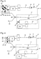
- FIG. 1 shows a schematic and simplified representation of a passively mode-locked ultrashort pulse fiber laser 2 with a resonator in regardsförmiger configuration.
- This type or this configuration of a fiber laser is often referred to as engl .: "figure of eight arrangement”.
- the resonator of the ultrashort pulse fiber laser 2 comprises a main ring 4 and a secondary ring 6 configured as a nonlinear Sagnac interferometer or Sagnac loop.
- the main ring 4 and the secondary ring 6 are coupled to one another via an optical coupler 8.
- An entering via the coupler 8 in the secondary ring 6 laser pulse is split into two partial pulses, with a first partial pulse, for example, in the clockwise direction and the second partial pulse propagates counterclockwise in the secondary ring.
- the two partial pulses meet again at the coupler 8 and interfere with each other.
- the efficiency of the decoupling is adjustable via the interference between the two sub-pulses.
- an active fiber section 10 in which the material of the optical fiber as laser active medium is formed. After passing through the signal through the laser amplifier, the signal at the output has increased power.
- the fiber material of the active fiber section 10 is doped. Suitable doping elements are rare earths, in particular ytterbium (Yb), erbium (Er), neodymium (Nd), thulium (Tm), holmium (Ho) or praseodymium (Pr). The choice of the appropriate doping element depends on the desired fundamental wavelength of the ultrashort pulse fiber laser 2.
- a wavelength multiplexer 12 is further integrated in each case.
- the wavelength multiplexers 12 each serve for coupling pumping light into the active fiber section 10.
- a pumped light source 14 is coupled to the wavelength multiplexers 12 in each case.
- the pump light source 14 is, for example, a laser diode source or another suitable pump light source.
- an optical isolator 16 is further integrated, which ensures that in the main ring 4, the indicated with an arrow propagation direction P of the light pulses is maintained.
- an optical circulator is provided, wherein the associated embodiments will be discussed later.
- a passive optical fiber 18 is further integrated.
- the laser pulses generated in the ultrashort pulse fiber laser 2 are coupled out at an output 20, which is coupled to the main ring 4 via an output coupler 22.
- an active fiber portion 10 in both the main ring 4 and in the side ring 6. Accordingly, it is in the secondary ring 6, which is designed as a nonlinear Sagnac interferometer to a so-called NALM (English: nonlinear amplifying loop mirror). According to further embodiments not shown, there is an active fiber section 10 and correspondingly also the associated wavelength multiplexer 12 and the associated pumping light source 14 only in one of the two fiber rings, ie either in the main ring 4 or in the secondary ring 6.
- the optical fibers from which the ultrashort pulse fiber laser 2 are all polarization-maintaining or polarizing fibers, in particular polarization-preserving single-mode optical fibers.
- the fiber connection between the pumping light source 14 and the wavelength division multiplexer 12 may be non-polarization maintaining or polarization maintaining.
- the optical fibers used are considered if they have a polarization-preserving effect with respect to the laser signal of the ultrashort pulse fiber laser 2.
- the ultrashort pulse fiber laser 2 operates, for example, at a repetition frequency of 20 MHz and a mean laser wavelength in the range between 1000 nm and 1100 nm.
- the ultrashort pulse fiber laser 2 has a dispersion compensation unit 24. This is arranged in the resonator of the ultrashort pulse fiber laser 2, or integrated in the resonator.
- the dispersion compensation unit 24 comprises a dispersion compensation element 26.
- a first polarization adjustment element 28 is provided, which is provided for adapting a polarization state of laser pulses propagating in the fiber to the optical dispersion compensation element 26.
- the polarization adjustment element 28 is arranged in the propagation direction P in front of the dispersion compensation element 24, since the dispersion compensation element 24 has polarization-independent properties. According to the invention, the polarization adjustment element is arranged after the dispersion compensation element. In the more general case, two polarization adjustment modules are provided, before and after the dispersion compensation element 24. This applies to all embodiments.
- FIG. 2 shows another ultrashort pulse fiber laser 2. Elements provided with identical reference symbols of this ultrashort pulse fiber laser 2 are identical to those elements of the already associated with FIG. 1 explained ultrashort pulse fiber laser 2 designed. For this reason, repeated explanations are omitted.
- the dispersion compensation unit 24 includes as dispersion compensation element 26 a first chirped mirror 30 and a second chirped mirror 32.
- the first and second chirped mirrors 30, 32 are preferably arranged plane-parallel to one another.
- a first polarization adjustment element 28 is provided for adjusting the polarization states in the fibers and the dispersion compensation element 26.
- the first polarization adjustment element 28 is arranged between a first end 34 of the optical fiber and the dispersion compensation element 26, according to the illustrated embodiment of the arrangement of the two plane-parallel oriented chirped mirrors 30, 32nd
- the polarization adjustment element 28 is arranged in the propagation direction P in front of the dispersion compensation element 24, since the dispersion compensation element 24 has polarization-independent properties. Again, an arrangement is provided behind or on both sides of the dispersion compensation element 24.
- the chirped mirrors 30, 32 are variable Bragg structure dielectric mirrors. They are advantageously stable and inexpensive and are thus available as elements for dispersion compensation of the propagating laser pulses.
- Dielectric mirrors with a variable Bragg structure are multilayer systems, in which layers with very different optical refractive indices are alternately arranged one above the other. By varying the bilayer thickness, i. the sum of the layer thickness of the two different materials, it is achieved that portions of the laser pulse with different wavelengths are reflected at different depths of the layer package. In this way, a compensation of the dispersion takes place.
- silica / hafnium oxide is suitable.
- the first and second chirped mirrors 30, 32 are in particular highly dispersive chirped mirrors 30, 32.
- a highly dispersive chirped mirror is understood to mean such a mirror which is adapted to carry a group delay dispersion dispersion) in the absolute amount of at least 1,000 fs 2 . It is also possible to replace one or both chirped mirrors 30, 32 with a regular, ie non-dispersive, mirror.
- FIG. 3 shows another ultrashort pulse fiber laser 2. Apart from the dispersion compensation unit 24, this is identical to that in the FIG. 1 and 2 constructed ultrashort pulse fiber lasers 2 constructed. For this reason, a renewed presentation of the known components, which are denoted by identical reference numerals, is dispensed with.
- the dispersion compensation unit 24 includes as dispersion compensation element 26 according to the illustrated embodiment, a first optical grating 36 and a second optical grating 38.
- the first and the second optical grating 36, 38 are preferably arranged plane-parallel to each other.
- At the input of the dispersion compensation unit 24 there is also a first polarization adjustment element 28. This is arranged between the first end 34 of the optical fiber and the dispersion compensation element 26.
- the laser pulse exiting at the first end 34 is adjusted in polarization by the first polarization adjustment element 28 to the dispersion compensation element 26, in the illustrated case to the first and second optical grids 36, 38. After the laser pulse has passed through the first polarization adjustment element 28, it encounters the second optical grating 38.
- the second optical grating 38 causes a spectral fanning of the laser pulse, represented by the widened beam 42. After subsequent reflection at the first optical grating 36, the widened one strikes Beam 42 to a reversing mirror 44, from which it is reflected back.
- a reversing mirror 44 a reversing prism or a tilted mirror is provided.
- dispersion compensation occurs.
- the thus dispersion compensated Laser pulse once again reflected at the second optical grating 38, is reflected by the mirror 40 towards a second end 46 of the optical fiber.
- the laser pulse passes through a second polarization adjustment element 48. This is located at the output of the dispersion compensation unit 24, between the second end 46 of the optical fiber and the dispersion compensation element 28.
- the optical fibers used to construct the ultrashort pulse fiber laser 2 are polarization-maintaining or polarizing optical fibers, so that the laser pulses in the resonator of the ultrashort pulse fiber laser 2 propagate as linearly polarized pulses.
- the first and the second polarization adjustment elements 28, 48 serve to adapt the polarization of, for example, linearly polarized laser pulses propagating in the resonator to the polarization type or direction of the dispersion compensation element 26.
- the second polarization adjustment element 48 serves to reconstitute the polarization, for example the polarization plane, of the polarization adaptation element the dispersion compensation element 26 abandoned laser pulse to the polarization type or plane in which the laser pulses within the resonator, ie in the optical fiber, propagate. If the dispersion compensation element 26 is polarization-independent, one or both of the polarization adjustment elements 28 or 48 may be dispensed with.
- FIG. 4 shows another ultrashort pulse fiber laser 2, the identical to the in FIG. 1 schematically and simplified illustrated ultrashort pulse fiber laser 2 is constructed.
- the passive optical fiber 18 is a highly non-linear passive polarization-maintaining or polarizing optical fiber 19.
- a fiber having a fiber nonlinearity factor ⁇ ⁇ 0 / c0 n2 / Aeff, greater than three, in particular greater than five, more particularly greater than seven, in particular greater than eight, and further particularly greater than ten and, in particular, greater than 13. All values in 1 / (km x W.)
- this highly non-linear optical fiber is polarization-preserving.
- ⁇ 0 is the angular frequency of the laser light c0, the speed of light in the space
- the ultrashort pulse fiber laser 2 Decisive for the functionality of the ultrashort pulse fiber laser 2 is the product of ⁇ * L, where L is the length of the passive optical fiber 18. Compared to conventional nonlinear optical fibers whose value ⁇ is between one and five, the use of a highly nonlinear passive optical fiber 18 results in a shortening of the required fiber length.
- the ultrashort pulse fiber laser provides a pulse repetition rate of 20 MHz and more instead of the otherwise possible repetition frequency in the range of 10 MHz. In addition, due to the lower pulse repetition rate, the noise properties of the laser are lower.
- FIG. 5 shows a dispersion compensation unit 24, which is integrated in an ultrashort pulse fiber laser 2 according to a further embodiment.
- the dispersion compensation unit 24 shown schematically and simplified comprises as dispersion compensation element 26 a volume Bragg grating.
- a laser pulse emerging from the optical fiber at the first end 34 first passes through the beam splitter 50 and is deflected in the direction of the volume Bragg grating. Previously, the laser pulse passes through a ⁇ / 4 plate 54 before it passes through again after reflection on the volume Bragg grating 52.
- ⁇ / 4 plate thus simultaneously fulfills the function of the first and second polarization adjustment elements 28, 48.
- the linearly polarized laser pulse is converted by the ⁇ / 4 plate 54 into a circularly polarized laser pulse, from which volume Bragg gratings 52 are reflected the dispersion of the laser pulse is compensated.
- the circularly polarized laser pulse from the ⁇ / 4 plate 54 is again converted into linearly polarized light and passes through the beam splitter 50 in the direction of the second end 46 of the optical fiber.
- the ultrashort pulse fiber laser 2 comprises an external pulse compressor 56.
- the in Fig. 1 VI section of the ultrashort pulse fiber laser 2 by the in FIG. 6 replaced configuration shown.
- the laser pulse leaving the output 20 enters the external pulse compressor 56 and leaves it at its output.
- the external pulse compressor 56 is preferably constructed similar to the dispersion compensation unit 24. This applies to all embodiments.
- FIG. 7 shows a further ultrashort pulse fiber laser 2 in a simplified schematic representation.
- the ultrashort pulse fiber laser 2 is similar to that in FIG. 1 constructed ultrashort pulse fiber laser 2 constructed. Instead of the in FIG. 1
- the optical isolator shown in FIG. 7 the structure shown has an optical circulator 58, a delay fiber portion 60 coupled thereto, and a return mirror 62.
- the optical circulator 58 has first to third ports.
- the circulator 58 is integrated into the main ring 4 such that laser pulses propagating in the main ring 4 in the propagation direction P are coupled into the circulator 58 at the first connection and forwarded by the circulator 58 to the second connection.
- the delay fiber section 60 is coupled to this second terminal of the circulator 58.
- the delay fiber section 60 also forms part of the main ring 4.
- the dispersion compensation unit 24 is also located at this end. It is designed as mentioned in the aforementioned embodiments.
- the inversion mirror 62 reflects laser pulses that have passed through the delay fiber section 60 back into the delay fiber section 60 to provide a dual pass configuration becomes. As a result, the delay fiber section 60 is thus traversed twice - its length is used twice as an optical path.
- both a separate optical element, for example a mirror, and a fiber-based element are provided, for example a fiber Bragg grating. Due to the large optical path length in the main ring 4, the ultrashort pulse fiber laser 2 shown is designed for particularly low pulse repetition rates.
- FIG. 8th shows in a schematic simplified representation of another ultrashort pulse fiber laser 2, which compared to the in FIG. 7 only differs in that the reversing mirror 62 simultaneously serves as a coupling-out mirror for decoupling the generated laser pulses.
- the output coupler 22 see. Fig. 7 .
- FIG. 9 shows another ultrashort pulse fiber laser 2 similar to that in FIG. 4 shown ultrashort pulse fiber laser 2 is configured. Unlike the in FIG. 4 however, the dispersion compensation unit 24 is not located in the main ring 4 but in the secondary ring 6.
- the dispersion compensation unit 24 is arranged directly behind the coupler 8.
- An asymmetrical arrangement is provided in the nonlinear Sagnac loop (minor ring 6).
- the laser pulses coupled in the secondary rings 6 are preferably chirped or stretched.
- the vast majority of the imprinted chirp is compensated by the dispersion compensation unit 24, so that after the passage of the dispersion compensation unit 24 there is a laser pulse with a higher pulse peak power.
- the compressed laser pulse causes comparable nonlinear effects in the high-nonlinear fiber section 19 as would an amplified uncompressed laser pulse.
- FIG. 10 illustrated embodiment which again shows a schematic simplified representation of an ultrashort pulse fiber laser 2, even more consistently exploited.
- a dispersion compensation unit 24a, 24b is provided in each case.
- the laser pulses circulating in the main ring 4 are chirped by the first dispersion compensating unit 24a, which is compensated in the second dispersion compensating unit 24b.
- Due to the increase in pulse peak power occurring in the high-nonlinear fiber section 19, an increased non-linear effect occurs, for example with regard to the self-phase modulation.
- the asymmetrical arrangement of the dispersion compensation unit 24b has the advantage that the accumulated nonlinear phase becomes more different in both directions of circulation. This effect is essential for the function of a non-linear Sagnac interferometer, so that it is possible to completely dispense with the use of a fiber amplifier in the secondary ring 6. This considerably reduces the manufacturing costs of the ultrashort pulse fiber laser 2.
- Fig. 11 shows in a simplified schematic representation of an ultrashort pulse fiber laser 2, the resonator comprises a main ring 4 and designed as a non-linear Sagnac interferometer side ring 6.
- the main ring 4 and the secondary ring 6 are coupled together via an optical coupler 8.
- an active fiber section 10 and a wavelength multiplexer 12, which is used for coupling a pump signal provided by the pumping light source 14.
- a nonlinear optical fiber 19 is integrated in the secondary ring 6.
- the secondary ring 6 forms together with the optical coupler 8 a so-called NALM (English: nonlinear amplifying loop mirror).
- a propagation direction P of the light pulses is shown by way of example.
- an optical isolator 16 is provided, which can alternatively be integrated in the two positions shown in the main ring 4 or as a discrete optical element in a dispersion compensation and decoupling unit 64.
- this includes in Fig. 11
- This embodiment combines such a dispersion compensation and decoupling unit 64.
- This combines the function of the dispersion compensation unit 24 with that of the decoupler 22 (cf. FIGS. 1 to 4 ). Accordingly, the dispersion compensation and decoupling unit 64 provides an output 20 for the laser light generated by the ultrashort pulse fiber laser 2.
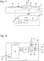
- a dispersion compensation and decoupling unit 64 according to various embodiments is shown in FIGS Figures 12 and 13 shown.
- the laser pulse entering the unit first encounters a first polarization adjustment element 28.
- This comprises a ⁇ / 2 plate 68 which has the function of adjusting the polarization plane of the laser pulse emerging from the fiber in a desired direction.
- the function of the ⁇ / 2 plate 68 corresponds to a rotation of the input fiber 66 about its own axis.
- the first polarization adjustment element 28 also includes a beam splitter 50 acting as a polarizer, with which a fraction of the incoming laser radiation is deflected in the direction of the output fiber 70.
- a further polarization adjustment element (by way of example a third polarization adaptation element 72) is provided. This is optional.
- the function of the polarization adjustment element 72 corresponds to a rotation of the output fiber 70 about its own axis.
- output fiber 70 may be provided according to another embodiment, not shown, an exit window through which the laser radiation is coupled out.
- the dispersion compensation and decoupling unit 64 comprises an optical isolator 16.
- the optical isolator 16 is optionally arranged inside the dispersion compensation and decoupling unit 64.
- an optical isolator 16 can also be arranged in the propagation direction P in front of or behind this unit 64. In such a case, however, it is then a fiber-based insulator rather than a discrete optical component.
- the optical isolator 16 is thus optionally provided within the dispersion compensation and decoupling unit 64.
- the polarization adaptation element 74 is optional.
- the propagating in the propagation direction P laser pulse then strikes the dispersion compensation element 26, which is designed according to one of the aforementioned embodiments.
- the dispersion compensation element 26 which is designed according to one of the aforementioned embodiments.
- the laser pulse Before the laser pulse enters the output fiber 76 at the output of the dispersion compensation and extraction unit 64, it passes through the second polarization adjustment element 48, which is already known as well as the first polarization adjustment element 28 of the previous embodiments.
- the function of the second polarization adjustment element 48 corresponds to a rotation of the output fiber 76 about its own axis.
- the structure shown has the advantage that it is possible to dispense with the fiber outcoupler 22 as well as with the fiber-integrated insulator 16. Firstly, fewer fiber splice points are needed in the resonator, which simplifies manufacturing, and secondly, less fiber is used in the resonator, making the laser 2 overall more compact and allowing higher pulse repetition rates. Further, less dispersion compensation is required in the dispersion compensation unit 26, which also makes this unit more compact.
- the order of the elements shown can be varied. For example, the order of isolator 16 and dispersion compensation element 26 may be reversed. Also, the beam splitter 50 acting as an output coupler could only be detected at the end of the dispersion compensation and decoupling unit 64 are arranged. As already mentioned, instead of the output fiber 70, a coupling-out window, in particular an optically antireflection-coated glass, can be used (free-beam decoupling).
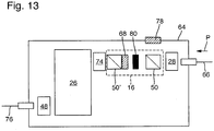
- the dispersion compensation and decoupling unit 64 in FIG Fig. 13 The output coupler is in this embodiment coupled to the optical isolator, has in a sense been "fused".
- "An isolator typically consists of two polarizers or beam splitters 50, 50 ', from The first beam splitter 50 can be used directly for decoupling the laser beam, and includes a Faraday rotator 80 as well as the ones already described Fig. 12 known combination of ⁇ / 2 plate 68 and the second beam splitter 50.
- the function of the ⁇ / 2 plate corresponds to a rotation of the polarizing beam splitter 50 about the optical axis, ie the beam direction at normal incidence on the element.
- the remaining elements provided with identical reference numerals are made Fig. 12 known.
- the function of the polarization matching elements at the input and output of the dispersion compensation and decoupling unit 64 corresponds to a rotation of the input fiber 66 and the output fiber 76, respectively.
- the optical isolator 16 can optionally be located inside or outside the dispersion compensation and decoupling unit 64. Likewise, alternatively, a free-jet decoupling or a decoupling into an output fiber 70 can take place. If corresponding polarization adaptation elements are to be dispensed with, then the input or output fiber 66, 76 would have to be fixed correspondingly in the adjusted position in or on the dispersion compensation and decoupling unit 64. This is also provided according to further embodiments.
Claims (13)
- Laser à fibres (2) à impulsions ultra-courtes couplé en mode passif pour générer des impulsions laser ultra-courtes, comprenant un résonateur à configuration en forme de huit, dans lequel le résonateur comprend un anneau principal (4) et un anneau secondaire (6) qui est relié optiquement à l'anneau principal et est conçu comme un interféromètre de Sagnac non linéaire, et dans lequel l'anneau principal (4) et l'anneau secondaire (6) sont composés de fibres optiques maintenant la polarisation, et l'anneau principal (4) et/ou l'anneau secondaire (6) ont une section de fibres (10) conçue en tant que milieu actif laser, le milieu actif laser étant pompé optiquement par une source lumineuse (14) formant pompe reliée extérieurement qui est également comprise, au moins une unité (24) de compensation de dispersion pour compenser une dispersion retard de groupe des impulsions laser ultra courtes étant présente dans le résonateur, laquelle l'unité de compensation de dispersion (24) étant une unité optique séparée et l'unité de compensation de dispersion (24) comprenant au moins un élément de compensation de dispersion (26), et dans laquelle un trajet de rayon libre (25) est prévu à une entrée et/ou à une sortie de l'unité de compensation de dispersion (24) entre une première extrémité (34) et/ou une deuxième extrémité (46) de la fibre optique de l'anneau principal (4) et/ou de l'anneau secondaire (6) et l'élément de compensation de dispersion (26), de sorte que l'élément de compensation de dispersion (26) forme une unité optique séparée de la fibre optique, et dans lequel un élément d'adaptation de polarisation (28, 48) est prévu à une sortie de l'unité de compensation de dispersion (24), l'élément d'adaptation de polarisation (28, 48) étant agencé pour adapter un état de polarisation d'une impulsion laser quittant l'unité de compensation de dispersion (24) à une direction de polarisation de la fibre optique, un filtre de Lyot étant prévu à la sortie de l'unité de compensation de dispersion (24), lequel filtre comprend un polariseur et un analyseur ainsi qu'un cristal biréfringent disposé entre le polariseur et l'analyseur, l'analyseur du filtre de Lyot étant prévu en tant qu'élément (48) d'adaptation de polarisation.
- Laser à fibres (2) à impulsions ultra-courtes selon la revendication 1, dans lequel l'anneau secondaire (6) est constitué d'une section en fibre optique non linéaire (19) et l'unité de compensation de dispersion (24) est agencée dans l'anneau secondaire (6), une section de fibre (10) étant en particulier également prévue dans l'anneau secondaire (6) en tant que milieu actif laser.
- Laser à fibres (2) à impulsions ultra-courtes selon l'une des revendications précédentes, dans lequel l'anneau principal (4) et l'anneau secondaire (6) sont couplés via un coupleur (8), l'unité de compensation de dispersion (24) étant agencée dans l'anneau secondaire (6) de façon directement adjacente au coupleur.
- Laser à fibres (2) à impulsions ultra-courtes selon la revendication 2, dans lequel l'unité de compensation de dispersion (24) et la section formée par la fibre optique non linéaire (19) sont agencées de façon directement adjacente l'une à l'autre, de sorte qu'une impulsion laser se propageant dans l'anneau secondaire (6), qui est passée au travers de l'unité de compensation de dispersion (24) pour compenser sa dispersion à retard de groupe, entre directement après dans la section formée par la fibre optique non linéaire (19), l'anneau secondaire (6) ne comprenant pas de milieu actif laser.
- Laser à fibres (2) à impulsions ultra-courtes selon l'une des revendications précédentes, dans lequel une première unité de compensation de dispersion (24a) est présente dans l'anneau principal (4) et une deuxième unité de compensation de dispersion (24b) est présente dans l'anneau secondaire (6).
- Laser à fibres optique à impulsions ultra-courtes (2) selon la revendication 2 ou la revendication 4, dans lequel la section formée par la fibre optique non linéaire (19) est une section de fibre optique hautement non linéaire, le facteur de non-linéarité de la section de fibre optique hautement non linéaire étant supérieur à trois, en particulier supérieur à cinq, plus particulièrement supérieur à sept, encore plus particulièrement supérieur à sept, encore plus particulièrement supérieur à huit, encore plus particulièrement supérieur à dix, et encore plus particulièrement supérieur à treize, le facteur de non-linéarité de fibre étant considéré comme étant dans l'unité 1 / (W *km).
- Laser à fibres optiques à impulsions ultra-courtes (2) selon l'une des revendications précédentes, dans lequel un circulateur optique (58) avec une première à une troisième connexion est prévu dans l'anneau principal (4), le circulateur (58) étant intégré dans l'anneau principal (4) de sorte que des impulsions laser se propageant dans une direction de propagation (P) sont couplées dans le circulateur (58) au niveau de la première connexion de l'anneau principal (4) et sont transmises par le circulateur (58) vers la deuxième connexion, une section de fibre à retard (60) de l'anneau principal (4) étant couplée à la deuxième connexion, un miroir inverseur (62), adapté pour réfléchir des impulsions laser passant à travers la section de fibre à retard (60), étant prévu à son extrémité éloignée du circulateur (58), pour réfléchir vers la section de fibre à retard (60), et des impulsions laser, qui ont traversé la partie de fibre à retard (60) provenant du miroir inverseur (62), étant couplées dans le circulateur (58) au niveau de la deuxième connexion et passent du circulateur (58) à la troisième connexion de sorte que l'impulsion laser se propage dans la direction de propagation dans l'anneau principal (4).
- Laser à fibres (2) à impulsions ultra-courtes selon la revendication 7, dans lequel le miroir inverseur (62) est configuré simultanément comme miroir de découplage pour découpler les impulsions laser qui se propagent dans le résonateur.
- Laser à fibres (2) à impulsions ultra-courtes selon l'une des revendications précédentes, dans lequel l'unité de compensation de dispersion (24) comprend, en tant qu'élément de compensation de dispersion (26) au moins un des éléments optiques suivants :au moins un miroir chirpé (30, 32), en particulier deux miroirs chirpés (30, 32) disposés de façon parallèle, en plan, l'un à l'autre,au moins un miroir interféromètre de Gires-Tournois (GTI), en particulier deux miroirs interféromètres de Gires-Tournois (GTI) disposés de façon parallèle, en plan, l'un à l'autre,au moins un réseau optique (36, 38), en particulier deux réseaux optiques (36, 38) disposés de façon parallèle, en plan, l'un à l'autre, et un miroir réversible (44),au moins un réseau de Bragg en volume,au moins un prisme,au moins un prisme en réseau,au moins un réseau de Bragg à fibres chirpées.
- Laser à fibres (2) à impulsions ultra-courtes selon la revendication 9, caractérisé en ce que ledit au moins un miroir chirpé (30, 32), en particulier les deux miroirs chirpés (30, 32), sont des miroirs chirpés (30, 32) hautement dispersifs.
- Laser à fibres (2) à impulsions ultra-courtes selon l'une des revendications précédentes, comprenant en outre un compresseur d'impulsions externe (56) présent en dehors du résonateur.
- Laser à fibres (2) à impulsions ultra-courtes selon l'une des revendications précédentes, dans lequel l'unité de compensation de dispersion (24) est conçue comme une unité de compensation de dispersion et de découplage (64) et comprend à cet effet un découpleur, en particulier conçu comme élément optique discret non à base de fibres.
- Laser à fibres (2) à impulsions ultra-courtes selon la revendication 12, caractérisé en ce que le découpleur sert également d'élément d'adaptation de polarisation.
Applications Claiming Priority (1)
| Application Number | Priority Date | Filing Date | Title |
|---|---|---|---|
| DE102015200366.3A DE102015200366A1 (de) | 2015-01-13 | 2015-01-13 | Ultrakurzpulsfaserlaser |
Publications (2)
| Publication Number | Publication Date |
|---|---|
| EP3046191A1 EP3046191A1 (fr) | 2016-07-20 |
| EP3046191B1 true EP3046191B1 (fr) | 2019-04-17 |
Family
ID=55022327
Family Applications (1)
| Application Number | Title | Priority Date | Filing Date |
|---|---|---|---|
| EP15201560.8A Not-in-force EP3046191B1 (fr) | 2015-01-13 | 2015-12-21 | Laser a fibres a impulsions ultracourtes |
Country Status (3)
| Country | Link |
|---|---|
| US (1) | US9735533B2 (fr) |
| EP (1) | EP3046191B1 (fr) |
| DE (1) | DE102015200366A1 (fr) |
Families Citing this family (14)
| Publication number | Priority date | Publication date | Assignee | Title |
|---|---|---|---|---|
| JP6711600B2 (ja) * | 2015-12-09 | 2020-06-17 | キヤノン株式会社 | 光源装置及び情報取得装置 |
| US10424895B2 (en) * | 2017-12-13 | 2019-09-24 | Industrial Technology Research Institute | Mode-locked fiber laser device |
| US10490968B1 (en) | 2018-05-18 | 2019-11-26 | Ofs Fitel, Llc | Self-starting, passively modelocked figure eight fiber laser |
| US10454247B1 (en) | 2018-10-10 | 2019-10-22 | Ii-Vi Delaware, Inc. | Method of forming a fiber Bragg grating in a pre-assembled laser module |
| FR3096792A1 (fr) * | 2019-05-28 | 2020-12-04 | Leosphere | Architectures de Modulateur Acousto-Optique, de dispositif optique et d’amplificateur optique fibré en double passage. |
| CN110987200B (zh) * | 2019-12-17 | 2021-04-20 | 华中科技大学 | 一种阿秒脉冲的测量方法及装置 |
| RU2747724C1 (ru) * | 2020-07-23 | 2021-05-13 | Общество С Ограниченной Ответственностью "Научно-Техническое Объединение "Ирэ-Полюс" | Способ устойчивой автогенерации ультракоротких лазерных импульсов в поддерживающем состояние поляризации волоконном кольцевом резонаторе и лазер на его основе |
| CA3167130A1 (fr) * | 2020-08-25 | 2022-03-03 | Alaa Al-Kadry | Laser figure en 8 |
| DE102020216434A1 (de) * | 2020-12-21 | 2022-06-23 | Trumpf Laser Gmbh | Passiv modengekoppelter Faseroszillator und Lasereinrichtung mit einem solchen Faseroszillator |
| DE102020216433A1 (de) * | 2020-12-21 | 2022-06-23 | Trumpf Laser Gmbh | Passiv modengekoppelter Faseroszillator und Lasereinrichtung mit einem solchen Faseroszillator |
| DE102021127336A1 (de) | 2021-10-21 | 2023-04-27 | Trumpf Laser Gmbh | Laservorrichtung und Verfahren zum Formen eines Laserpulses |
| DE102022109548A1 (de) * | 2022-04-20 | 2023-10-26 | Trumpf Laser Gmbh | Passiv modengekoppelter Faseroszillator, Lasereinrichtung und nichtlineares CPA-Verstärkungssystem mit einem solchen Faseroszillator |
| CN115133389B (zh) * | 2022-06-28 | 2023-08-04 | 广东大湾区空天信息研究院 | 一种基于非线性放大环形镜的固体激光器 |
| CN116417890B (zh) * | 2023-06-06 | 2023-08-22 | 武汉中科锐择光电科技有限公司 | 基于偏振循环置换光纤被动谐振腔产生超短脉冲的装置 |
Family Cites Families (9)
| Publication number | Priority date | Publication date | Assignee | Title |
|---|---|---|---|---|
| KR0149127B1 (ko) * | 1995-10-31 | 1998-12-01 | 양승택 | 수동과 능동의 혼합형으로 모드로킹 된 레이저 구도 |
| US20060171426A1 (en) * | 2005-02-02 | 2006-08-03 | Andrei Starodoumov | Fiber-laser with intracavity polarization maintaining coupler providing plane polarized output |
| US20080025348A1 (en) * | 2006-07-28 | 2008-01-31 | Kuksenkov Dmitri Vladislavovic | High energy, ultrashort pulse ring fiber laser having a linear dispersion compensator with chirped Bragg gratings |
| US7817684B2 (en) | 2006-11-16 | 2010-10-19 | Ofs Fitel Llc | Passively modelocked figure eight fiber laser |
| US20090003391A1 (en) * | 2007-06-28 | 2009-01-01 | Shenping Li | Low-repetition-rate ring-cavity passively mode-locked fiber laser |
| US7940816B2 (en) * | 2008-09-05 | 2011-05-10 | Ofs Fitel Llc | Figure eight fiber laser for ultrashort pulse generation |
| WO2010056920A1 (fr) * | 2008-11-12 | 2010-05-20 | Cornell University | Oscillateur à fluctuations géantes de longueur d'onde pour une utilisation dans un système d'amplification d'impulsions à fibre |
| EP2846421A1 (fr) * | 2013-09-06 | 2015-03-11 | Menlo Systems GmbH | Laser à miroir à boucle optique non linéaire |
| WO2015059310A1 (fr) * | 2013-10-25 | 2015-04-30 | Atla Lasers As | Sous-système optique à base de graphène |
-
2015
- 2015-01-13 DE DE102015200366.3A patent/DE102015200366A1/de not_active Ceased
- 2015-12-21 EP EP15201560.8A patent/EP3046191B1/fr not_active Not-in-force
-
2016
- 2016-01-12 US US14/993,602 patent/US9735533B2/en not_active Expired - Fee Related
Non-Patent Citations (1)
| Title |
|---|
| None * |
Also Published As
| Publication number | Publication date |
|---|---|
| US9735533B2 (en) | 2017-08-15 |
| EP3046191A1 (fr) | 2016-07-20 |
| US20160204565A1 (en) | 2016-07-14 |
| DE102015200366A1 (de) | 2016-07-14 |
Similar Documents
| Publication | Publication Date | Title |
|---|---|---|
| EP3046191B1 (fr) | Laser a fibres a impulsions ultracourtes | |
| DE112014005158B4 (de) | Kompakte faserbasierte Kurzpuls-Laserquellen | |
| DE112004002187B4 (de) | Gepulste Laserquellen | |
| EP2147488B1 (fr) | Laser accordable | |
| DE112005000710T5 (de) | Modulares faserbasiertes Chirped-Puls-Verstärkersystem | |
| DE4445244B4 (de) | Gegenüber Umwelteinflüssen stabile passiv moden-verkoppelte Faserlaser-Impulsquelle | |
| EP1929594B1 (fr) | Laser a fibre | |
| EP2478599B1 (fr) | Source lumineuse accordable en longueur d'onde | |
| DE112012000796T5 (de) | Kompakte kohärente Lichtquellen mit hoher Helligkeit für das mittlere und ferne Infrarot | |
| DE19510432A1 (de) | Verfahren und Gerät zur Steuerung der Laser-Emissionswellenlänge unter Ausnutzung nichtlinearer Effekte | |
| DE19828154A1 (de) | Auf Multimodefasern basierende Einzelmodenverstärker und -kompressoren | |
| EP3041093B1 (fr) | Système de résonateur optique et procédé de réglage d'un temps de cycle dans un résonateur | |
| EP2478400B1 (fr) | Filtres de modes transversaux pour guide d'onde | |
| WO2022135910A1 (fr) | Oscillateur à fibre à verrouillage de mode passif, et dispositif laser comprenant un oscillateur à fibre de ce type | |
| WO2015114165A1 (fr) | Ensemble optique à division de faisceau | |
| DE102007057856B4 (de) | Faserlaser mit ringförmigem Resonator | |
| DE102016118391B4 (de) | Kurzpulslasersystem | |
| WO1997014226A2 (fr) | Circuiterie servant a compenser la dispersion dans des systemes optiques de transmission au moyen de reseaux de bragg a compression d'impulsions | |
| WO2009132375A1 (fr) | Dispositif d'amplification optique d'impulsions lumineuses | |
| DE102021127336A1 (de) | Laservorrichtung und Verfahren zum Formen eines Laserpulses | |
| DE10261883B4 (de) | Gechirptes Faser-Bragg-Gitter, Lasersystem und Verfahren zur Dispersionskorrektur | |
| DE102014117555B4 (de) | Passiv modengekoppelter faseroptischer Lasergenerator | |
| DE102020209687A1 (de) | Lasersystem zur nichtlinearen Pulskompression und Gitter-Kompressor | |
| DE102022109548A1 (de) | Passiv modengekoppelter Faseroszillator, Lasereinrichtung und nichtlineares CPA-Verstärkungssystem mit einem solchen Faseroszillator | |
| WO2024013094A1 (fr) | Oscillateur à fibre à verrouillage de mode passif, dispositif laser et système d'amplification cpa non linéaire comprenant un tel oscillateur à fibre |
Legal Events
| Date | Code | Title | Description |
|---|---|---|---|
| PUAI | Public reference made under article 153(3) epc to a published international application that has entered the european phase |
Free format text: ORIGINAL CODE: 0009012 |
|
| AK | Designated contracting states |
Kind code of ref document: A1 Designated state(s): AL AT BE BG CH CY CZ DE DK EE ES FI FR GB GR HR HU IE IS IT LI LT LU LV MC MK MT NL NO PL PT RO RS SE SI SK SM TR |
|
| AX | Request for extension of the european patent |
Extension state: BA ME |
|
| 17P | Request for examination filed |
Effective date: 20160929 |
|
| RBV | Designated contracting states (corrected) |
Designated state(s): AL AT BE BG CH CY CZ DE DK EE ES FI FR GB GR HR HU IE IS IT LI LT LU LV MC MK MT NL NO PL PT RO RS SE SI SK SM TR |
|
| STAA | Information on the status of an ep patent application or granted ep patent |
Free format text: STATUS: EXAMINATION IS IN PROGRESS |
|
| 17Q | First examination report despatched |
Effective date: 20170104 |
|
| RAP1 | Party data changed (applicant data changed or rights of an application transferred) |
Owner name: DEUTSCHES ELEKTRONEN-SYNCHROTRON DESY |
|
| RIC1 | Information provided on ipc code assigned before grant |
Ipc: H01S 3/098 20060101ALI20181129BHEP Ipc: H01S 3/106 20060101ALN20181129BHEP Ipc: H01S 3/067 20060101AFI20181129BHEP Ipc: H01S 3/10 20060101ALN20181129BHEP Ipc: H01S 3/082 20060101ALI20181129BHEP |
|
| GRAP | Despatch of communication of intention to grant a patent |
Free format text: ORIGINAL CODE: EPIDOSNIGR1 |
|
| STAA | Information on the status of an ep patent application or granted ep patent |
Free format text: STATUS: GRANT OF PATENT IS INTENDED |
|
| INTG | Intention to grant announced |
Effective date: 20190109 |
|
| GRAS | Grant fee paid |
Free format text: ORIGINAL CODE: EPIDOSNIGR3 |
|
| GRAA | (expected) grant |
Free format text: ORIGINAL CODE: 0009210 |
|
| STAA | Information on the status of an ep patent application or granted ep patent |
Free format text: STATUS: THE PATENT HAS BEEN GRANTED |
|
| AK | Designated contracting states |
Kind code of ref document: B1 Designated state(s): AL AT BE BG CH CY CZ DE DK EE ES FI FR GB GR HR HU IE IS IT LI LT LU LV MC MK MT NL NO PL PT RO RS SE SI SK SM TR |
|
| REG | Reference to a national code |
Ref country code: GB Ref legal event code: FG4D Free format text: NOT ENGLISH |
|
| REG | Reference to a national code |
Ref country code: CH Ref legal event code: EP |
|
| REG | Reference to a national code |
Ref country code: DE Ref legal event code: R096 Ref document number: 502015008715 Country of ref document: DE |
|
| REG | Reference to a national code |
Ref country code: AT Ref legal event code: REF Ref document number: 1122600 Country of ref document: AT Kind code of ref document: T Effective date: 20190515 Ref country code: IE Ref legal event code: FG4D Free format text: LANGUAGE OF EP DOCUMENT: GERMAN |
|
| REG | Reference to a national code |
Ref country code: CH Ref legal event code: NV Representative=s name: ISLER AND PEDRAZZINI AG, CH |
|
| REG | Reference to a national code |
Ref country code: NL Ref legal event code: MP Effective date: 20190417 |
|
| REG | Reference to a national code |
Ref country code: LT Ref legal event code: MG4D |
|
| PG25 | Lapsed in a contracting state [announced via postgrant information from national office to epo] |
Ref country code: NL Free format text: LAPSE BECAUSE OF FAILURE TO SUBMIT A TRANSLATION OF THE DESCRIPTION OR TO PAY THE FEE WITHIN THE PRESCRIBED TIME-LIMIT Effective date: 20190417 |
|
| PG25 | Lapsed in a contracting state [announced via postgrant information from national office to epo] |
Ref country code: NO Free format text: LAPSE BECAUSE OF FAILURE TO SUBMIT A TRANSLATION OF THE DESCRIPTION OR TO PAY THE FEE WITHIN THE PRESCRIBED TIME-LIMIT Effective date: 20190717 Ref country code: AL Free format text: LAPSE BECAUSE OF FAILURE TO SUBMIT A TRANSLATION OF THE DESCRIPTION OR TO PAY THE FEE WITHIN THE PRESCRIBED TIME-LIMIT Effective date: 20190417 Ref country code: FI Free format text: LAPSE BECAUSE OF FAILURE TO SUBMIT A TRANSLATION OF THE DESCRIPTION OR TO PAY THE FEE WITHIN THE PRESCRIBED TIME-LIMIT Effective date: 20190417 Ref country code: HR Free format text: LAPSE BECAUSE OF FAILURE TO SUBMIT A TRANSLATION OF THE DESCRIPTION OR TO PAY THE FEE WITHIN THE PRESCRIBED TIME-LIMIT Effective date: 20190417 Ref country code: SE Free format text: LAPSE BECAUSE OF FAILURE TO SUBMIT A TRANSLATION OF THE DESCRIPTION OR TO PAY THE FEE WITHIN THE PRESCRIBED TIME-LIMIT Effective date: 20190417 Ref country code: PT Free format text: LAPSE BECAUSE OF FAILURE TO SUBMIT A TRANSLATION OF THE DESCRIPTION OR TO PAY THE FEE WITHIN THE PRESCRIBED TIME-LIMIT Effective date: 20190817 Ref country code: ES Free format text: LAPSE BECAUSE OF FAILURE TO SUBMIT A TRANSLATION OF THE DESCRIPTION OR TO PAY THE FEE WITHIN THE PRESCRIBED TIME-LIMIT Effective date: 20190417 Ref country code: LT Free format text: LAPSE BECAUSE OF FAILURE TO SUBMIT A TRANSLATION OF THE DESCRIPTION OR TO PAY THE FEE WITHIN THE PRESCRIBED TIME-LIMIT Effective date: 20190417 |
|
| PG25 | Lapsed in a contracting state [announced via postgrant information from national office to epo] |
Ref country code: GR Free format text: LAPSE BECAUSE OF FAILURE TO SUBMIT A TRANSLATION OF THE DESCRIPTION OR TO PAY THE FEE WITHIN THE PRESCRIBED TIME-LIMIT Effective date: 20190718 Ref country code: BG Free format text: LAPSE BECAUSE OF FAILURE TO SUBMIT A TRANSLATION OF THE DESCRIPTION OR TO PAY THE FEE WITHIN THE PRESCRIBED TIME-LIMIT Effective date: 20190717 Ref country code: PL Free format text: LAPSE BECAUSE OF FAILURE TO SUBMIT A TRANSLATION OF THE DESCRIPTION OR TO PAY THE FEE WITHIN THE PRESCRIBED TIME-LIMIT Effective date: 20190417 Ref country code: RS Free format text: LAPSE BECAUSE OF FAILURE TO SUBMIT A TRANSLATION OF THE DESCRIPTION OR TO PAY THE FEE WITHIN THE PRESCRIBED TIME-LIMIT Effective date: 20190417 Ref country code: LV Free format text: LAPSE BECAUSE OF FAILURE TO SUBMIT A TRANSLATION OF THE DESCRIPTION OR TO PAY THE FEE WITHIN THE PRESCRIBED TIME-LIMIT Effective date: 20190417 |
|
| PG25 | Lapsed in a contracting state [announced via postgrant information from national office to epo] |
Ref country code: IS Free format text: LAPSE BECAUSE OF FAILURE TO SUBMIT A TRANSLATION OF THE DESCRIPTION OR TO PAY THE FEE WITHIN THE PRESCRIBED TIME-LIMIT Effective date: 20190817 |
|
| REG | Reference to a national code |
Ref country code: DE Ref legal event code: R097 Ref document number: 502015008715 Country of ref document: DE |
|
| PG25 | Lapsed in a contracting state [announced via postgrant information from national office to epo] |
Ref country code: CZ Free format text: LAPSE BECAUSE OF FAILURE TO SUBMIT A TRANSLATION OF THE DESCRIPTION OR TO PAY THE FEE WITHIN THE PRESCRIBED TIME-LIMIT Effective date: 20190417 Ref country code: RO Free format text: LAPSE BECAUSE OF FAILURE TO SUBMIT A TRANSLATION OF THE DESCRIPTION OR TO PAY THE FEE WITHIN THE PRESCRIBED TIME-LIMIT Effective date: 20190417 Ref country code: EE Free format text: LAPSE BECAUSE OF FAILURE TO SUBMIT A TRANSLATION OF THE DESCRIPTION OR TO PAY THE FEE WITHIN THE PRESCRIBED TIME-LIMIT Effective date: 20190417 Ref country code: DK Free format text: LAPSE BECAUSE OF FAILURE TO SUBMIT A TRANSLATION OF THE DESCRIPTION OR TO PAY THE FEE WITHIN THE PRESCRIBED TIME-LIMIT Effective date: 20190417 Ref country code: SK Free format text: LAPSE BECAUSE OF FAILURE TO SUBMIT A TRANSLATION OF THE DESCRIPTION OR TO PAY THE FEE WITHIN THE PRESCRIBED TIME-LIMIT Effective date: 20190417 |
|
| PLBE | No opposition filed within time limit |
Free format text: ORIGINAL CODE: 0009261 |
|
| STAA | Information on the status of an ep patent application or granted ep patent |
Free format text: STATUS: NO OPPOSITION FILED WITHIN TIME LIMIT |
|
| PG25 | Lapsed in a contracting state [announced via postgrant information from national office to epo] |
Ref country code: SM Free format text: LAPSE BECAUSE OF FAILURE TO SUBMIT A TRANSLATION OF THE DESCRIPTION OR TO PAY THE FEE WITHIN THE PRESCRIBED TIME-LIMIT Effective date: 20190417 Ref country code: IT Free format text: LAPSE BECAUSE OF FAILURE TO SUBMIT A TRANSLATION OF THE DESCRIPTION OR TO PAY THE FEE WITHIN THE PRESCRIBED TIME-LIMIT Effective date: 20190417 |
|
| 26N | No opposition filed |
Effective date: 20200120 |
|
| PG25 | Lapsed in a contracting state [announced via postgrant information from national office to epo] |
Ref country code: TR Free format text: LAPSE BECAUSE OF FAILURE TO SUBMIT A TRANSLATION OF THE DESCRIPTION OR TO PAY THE FEE WITHIN THE PRESCRIBED TIME-LIMIT Effective date: 20190417 |
|
| PG25 | Lapsed in a contracting state [announced via postgrant information from national office to epo] |
Ref country code: SI Free format text: LAPSE BECAUSE OF FAILURE TO SUBMIT A TRANSLATION OF THE DESCRIPTION OR TO PAY THE FEE WITHIN THE PRESCRIBED TIME-LIMIT Effective date: 20190417 |
|
| REG | Reference to a national code |
Ref country code: BE Ref legal event code: MM Effective date: 20191231 |
|
| PG25 | Lapsed in a contracting state [announced via postgrant information from national office to epo] |
Ref country code: MC Free format text: LAPSE BECAUSE OF FAILURE TO SUBMIT A TRANSLATION OF THE DESCRIPTION OR TO PAY THE FEE WITHIN THE PRESCRIBED TIME-LIMIT Effective date: 20190417 |
|
| PG25 | Lapsed in a contracting state [announced via postgrant information from national office to epo] |
Ref country code: LU Free format text: LAPSE BECAUSE OF NON-PAYMENT OF DUE FEES Effective date: 20191221 Ref country code: IE Free format text: LAPSE BECAUSE OF NON-PAYMENT OF DUE FEES Effective date: 20191221 |
|
| PG25 | Lapsed in a contracting state [announced via postgrant information from national office to epo] |
Ref country code: BE Free format text: LAPSE BECAUSE OF NON-PAYMENT OF DUE FEES Effective date: 20191231 |
|
| PGFP | Annual fee paid to national office [announced via postgrant information from national office to epo] |
Ref country code: FR Payment date: 20201217 Year of fee payment: 6 Ref country code: CH Payment date: 20201222 Year of fee payment: 6 Ref country code: GB Payment date: 20201222 Year of fee payment: 6 Ref country code: DE Payment date: 20201216 Year of fee payment: 6 |
|
| PG25 | Lapsed in a contracting state [announced via postgrant information from national office to epo] |
Ref country code: CY Free format text: LAPSE BECAUSE OF FAILURE TO SUBMIT A TRANSLATION OF THE DESCRIPTION OR TO PAY THE FEE WITHIN THE PRESCRIBED TIME-LIMIT Effective date: 20190417 |
|
| PG25 | Lapsed in a contracting state [announced via postgrant information from national office to epo] |
Ref country code: MT Free format text: LAPSE BECAUSE OF FAILURE TO SUBMIT A TRANSLATION OF THE DESCRIPTION OR TO PAY THE FEE WITHIN THE PRESCRIBED TIME-LIMIT Effective date: 20190417 Ref country code: HU Free format text: LAPSE BECAUSE OF FAILURE TO SUBMIT A TRANSLATION OF THE DESCRIPTION OR TO PAY THE FEE WITHIN THE PRESCRIBED TIME-LIMIT; INVALID AB INITIO Effective date: 20151221 |
|
| REG | Reference to a national code |
Ref country code: AT Ref legal event code: MM01 Ref document number: 1122600 Country of ref document: AT Kind code of ref document: T Effective date: 20201221 |
|
| PG25 | Lapsed in a contracting state [announced via postgrant information from national office to epo] |
Ref country code: AT Free format text: LAPSE BECAUSE OF NON-PAYMENT OF DUE FEES Effective date: 20201221 |
|
| PG25 | Lapsed in a contracting state [announced via postgrant information from national office to epo] |
Ref country code: MK Free format text: LAPSE BECAUSE OF FAILURE TO SUBMIT A TRANSLATION OF THE DESCRIPTION OR TO PAY THE FEE WITHIN THE PRESCRIBED TIME-LIMIT Effective date: 20190417 |
|
| REG | Reference to a national code |
Ref country code: DE Ref legal event code: R119 Ref document number: 502015008715 Country of ref document: DE |
|
| REG | Reference to a national code |
Ref country code: CH Ref legal event code: PL |
|
| GBPC | Gb: european patent ceased through non-payment of renewal fee |
Effective date: 20211221 |
|
| PG25 | Lapsed in a contracting state [announced via postgrant information from national office to epo] |
Ref country code: GB Free format text: LAPSE BECAUSE OF NON-PAYMENT OF DUE FEES Effective date: 20211221 Ref country code: DE Free format text: LAPSE BECAUSE OF NON-PAYMENT OF DUE FEES Effective date: 20220701 |
|
| PG25 | Lapsed in a contracting state [announced via postgrant information from national office to epo] |
Ref country code: FR Free format text: LAPSE BECAUSE OF NON-PAYMENT OF DUE FEES Effective date: 20211231 |
|
| PG25 | Lapsed in a contracting state [announced via postgrant information from national office to epo] |
Ref country code: LI Free format text: LAPSE BECAUSE OF NON-PAYMENT OF DUE FEES Effective date: 20211231 Ref country code: CH Free format text: LAPSE BECAUSE OF NON-PAYMENT OF DUE FEES Effective date: 20211231 |