EP0798621B1 - Système de communication de données et dispositif de gestion d'informations - Google Patents
Système de communication de données et dispositif de gestion d'informations Download PDFInfo
- Publication number
- EP0798621B1 EP0798621B1 EP97103143A EP97103143A EP0798621B1 EP 0798621 B1 EP0798621 B1 EP 0798621B1 EP 97103143 A EP97103143 A EP 97103143A EP 97103143 A EP97103143 A EP 97103143A EP 0798621 B1 EP0798621 B1 EP 0798621B1
- Authority
- EP
- European Patent Office
- Prior art keywords
- data
- data item
- displayed
- memory
- received
- Prior art date
- Legal status (The legal status is an assumption and is not a legal conclusion. Google has not performed a legal analysis and makes no representation as to the accuracy of the status listed.)
- Expired - Lifetime
Links
Images


Classifications
-
- H—ELECTRICITY
- H04—ELECTRIC COMMUNICATION TECHNIQUE
- H04B—TRANSMISSION
- H04B1/00—Details of transmission systems, not covered by a single one of groups H04B3/00 - H04B13/00; Details of transmission systems not characterised by the medium used for transmission
-
- G—PHYSICS
- G08—SIGNALLING
- G08B—SIGNALLING OR CALLING SYSTEMS; ORDER TELEGRAPHS; ALARM SYSTEMS
- G08B5/00—Visible signalling systems, e.g. personal calling systems, remote indication of seats occupied
- G08B5/22—Visible signalling systems, e.g. personal calling systems, remote indication of seats occupied using electric transmission; using electromagnetic transmission
- G08B5/222—Personal calling arrangements or devices, i.e. paging systems
- G08B5/223—Personal calling arrangements or devices, i.e. paging systems using wireless transmission
- G08B5/224—Paging receivers with visible signalling details
- G08B5/227—Paging receivers with visible signalling details with call or message storage means
Definitions
- the present invention relates to a data transmission system and an information management apparatus having a communication function adapted to the system.
- portable information management apparatuses including electronic notebooks and handheld computers, have been known.
- the portable information management apparatuses are structured such that information of various categories having different attributes each other, such as schedule data indicating the schedule of the user, address-book data consisting of a plurality of personal data including names and telephone numbers, are previously input so as to be displayed when required.
- the pager receiver has the information management function as described above, that is, if the pager receiver is an information management apparatus provided with a paging signal receiving function, a function permitting data, such as schedule data and address-book data, to be transmitted and received is expected to make the pager receiver to be a further convenient apparatus as a communication means.
- the message data, schedule data and address-book data which must be displayed have different attributes because of their different purposes. If data is transmitted or received regardless of the attribute of data, user of the receiving device must determine the attribute of transmitted data to store the same in a corresponding region in a memory.
- US 5,038,284 is directed to a central computer equipped with communications hardware and specially designed software receives transaction data from person transaction stations operated by traders, sends back verification information to the traders, reconciles all trades, informs traders when an error occurs, generates complete records of all transactions, reports price and volume data to quote vendors, provides numerous reports which analyze trading activity to detect potential regulatory violations, creates a complete real-time backup copy of all data, and provides intraday profit, loss, risk, and margin information to exchange and Futures Commission Merchant personnel.
- US 4,473,824 is directed to a price quotation system for conveying quotations of interest to the financial community comprising a transmitter for receiving a plurality of said quotations and broadcasting serial data representing each of said quotations, a handheld, portable receiver for receiving the serially transmitted data, storage means in the handheld receiver for individually storing the serially received data representing each of the quotations, a display on the handheld receiver, and means on the handheld receiver coupled to the storage means and the display means for individually selecting the stored data representing any one of the quotations and displaying it as a selected quotation.
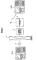
- FIG. 1 is a diagram showing the structure of the wireless paging system using information management apparatuses 1A and 1B according to the present invention as a data transmission terminal and a data receiving terminal.
- the information management apparatus 1 is an electronic notebook having a dial tone output function and a paging signal receiving function.
- a telephone terminal 2 such as a push-phone telephone set, is connected to a center (a central control station) 4 administrated by a paging service.
- a transmission station 5 is connected to the center 4.
- a predetermined call number is, in the form of a dial signal, for example, a DTMF (Dual Tone Multiple-Frequency: dial tone) signal
- a DTMF Dual Tone Multiple-Frequency: dial tone
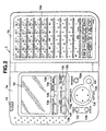
- FIGS. 2 and 3 are diagrams showing the shape of the electronic notebook 1 (1A and 1B).
- FIG. 2 is a front view showing an opened electronic notebook 1 having a shape like a notebook
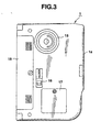
- FIG. 3 is a diagram showing a state where the electronic notebook 1 is closed.
- the electronic notebook 1 has, on the inner surface of the left-hand side thereof in an opened state, a display portion 12 comprising a dot-matrix type liquid crystal display panel, a display-on key 13a, a display-off key 13b, a display switch key 13c, a menu key 13d, a search key 13e, an icon search key 13f, a function key 13g, a secret key 13h, a call number key 13i, an execute key 13k, a cursor key 13l, a the message key 13m and a dial key 13n.
- an IR transmitting/receiver 14, a connector 15 and a pager power supply switch 16 are disposed on the top end of the electronic notebook 1.
- the display-on key 13a is a key for turning on the function of the electronic notebook and, in a case where the function of the electronic notebook has been turned on, for shifting the state of the electronic notebook 1 to a state where data is newly input.
- the display-off key 13b is a key for turning off the function of the electronic notebook 1 to turn off the display.
- the display switch key 13c is a key for switching the display
- the menu key 13d is a key for shifting the mode for displaying a menu of all modes provided for the electronic notebook 1.
- the search key 13e is a key for instructing data search or cancellation of the data search.
- the icon search key 13f is a key for searching data for each icon or cancellation of the searching operation.
- the call number key 13i is a key for displaying data registered in the telephone directory mode, that is, a list of only the call number, the type and name of the owner of the pager receiver from an address-book data memory DB, to be described later.
- the cancel key 13j is a key for canceling the function or the operation, which is being performed, or the "kana-kanji" conversion.
- the execute key 13k is a key for instructing execution of the selected function.
- the cursor key 13l is a key for instructing the movement of the cursor into the upward, downward, rightward and leftward directions, the cursor being displayed in various forms corresponding to the selected states, such as a menu display mode, a file selection display mode, date selection display mode, a character edition display mode and so forth.
- the message key 13m is a key for shifting the state of display of a received message stored in a received message data memory RD, to be described later.
- the dial key 13n is a key for instructing to start transmitting the dial signal indicating the telephone number and data, for example, the DTMF signal.
- the IR transmitting/receiver 14 has a structure such that an infrared light emission portion and an infrared light receiver are formed integrally to directly transmit/receive various data items to and from another electronic notebook 1 having a similar structure.
- a sheet key 13o is disposed on the inner surface of the right-hand side 1b of the electronic notebook 1, the sheet key 13o having a multiplicity of "kana" keys, alphabet keys, numeral keys, symbol keys and various function keys disposed in an overlap manner.
- input and instruction can be performed such that data is input, edited, converted and registered, the calculator function is used and a the message is protected.
- a connector (not shown) is formed in the side surface of the left-hand side 1a of the electronic notebook 1, the connector being, through an electric line, connected to another electronic notebook 1 having a similar structure so as to transmit/receive various data items.
- FIG. 3 is a diagram showing a state where the electronic notebook 1 is closed and the shape of the reverse side of the left-hand side 1a shown in FIG. 2.
- the reverse side of the electronic notebook 1 has a battery cover 15 for accommodating, for example, four size-AAA-batteries serving as a power source for operating the electronic notebook 1, a lock switch 16 for preventing unintentional opening of the battery cover 15, a backup battery cover 17 for accommodating a backup button battery for saving the contents of the memory individually from the batteries accommodated in the battery cover 15, and a loudspeaker unit 18 for outputting the DTMF signal and the like.
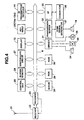
- FIG. 4 shows the structure of a circuit provided in the electronic notebook 1 (1A and 1B).
- Radio waves for calling the electronic notebook 1 are received by an antenna 21 so as to be supplied to the receiver 22.
- the receiver 22 demodulates data received by the antenna 21 into binary or quadruple digital data to transmit the same to a decoder 23.
- the decoder 23 When the decoder 23 has detected power supply, the decoder 23 operate the receiver 22 under control of a control unit 25 connected through a bus line B until a synchronizing signal is received within a predetermined time. When the decoder 23 has detected the synchronizing signal, the decoder 23 intermittently operates the receiver 22 in accordance with a control signal supplied from the control unit 25 which has fetched frame number data stored in an ID-ROM 24.
- the decoder 23 converts the signal demodulated by the receiver 22 into an 8-bit parallel data to transmit it to the control unit 25.
- the decoder 23 transmits, to the control unit 25, vector data and the message data, which are received next.
- the control unit 25 is, through the bus line B, connected to the decoder 23, the ID-ROM 24, the IR transmitting/receiver 14, a key input portion 26, the display portion 12, a deinterleave circuit 27, a buffer memory 28, a ROM 29, a RAM 30, a driver 31, a transmission buffer 32 and an interface (IF) 33.
- the control unit 25 controls the receiving operation of the decoder 23 and the overall operation of the circuit.
- the deinterleave circuit 27 is, under control of the control unit 25, suspends the interleaving process to which received data, that is, received data in a digital value decoded by the decoder 23 is being subjected so as to restore the same to the original code arrangement.
- the buffer memory 28 temporarily stores received data directly supplied from the decoder 23 to supply the same to the deinterleave circuit 27.
- FIG. 5 is a diagram showing an example of a region for various information items stored in the ROM 29, the ROM 29 having regions for a control program CP for the control unit 25, character generator CG for storing pattern data of various characters including, numerals, symbols, alphabets, "hiragana”, “katakana”, “kanji” and icons to be displayed on the display portion 12, #(shift)JIS code table JC for converting "kanji", “katakana”, “hiragana”, capital and small letters of alphabets, symbols and icons into a form as "#OOOO", pager receiver type table PT indicating, with numbers, the types of pager receivers, mode code table MT storing mode name data and the like corresponding to the code of the operation mode, and various transmission code conversion table CT corresponding to the type of the pager receiver.
- character generator CG for storing pattern data of various characters including, numerals, symbols, alphabets, "hiragana”, “katakana”, “kanji” and icons to be displayed on the display portion 12
- FIG. 6 is a diagram showing the contents stored in the pager receiver type table PT in which "kanji display” type pager receivers each of which is capable of displaying "kanji” and the like to correspond to the #JIS code are classified as “1", "free direct” type pager receivers each of which conforms to RCR STD-43 are classified as “2”, "free numerals/kana” type pager receivers are classified as “3” and “numeral display” type pager receivers are classified as "4".
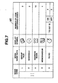
- FIG. 7 is a diagram showing the contents stored in the mode code table MT in which "mode codes”, “mode name data”, “display symbols” and “number of codes for switching the item” corresponding to five modes of ten modes of the electronic notebook function are stored, that is, “group talk” mode, “schedule” mode, “address book” mode, “memorandum” mode and “To Do” mode are stored.
- the mode code is in the form as "][1" if the mode is the group talk mode. That is, symbol “][” is provided for the leading end of the code, the symbols “][” being converted into #JIS code such that symbol "]” is converted into "0147” and symbol “[” is converted into "0146".
- the overall mode code is formed into nine-digit code data.
- the number of codes for switching the item indicates the number of codes for switching the item which is inserted into one transmission data item.
- the code for switching the item is indicated by "[]”.
- FIG. 8 is a diagram showing storage regions of the RAM 30.
- the RAM 30 has storage regions for a received message data memory RD for sequentially storing received message data suspended from the interleave process in the deinterleave circuit 27, a group talk memory GT for storing data, which is transmitted/received between groups and which is used in the "group talk" mode, a schedule data memory SD to be described later, an address-book data memory DB for storing names and telephone numbers of a plurality of persons, the number and the type of the pager receiver of the user and address, a memorandum data memory MD for storing memorandum data and "To Do" data memory TD for storing "To Do" data indicating important event which must be performed.
- a received message data memory RD for sequentially storing received message data suspended from the interleave process in the deinterleave circuit 27, a group talk memory GT for storing data, which is transmitted/received between groups and which is used in the "group talk" mode, a schedule
- FIG. 9 is a diagram showing an example of the contents stored in the schedule data memory SD of the RAM 30 of the electronic notebook 1A arranged to transmit the message data and shown in FIG. 1.
- Schedule data is formed into a set consisting of a first item including date, start time (minute and hour) and end time (minute and hour), a second item including the contents of the schedule, a third item including an icon and a fourth item including alarm set time (minute and hour).
- a plurality of sets of schedule data are given storage addresses, and then stored in accordance with the order of the contents in the first item.
- the driver 31 is connected to a loudspeaker unit 34, a vibrator 35 and an LED 36 so as to selectively operate the connected units in accordance with the determined contents so as to notify receipt of a the message with a buzzer sound, vibrations or flickering of light.
- the transmission buffer 32 sequentially stores digital DTMF signals formed on the basis of transmission data produced by the control unit 25 so as to transmit the same to a D/A converter 37.
- the D/A converter 37 converts the DTMF signal into an analog signal to operate the loudspeaker unit 18 provided on the reverse side of the electronic notebook 1.
- a DTMF signal formed by combining two predetermined audible frequency signals are emitted as a sound.
- the interface 33 is provided to directly transmit/receive data to and from another electronic notebook 1 through the connector 38 disposed on the side surface of the electronic notebook 1 (not shown in FIGS. 2 and 3) and an electric line connected to the other electronic notebook 1.
- schedule data stored by the transmission-side electronic notebook 1A shown in FIG. 1 is selected so as to be transmitted.
- the electronic notebook 1B which has received schedule data through the telephone terminal 2, the public network 3 and the center 4 confirms the contents of schedule data and then stores the same into a predetermined memory region.
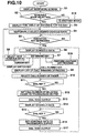
- FIG. 10 is a diagram mainly showing an operation of the control unit 25 when it transmits schedule data in the transmission mode.
- the mode menu screen is displayed on the display portion 12 (step S1).
- the mode menu screen is displayed when the display-on key 13a has been depressed in a state where the power supply is turned off or when the menu key 13d has been depressed.
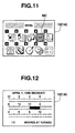
- FIG. 11 is a diagram showing the mode menu screen on the display portion 12 at this time.
- a mode indicated by numeral "1" and an icon in the form of a mail box having an arrow facing the inside portion of the mail box is the "received message display mode" in which the message data stored in the received message data memory RD can be displayed.
- a mode indicated by numeral "2" and an icon in the form of a letter paper having an arrow facing outside from the letter paper is a "the message generation mode" in which the message data, required to be transmitted, can be generated to be adaptable to the type of the receiving-side pager receiver.
- a mode indicated by numeral "3" and an icon in the form of the faces of two persons is a "group talk mode” in which the messages stored in the group talk memory GT and transmitted/received to and from (one or plural) specific persons can be displayed or a new the message, required to be transmitted to a specific person, can be input.
- a mode indicated by numeral "4" and an icon in the form of a clock having a surrounding arrow is a "schedule mode” in which schedule data stored in the schedule data memory SD can be displayed and new schedule data can be registered to the schedule data memory SD.
- a mode indicated by numeral "5" and an icon in the form of a calendar is a "calendar mode" in which a calendar sheet of each month can be displayed.
- a mode indicated by numeral "6" and an icon in the form of a telephone set is an "address book mode" in which address data of plural persons stored in the address-book data memory DB, that is, telephone numbers and addresses can be displayed or new address data can be registered to the address-book data memory DB.
- a mode indicated by numeral "7" and an icon in the form of a memorandum sheet and a pencil is a "memorandum mode" in which memorandum data stored in the memorandum data memory MD can be displayed or new memorandum data can be stored in the memorandum data memory MD.
- a mode indicated by numeral "8" and an icon in the form of the head of a person and an exclamation mark is a ""To Do” mode” in which events stored in the "To Do” data memory TD and which must be performed can be displayed or a new event which must be performed can be registered to the "To Do” data memory TD.
- a mode indicated by numeral “9” and an icon in the form of a clock and a shadow overlapping the clock is a "clock mode” in which the present date or time can be displayed or modified.
- a mode indicated by numeral "10” and symbols of four rules of arithmetic is a "calculator mode” in which a calculation can be performed.
- the "schedule mode” is selected.
- the selection of the "schedule mode” can be performed by operating the cursor key 131 in the state where the mode menu screen is displayed, and then the menu cursor MC is shifted to a position of an icon indicating the "schedule mode", as shown in FIG. 11. Then, the execute key 13k is required to be depressed.
- the control unit 25 determines that a mode selection for displaying schedule data stored in the schedule data memory SD of the RAM 30 has been instructed so that the control unit 25 reads all of schedule data items of the day from the schedule data memory SD and causes a time table corresponding to the set time zone to be displayed on the display portion 12 (step S3).
- FIG. 12 is a diagram showing an example of the display.
- the cursor key 131 is not required to be operated because only one schedule data item is set for the day. If a plurality of schedule data items are set, the cursor key 131 is moved to the right or left to sequentially switch the time zones on the time table which are flickered. Moreover, also data of the leading end of the contents of the schedule to be displayed is switched to the corresponding to the contents.
- step S4 desired schedule date is temporarily selected.
- step S5 whether or not the execute key 13k has been operated is determined. If a determination has been performed that the execute key 13k has been operated, selected schedule data is displayed on the display portion 12 in place of displaying the foregoing time table (step S6).
- FIG. 13 is a diagram showing an example of the above-mentioned state. As shown in FIG. 13, facts that "Movies at Yurakucho” has been set as schedule data for "12:00 PM to 14:00 PM” for "April 1 (Monday), 1996, and alarm has been set to "11:00 AM” are displayed with two bell-shape icons AC.
- step S7 determines which key is operated. If the cursor key 13l has been operated, next schedule data is selected in step S8, and then the operation returns to step S6 so that next schedule data is displayed. If the display switch key 13c has been operated, the operation returns to step S4 so that the original time table is displayed. If the call number key 13i has been operated, call numbers, types and names of owners of pager receivers are read from address data stored in the address-book data memory DB of the RAM 30 to display a list on the display portion 12 (step S9). Then, the cursor key 13l is operated to select a call number of the destined apparatus to which selected schedule data must be transmitted (step S10).
- step S11 If the dial key 13n is operated in the above-mentioned state (step S11), the call number of the selected pager receiver is read from the address-book data memory DB so as to be set to the transmission buffer 32 (step S12) as data to be transmitted. Then, the call number of the pager receiver set to the transmission buffer 32 is supplied to the DTMF signal generating portion 37 so that dial tone corresponding to the call number of the pager receiver is output from the loudspeaker unit 18 (step S13). Note the loudspeaker unit 18 disposed on the reverse side of the electronic notebook 1A must be brought into contact with the transmitter of an arbitrary telephone terminal 2 when the dial key 13n is operated.
- schedule data selected in step S10 is again displayed on the display portion 12 (step S14).
- the paging service center 4 When the paging service center 4 has received the call number of the pager receiver, it outputs a response announcement, for example, "Please input a the message" to the calling-side telephone terminal 2 through the public network 3.
- the owner of the electronic notebook 1A confirms the response announcement from the center 4, and then applying the loudspeaker unit 18 to the transmitter of the telephone terminal 2 to operate the dial key 13n (step S15).
- schedule data which must be transmitted, is schedule shown in FIG. 13
- data which is transmitted from the paging center 4 to the receiving-side electronic notebook 1B through the transmission station 5 is in the form as "][21996040112001400 [] Movies at Yurakucho [] [] 1100".
- data, which must be set to the transmission buffer 32 that is, data required to transmit data to the paging center 4 in the form of a DTMF signal is as follows:
- Leading data "][2" is a mode code indicating schedule also described with reference to FIG. 7.
- Data is set to the transmission buffer 32 as data of 9 (4 digits ⁇ 2 characters + one numeral) digits in accordance with the #JIS code.
- Data of the first item of the schedule data that is, "1996040112001400" indicating date, start time and end time is allowed to remain to be numerals and set to the transmission buffer 32 as numeral data of 12 digits.
- the item switch code "[ ]" is set to the transmission buffer 32 as 8 (4 digits ⁇ 2 characters) digit numeral data in accordance with the #JIS code.
- item switch code "[ ]” is added twice so as to be set to the transmission buffer 32 as numeral data for 16 digits. Then, data "1100" indicating the alarm time in the fourth item is allowed to remain to be four digit numeral data when set to the transmission buffer 32.
- step S17 After data generated from schedule data and required to be transmitted has been set to the transmission buffer 32, data is converted into a DTMF signal by the DTMF signal generating portion 37 in step S17 so as to be output to the loudspeaker unit 18.
- dial tone corresponding to data to be transmitted is output from the loudspeaker unit 18 as sound.
- control unit 25 stores all digits of data stored in the transmission buffer 32 and counts the number of remaining digits of data supplied from the transmission buffer 32 to be output from the loudspeaker unit 18 through the DTMF signal generating portion 37 as sound.
- control unit 25 calculates time required to transmit residual data, specifically, number of seconds in accordance with a . predetermined transmission rate to display the number of seconds on the display portion 12.
- FIG. 14 is a diagram showing an example of display on the display portion 12. Characters as "Dialing is being Performed", an icon of a telephone set which is being dialed by the finger and the residual number of seconds, for example, "five seconds are required", are displayed. Moreover, a guide message for interrupting the transmission is displayed as "To Interrupt, Operate Cancel Key”.
- Display of the residual number of seconds is continuously updated at a predetermined interval, for example, every second to decreases the display count. Then, when the residual number of seconds has been made to be "0", it is determined that all of data items have been transmitted. Thus, for example, characters "Transmission Completed” are displayed on the display portion 12 in place of the display shown in FIG. 14. Thus, the foregoing sequential operations shown in FIG. 10 are temporarily completed. Moreover, in order to transmit schedule data to another apparatus, the process from step S6 is repeatedly performed.
- step S18 If it is determined that a mode except the schedule mode has been selected from the mode menu screen in step S2, a process corresponding to the selected mode is performed as described later (step S18). If it is determined in step S7 that the operated key is a key except the cursor key 13l, the display switch key 13c and the call number key 13i, the process corresponding to the operated key is performed (step S19).
- an initial operation is performed such that an ID code consisting of the frame number given to the own apparatus and the address code is read from the ID-ROM 24 to set the same to a buffer (not shown) in the control unit 25.
- the decoder 23 receives a synchronizing signal among transmission data which has been transmitted in the frame format shown in FIG. 37, the synchronizing signal being composed of a synchronizing portion 1 (S1), frame information (F1) and synchronizing portion 2 (S2).
- the synchronizing signal being composed of a synchronizing portion 1 (S1), frame information (F1) and synchronizing portion 2 (S2).
- information included in the synchronizing portion 1 (S1) includes four types of frame data, that is, data for setting any one of 1600 bps/binary, 3200 bps/binary, 1600 bps/quadruple and 3200 bps/quadruple
- control data is transmitted from the control unit 25 to perform initial setting to be adaptable to any one the four types of frame data.
- the decoder 23 performs an initial operation such that the decoder 23 continuously performs the receiving operation until it receives a synchronizing signal composed of the synchronizing portion 1 (S1), the frame information (F1) and the synchronizing portion 2 (S2) regardless of whether the frame is not the own frame. If the decoder 23 receives the synchronizing signal, it converts data in the synchronizing portion 1 (S1) into 8-bit parallel data to supply the same to the control unit 25. At this time, the synchronizing signal is always transmitted as 1600 bps/binary.
- the control unit 25 is controlled in accordance with data of the frame type of the synchronizing portion 1 (S1) supplied from the decoder 23.
- the electronic notebook 1 transmits bit timing data to the receiver 22 through the decoder 23.
- the decoder 23 arranges the bit timing with the synchronizing portion 2 (S2) to control the receiver 22.
- the receiver 22 detects and demodulates the output from the antenna 21 to transmit a binary signal or a quadruple signal to the decoder 23.
- the decoder 23 converts data of frame information (F1) into 8-bit parallel data to supply the same to the control unit 25.
- the control unit 25 transmits frame timing data to the receiver 22 through the decoder 23 on the basis of data of the frame information (F1). Moreover, the control unit 25 determines whether or not the frame is the own frame. If frame information (F1) coincides with the frame number data in the ID-ROM 24, the control unit 25 controls the receiver 22 to continuously perform the receiving operation. If the frame information (F1) does not coincide with the frame number data, the control unit 25 interrupts the receiver 22 and the decoder 23 to the frame immediately before the own frame.
- control unit 25 When the control unit 25 has determined that received data is the own frame or immediately before the own frame, the control unit 25 restarts the receiver 22 and the decoder 23 to cause the synchronizing signal of the own frame to be again acquired.
- the decoder 23 arranges the bit timing with the synchronizing portion 2 (S2). Then, the decoder 23 converts block information (BI) and address field (AF) of the binary or quadruple signal into 8-bit parallel data to transmit the same to the control unit 25 until an interruption signal is supplied from the control unit 25.
- BI block information
- AF address field
- the control unit 25 transmits 8-bit data to the deinterleave circuit 27 so as to rearrange the same into 8-bit data which has been set to the foregoing method to correspond to the respective transmission types. Then, the control unit 25 stores 8-bit data in the buffer memory 28.
- control unit 25 When received data (to data of address field (AF)) for one block has been stored in the buffer memory 28, the control unit 25 reads data from the buffer memory 28 to perform determine whether or not data coincides with address code data stored in the ID-ROM 24. In accordance with a result of the determination, a fact that the own apparatus is called is confirmed to determine whether the receiving operation is to be continued or the receiving operation is to be interrupted to next frame timing.
- a receiving operation is performed to sequentially receive data in a vector field (VF), a the message field (MF) and an idle block (IB) following the call number.
- VF vector field
- MF message field
- IB idle block
- FIG. 15 is a diagram mainly showing the contents of a receiving process which is performed by the control unit 25 when schedule data has been received. The description will be made with regard to the operation of the electronic notebook 1B which has received message data from the electronic notebook 1A.
- the receiving-side electronic notebook 1B starts performing the receiving operation at the timing assigned thereto.
- the interleave process which has performed to the received data is suspended by the deinterleave circuit 27.
- the electronic notebook 1B stores data in the buffer memory 28 (step A1)
- received data stored in the buffer memory 28 is temporarily stored in the received message data memory RD of the RAM 30 (step A2). Then, it is determined whether or not the mode code "][n (n: 1 to 5)" described with reference to FIG. 7 is added to the leading end of data (step A3).
- control unit 25 determines whether or not numeral "n" of the above-mentioned mode code is "2", that is, whether or not the mode code is a code indicating the schedule mode (step A4).
- the control unit 25 operates the driver 31 to selectively operate any one of the loudspeaker unit 34, the vibrator 35 or the LED 36 which has been set to notify the receipt of the message by the buzzer sound, vibrations or light flickering. Moreover, the control unit 25 displays, on the display portion 12, received data, that is, schedule data stored in the received message data memory RD while line-feeding the same at the position of the item switching code "[]" inserted into data (step A5). Thus, the foregoing process is temporarily ended.
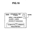
- FIG. 16 is a diagram showing an example of the contents of received schedule data which is displayed on the display portion 12. Time “January 21, 1996 12:58 AM” and an icon indicating that received data is schedule data are displayed on the uppermost line of the display portion. Moreover, received schedule data is displayed on the second to fourth lines while being line-fed at the insertion position of the item switching code "[]".
- a guide message indicating that received data is transferred to and stored in the schedule data memory SD of the RAM 30 if the execute key 13k is operated is displayed on the lowermost line of the display portion 12.
- step A4 If it is determined in step A4 that the mode code at the leading end of received message data is not the code indicating the schedule mode, the control unit 25 causes the driver 31 to selectively operate any one of the loudspeaker unit 34, the vibrator 35 or the LED 36, which has been set, to notify receipt of the message by buzzer sound, vibrations or light flickering. Moreover, received data stored in the received message data memory RD, that is, data in a mode except the schedule mode, is displayed on the display portion 12 at a line-feeding position in accordance with the included item switching code "[]" (step A6). Thus, the foregoing process is temporarily completed.
- the message data is not related to the mode but it is the message data for only a the message.
- the control unit 25 causes the driver 31 to selectively operate any one of the loudspeaker unit 34, the vibrator 35 or the LED 36, which has been set, to notify receipt of the message by buzzer sound, vibrations or light flickering.
- received data stored in the received message data memory RD is allowed to remain when displayed on the display portion 12 (step A7). Thus, the foregoing process is temporarily completed.
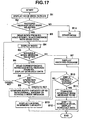
- FIG. 17 is a diagram mainly showing the operation which is performed by the control unit 25 in the received message display mode.
- the mode menu screen shown in FIG. 11 is displayed on the display portion 12 (step B1).
- step B3 When the cursor key 131 has been operated on the mode menu screen to move the menu cursor MC and the execute key 13k has been operated in a state where the icon of the received message display mode with the numeral "1" is in an inverted screen, it is determined that a mode for displaying the message data stored in the received message data memory RD of the RAM 30 has been selected in step B2 following step B1.
- each index portion of the plurality of stored the message data items for example, seven digits are read from the received message data memory RD. If the leading end has a mode code, a corresponding display symbol is read from the mode code table MT of the ROM 29 in accordance with the mode code (step B3).
- FIG. 18 is a diagram showing an example of the contents stored in the received message data memory RD of the RAM 30 of the electronic notebook 1B. Each stored the message data is provided with a confirmation flag indicating whether or not a user has confirmed when the message data has been received and storage address.
- the message data having storage address "05" is formed of the mode code surrounded by a dashed line and the schedule data transmitted from the electronic notebook 1A with the item switching code "[]".
- Mode codes "][2" indicating data in the schedule mode is provided to the leading end of the schedule data.
- the item switching code "[]” is provided between items of data.
- control unit 25 reads the index portion of each the message data, that is, a portion for seven digits, from the received message data memory RD of the RAM 30. Moreover, in accordance with the mode code "][2" of schedule data having the storage address "05", the control unit 25 reads a display symbol of the schedule mode from the mode code table MT of the ROM 29.
- the control unit 25 uses the read index portion of the message data and the mode display symbol to display the index on the display portion 12 (step B4).
- FIG. 19 is a diagram showing an example of a state where the index portions of the message data are read from the received message data memory RD shown in FIG. 18 and the same are displayed on the display portion 12.
- the message data having no mode code is, by 7 digits or smaller, read from the received message data memory RD such that two characters of "kana” except “kanji”, numerals and alphabets are counted as one digit, and then displayed on the display portion 12.
- Schedule data is provided with the display symbol for the schedule mode read from the mode code table MT of the ROM 29 at the leading end when displayed. Moreover, only date data "19960401" is read from the received message data memory RD in accordance with a predetermined format so that display is performed such that "April 1, 1996".
- step B5 In a state where the indexes of received message data are being displayed, whether or not the message data of the schedule mode has been selected is determined (step B5).
- the message data of the schedule data is read from the received message data memory RD so as to be displayed on the display portion 12 (step B6).
- receipt time "January 21, 1996 12:58 AM” and an icon indicating a fact that received data is schedule data are displayed at the uppermost position, as shown in FIG. 16. Moreover, schedule data supplied from the electronic notebook 1A are displayed on the second to the fourth lines with line-fed on the basis of the item switching code "[]".
- a guide message is displayed on the lowermost line in the display portion 12 such that operation of the execute key 13k enables the received data to be, as it is, transferred and stored in the schedule data memory SD of the ROM 29.
- step B7 In a state where received message data of the schedule mode is being displayed, whether or not the execute key 13k or the cancel key 13j has been operated is detected (step B7).
- step B9 an empty capacity of the schedule data memory SD and the overall quantity of the message data which must be stored are compared with each other (step B9) to determine whether or not the empty capacity of the schedule data memory SD is larger than the overall quantity of the message data, that is, whether or not the message data can be stored in the schedule data memory SD as it is (step B10)
- the message data is transferred to the schedule data memory SD so as to be stored.
- the message data of the schedule mode is deleted from the received message data memory RD (step B11). Then, the mode is automatically shifted from the received message display mode to the schedule mode.
- Schedule data which has been newly stored in the schedule data memory SD is displayed on the display portion 12 to confirm that the message data has been registered as schedule data (step B12). Thus, the process shown in FIG. 17 is completed.
- FIG. 20 is a diagram showing an example of a state of display on the display portion 12 of the electronic notebook 1B in the above-mentioned state.
- facts that "Movies at Yurakucho” has been received as schedule data at "12:00 PM to 14:00 PM” on “April 1, 1996 (Monday)” and an alarm has been set at "11:00 AM” are displayed with two bell icons AC.
- step B10 If it is determined in step B10 that the empty capacity of the schedule data memory SD is not more than the overall quantity of the message data and that the message data cannot be stored in the schedule data memory SD as it is, the empty capacity of the schedule data memory SD is too small. Therefore, a fact that transfer of the message data cannot be performed is displayed on the display portion 12 with a predetermined guide message (step B13). Thus, the process shown in FIG. 17 is completed.
- FIG. 21 is a diagram showing an example of a state of display on the display portion 12 in the foregoing state.
- a display symbol in the form of a hand having a plate in which mark " ⁇ " is written and a guide message "Move is inhibited because memory is full” is displayed to urge the user of the electronic notebook 1B to recognize a necessity of arranging the schedule data memory SD if the received message data is important to be stored in the schedule data memory SD as the user's schedule data.
- step B8 If it is determined in step B8 that the execute key 13k is not operated but the cancel key 13j has been operated, it means a confirmation that the received message data of the schedule mode is not required to be stored in the schedule data memory SD of the own electronic notebook as schedule data. Therefore, the operation is returned from the state where the message data is being displayed to a state where the indexes are displayed in step B4.
- step B5 If it is determined in step B5 that the message data except the schedule mode has been selected in a state where the indexes of the received message data are being displayed, the selected the message data is, as it is, read from the received message data memory RD and displayed on the display portion 12 (step B7). Thus, the process shown in FIG. 17 is completed.
- step B2 If it is determined in step B2 that a mode except the received message display mode has been selected from the mode menu screen, a process corresponding to the selected mode is performed as described later (step B14).
- the transmission-side electronic notebook 1A selects schedule data stored in the schedule data memory SD of the RAM 30 to transmit the same as the message data.
- the receiving-side electronic notebook 1B is operated such that the execute key 13k is operated when receipt of the message data has been notified or the received message display mode has been set.
- the message data is transferred to the schedule data memory SD of the RAM 30 as the own schedule data.
- data in other modes can be transmitted as the message data and the receiving side is able to store it in a memory region in the corresponding mode by a simple key operation, as well as schedule data in the schedule data memory SD corresponding to the schedule mode.
- FIG. 22 is a diagram following FIG. 18 and showing contents stored in the received message data memory RD of the RAM 30 of the receiving-side electronic notebook 1B.
- the message data at the storage address "06" is formed of a mode code surrounded by a dashed line and address-book data supplied from the electronic notebook 1A in accordance with the item switching code.
- Mode code "][3" indicating that data is address mode data is provided for the leading end of the message data.
- twelve item switching codes "[]" respectively are provided between items in data.
- the message data at the storage address "07” is memorandum data supplied from the electronic notebook 1A.
- Mode code "][4" indicating that data is memorandum mode data is provided for the leading end of the message data. Only one item switching code "[ ]" is provided between items of data.
- the message data at the storage address "08" is group talk data supplied from the electronic notebook 1A.
- Mode code "][1" indicating group talk data is provided for the leading end of the message data.
- Two item switching codes "[]" are provided between items of data.
- the message data at the storage address "09" is "To Do” data supplied from the electronic notebook 1A.
- Mode code "][5" indicating "To Do” data is provided for the leading end of the message data.
- Three item switching codes "[ ]” are provided between items of data.
- the index portions of respective message data in the received message data memory RD are read as shown in FIG. 17. Moreover, corresponding display symbols are read from the mode code table MT of the ROM 29 in accordance with the mode codes added to the leading ends (step B3). The read index portion of the message data and the display symbols of the mode codes are used so that indexes are displayed as shown in FIG. 23 (step B4).
- FIG. 24 is a diagram showing an example of the contents stored in the address-book data memory DB of the RAM 30 of the electronic notebook 1A.
- a plurality of sets of address-book data items are stored each consisting of name which is the first item, reading which is the second item, telephone number which is the third item, the type of the pager receiver which is the fourth item, the call number of the pager which is the fifth item, address which is the sixth item, an icon which is the seventh item and another information item which is the eighth item.
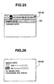
- FIG. 25 is a diagram showing an example of indexes in the address book displayed on the display portion 12. A fact that the first letter of address-book data which is being displayed on the first line belongs to "k" letter group is displayed. Moreover, the index portions of the address book mode read from the address-book data memory DB, which are names in this case, are displayed on the second and following lines.
- name "Kazuo Kato" has been brought to an inverted screen state by the data cursor DC by operating the cursor key 13l.
- the execute key 13k is operated in the foregoing state, the operation is detected so that address-book data is read from the address-book data memory DB so as to be displayed on the display portion 12.
- FIG. 26 is a diagram showing an example of a state of display on the display portion 12. Name is displayed on the first line, the icon of a telephone set and telephone number are displayed on the second line, an inverted letter of "Kan" corresponding to the type of the pager receiver and call number of the pager are displayed on the third line and address and so forth are displayed on the fourth and fifth lines.
- names are read from the contents stored in the address-book data memory DB of the RAM 30 in order to select the receiving-side apparatus so as to be displayed on the display portion 12. Since the process from the selection of the receiving-side apparatus to the transmission operation is similar to the operation which is performed when schedule data is transmitted, the similar process is omitted from description.
- contents as shown in FIG. 27 are displayed when data has been supplied or when address-book data has been selected in a state of display of the indexes in the received message display mode shown in FIG. 23.
- time of receipt "January 21, 1996 01:59 PM" and the icon indicating that received data is address-book data are displayed on the uppermost line. Moreover, a portion of address-book data supplied from the electronic notebook 1A is displayed on the second to fourth lines while being line-fed to correspond the item switching code "[]".
- a guide message is displayed on the lowermost line of the display portion 12, the guide message indicating that operation of the execute key 13k enables the received message to be, as it is, transferred and stored in the address-book data memory DB of the ROM 29.
- the execute key 13k has been operated in accordance with the guide message in the foregoing state where the received message data in the address book mode is displayed, it means a fact that the received message data in the address book mode is stored by the user of the electronic notebook 1B in the address-book data memory DB of the own RAM 30 as address-book data.
- the message data can be stored as a result of the comparison between the empty capacity of the address-book data memory DB and the overall quantity of the message data. Then, the message data is transferred and stored in the address-book data memory DB. On the other hand, the message data in the corresponding address book mode is deleted from the received message data memory RD. Then, the mode is, as it is, shifted from the received message display mode to the address book mode. Then, address-book data, which has been newly stored in the address-book data memory DB, is displayed on the display portion 12 similarly to the case shown in FIG. 26 to confirm that the message data has been registered as address-book data.
- FIG. 28 is a diagram showing an example of the contents stored in the memorandum data memory MD of the RAM 30 of the electronic notebook 1A.
- a plurality of sets of memorandum data items are stored while being provided with storage addresses, each set being composed of the contents of the memorandum which are the first item and an icon which is the second item.
- memorandum data is read from the memorandum data memory MD so as to be displayed on the display portion 12.
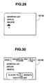
- FIG. 29 is a diagram showing an example of display on the display portion 12. The contents of the memorandum are displayed on the first to third lines and an icon is displayed on the fourth line.
- names are read from the contents stored in the address-book data memory DB of the RAM 30 in order to select the receiving-side apparatus so as to be displayed on the display portion 12 in the form of a list. Since the process to be performed from the selection of the receiving-side apparatus to the transmission is similar to the process which is performed when schedule data or address-book data is transmitted, the similar process is omitted from description.
- display as shown in FIG. 30 is performed when memorandum data has been supplied or when memorandum data has been selected in the display state of the indexes in the received message display mode shown in FIG. 23.
- time of receipt "January 22, 1996 07:56 AM” and an icon indicating received data is memorandum data are displayed on the uppermost line.
- a portion of memorandum data supplied from the pager receiver 1A is line-fed corresponding to the line feeding code in the contents of the memorandum so as to be displayed on the second to fourth lines.
- a guide message indicating that operation of the execute key 13k enables the received message to be, as it is, transferred and stored in the memorandum data memory MD of the ROM 29 is displayed on the lowermost line in the display portion 12.
- the message data can be stored as a result of the comparison performed between the empty capacity of the memorandum data memory MD and the overall quantity of the message data. Then, the message data is transferred and stored in the memorandum data memory MD. On the other hand, the message data in the memorandum mode is deleted from the received message data memory RD. Then, the mode is, as it is, automatically shifted from the received message display mode to the memorandum mode. Memorandum data, which has been newly stored in the memorandum data memory MD, is displayed on the display portion 12 similarly to the case shown in FIG. 29. Thus, a fact that the message data has been registered as memorandum data is confirmed.
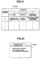
- FIG. 31 is a diagram showing an example of the contents stored in the group talk memory GT of the RAM 30 of the electronic notebook 1A.
- a plurality of sets of group talk data are stored while being provided with storage addresses, each set consisting of file name, which is the first item, a sender name, which is the second item and the contents of the message, which are the third item.
- group talk data is read from the group talk memory GT so as to be displayed on the display portion 12.
- FIG. 32 is a diagram showing a state of display on the display portion 12.
- File name which is the first item is displayed on the first line
- name of the sender which is the second item is displayed on the second line
- contents of the message, which are the third item are displayed on the third to fourth lines.
- names are read from the contents stored in the address-book data memory DB of the RAM 30 in order to select the receiving-side apparatus so as to be displayed on the display portion 12 as a list. Since the process which is performed from the selection of the receiving-side apparatus to the transmission of data is similar to the process which is performed when the schedule data or the address-book data is transmitted, the similar process is omitted from description.
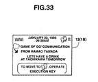
- display as shown in FIG. 33 is performed when group talk data has been supplied or when group talk data has been selected in the display state of the indexes in the received message display mode shown in FIG. 23.
- time of receipt "January 22, 1996 09:58 AM” and an icon indicating that received data is group talk data are displayed on the uppermost line.
- a portion of group talk data supplied from the electronic notebook 1A is line-fed in accordance with the item switching code when group talk data is displayed on the second to fourth lines.
- a guide message is displayed on the lowermost line in the display portion 12, the guide message indicating a fact that the operation of the execute key 13k enables the foregoing received message to be transferred and stored in the group talk memory GT of the ROM 29 as it is.
- execute key 13k If the execute key 13k is operated in accordance with the guide message in the state where received message data in the group talk mode is being displayed, it means that the user of the electronic notebook 1B confirms that the received message data in the group talk mode is stored in the group talk memory GT of the RAM 30 as group talk data.
- the message data can be stored as a result of a comparison performed between the empty capacity of the group talk memory GT and the overall quantity of the message data. Then, the message data is transferred and stored in the group talk memory GT. On the other hand, the message data of the group talk mode is deleted from the received message data memory RD. Then, the mode is, as it is, automatically shifted from the received message display mode to the group talk mode. Group talk data, which has been newly stored in the group talk memory GT, is displayed on the display portion 12 similarly to the case shown in FIG. 32. Thus, a fact that the message data has been registered as group talk data is confirmed.
- FIG. 34 is a diagram showing an example of the contents stored in the "To Do" data memory TD of the RAM 30 of the pager receiver 1A.
- a plurality of sets of "To Do" data are stored while being provide with storage addresses, each set consisting of a check state flag which is the first item, the contents of "To Do" which is the second item, an icon which is the third item and check time which is the fourth item.
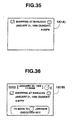
- FIG. 35 is a diagram showing an example of a state of display on the display portion 12.
- a check symbol corresponding to the check state flag which is the first item and the contents of "To Do" which is the second item are displayed on the first line and check time which is the fourth item is displayed on the second line.
- names are read from the contents stored in the address-book data memory DB of the RAM 30 in order to select the receiving-side apparatus so as to be displayed on the display portion 12 as a list.
- the process which is performed form the selection of the receiving-side apparatus to the transmission of the data is similar to the operation which is performed when schedule data, address-book data or group talk data is transmitted. Therefore, the similar process is omitted from description.
- display as shown in FIG. 33 is performed when “To Do” data has been supplied or when "To Do” data has been selected in the state of display of the indexes in the received message display mode shown in FIG. 23.
- receipt time "January 22, 1996 11:58 AM” and an icon indicating a fact that received data is "To Do” data are displayed on the uppermost position.
- "To Do" data supplied from the electronic notebook 1A is displayed on the second to fourth lines while being line-fed in accordance with the item switching code.
- a guide message is displayed on the lowermost line in the display portion 12, the guide message indicating a fact that operation of the execute key 13k enables the received message to be, as it is, transferred and stored in the "To Do" data memory TD.
- the transmission data is converted into DTMF signal so as to be emitted from the loudspeaker unit 18 as sound
- the transmission data may be converted into infrared ray signal so as to be output and transmitted from the IR transmitting/receiver 14. Further, the transmission data may be output and transmitted from the connector 38.
- the foregoing embodiment is applied to the electronic notebook having the paging signal receiving function and the dial tone output function
- the present invention is not limited to this.
- the present invention may, of course, be applied to a variety of electronic apparatuses, for example, digital portable telephones, transceivers, data communication terminals and the like, which perform wireless transmission.
- the data transmitted from the transmission apparatus can be stored in a classified region on the storage means of the receiving-side apparatus to correspond to the attribute of data with a simple instruction operation for confirming received data so that data is shared.
- user of this information management apparatus is able to transmit data of a type having an attribute regardless of the attribute.
- received data can be stored in a classified region on the storage means corresponding to the attribute of received data with a simple instruction operation for confirming the attribute of data.
Landscapes
- Physics & Mathematics (AREA)
- Engineering & Computer Science (AREA)
- Computer Networks & Wireless Communication (AREA)
- Electromagnetism (AREA)
- General Physics & Mathematics (AREA)
- Signal Processing (AREA)
- Mobile Radio Communication Systems (AREA)
- Calculators And Similar Devices (AREA)
- Communication Control (AREA)
Claims (21)
- Un appareil de réception d'information comprenant :caractérisé parun moyen de réception (22) pour recevoir des éléments de données et des attributs des éléments de données;un premier moyen de mémoire (30) incluant des zones de stockage (GT, SD, DB, MD, TD);
un moyen de visualisation (12) pour visualiser l'un des éléments de données reçus et un message de guidage, conformément à l'attribut de l'élément de données reçu, le message de guidage indiquant une zone de stockage correspondant à l'élément de données visualisé;
un moyen (26, 13k, 13j) pour émettre une instruction de stockage en réponse à une première opération manuelle effectuée par un utilisateur, et une instruction d'annulation en réponse à une seconde opération manuelle effectuée par l'utilisateur;
un moyen pour stocker l'élément de données visualisé dans la zone de stockage indiquée du premier moyen de mémoire, en réponse à l'instruction de stockage; et
un moyen de commande de visualisation (25) pour faire en sorte que le moyen de visualisation visualise un autre des éléments de données reçus et un message de guidage correspondant, en réponse à l'instruction d'annulation. - L'appareil selon la revendication 1, caractérisé en ce que le moyen de réception reçoit un signal incluant l'élément de données et un code d'instruction représentant l'attribut de l'élément de données.
- L'appareil selon la revendication 2, caractérisé en ce que le moyen de réception reçoit un signal de tonalités de numérotation incluant l'élément de données et le code d'instruction.
- L'appareil selon la revendication 2 ou 3, caractérisé en ce que le premier moyen de mémoire comprend une zone de stockage sans classification (RD) pour stocker l'élément de données reçu et le code d'instruction reçu; et
le moyen de visualisation visualise sélectivement l'un des éléments de données stockés dans la zone de stockage sans classification. - L'appareil selon l'une des revendications 1 à 4, caractérisé en ce qu'il comprend en outre :une mémoire tampon (28) pour stocker les éléments de données reçus; etun moyen pour déplacer vers le premier moyen de mémoire l'élément de données stocké dans la mémoire tampon, et effacer l'élément de données de la mémoire tampon en réponse à l'instruction de stockage.
- L'appareil selon l'une des revendications 1 à 5, caractérisé en ce que :le moyen de commande comprend un moyen (25) pour détecter si une zone restante du premier moyen de mémoire est insuffisante ou non pour stocker l'élément de données visualisé, etle moyen de visualisation visualise un message d'avertissement lorsque la zone restante du premier moyen de mémoire est insuffisante pour stocker l'élément de données visualisé.
- L'appareil selon l'une des revendications 1 à 6, caractérisé en ce qu'il comprend en outre :un moyen (25) pour comparer une quantité de données de l'élément de données visualisé avec une quantité de données de zone vide de la zone de stockage correspondant à l'attribut de l'élément de données visualisé;un moyen pour autoriser le moyen de stockage à stocker l'élément de données visualisé dans la zone de stockage indiquée, si la quantité de données de la zone vide est plus grande que la quantité de données de l'élément de données visualisé; etun moyen pour interdire au moyen de stockage de stocker l'élément de données visualisé dans la zone de stockage indiquée, et pour signaler cette interdiction à un utilisateur si la quantité de données de la zone vide n'est pas plus grande que la quantité de données de l'élément de données visualisé.
- L'appareil selon l'une des revendications 1 à 7, caractérisé en ce que l'élément de données comprend au moins un d'un élément de données d'emploi du temps informant un utilisateur au sujet d'un emploi du temps d'une personne émettrice, d'un élément de données de carnet d'adresses, d'un élément de données "à faire", et d'un élément de données de notes.
- L'appareil selon la revendication 4, caractérisé en ce que le moyen de commande de visualisation comprend :un moyen (12) pour commander au moyen de visualisation de visualiser des index des éléments de données reçus stockés dans la zone de stockage sans classification (RD) du premier moyen de mémoire;un moyen (26; 13l) pour sélectionner l'un des index visualisés sur le moyen de visualisation;un moyen (12) pour visualiser un élément de données qui correspond à l'index sélectionné et le message de guidage, lorsque le sélecteur sélectionne l'un des index; etun moyen (12) pour visualiser une confirmation du fait que l'élément de données est stocké dans le premier moyen de mémoire, après que l'élément de données sélectionné a été stocké dans le premier moyen de mémoire.
- Un système de communication incluant un appareil de réception d'information selon l'une des revendications 1 à 9, et un appareil d'émission d'information (1A) comprenant :un second moyen de mémoire (30) ayant des zones de stockage, pour stocker des éléments de données, etun moyen (14, 33, 37) pour émettre des éléments de données lus dans le second moyen de mémoire et des attributs des éléments de données lus.
- Le système de communication selon la revendication 10, caractérisé en ce que le moyen d'émission comprend :un moyen (26, 13l) pour sélectionner un élément de données à émettre, parmi les éléments de données stockés dans le second moyen de mémoire; etun moyen pour émettre un signal incluant un élément de données sélectionné et un code d'instruction pour spécifier l'attribut de l'élément de données sélectionné.
- Le système de communication selon la revendication 10 ou 11, dans lequel le moyen d'émission comprend un moyen pour convertir, en un signal de tonalités de numérotation, le signal incluant l'élément de données sélectionné et le code d'instruction, de façon à émettre séquentiellement le signal.
- Un procédé pour commander un appareil de réception d'information, le procédé comprenant :caractérisé parla réception (A1, B2) d'éléments de données et d'attributs des éléments de données;le stockage des éléments de données reçus dans un premier moyen de mémoire incluant des zones de stockage (GT, SD, DB, MD, TD);
la visualisation (A5) de l'un des éléments de données reçus et d'un message de guidage, conformément à l'attribut de l'élément de données reçu, le message de guidage indiquant une zone de stockage du premier moyen de stockage correspondant à l'élément de données visualisé;
l'émission (B8) d'une instruction de stockage en réponse à une première opération manuelle effectuée par un utilisateur, et d'une instruction d'annulation en réponse à une seconde opération manuelle effectuée par l'utilisateur;
le stockage (B11) de l'élément de données visualisé dans la zone de stockage indiquée du premier moyen de mémoire, en réponse à l'instruction de stockage; et
la visualisation (B8, B4) d'un autre des éléments de données reçus et d'un message de guidage correspondant, en réponse à l'instruction d'annulation. - Le procédé selon la revendication 13, caractérisé en ce qu'un signal incluant l'élément de données et un code d'instruction représentant l'attribut de l'élément de données est reçu.
- Le procédé selon la revendication 14, caractérisé en ce qu'un signal de tonalités de numérotation incluant l'élément de données et le code d'instruction est reçu.
- Le procédé selon la revendication 14 ou 15, caractérisé en ce que le premier moyen de mémoire comprend une zone de stockage sans classification (RD) pour stocker l'élément de données reçu et le code d'instruction reçu; et
l'un des éléments de données stockés dans le moyen de stockage sans classification est visualisé sélectivement. - Le procédé selon l'une des revendications 13 à 17, caractérisé par
le stockage (A1) des éléments de données reçus dans une mémoire tampon; et
le transfert (B11) vers le premier moyen de mémoire de l'élément de données stocké dans la mémoire tampon, et l'effacement de l'élément de données de la mémoire tampon en réponse à l'instruction de stockage. - Le procédé selon l'une des revendications 13 à 17, caractérisé par :la détection (B9, B10) du fait qu'une zone restante du premier moyen de mémoire est suffisante ou non pour stocker l'élément de données visualisé, etla visualisation (B13) d'un message d'avertissement lorsque la zone restante du premier moyen de mémoire est insuffisante pour stocker l'élément de données visualisé.
- Le procédé selon l'une des revendications 13 à 18, caractérisé en ce qu'il comprend en outre :la comparaison (B9) d'une quantité de données de l'élément de données visualisé avec une quantité de données de zone vide de la zone de stockage correspondant à l'attribut de l'élément de données visualisé;l'opération consistant à autoriser (B11) le moyen de stockage à stocker l'élément de données visualisé dans la zone de stockage indiquée, si la quantité de données de la zone vide est plus grande que la quantité de données de l'élément de données visualisé; etl'opération consistant à interdire (B13) au moyen de stockage de stocker l'élément de données visualisé dans la zone de stockage indiquée, et à signaler cette interdiction à l'utilisateur si la quantité de données de la zone vide n'est pas plus grande que la quantité de données de l'élément de données visualisé.
- Le procédé selon l'une des revendications 13 à 19, caractérisé en ce que l'élément de données comprend au moins un d'un élément de données d'emploi du temps informant un utilisateur au sujet d'un emploi du temps d'une personne émettrice, d'un élément de données de carnet d'adresses, d'un élément de données "à faire", et d'un élément de données de notes.
- Le procédé selon la revendication 16, caractérisé par
la visualisation (B4) d'index des éléments de données reçus stockés dans la zone de stockage sans classification (RD) du premier moyen de mémoire;
la réception d'une sélection de l'un des index visualisés sur le moyen de visualisation;
la visualisation (B6) d'un élément de données qui correspond à l'index sélectionné et du message de guidage; et
la visualisation (B12) d'une confirmation du fait que l'élément de données est stocké dans le premier moyen de mémoire, après que l'élément de données sélectionné a été stocké dans le premier moyen de mémoire.
Applications Claiming Priority (3)
| Application Number | Priority Date | Filing Date | Title |
|---|---|---|---|
| JP4454896 | 1996-03-01 | ||
| JP44548/96 | 1996-03-01 | ||
| JP4454896 | 1996-03-01 |
Publications (3)
| Publication Number | Publication Date |
|---|---|
| EP0798621A2 EP0798621A2 (fr) | 1997-10-01 |
| EP0798621A3 EP0798621A3 (fr) | 1999-10-27 |
| EP0798621B1 true EP0798621B1 (fr) | 2005-05-04 |
Family
ID=12694562
Family Applications (1)
| Application Number | Title | Priority Date | Filing Date |
|---|---|---|---|
| EP97103143A Expired - Lifetime EP0798621B1 (fr) | 1996-03-01 | 1997-02-26 | Système de communication de données et dispositif de gestion d'informations |
Country Status (7)
| Country | Link |
|---|---|
| US (1) | US6374304B1 (fr) |
| EP (1) | EP0798621B1 (fr) |
| KR (1) | KR100244015B1 (fr) |
| CN (1) | CN1140093C (fr) |
| DE (1) | DE69733167T2 (fr) |
| HK (1) | HK1005676A1 (fr) |
| ID (1) | ID16100A (fr) |
Families Citing this family (26)
| Publication number | Priority date | Publication date | Assignee | Title |
|---|---|---|---|---|
| JP4126473B2 (ja) * | 1998-01-23 | 2008-07-30 | カシオ計算機株式会社 | 電子機器、記憶媒体、及びデータ表示方法 |
| JP4098435B2 (ja) * | 1999-03-12 | 2008-06-11 | 富士通株式会社 | 情報管理装置及びデータ生成方法並びに情報管理プログラムを格納したコンピュータ読取り可能な記録媒体 |
| KR100364477B1 (ko) * | 1999-06-29 | 2002-12-16 | 에스케이 텔레콤주식회사 | 이동통신 시스템에서 단말기의 메모 메시지 수신 및 전송방법 |
| US20020165916A1 (en) * | 2001-05-07 | 2002-11-07 | Katsutoshi Kitamura | Method of providing information |
| GB2377149A (en) * | 2001-06-30 | 2002-12-31 | Hewlett Packard Co | Electronic reminders |
| US7881743B2 (en) * | 2001-10-16 | 2011-02-01 | Research In Motion Limited | Handheld mobile communication device |
| US9715678B2 (en) | 2003-06-26 | 2017-07-25 | Microsoft Technology Licensing, Llc | Side-by-side shared calendars |
| US7707255B2 (en) | 2003-07-01 | 2010-04-27 | Microsoft Corporation | Automatic grouping of electronic mail |
| US8799808B2 (en) * | 2003-07-01 | 2014-08-05 | Microsoft Corporation | Adaptive multi-line view user interface |
| US8255828B2 (en) | 2004-08-16 | 2012-08-28 | Microsoft Corporation | Command user interface for displaying selectable software functionality controls |
| US7895531B2 (en) | 2004-08-16 | 2011-02-22 | Microsoft Corporation | Floating command object |
| US9015621B2 (en) | 2004-08-16 | 2015-04-21 | Microsoft Technology Licensing, Llc | Command user interface for displaying multiple sections of software functionality controls |
| US8146016B2 (en) | 2004-08-16 | 2012-03-27 | Microsoft Corporation | User interface for displaying a gallery of formatting options applicable to a selected object |
| US7703036B2 (en) | 2004-08-16 | 2010-04-20 | Microsoft Corporation | User interface for displaying selectable software functionality controls that are relevant to a selected object |
| US7747966B2 (en) | 2004-09-30 | 2010-06-29 | Microsoft Corporation | User interface for providing task management and calendar information |
| US9542667B2 (en) | 2005-09-09 | 2017-01-10 | Microsoft Technology Licensing, Llc | Navigating messages within a thread |
| US8627222B2 (en) | 2005-09-12 | 2014-01-07 | Microsoft Corporation | Expanded search and find user interface |
| US9727989B2 (en) | 2006-06-01 | 2017-08-08 | Microsoft Technology Licensing, Llc | Modifying and formatting a chart using pictorially provided chart elements |
| KR100822295B1 (ko) * | 2006-12-07 | 2008-04-16 | 삼성전자주식회사 | 메시지 정보 표시 방법 및 시스템 |
| US8484578B2 (en) | 2007-06-29 | 2013-07-09 | Microsoft Corporation | Communication between a document editor in-space user interface and a document editor out-space user interface |
| US8201103B2 (en) | 2007-06-29 | 2012-06-12 | Microsoft Corporation | Accessing an out-space user interface for a document editor program |
| US8762880B2 (en) | 2007-06-29 | 2014-06-24 | Microsoft Corporation | Exposing non-authoring features through document status information in an out-space user interface |
| US9588781B2 (en) | 2008-03-31 | 2017-03-07 | Microsoft Technology Licensing, Llc | Associating command surfaces with multiple active components |
| US9665850B2 (en) | 2008-06-20 | 2017-05-30 | Microsoft Technology Licensing, Llc | Synchronized conversation-centric message list and message reading pane |
| US8402096B2 (en) | 2008-06-24 | 2013-03-19 | Microsoft Corporation | Automatic conversation techniques |
| US9046983B2 (en) | 2009-05-12 | 2015-06-02 | Microsoft Technology Licensing, Llc | Hierarchically-organized control galleries |
Family Cites Families (8)
| Publication number | Priority date | Publication date | Assignee | Title |
|---|---|---|---|---|
| US4486853A (en) | 1981-04-01 | 1984-12-04 | Telemet American, Inc. | Apparatus for receiving and displaying continuously updated data |
| US4473824A (en) | 1981-06-29 | 1984-09-25 | Nelson B. Hunter | Price quotation system |
| US5038284A (en) | 1988-02-17 | 1991-08-06 | Kramer Robert M | Method and apparatus relating to conducting trading transactions with portable trading stations |
| JP3376604B2 (ja) | 1992-07-20 | 2003-02-10 | カシオ計算機株式会社 | 情報管理装置 |
| JP3168756B2 (ja) * | 1993-02-24 | 2001-05-21 | ミノルタ株式会社 | 電子メールシステムのメール管理方法 |
| US5493692A (en) * | 1993-12-03 | 1996-02-20 | Xerox Corporation | Selective delivery of electronic messages in a multiple computer system based on context and environment of a user |
| JP2591462B2 (ja) * | 1993-12-28 | 1997-03-19 | 日本電気株式会社 | 無線選択呼出受信機 |
| US5740369A (en) * | 1994-06-17 | 1998-04-14 | Hitachi, Ltd. | Information delivery system and portable information terminal |
-
1997
- 1997-02-24 US US08/804,820 patent/US6374304B1/en not_active Expired - Lifetime
- 1997-02-26 EP EP97103143A patent/EP0798621B1/fr not_active Expired - Lifetime
- 1997-02-26 DE DE69733167T patent/DE69733167T2/de not_active Expired - Lifetime
- 1997-02-28 KR KR1019970006512A patent/KR100244015B1/ko not_active IP Right Cessation
- 1997-02-28 ID IDP970614A patent/ID16100A/id unknown
- 1997-03-03 CN CNB971008086A patent/CN1140093C/zh not_active Expired - Lifetime
-
1998
- 1998-06-04 HK HK98104898A patent/HK1005676A1/xx not_active IP Right Cessation
Also Published As
| Publication number | Publication date |
|---|---|
| DE69733167D1 (de) | 2005-06-09 |
| KR970068196A (ko) | 1997-10-13 |
| CN1140093C (zh) | 2004-02-25 |
| EP0798621A3 (fr) | 1999-10-27 |
| KR100244015B1 (ko) | 2000-02-01 |
| ID16100A (id) | 1997-09-04 |
| HK1005676A1 (en) | 1999-01-22 |
| EP0798621A2 (fr) | 1997-10-01 |
| DE69733167T2 (de) | 2005-10-06 |
| CN1169075A (zh) | 1997-12-31 |
| US6374304B1 (en) | 2002-04-16 |
Similar Documents
| Publication | Publication Date | Title |
|---|---|---|
| EP0798621B1 (fr) | Système de communication de données et dispositif de gestion d'informations | |
| US5903632A (en) | Automated telephone directory | |
| EP1387241B1 (fr) | Terminal de traitment d'informations | |
| US5797089A (en) | Personal communications terminal having switches which independently energize a mobile telephone and a personal digital assistant | |
| EP0529798B1 (fr) | Dispositif sans fil | |
| EP3754954B1 (fr) | Procédé d'affichage d'un événement dans un terminal mobile et terminal mobile le mettant en oeuvre | |
| CN101945161A (zh) | 移动通信装置 | |
| CN1281601A (zh) | 显示接收消息的方法和装置 | |
| EP0498997B1 (fr) | Téléphone avec identification de l'appeleur | |
| JP3363253B2 (ja) | 電子機器 | |
| US6362814B1 (en) | Electronic apparatus | |
| CN1092573A (zh) | 带显示器的传呼接收机 | |
| JPH1013935A (ja) | 無線データ通信方式 | |
| JP3812040B2 (ja) | 情報管理装置 | |
| CA2195355C (fr) | Repertoire telephonique automatise | |
| KR950012592B1 (ko) | 다기능 스마트카드 전화기 시스템 | |
| RU2099876C1 (ru) | Персональное коммуникационное устройство | |
| JPH0965397A (ja) | メッセージ送信機能付無線選択呼出受信機 | |
| JPH09215029A (ja) | データ送信装置 | |
| JP2770218B2 (ja) | オートダイアル機能付きメッセージ受信機 | |
| JP3208252B2 (ja) | 文字を数字に変換し表示する機能を有する選択呼出受信機 | |
| JPH09238202A (ja) | 通信装置 | |
| JPH07162916A (ja) | ボタン電話装置 | |
| JPH1078909A (ja) | データ受信装置 | |
| KR0181111B1 (ko) | 페이저의 문자편집 방법 |
Legal Events
| Date | Code | Title | Description |
|---|---|---|---|
| PUAI | Public reference made under article 153(3) epc to a published international application that has entered the european phase |
Free format text: ORIGINAL CODE: 0009012 |
|
| 17P | Request for examination filed |
Effective date: 19970226 |
|
| AK | Designated contracting states |
Kind code of ref document: A2 Designated state(s): DE FR GB |
|
| RAP1 | Party data changed (applicant data changed or rights of an application transferred) |
Owner name: CASIO COMPUTER CO., LTD. |
|
| PUAL | Search report despatched |
Free format text: ORIGINAL CODE: 0009013 |
|
| AK | Designated contracting states |
Kind code of ref document: A3 Designated state(s): DE FR GB |
|
| RIC1 | Information provided on ipc code assigned before grant |
Free format text: 6G 06F 1/16 A, 6H 04Q 7/08 B, 6H 04L 29/08 B, 6H 04Q 3/32 B, 6H 04M 1/72 B |
|
| 17Q | First examination report despatched |
Effective date: 20020718 |
|
| GRAP | Despatch of communication of intention to grant a patent |
Free format text: ORIGINAL CODE: EPIDOSNIGR1 |
|
| GRAS | Grant fee paid |
Free format text: ORIGINAL CODE: EPIDOSNIGR3 |
|
| GRAA | (expected) grant |
Free format text: ORIGINAL CODE: 0009210 |
|
| AK | Designated contracting states |
Kind code of ref document: B1 Designated state(s): DE FR GB |
|
| REG | Reference to a national code |
Ref country code: GB Ref legal event code: FG4D |
|
| REF | Corresponds to: |
Ref document number: 69733167 Country of ref document: DE Date of ref document: 20050609 Kind code of ref document: P |
|
| PLBE | No opposition filed within time limit |
Free format text: ORIGINAL CODE: 0009261 |
|
| STAA | Information on the status of an ep patent application or granted ep patent |
Free format text: STATUS: NO OPPOSITION FILED WITHIN TIME LIMIT |
|
| ET | Fr: translation filed | ||
| 26N | No opposition filed |
Effective date: 20060207 |
|
| REG | Reference to a national code |
Ref country code: FR Ref legal event code: PLFP Year of fee payment: 20 |
|
| PGFP | Annual fee paid to national office [announced via postgrant information from national office to epo] |
Ref country code: DE Payment date: 20160223 Year of fee payment: 20 |
|
| PGFP | Annual fee paid to national office [announced via postgrant information from national office to epo] |
Ref country code: FR Payment date: 20160108 Year of fee payment: 20 Ref country code: GB Payment date: 20160224 Year of fee payment: 20 |
|
| REG | Reference to a national code |
Ref country code: DE Ref legal event code: R071 Ref document number: 69733167 Country of ref document: DE |
|
| REG | Reference to a national code |
Ref country code: GB Ref legal event code: PE20 Expiry date: 20170225 |
|
| PG25 | Lapsed in a contracting state [announced via postgrant information from national office to epo] |
Ref country code: GB Free format text: LAPSE BECAUSE OF EXPIRATION OF PROTECTION Effective date: 20170225 |