WO2025142264A1 - 導光体 - Google Patents
導光体 Download PDFInfo
- Publication number
- WO2025142264A1 WO2025142264A1 PCT/JP2024/041779 JP2024041779W WO2025142264A1 WO 2025142264 A1 WO2025142264 A1 WO 2025142264A1 JP 2024041779 W JP2024041779 W JP 2024041779W WO 2025142264 A1 WO2025142264 A1 WO 2025142264A1
- Authority
- WO
- WIPO (PCT)
- Prior art keywords
- light
- section
- light guide
- output
- entrance
- Prior art date
- Legal status (The legal status is an assumption and is not a legal conclusion. Google has not performed a legal analysis and makes no representation as to the accuracy of the status listed.)
- Pending
Links
Images





Classifications
-
- G—PHYSICS
- G02—OPTICS
- G02B—OPTICAL ELEMENTS, SYSTEMS OR APPARATUS
- G02B27/00—Optical systems or apparatus not provided for by any of the groups G02B1/00 - G02B26/00, G02B30/00
- G02B27/01—Head-up displays
-
- G—PHYSICS
- G02—OPTICS
- G02B—OPTICAL ELEMENTS, SYSTEMS OR APPARATUS
- G02B27/00—Optical systems or apparatus not provided for by any of the groups G02B1/00 - G02B26/00, G02B30/00
- G02B27/02—Viewing or reading apparatus
-
- H—ELECTRICITY
- H04—ELECTRIC COMMUNICATION TECHNIQUE
- H04N—PICTORIAL COMMUNICATION, e.g. TELEVISION
- H04N5/00—Details of television systems
- H04N5/64—Constructional details of receivers, e.g. cabinets or dust covers
Definitions
- the light guiding section may have a first light guiding section and a second light guiding section adjacent to each other in a direction intersecting the second direction, and a continuous section at a boundary between the first light guiding section and the second light guiding section, where the first light guiding section and the second light guiding section are continuous, and a discontinuous section at the boundary between the first light guiding section and the second light guiding section, where the first light guiding section and the second light guiding section are spaced apart.
- the light may be light emitted from a light emitting source.
- the light source may include a memory unit for storing the information.
- It may be mounted on a harness worn by a user.
- the light output section may output the light toward a display section that displays information.
- An output direction of the light at the light exit position may be parallel to an input direction of the light at the light entry position.
- An output direction of the light at the light exit position may be anti-parallel to an input direction of the light at the light entrance position.
- a display device may comprise a light guide according to any one of claims 1 to 10.
- the display device may include a light emitting source that emits the light.
- the display device may include a display unit onto which the light output from the light guide is projected.
- 5B shows a side view (cross section taken along reference line BB in FIG. 5A ) of the state inside the die after the die and insert setting step in the first manufacturing method.
- 4 shows the flow of resin in a molding process in the first manufacturing method.
- 11 shows a state in which the insert is being pulled out in a insert pulling step in the first manufacturing method.
- 4 shows a second manufacturing flow of the light guide body.
- 13 shows a front view of the state inside the mold after a first mold setting step in the second manufacturing method.
- 11 shows the configurations of a first light entrance portion, a first light guide portion, and a first light exit portion molded in a light entrance portion molding step using a first mold in a second manufacturing method.
- 1 shows the configuration of the bottom surface and the continuous portion of the first light inlet portion, the first light guide portion, and the first light outlet portion.
- 13 shows a second die in the second manufacturing method and the state inside the die after a nesting setting step, as viewed from the front. 13 is a perspective view showing a second die and the state inside the die after a nesting setting step in the second manufacturing method.
- 4 shows a third manufacturing flow of the light guide body.
- 11 shows configurations of a first light entrance portion, a first light guide portion, and a first light exit portion molded in a light entrance portion molding step in the third manufacturing method.
- 11 shows configurations of a second light inlet section, a second light guiding section, and a second light outlet section molded in a light guiding section molding step in the third manufacturing method.
- 13 shows a state in which the first light inlet portion, the first light guide portion, and the first light outlet portion and the second light inlet portion, the second light guide portion, and the second light outlet portion are welded together by the welding step in the third manufacturing method.
- the light guide 100 has an approximately plate shape that extends in two dimensions with the X-axis direction as the short side and the Y-axis direction as the long side, and has a thickness in the Z-axis direction.
- the steps on the -Y and +Z sides of the light entrance section 110 and the steps on the +Y and +Z sides of the light exit section 130 are not shown.
- the light entrance section 110 has a light entrance position 111a arranged so that light is entered from the Z-axis direction, and is an optical member that collects light entered from the light entrance position 111a in the -Z direction, and has a first light entrance section 111 and a second light entrance section 112 adjacent in the Z-axis direction, as well as a continuous section 141 and a discontinuous section 142 provided at the boundary between the first light entrance section 111 and the second light entrance section 112.
- the first light entrance section 111 and the second light entrance section 112 are integrally stacked in the Z-axis direction.
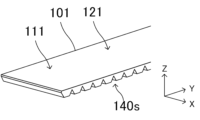
- two adjacent focusing elements 90 form a hollow space (simply referred to as space) 140s between them that has a triangular cross section and extends in the X-axis direction.
- the multiple focusing elements 90 may be arranged in parallel and spaced apart from each other in the Y-axis direction. In such a case, the light entrance position 111a is provided on the +Z surface of one or some of the multiple focusing elements 90.
- the boundary between the light-collecting element 90 and the space 140s, i.e., the ⁇ Y side surfaces of the light-collecting element 90, function as reflective surfaces 92, 93 that reflect, in the ⁇ Y and -Z directions, a portion of the light input into the light-collecting element 90 from the Z-axis direction at the light-entering position 111a.
- the portion of the focusing element 90 between the reflecting surfaces 92, 93 functions as a translucent portion 94 that transmits a portion of the light input from the light entrance position 111a (the remaining portion that does not enter the reflecting surfaces 92, 93 in this embodiment) and the reflected light reflected by the reflecting surfaces 92, 93.
- the second light entrance section 112 is the lower section of the light entrance section 110, and is a section that guides the light reflected by the reflecting surfaces 92, 93 of the first light entrance section 112 to the light guide section 120.
- the second light entrance section 112 is made of the same material as the first light entrance section 111 and is formed into a plate shape that extends in the XY directions and has a thickness in the Z axis direction.
- the continuous portion 141 is provided so that the light-transmitting portion 94 of the first light entrance portion 111 and the second light entrance portion 112 are physically continuous, and guides the light input from the light entrance position 111a, i.e., the reflected light reflected by the reflecting surfaces 92, 93 (and the remaining light that does not enter the reflecting surfaces 92, 93), to the second light entrance portion 112.
- the continuous portion 141 has an opening width A in the Y-axis direction and extends in the X-axis direction.
- the continuous portion 141 can be formed from the same material as the light-collecting element 90.
- the continuous portion 141 may also be formed integrally with the first light entrance portion 111 and/or the second light entrance portion 112 as part of them.
- the discontinuous portion 142 is provided so that the reflecting surfaces 92, 93 of the first light entrance portion 111 and the second light entrance portion 112 are spaced apart, and are disposed adjacent to each of the ⁇ Y sides of the continuous portion 141.
- the discontinuous portion 142 separates the second light entrance portion 112 from the first light entrance portion 111 (the reflecting surfaces 92, 93 formed on the ⁇ Y side surfaces) to form a space 140s (e.g., 140s 7 ) therebetween, so that the interface between the discontinuous portion 142 and the second light entrance portion 112 functions as a reflecting surface that reflects the reflected light input from the light transmitting portion 94 of the first light entrance portion 111 through the continuous portion 141 to the second light entrance portion 112 and guides it to the light guiding portion 120.
- the interface between the discontinuous portion 142 and the second light entrance portion 112, i.e., the +Z end face of the second light entrance portion 112 below the space 140s, may be mirror-finished.
- a reflective film may also be provided using a metal or the like.
- the continuous portion 143 is provided so that the light-transmitting portion 94 of the first light-guiding portion 121 and the second light-guiding portion 122 are physically continuous.
- the discontinuous portion 144 is provided so that the first light guiding portion 121 (reflecting surfaces 92, 93) and the second light guiding portion 122 are spaced apart from each other, similar to the discontinuous portion 142, and is disposed adjacent to each of the ⁇ Y sides of the continuous portion 143.
- the light output section 130 is an optical component having a light output position 131a arranged so that the light guided by the light guide section 120 is output in a direction (in this embodiment, the Z-axis direction) that intersects (or is perpendicular or nearly perpendicular) with the Y-axis direction, and outputs light in the +Z direction from the light output position 131a. It has a first light output section 131 and a second light output section 132 adjacent in the Z-axis direction, as well as a continuous section 145 and a discontinuous section 146 arranged at the boundary between the first light output section 131 and the second light output section 132. In this embodiment, the first light output section 131 and the second light output section 132 are stacked integrally in the Z-axis direction.
- the first light exit section 131 is the upper part of the light exit section 130, and is formed by arranging one or more (one in this embodiment) focusing elements 90 in the Y-axis direction and integrally connecting them, similar to the first light entrance section 111.
- the first light exit section 131 extends in the Y-axis direction, and its +Z surface spreads in the XY direction to form a planar light exit surface, and a light exit position 131a where light is output in the +Z direction is provided on the light exit surface.
- the focusing element 90 has reflecting surfaces 92, 93 and a transparent portion 94 located below (in the -Z direction) the light exit position 131a.
- a space 140s having a triangular cross section and extending in the X-axis direction is formed between two adjacent focusing elements 90.
- the configuration of the focusing element 90 and the reflecting surfaces 92, 93 is the same as that of the light entrance section 110 described above. These reflecting surfaces 92 and 93 reflect the light guided in the Y-axis direction by the light guide section 120 in the Z-axis direction.
- the second light output section 132 is the lower part of the light output section 130, and is a section that sends the light guided through the light guide section 120 (second light guide section 122) to the first light output section 131.
- the second light output section 132 is made of the same material as the first light output section 131 and is formed into a plate shape that extends in the XY directions and has a thickness in the Z-axis direction.
- the light sent by the second light output section 132 to the first light output section 131 is reflected by the reflecting surfaces 92, 93 of the first light output section 131 and is output in the Z-axis direction from the light output position 131a of the light output section 130.
- the continuous portion 145 is provided so that the light-transmitting portion 94 of the first light-emitting portion 131 and the second light-emitting portion 132 are physically continuous.
- the discontinuous portion 146 is provided so that the first light output portion 131 (reflecting surfaces 92, 93) and the second light output portion 132 are spaced apart from each other, similar to the discontinuous portion 142, and is disposed adjacent to each of the ⁇ Y sides of the continuous portion 145.
- the first light entrance section 111, the first light guide section 121, and the first light exit section 131 are arranged in the Y-axis direction and molded as a single unit. These molded parts are also called the upper section 101.
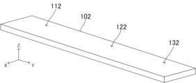
- the second light entrance section 112, the second light guide section 122, and the second light exit section 132 are arranged in the Y-axis direction and molded as a single unit. These molded parts are also called the lower section 102.
- the light entrance section 110, the light guide section 120, and the light exit section 130 are arranged in the Y-axis direction and molded as a single unit.
- the reflective surfaces 92, 93 and translucent portions 94 of the light entrance portion 110, the light guide portion 120, and the light exit portion 130 are arranged in multiple locations along the Y-axis direction within the upper portion 101 of the light guide 100 by arranging the focusing elements 90 in parallel in the Y-axis direction and integrally forming them.
- the discontinuous portions 142, 144, and 146 have a width approximately equal to that of the continuous portions 141, 143, and 145, and are arranged between the continuous portions 141, 143, and 145. This results in an aperture ratio A/P of approximately 1/2. Note that the continuous portions 141, 143, and 145 and the adjacent discontinuous portions 142, 144, and 146 have widths different from each other in the Y-axis direction, and the aperture ratio A/P may be greater than or less than approximately 1/2.
- the reflecting surfaces 92 and 93 of the light entrance portion 110 reflect the light input from the light entrance position 111a toward the second light entrance portion 112.
- the reflecting surfaces 92 and 93 reflect the light input from a direction (in this embodiment, the Z-axis direction) that intersects (or is perpendicular or nearly perpendicular) with the light entrance surface (the +Z surface of the first light entrance portion 111) to which the light entrance position 111a belongs, toward the second light entrance portion 112.
- the light reflected by the reflecting surface 93 forms parallel light and passes through the continuous portion 141; that is, the light reflected at the +Z side of the reflecting surface 93 passes through the +Y side of the continuous portion 141, the light reflected at the center of the reflecting surface 93 passes through the center of the continuous portion 141, and the light reflected at the -Z side of the reflecting surface 93 passes through the -Y side of the continuous portion 141, and then enters the second light entrance portion 112.
- the light reflected by the reflecting surface 92 forms parallel light and enters the second light entrance 112 in the same manner as the light reflected by the reflecting surface 93, except that the light travels in the opposite direction.
- FIG. 2A shows a schematic configuration of the wearing device 200 according to this embodiment and the guidance of light S within the light guide 100.
- the wearing device 200 is, for example, a head-mounted display (HMD) that is worn on the user's head, and includes the light guide 100 and a light emission source 180.
- the light guide 100 is configured as described above.
- the light S is guided from the second light output section 132 to the first light output section 131 via the continuous section 145, is reflected by the reflecting surface 92 toward the light output surface (the +Z surface of the first light output section 131), and is output from the light output position 131a in a direction anti-parallel (opposite) to the input direction of the light S at the light input position 111a, i.e., in the +Z direction.
- the light S output from the light output position 131a enters the eye E of the user. This allows the user to view an image or picture represented by the light.
- the inclination angle of the discontinuous portion 144 and/or the inclination angle of the reflecting surfaces 92, 93 are determined so that the light S that has entered the second light guiding portion 122 does not leak into the first light guiding portion 121 via the continuous portion 143.
- the light S is not limited to being input to the light entrance position 111a in the -Z direction, but may be input at an incline with respect to the Z axis direction, and is not limited to being output from the light exit position 131a in the +Z direction, but may be output at an incline with respect to the Z axis direction.
- the output direction of the light S at the light exit position 131a is opposite to the input direction of the light S at the light entrance position 111a in the Z axis direction.
- the wearing device 200 in this embodiment is a wearing device for one eye, it may also be a wearing device for both eyes that has two wearing devices 200.
- FIG. 3 shows a schematic configuration of the display device 210 and the guidance of light S within the light guide 100.
- the display device 210 is, for example, a head-up display (HUD) mounted in front of the driver's seat of a passenger vehicle, and includes the light guide 100, a light source 180, and a display unit 190.
- HUD head-up display
- the light guide 100 is configured as described above. However, the space 140s4 between the first light guide 121 and the second light guide 122 is rotated somewhat counterclockwise. As a result, the light reflected at the interface between the second light guide 122 and the space 140s4 is guided in the second light guide section 122 at a smaller angle with respect to the Y-axis direction. In addition, the space 140s7 between the first light output section 131 and the second light output section 132 is rotated approximately 90 degrees counterclockwise.
- the light source 180 is configured in the same manner as that in the attachment 200 described above.
- the display unit 190 is a display device that displays at least one of video and image information, such as the front window of an automobile, and has a display surface 191 and an optical system 192.
- the display surface 191 is one surface of the front window or the like onto which the light S is projected.
- the optical system 192 includes optical elements, such as a lens element, that send the light output from the light guide 100 towards the display surface 191 in the -Z direction.
- the light S output from the light source 180 and entering in the -Z direction from the light entrance position 111a enters the reflecting surface 93 of the light entrance section 110.
- the light S is reflected by the reflecting surface 93 toward the light transmitting section 94, enters the second light entrance section 112 through the continuous section 141, and is guided toward the +Y direction to the light guide section 120.
- the light S is reflected by the -Z surface of the second light guide section 122 and directed toward the +Z direction, is reflected by the boundary between the second light guide section 122 and the discontinuous section 144 located on the -Z side of the space 140s 4 and directed toward the -Z direction, is reflected again by the -Z surface of the second light guide section 122 and directed toward the +Z direction, and is guided to the second light exit section 132. In this way, the light S is guided in the +Y direction inside the light guide section 120.
- the inclination angle of the discontinuous portion 144 and/or the inclination angle of the reflecting surfaces 92, 93 are determined so that the light S that has entered the second light guiding portion 122 does not leak into the first light guiding portion 121 via the continuous portion 143.
- the light S is not limited to being input to the light entrance position 111a in the -Z direction, but may be input at an incline with respect to the Z axis, and is not limited to being output from the light exit position 132a in the -Z direction, but may be output at an incline with respect to the Z axis.
- the output direction of the light S at the light exit position 132a is opposite to the input direction of the light S at the light entrance position 111a in the Z axis direction.
- FIG. 4 shows the first manufacturing flow S100 of the light guide 100.
- acrylic resin is used as the molding material for the light guide 100.
- the light entrance section 110, the light guide section 120, and the light exit section 130 are made of the same material.
- step S101 the molds 151 and 152 and the multiple inserts 153 are set.
- Figures 5A and 5B show the state inside the molds 151 and 152 in a front view (about reference line AA in Figure 5B) and a side view (about reference line BB in Figure 5A), respectively.
- the mold 151 is a metal mold for forming the first light inlet 111, the first light guide 121, and the first light output 131 (i.e., the upper stage 101 of the light guide 100), and includes an internal space having a size and shape capable of accommodating the upper stage 101 and the multiple inserts 153.
- the mold 152 is a metal mold for forming the second light inlet 112, the second light guide 122, and the second light output 132 (i.e., the lower stage 102 of the light guide 100), and includes an internal space having a size and shape capable of accommodating the lower stage 102.
- the multiple inserts 153 are metal molds for forming spaces 140s in the upper section 101 (between the multiple light-collecting elements 90), and are solid columnar bodies with a cross-sectional shape that is roughly an isosceles triangle.
- the mold 152 is placed with its internal space facing the +Z direction, multiple nesting pieces 153 are arranged on the mold 152 in the Y-axis direction so as to straddle the internal space of the mold 152 in the X-axis direction, and the mold 151 is placed over the mold 152 with its internal space facing the -Z direction.
- This forms an internal space 140s between the molds 151 and 152, separated vertically by the multiple nesting pieces 153 except for a portion.
- step S102 acrylic resin is injected into the molds 151 and 152 to mold the light guide 100.
- Figure 5C shows the flow of resin inside the molds 151 and 152. The resin is injected downward through a through hole (not shown) in the mold 152 into the internal space 150s, and while filling in the direction of the black arrow, it fills upward through the gaps between the multiple nesting parts 153. After a certain amount of time has passed and the resin has cooled, the process moves to the next step.
- step S103 the mold 151 is pulled in the +Z direction to open the mold.
- the upper portion 101 is exposed on the mold 152 with the lower portion 102 fitted into the internal space of the mold 152.
- step S104 the multiple nesting elements 153 are pulled out.
- Figure 5D shows the multiple nesting elements 153 being pulled out from the light guide 100.
- the multiple nesting elements 153 are pulled out in the direction of the white arrow (+X direction).
- the multiple nesting elements 153 may be formed in a tapered shape in which the +X end is narrower than the -X end so that they can be easily pulled out from the light guide 100.
- step S105 the light guide 100 is removed from the mold 152. This results in the light guide 100 shown in FIG. 1A.
- step S106 the molds 151 and 152 and the multiple inserts 153 are cleaned. This ends the flow. By repeating steps S101 to S106, multiple light guides 100 can be manufactured.
- FIG. 6 shows the second manufacturing flow S200 of the light guide 100.
- acrylic resin is used as the molding material for the light guide 100.
- the upper section 101 and the lower section 102 are formed from the same material.
- step S201 the molds 161 and 162 are set.
- FIG. 7A shows the internal state of the molds 161 and 162 from a front view (viewed in the X-axis direction).
- the molds 161 and 162 are a pair of metal dies for forming the upper stage 101.
- the mold 161 includes an internal space having a size and shape capable of accommodating the upper stage 101.
- the mold 162 has multiple protruding edges 162a that protrude from the top surface in the +Z direction and are aligned in the Y-axis direction.
- the multiple protruding edges 162a are a structure for forming a space 140s in the upper stage 101 (between the multiple focusing elements 90), and are formed to have a cross-sectional shape of an approximately isosceles triangle and extend in the X-axis direction.
- the mold 162 is placed with multiple protruding edges 162a facing in the +Z direction, and the mold 161 is placed over the mold 162 with its internal space facing in the -Z direction to accommodate the protruding edges 162a. This forms an internal space 161s between the molds 161 and 162.
- step S202 acrylic resin is injected into the molds 161 and 162 to mold the upper section 101.
- Figures 7B and 7C respectively show the overall configuration and the -Z side structure of the molded upper section 101.
- the upper section 101 is integrally molded with multiple focusing elements 90 arranged in parallel in the Y-axis direction, and spaces 140s are included between adjacent focusing elements 90.
- Continuous sections 141, 143, and 145 are formed on the -Z surface of each focusing element 90.
- continuous sections 141, 143, and 145 are integrally molded with the upper section 101.
- the detailed configuration of continuous sections 141, 143, and 145 is as described above.
- step S203 mold 162 is opened from mold 161. In this state, upper section 101 is housed within mold 161.
- step S204 the molds 161, 163 and the multiple nesting pieces 165 are set.
- Figures 7D and 7E show the internal state of the molds 161, 163 in a front view (viewed in the X-axis direction) and an oblique view, respectively.
- the mold 163 is configured in the same way as the previously described mold 152.
- the multiple nesting pieces 165 are configured in the same way as the previously described nesting piece 153. However, their length is equal to the width of the upper section 101 in the X-axis direction.
- the mold 161 housing the light entrance portion 110 is turned upside down, and the inserts 165 are inserted into each of the spaces 140s in the upper portion 101, and the mold 163 is placed over the mold 161 with its internal space facing in the -Z direction.
- the upper portion 101 with the inserts 165 fitted into the spaces 140s is housed in the internal space of the mold 161, and an internal space 163s is formed between the mold 161 and the mold 163.
- step S302 the upper section 101 is molded.
- the upper section 101 can be molded by steps S201 to S203 described above.
- Figure 9A shows the structure of the molded upper section 101.
- the upper section 101 is formed as a separate body from the lower section 102.
Landscapes
- Physics & Mathematics (AREA)
- General Physics & Mathematics (AREA)
- Optics & Photonics (AREA)
- Engineering & Computer Science (AREA)
- Multimedia (AREA)
- Signal Processing (AREA)
- Optical Couplings Of Light Guides (AREA)
Priority Applications (1)
| Application Number | Priority Date | Filing Date | Title |
|---|---|---|---|
| JP2025566371A JPWO2025142264A1 (https=) | 2023-12-28 | 2024-11-26 |
Applications Claiming Priority (2)
| Application Number | Priority Date | Filing Date | Title |
|---|---|---|---|
| JP2023-223170 | 2023-12-28 | ||
| JP2023223170 | 2023-12-28 |
Publications (1)
| Publication Number | Publication Date |
|---|---|
| WO2025142264A1 true WO2025142264A1 (ja) | 2025-07-03 |
Family
ID=96217445
Family Applications (1)
| Application Number | Title | Priority Date | Filing Date |
|---|---|---|---|
| PCT/JP2024/041779 Pending WO2025142264A1 (ja) | 2023-12-28 | 2024-11-26 | 導光体 |
Country Status (2)
| Country | Link |
|---|---|
| JP (1) | JPWO2025142264A1 (https=) |
| WO (1) | WO2025142264A1 (https=) |
Citations (4)
| Publication number | Priority date | Publication date | Assignee | Title |
|---|---|---|---|---|
| CN107300778A (zh) * | 2017-08-24 | 2017-10-27 | 浙江晶景光电有限公司 | 增强现实的显示装置及增强显示设备 |
| JP2021001955A (ja) * | 2019-06-21 | 2021-01-07 | 株式会社日立エルジーデータストレージ | 導光板、その製造方法、導光板モジュール、および画像表示装置 |
| JP2022155632A (ja) * | 2021-03-31 | 2022-10-14 | パナソニックIpマネジメント株式会社 | 導光板、および、表示装置 |
| JP2024170004A (ja) * | 2023-05-26 | 2024-12-06 | 株式会社デンソー | 光学部材 |
-
2024
- 2024-11-26 WO PCT/JP2024/041779 patent/WO2025142264A1/ja active Pending
- 2024-11-26 JP JP2025566371A patent/JPWO2025142264A1/ja active Pending
Patent Citations (4)
| Publication number | Priority date | Publication date | Assignee | Title |
|---|---|---|---|---|
| CN107300778A (zh) * | 2017-08-24 | 2017-10-27 | 浙江晶景光电有限公司 | 增强现实的显示装置及增强显示设备 |
| JP2021001955A (ja) * | 2019-06-21 | 2021-01-07 | 株式会社日立エルジーデータストレージ | 導光板、その製造方法、導光板モジュール、および画像表示装置 |
| JP2022155632A (ja) * | 2021-03-31 | 2022-10-14 | パナソニックIpマネジメント株式会社 | 導光板、および、表示装置 |
| JP2024170004A (ja) * | 2023-05-26 | 2024-12-06 | 株式会社デンソー | 光学部材 |
Also Published As
| Publication number | Publication date |
|---|---|
| JPWO2025142264A1 (https=) | 2025-07-03 |
Similar Documents
| Publication | Publication Date | Title |
|---|---|---|
| CN102193118B (zh) | 光学元件、显示装置、显示方法和移动体 | |
| CN114746797B (zh) | 具有紧凑型图像投影仪的光学系统 | |
| CN102628990B (zh) | 虚像显示装置 | |
| JP5803120B2 (ja) | 虚像表示装置 | |
| US12541107B2 (en) | Optical waveguide and near-eye display device | |
| CN106932900B (zh) | 导光体、虚像光学系统以及虚像显示装置 | |
| US10409075B2 (en) | Virtual image display apparatus | |
| JP7211170B2 (ja) | 表示モジュールおよび表示装置 | |
| CN110036235A (zh) | 具有用于再循环光的外围侧面几何形状的波导 | |
| CN116027475A (zh) | 光波导装置及其制造方法 | |
| US20250013052A1 (en) | Optical system and image display device | |
| WO2004109391A1 (ja) | フレネルレンズシート、透過型スクリーン及び背面投射型表示装置 | |
| JP6917571B2 (ja) | 表示装置 | |
| JP2019179720A (ja) | 照明装置、映像表示システム、及び移動体 | |
| WO2025142264A1 (ja) | 導光体 | |
| CN112748572B (zh) | 虚像显示装置及导光部件 | |
| JP2008165016A (ja) | 光学プリズム、光学プリズムの製造方法、接合プリズム、映像表示装置、ヘッドマウントディスプレイおよび映像撮像装置 | |
| JP7493149B2 (ja) | 光屈折部材、光学システム、照明システム、表示システム、移動体及び金型 | |
| JP7253717B2 (ja) | 投影装置及びヘッドアップディスプレイ | |
| KR20220050717A (ko) | Xr용 렌즈부 및 이를 성형하기 위한 금형 코어, 상기 금형코어의 초정밀 가공용 지그 | |
| CN219625814U (zh) | 一种抬头显示模组及车辆 | |
| JP2024172245A (ja) | 接合レンズ、撮像レンズ、及び撮像装置 | |
| JP6751261B2 (ja) | 虚像表示装置 | |
| JP7403105B2 (ja) | 映像表示装置および映像表示装置を搭載したヘッドアップディスプレイ、車両 | |
| JP2014119607A (ja) | 透過型スクリーン、背面投射型表示装置、多画面表示装置 |
Legal Events
| Date | Code | Title | Description |
|---|---|---|---|
| 121 | Ep: the epo has been informed by wipo that ep was designated in this application |
Ref document number: 24909225 Country of ref document: EP Kind code of ref document: A1 |
|
| ENP | Entry into the national phase |
Ref document number: 2025566371 Country of ref document: JP Kind code of ref document: A |
|
| WWE | Wipo information: entry into national phase |
Ref document number: 2025566371 Country of ref document: JP |