WO2025134682A1 - 回転ツール - Google Patents
回転ツール Download PDFInfo
- Publication number
- WO2025134682A1 WO2025134682A1 PCT/JP2024/041451 JP2024041451W WO2025134682A1 WO 2025134682 A1 WO2025134682 A1 WO 2025134682A1 JP 2024041451 W JP2024041451 W JP 2024041451W WO 2025134682 A1 WO2025134682 A1 WO 2025134682A1
- Authority
- WO
- WIPO (PCT)
- Prior art keywords
- groove
- pin
- base
- tip
- rotary tool
- Prior art date
- Legal status (The legal status is an assumption and is not a legal conclusion. Google has not performed a legal analysis and makes no representation as to the accuracy of the status listed.)
- Pending
Links
Images












Classifications
-
- B—PERFORMING OPERATIONS; TRANSPORTING
- B23—MACHINE TOOLS; METAL-WORKING NOT OTHERWISE PROVIDED FOR
- B23K—SOLDERING OR UNSOLDERING; WELDING; CLADDING OR PLATING BY SOLDERING OR WELDING; CUTTING BY APPLYING HEAT LOCALLY, e.g. FLAME CUTTING; WORKING BY LASER BEAM
- B23K20/00—Non-electric welding by applying impact or other pressure, with or without the application of heat, e.g. cladding or plating
- B23K20/12—Non-electric welding by applying impact or other pressure, with or without the application of heat, e.g. cladding or plating the heat being generated by friction; Friction welding
Definitions
- the present invention relates to a rotary tool.
- Patent Document 1 discloses a rotary tool for friction stir welding.
- the shoulder of this rotary tool is tapered and has a groove formed in the shoulder.
- the present invention aims to provide a rotary tool that is less susceptible to excessive heat input and can suppress the occurrence of joining defects, even when a spiral groove is provided on the shoulder of the rotary tool.
- the present invention provides a friction stirring rotary tool comprising a base pin having a first helical groove formed therein, and a tip pin extending from the base pin and having a second helical groove formed therein, the taper angle of the base pin being greater than the taper angle of the tip pin, and the relationship between the outer diameter D1 of the base pin and the outer diameter D2 of the tip pin being 1.5 ⁇ D1/D2 ⁇ 3.0.
- the groove width W of the first groove is 1.0 mm ⁇ W ⁇ 2.8 mm, and the wall thickness L of the first groove is 0.1 mm ⁇ L ⁇ 1.8 mm.
- the groove depth Y of the first groove is preferably 0.2 mm ⁇ Y ⁇ 1.0 mm.
- the number of turns N of the first groove is preferably 1 ⁇ N ⁇ 5.2.
- the present invention provides a rotary tool that is less susceptible to excessive heat input and can suppress the occurrence of joining defects, even when a spiral groove is provided on the shoulder of the rotary tool.
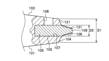
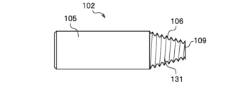
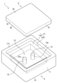
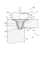
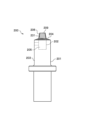
- FIG. 2 is a front view of the rotation tool according to the first embodiment. 2 is a cross-sectional view of a tip portion of a rotation tool according to the first embodiment. FIG. FIG. 2 is a bottom view of the rotation tool according to the first embodiment. FIG. 2 is a front view of a tip side pin member of the rotation tool according to the first embodiment. FIG. 4 is an enlarged cross-sectional view of a first groove in the rotation tool according to the first embodiment. FIG. 2 is an enlarged front view of a tip portion of the rotation tool according to the first embodiment. FIG. 2 is an exploded perspective view of a liquid cooling jacket which is a member to be joined according to the first embodiment.
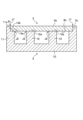
- FIG. 4 is a cross-sectional view showing a placement step in the manufacturing method of the liquid cooling jacket according to the first embodiment.
- FIG. 4 is a cross-sectional view showing a main joining step in the manufacturing method of the liquid cooling jacket according to the first embodiment.
- FIG. 4 is a cross-sectional view showing a main joining step in the manufacturing method of the liquid cooling jacket according to the first embodiment.
- FIG. 11 is a front view of a rotation tool according to a second embodiment.
- FIG. 11 is a cross-sectional view of a tip portion of a rotation tool according to a second embodiment.
- FIG. 11 is an enlarged front view of a tip portion of a rotation tool according to a second embodiment.
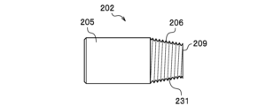
- FIG. 11 is a front view of a tip side pin member of a rotation tool according to a second embodiment.
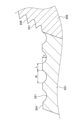
- FIG. 11 is an enlarged cross-sectional view of a first groove in a rotation tool according to a second embodiment.
- FIG. 11 is an enlarged front view of a tip portion of a rotation tool according to a second embodiment.
- FIG. 4 is a diagram showing various parameters of the rotation tool according to the first embodiment.
- FIG. 11 is a diagram showing various parameters of a rotation tool according to a second embodiment.
- 13 is a photograph, shown in place of a drawing, of a welded portion of workpieces welded by the rotary tool according to the third embodiment.
- FIG. 11 is a diagram showing various parameters of a rotation tool according to a third embodiment.
- 13 is a photograph, shown in place of a drawing, of a welded portion of workpieces welded by the rotary tool according to the third embodiment.
- 13 is a photograph, shown in place of a drawing, of a welded portion (flat surface) of workpieces welded by the rotary tool according to the fourth embodiment.
- 13 is a photograph, shown in place of a drawing, of a welded portion (cross section) of workpieces welded by the rotary tool according to the fourth embodiment.
- 1 is a photograph, shown as a substitute for a drawing, of a welded portion (flat surface) of workpieces welded by a rotary tool according to a comparative example.
- 1 is a photograph, shown in place of a drawing, of a welded portion (cross section) of workpieces welded by a rotary tool according to a comparative example.
- the rotation tool is a tool used for friction stirring.
- the rotation tool 100 is formed of, for example, tool steel, and is mainly composed of a base end pin member 101 and a tip end pin member 102.
- the base-end pin member 101 includes a shaft-shaped base shaft portion 103 and a base-end pin 104 extending from the tip side of the base shaft portion 103.
- the base shaft portion 103 has a truncated cone shape and is connected to a main shaft (not shown) of the friction stir device.
- the base-end pin 104 is a portion forming a shoulder portion of the rotating tool 100 and is inclined into a tapered shape.
- the tip side pin member 102 includes an axial base shaft portion 105 and a tip side pin 106 extending from the tip side of the base shaft portion 105.
- the base shaft portion 105 is cylindrical and opens at the tip of the tip side pin member 102, and is stored in a storage portion 107 which is a recess whose inner peripheral shape matches the outer peripheral shape of the base shaft portion 105.
- a storage portion 107 which is a recess whose inner peripheral shape matches the outer peripheral shape of the base shaft portion 105.
- the tip side pin 106 has a tapered shape, and the surface portion is inclined in a tapered shape.
- a screw hole 108 is formed in the base end pin member 101, and a screw is passed through this screw hole to screw the tip end pin member 102 to the base end pin member 101 (the screw is not shown).
- the base end pin 104 and the tip end pin 106 are separate members, but the rotation tool 100 may be manufactured by integrally molding the base end pin 104 and the tip end pin 106.
- the base end pin member 101 and the tip end pin member 102 may be fixed by a method such as fitting, and the fixing method is not limited to screwing.
- the base pin 104 has a truncated cone shape.
- the taper angle A (see FIG. 6) of the base pin 104 may be set as appropriate, but the taper angle A is greater than the taper angle B of the tip pin 106.
- a first groove 121 is formed over the entire outer circumferential surface (shoulder portion) of the base pin 104.
- the first groove 121 is formed in a right-handed or left-handed spiral shape (right-handed or left-handed spiral shape in plan view). In this first embodiment, in order to rotate the rotating tool 100 right, the first groove 121 is set to rotate left from the base side to the tip side.
- the first groove 121 When rotating the rotating tool 100 counterclockwise, it is preferable to set the first groove 121 clockwise from the base end side of the base end pin 104 toward the tip end. This allows the first groove 121 to guide the plastic flow material toward the tip end, thereby reducing the amount of metal spilling out of the joined metal members.
- the tip pin 106 has a truncated cone shape.
- the tip of the tip pin 106 has a flat surface 109 perpendicular to the central axis of rotation.
- the taper angle B (see FIG. 6) of the tip pin 106 is smaller than the taper angle A of the base pin 104.
- a spiral second groove 131 is engraved on the outer circumferential surface of the tip pin 106.
- the second groove 131 is formed in a right-handed or left-handed spiral shape (a right-handed or left-handed spiral shape in a plan view).
- the second groove 131 may be either right-handed or left-handed, but in this first embodiment, in order to rotate the rotating tool 100 right-handed, it is engraved left-handed from the base end side of the tip pin 106 toward the tip side.
- the outer diameter D1 of the base end pin 104 (the outer diameter of the base end of the base end pin 104) and the outer diameter D2 of the tip end pin 106 (the outer diameter of the base end of the tip end pin 106) have a relationship of "1.5 ⁇ D1/D2 ⁇ 3.0".
- the relationship is "1.7 ⁇ D1/D2 ⁇ 2.7”, and more preferably, "1.9 ⁇ D1/D2 ⁇ 2.3".
- the groove width W of the first groove 121 is "1.0 mm ⁇ W ⁇ 2.8 mm” and the wall thickness L of the first groove 121 is "0.1 mm ⁇ L ⁇ 1.8 mm".
- the wall thickness L of the first groove 121 is "0.1 mm ⁇ L ⁇ 1.8 mm.
- “1.1 mm ⁇ W ⁇ 1.6 mm” and “0.2 mm ⁇ L ⁇ 0.5 mm” and more preferably, "1.2 mm ⁇ W ⁇ 1.5 mm” and "0.3 mm ⁇ L ⁇ 0.4 mm”.
- the groove depth Y of the first groove 121 is "0.2 mm ⁇ Y ⁇ 1.0 mm".
- it is "0.2 mm ⁇ Y ⁇ 0.8 mm", and more preferably, it is "0.3 mm ⁇ Y ⁇ 0.5 mm”.
- the number of turns N of the first spiral groove 121 is in the range of 1 ⁇ N ⁇ 5.2. Preferably, it is in the range of 1.4 ⁇ N ⁇ 4.4, and more preferably, it is in the range of 1.7 ⁇ N ⁇ 3.7.
- a friction stir welding process performed using the rotary tool 100 will be described.
- a liquid-cooled jacket is manufactured by friction stir welding, and as shown in Fig. 7 and subsequent figures, a jacket body 2 and a sealing body 3 are used as members to be joined, and the liquid-cooled jacket 1 is manufactured by joining the jacket body 2 and the sealing body 3 by friction stir welding.
- the following example merely shows one example of a friction stir welding process using the rotary tool 100, and the members to be joined by the rotary tool 100 can be various products, and the following example does not limit the present invention.
- the liquid cooling jacket 1 is composed of a jacket body 2 and a sealing body 3.
- the liquid cooling jacket 1 is a device that cools a heat generating body placed inside by circulating a fluid therein.
- the jacket body 2 and the sealing body 3 are integrated by friction stir welding.
- front surface means the surface opposite to the "rear surface.”
- the jacket body 2 may be made of any metal capable of friction stirring (aluminum, aluminum alloy, magnesium, magnesium alloy, copper, copper alloy, titanium, titanium alloy, etc.), but in this first embodiment, it is made of an aluminum alloy.
- the bottom 10 is a rectangular plate-like member.
- the peripheral wall 11 is a wall rising from the periphery of the bottom 10 in the shape of a rectangular frame.
- Support pillars 12 rise from the bottom 10. There is no particular limit to the number of support pillars 12, but in this embodiment there are two.
- the bottom 10 and the peripheral wall 11 form a recess 13. Note that although the jacket body 2 in this embodiment is integrally formed, for example, the peripheral wall 11 may be divided and joined together with a sealing member to form an integral structure.
- the support pillars 12 may also be omitted.
- a peripheral wall step 14 is formed along the inner peripheral edge of the peripheral wall 11 of the jacket body 2 on the end face 11a which is the end face of the peripheral wall 11.
- the peripheral wall step 14 is composed of a step bottom face 14a and a step side face 14b rising from the step bottom face 14a.
- the step bottom face 14a is formed at a position one step lower than the end face 11a.
- the step bottom face 14a is at the same height as the end face 12a of the support 12.
- the sealing body 3 is a plate-like member that seals the opening of the jacket body 2.
- the thickness of the side surface 3c of the sealing body 3 may be the same as the height of the step side surface 14b, or may be greater than the height of the step side surface 14b.
- the sealing body 3 is not particularly limited as long as it is a metal capable of friction stirring, but in this embodiment it is formed of an aluminum alloy.
- the preparation step is a step of preparing the jacket body 2 and the sealing body 3.
- the jacket body 2 is molded by, for example, die casting, and the sealing body 3 is molded by, for example, extrusion molding.
- the placement process is a process of placing the sealing body 3 on the peripheral wall step portion 14 formed in the jacket main body 2, as shown in FIG. 8.
- the step side surface 14b of the peripheral wall step portion 14 and the side surface 3c of the sealing body 3 are butted together to form a first butt portion J1.
- the step bottom surface 14a of the peripheral wall step portion 14 and the back surface 3b of the sealing body 3 are overlapped to form a second butt portion J2.
- the end surface 12a of the support 12 and the back surface 3b of the sealing body 3 are overlapped to form an overlap portion J3.
- the jacket main body 2 and the sealing body 3 may be temporarily joined by welding, friction stirring, or the like.
- the first joining process is a process of friction stir welding the first butt joint J1 using a rotating tool 100, as shown in FIG. 9. While maintaining the "predetermined depth" and ensuring that the rotation center axis Z of the rotating tool 100 is perpendicular to the end face 11a of the peripheral wall portion 11 and the surface 3a of the sealing body 3, the rotating tool 100 is moved relatively along the first butt joint J1 to go around the jacket body 2 and the sealing body 3.
- the predetermine depth of the rotating tool 100 may be set appropriately.
- a plasticized region U1 is formed in the movement trajectory of the rotating tool 100.
- the base shaft portion 103 of the base pin member 101 is not in contact with the jacket body 2 and the sealing body 3, and a predetermined depth is set so that the entire base pin 104 and the entire tip pin 106 are in contact with the jacket body 2 and the sealing body 3.
- the predetermined depth may also be set so that the end surface 11a of the peripheral wall portion 11 and the surface 3a of the sealing body 3 are in contact with the center of the base pin 104 in the height direction.
- the second main joining process is a process of friction stir welding the sealing body 3 and the support 12 using a rotating tool 100, as shown in FIG. 10.
- the rotating tool 100 is inserted vertically into the surface 3a of the sealing body 3 and moved relatively around one revolution or more along the overlapping portion J3, and then the rotating tool 100 is removed from the sealing body 3.
- a plasticized region U2 is formed on the movement trajectory of the rotating tool 100.
- the predetermined depth of the rotating tool 100 in the second main joining process may be set appropriately, similar to the first main joining process.
- the second main joining process may be omitted.
- the outer diameter D1 of the base pin 104 and the outer diameter D2 of the tip pin 106 have a relationship of "1.5 ⁇ D1/D2 ⁇ 3.0". If D1/D2 is less than 1.5, D1 is too small compared to the outer diameter D2, so the force pushing in the plastic flow material is weak and there is a risk of a joint defect occurring. On the other hand, if D1/D2 exceeds 3.0, the contact area between the base pin 104 and the workpieces becomes large, so that the frictional heat generated becomes excessive.
- the wall thickness L of the first grooves 121 is "0.1 mm ⁇ L ⁇ 1.8 mm", good friction stir welding can be performed.
- the rotation tool is a tool used for friction stirring.
- the rotation tool 200 is formed of, for example, tool steel, and is mainly composed of a base end pin member 201 and a tip end pin member 202.
- the base shaft portion 205 is cylindrical and opens at the tip of the tip side pin member 202, and is stored in a storage portion 207 which is a recess whose inner peripheral shape matches the outer peripheral shape of the base shaft portion 205.
- a storage portion 207 which is a recess whose inner peripheral shape matches the outer peripheral shape of the base shaft portion 205.
- a screw hole 208 is formed in the base end pin member 201, and a screw is passed through this screw hole to screw the tip end pin member 202 to the base end pin member 201 (the screw is not shown).
- the rotation tool 200 may also be manufactured by integrally molding the base end pin 204 and the tip end pin 206.
- the base pin 204 has a truncated cone shape.
- the taper angle A (FIG. 16) of the base pin 204 may be set as appropriate, but the taper angle A is greater than the taper angle B of the tip pin 106.
- a first groove 221 is formed over the entire outer circumferential surface (shoulder portion) of the base pin 204.
- the first groove 221 is formed in a right-handed or left-handed spiral shape (right-handed or left-handed spiral shape in plan view). In this second embodiment, in order to rotate the rotating tool 200 right, the first groove 221 is set to rotate left-handed from the base side to the tip side.
- the tip side pin 206 has a truncated cone shape.
- the tip of the tip side pin 206 has a flat surface 209 perpendicular to the central axis of rotation.
- a groove may be formed in the flat surface 209.
- the taper angle B (FIG. 16) of the tip side pin 206 is smaller than the taper angle A (FIG. 16) of the base side pin 204.
- a spiral second groove 231 is engraved on the outer circumferential surface of the tip side pin 206.
- the second groove 231 is formed in a right-handed or left-handed spiral shape (a right-handed or left-handed spiral shape in a plan view).
- the outer diameter D1 of the base end pin 204 (the outer diameter of the base end of the base end pin 204) and the outer diameter D2 of the tip end pin 206 (the outer diameter of the base end of the tip end pin 206) have a relationship of "1.5 ⁇ D1/D2 ⁇ 3.0".
- the relationship is "1.7 ⁇ D1/D2 ⁇ 2.7”, and more preferably, "1.9 ⁇ D1/D2 ⁇ 2.3".
- the groove width W of the first groove 221 is "1.0 mm ⁇ W ⁇ 2.8 mm” and the wall thickness L of the first groove 221 is "0.1 mm ⁇ L ⁇ 1.8 mm".
- the wall thickness L of the first groove 221 is "0.1 mm ⁇ L ⁇ 1.8 mm.
- “1.1 mm ⁇ W ⁇ 1.6 mm” and “0.2 mm ⁇ L ⁇ 0.5 mm” and more preferably, "1.2 mm ⁇ W ⁇ 1.5 mm” and "0.3 mm ⁇ L ⁇ 0.4 mm”.
- the groove depth Y of the first groove 221 is "0.2 mm ⁇ Y ⁇ 1.0 mm".
- it is "0.4 mm ⁇ Y ⁇ 0.9 mm", and more preferably, it is "0.5 mm ⁇ Y ⁇ 0.8 mm”.
- the number of turns N of the first spiral groove 221 is in the range of 1 ⁇ N ⁇ 5.2. Preferably, it is in the range of 1.5 ⁇ N ⁇ 4.5, and more preferably, it is in the range of 2.0 ⁇ N ⁇ 4.5.
- the difference in configuration between the rotary tool 100 of the first embodiment and the rotary tool 200 of the second embodiment is mainly in the size of each part, as is clear from a comparison of the drawings of both embodiments, but the technical features characteristic of the present invention are almost the same for both.
- the outer diameter D1 of the base pin 204 and the outer diameter D2 of the tip pin 206 have a relationship of "1.5 ⁇ D1/D2 ⁇ 3.0". If D1/D2 is less than 1.5, D1 is too small compared to the outer diameter D2, so the force pushing in the plastic flow material is weak and there is a risk of a joint defect occurring. On the other hand, if D1/D2 exceeds 3.0, the contact area between the base pin 104 and the workpieces becomes large, so that the frictional heat generated becomes excessive.
- the groove width W of the first groove 221 is "1.0 mm ⁇ W ⁇ 2.8 mm"
- the wall thickness L of the first groove 221 is "0.1 mm ⁇ L ⁇ 1.8 mm”. This allows the groove width W and wall thickness L of the first groove 221 to be set to appropriate sizes. That is, if the groove width W exceeds 2.8 mm, the recess of the first groove 221 may become excessively large and the frictional heat may also increase. On the other hand, if the groove width W is less than 1.0 mm, the frictional heat may decrease and the accuracy of the friction stirring may decrease.
- the stirred material that is about to overflow is caused to flow toward the direction of the rotation center axis Z and is accumulated in the base end side pin 204. Therefore, if the groove width W becomes small, the accumulation effect decreases, and surface defects may be easily formed. Furthermore, if the wall thickness L exceeds 1.8 mm, the distance between adjacent first grooves 221, 221 becomes too large, and the friction stir welding function deteriorates. In other words, if the wall thickness L becomes too large, the distance between the first grooves 221, 221 increases, and the effect of the grooves described above (the effect of storing overflowing material) decreases, making surface defects more likely to occur. If the wall thickness L of the first grooves 221 is "0.1 mm ⁇ L ⁇ 1.8 mm", good friction stir welding can be performed.
- the groove depth Y of the first groove 221 is "0.2 mm ⁇ Y ⁇ 1.0 mm". If the groove depth Y of the first groove 221 is less than 0.2 mm, it will not function as a groove. In other words, if the groove depth Y is too small, the effect of the groove (the effect of storing overflowing material) will be reduced, making surface defects more likely to occur. On the other hand, if the groove depth Y exceeds 1.0 mm, the groove will be too deep, making it easier for the plastic flow material to remain in the groove, and there is a risk that the plastic flow material remaining in the groove will damage the members to be joined.
- the rotating tool 200 of this embodiment can perform friction stir welding well by setting the groove depth Y in the above range.
- the number of turns N of the first spiral groove 221 is "1 ⁇ N ⁇ 5.2". This allows the rotating tool 200 to perform good friction stir welding.
- Fig. 17 is a diagram showing various parameters of the rotary tool according to the first embodiment of the present invention.
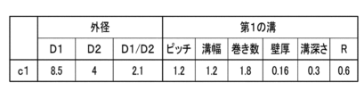
- a total of 10 examples are shown, which are examples a1 to a5 and b1 to b5.
- Examples a1 to a5 are examples of the rotary tool 100.
- Examples b1 to b5 are examples of the rotary tool 200.
- Fig. 20 shows various parameters for the "outer diameter" of the rotary tool and the "first groove” (the first grooves 121, 221) in each of these examples, broadly categorized.
- the “outer diameter” parameters include “D1” (mm), which is the outer diameter D1 of the base end pins 104, 204 (outer diameter of the base end of the base end pins 104, 204), “D2” (mm), which is the outer diameter D2 of the tip end pins 106, 206 (outer diameter of the base end of the tip end pins 106, 206), and the ratio between them, which is the above-mentioned "D1/D2.”
- the parameters of the "first groove” include, for the first groove 121, 221, the “pitch” (mm), which is the pitch, the “groove width” (mm), which is the groove width W mentioned above, the “number of turns” which is the number of turns N mentioned above, the "wall thickness” (mm), which is the wall thickness L mentioned above, the “groove depth” (mm), which is the groove depth Y mentioned above, and the “R” (mm), which is the radius of curvature of the groove.
- Example a1 D1 was 8.5 mm, D2 was 4 mm, D1/D2 was 2.1, pitch was 1.2 mm, groove width was 1.0 mm, number of turns was 1.8, wall thickness was 0.3 mm, groove depth was 0.3 mm, and R was 0.6 mm.
- Example a2 D1 was 8.5 mm, D2 was 3 mm, D1/D2 was 2.8, pitch was 1.2 mm, groove width was 1.0 mm, number of turns was 2.3, wall thickness was 0.3 mm, groove depth was 0.3 mm, and R was 0.6 mm.
- Example a3 D1 was 8.5 mm, D2 was 5 mm, D1/D2 was 1.7, pitch was 1.2 mm, groove width was 1.0 mm, number of turns was 1.4, wall thickness was 0.3 mm, groove depth was 0.3 mm, and R was 0.6 mm.
- Example a4 D1 was 8.5 mm, D2 was 4 mm, D1/D2 was 2.1, pitch was 1.0 mm, groove width was 1.0 mm, number of turns was 2.2, wall thickness was 0.1 mm, groove depth was 0.3 mm, and R was 0.6 mm.
- Example a5 D1 was 8.5 mm, D2 was 4 mm, D1/D2 was 2.1, pitch was 1.5 mm, groove width was 1.0 mm, number of turns was 1.0, wall thickness was 0.6 mm, groove depth was 0.3 mm, and R was 0.6 mm.
- Example b1 D1 was 30 mm, D2 was 14 mm, D1/D2 was 2.1, pitch was 2.0 mm, groove width was 1.4 mm, number of turns was 4.1, wall thickness was 0.7 mm, groove depth was 0.5 mm, and R was 0.75 mm.
- Example b2 D1 was 30 mm, D2 was 10 mm, D1/D2 was 3.0, pitch was 2.0 mm, groove width was 1.4 mm, number of turns was 5.2, wall thickness was 0.7 mm, groove depth was 0.5 mm, and R was 0.75 mm.
- Example b3 D1 was 30 mm, D2 was 18 mm, D1/D2 was 1.7, pitch was 2.0 mm, groove width was 1.4 mm, number of turns was 3.0, wall thickness was 0.7 mm, groove depth was 0.5 mm, and R was 0.75 mm.
- Example b4 D1 was 30 mm, D2 was 14 mm, D1/D2 was 2.1, pitch was 3.0 mm, groove width was 1.4 mm, number of turns was 2.8, wall thickness was 1.8 mm, groove depth was 0.5 mm, and R was 0.75 mm.
- Example b5 D1 was 30 mm, D2 was 14 mm, D1/D2 was 2.1, pitch was 3.5 mm, groove width was 2.8 mm, number of turns was 2.2, wall thickness was 0.9 mm, groove depth was 1.0 mm, and R was 1.5 mm.
- Examples a1 to a5 A5052 (aluminum alloy) and ADC12 (aluminum alloy) were friction stir joined using the rotary tools of the above-mentioned respective Examples.
- Examples b1 to b5 A1050 (aluminum alloy) and C1020 (copper alloy) were friction stir welded using the rotary tools of the above Examples. For each Example, the welded portion was observed to carefully determine whether or not there was a weld defect.
- [Second embodiment] 18 is a diagram showing various parameters of the rotary tool according to the second embodiment of the present invention.
- this second embodiment (embodiment c1), A5052 (aluminum alloy) and ADC12 (aluminum alloy) were used as the workpieces.
- the rotary tool 100 was used, and its rotation speed was 2000 rpm and the welding speed was 750 mm/min.
- D1 was 8.5 mm
- D2 was 4 mm
- D1/D2 was 2.1
- pitch was 1.2 mm
- groove width was 1.2 mm
- number of turns was 1.8
- wall thickness was 0.16 mm
- groove depth was 0.3 mm
- R was 0.6 mm.
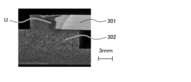
- Figure 19 is a photograph showing an enlarged cut-away section of the joined members of the joined members joined by Example c1.
- the symbol U indicates the plasticized region.
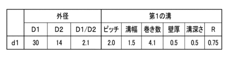
- [Third embodiment] 20 is a diagram showing various parameters of the rotary tool according to the third embodiment of the present invention.
- this third embodiment (embodiment d1), A1050 (aluminum alloy) and C1020 (copper alloy) were used as the workpieces.
- the rotary tool 200 was used, and its rotation speed was 700 rpm and the welding speed was 100 mm/min.
- D1 was 30 mm
- D2 was 14 mm
- D1/D2 was 2.1
- pitch was 2.0 mm
- groove width was 1.5 mm
- number of turns was 4.1
- wall thickness was 0.5 mm
- groove depth was 0.5 mm
- R was 0.75 mm.
- Figure 21 is a photograph showing an enlarged cut-away section of the joined members of the joined members joined by Example d1. As is clear from the photograph, no joint defects were observed in the joint between A1050 (reference number 311) and C1020 (reference number 312), and the joint condition was good. In addition, considering that there was almost no burr in the joint, it can be inferred that frictional heat during friction stirring was also suppressed.
- [Fourth embodiment] 22 and 23 are enlarged photographs of the welded members according to the fourth embodiment.
- A5052 aluminum alloy
- ADC12 aluminum alloy
- the rotating tool 100 was used at a rotation speed of 4000 rpm and a welding speed of 500 mm/min.
- D1 was 8.5 mm
- D2 was 4 mm
- D1/D2 was 2.1
- taper angle A was 130°.
- Figure 22 shows the surface of the welded parts after joining.
- the symbol U indicates the plasticized region.
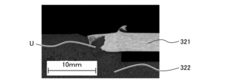
- Figure 23 shows the cross section of the welded parts after joining.
- some burrs were generated in the welded parts, but no welding defects were observed in the joint between A5052 (symbol 321) and ADC12 (symbol 322), and the weld condition was good.
- the amount of burrs discharged was small, it can be inferred that frictional heat during friction stirring was also suppressed.
- [Comparative Example] 24 and 25 are enlarged photographs of welded members according to a comparative example to the above-mentioned examples (particularly the fourth example).
- A5052 aluminum alloy
- ADC12 aluminum alloy
- the rotating tool 100 used had a rotation speed of 4000 rpm and a welding speed of 500 mm/min.
- D1 was 12.5 mm
- D2 was 4 mm
- D1/D2 was 3.1
- taper angle A was 130°.
- Figure 24 shows the surface of the welded parts after joining.
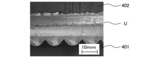
- the symbol U indicates the plasticized region.
- Figure 25 shows a cross section of the welded parts after joining. As shown in the photograph substituted for the same drawing, there is a joint defect at the joint between A5052 (401) and ADC12 (402). It can also be seen that the amount of burrs discharged is large (see Figure 25).
- the groove width W of the first grooves 121, 221 is in the relationship "1.0 mm ⁇ W ⁇ 2.8 mm” and the wall thickness L of the first groove 221 is in the relationship "0.1 mm ⁇ L ⁇ 1.8 mm"
- the amount of heat input to the workpieces during friction stir welding can be set to an appropriate value, and the occurrence of joining defects in the workpieces can be suppressed.
- “1.1 mm ⁇ W ⁇ 1.6 mm” and “0.2 mm ⁇ L ⁇ 0.5 mm” it is believed that joining defects in the workpieces can be reliably suppressed.
- “1.2 mm ⁇ W ⁇ 1.5 mm” and "0.3 mm ⁇ L ⁇ 0.4 mm” it is believed that joining defects in the workpieces can be more reliably suppressed.
- the groove depth Y of the first grooves 121, 221 is "0.2 mm ⁇ Y ⁇ 1.0 mm"
- the amount of heat input to the joined members can be set to an appropriate value, and the occurrence of joining defects in the joined members can be suppressed. It is also believed that if “0.4 mm ⁇ D ⁇ 0.9 mm”, joining defects in the joined members can be suppressed reliably. Furthermore, if “0.5 mm ⁇ D ⁇ 0.8 mm”, joining defects in the joined members can be suppressed even more reliably.
Landscapes
- Engineering & Computer Science (AREA)
- Mechanical Engineering (AREA)
- Pressure Welding/Diffusion-Bonding (AREA)
Abstract
入熱過多になりにくく、接合欠陥の発生を抑制することができる回転ツールを提供する。 摩擦攪拌用の回転ツール(100)は、螺旋状の第1の溝(121)が形成されている基端側ピン(104)と、基端側ピン(104)から延出していて、螺旋状の第2の溝(131)が形成されている先端側ピン(106)と、を備え、基端側ピン(104)のテーパー角度は、先端側ピン(106)のテーパー角度よりも大きく、基端側ピン(104)の外径(D1)と先端側ピン(106)の外径(D2)とは、"1.5≦D1/D2≦3.0"という関係にある。
Description
本発明は、回転ツールに関する。
特許文献1には、摩擦攪拌接合用の回転ツールについて開示されている。この回転ツールは、その肩部がテーパー状に傾斜していて、当該肩部に溝が形成されている。
接合を良好に行うためには、摩擦撹拌接合を行う際に回転ツールと被接合部材の間で発生する摩擦熱を制御することが重要である。
しかしながら、特許文献1のように回転ツールの肩部に螺旋状の溝を設けると、回転ツールによる攪拌力を向上させることができる一方で、被接合部材の表面に発生する摩擦熱が過多になり、接合欠陥が発生しやすくなるという問題がある。
しかしながら、特許文献1のように回転ツールの肩部に螺旋状の溝を設けると、回転ツールによる攪拌力を向上させることができる一方で、被接合部材の表面に発生する摩擦熱が過多になり、接合欠陥が発生しやすくなるという問題がある。
このような観点から、本発明は、回転ツールの肩部に螺旋状の溝を設けても、入熱過多になりにくく、接合欠陥の発生を抑制することができる回転ツールを提供することを課題とする。
前記課題を解決するために、本発明は、螺旋状の第1の溝が形成されている基端側ピンと、前記基端側ピンから延出していて、螺旋状の第2の溝が形成されている先端側ピンと、備えた摩擦攪拌用の回転ツールであって、前記基端側ピンのテーパー角度は、前記先端側ピンのテーパー角度よりも大きく、前記基端側ピンの外径D1と前記先端側ピンの外径D2とは、1.5≦D1/D2≦3.0という関係にあることを特徴とする。
前記第1の溝の溝幅Wは、1.0mm≦W≦2.8mmであり、前記第1の溝の壁厚Lは、0.1mm≦L≦1.8mmであることが好ましい。
前記第1の溝の溝深さYは、0.2mm≦Y≦1.0mmであることが好ましい。
前記第1の溝の巻き数Nは、1≦N≦5.2であることが好ましい。
本発明によれば、回転ツールの肩部に螺旋状の溝を設けても、入熱過多になりにくく、接合欠陥の発生を抑制することができる回転ツールを提供することができる。
本発明の実施形態について、適宜図面を参照しながら説明する。本発明は以下の実施形態のみに限定されるものではない。また、各実施形態における構成要素は一部又は全部を適宜組み合わせることができる。
[第一実施形態]
<回転ツールの構成>
まずは、第一実施形態に係る回転ツールの構成について図1~図6を参照して説明する。回転ツールは、摩擦攪拌に用いられるツールである。回転ツール100は、例えば工具鋼で形成されており、基端側ピン部材101と、先端側ピン部材102とで主に構成されている。
<回転ツールの構成>
まずは、第一実施形態に係る回転ツールの構成について図1~図6を参照して説明する。回転ツールは、摩擦攪拌に用いられるツールである。回転ツール100は、例えば工具鋼で形成されており、基端側ピン部材101と、先端側ピン部材102とで主に構成されている。
基端側ピン部材101は、軸状の基軸部103と、基軸部103の先端側から延出している基端側ピン104とを備えている。基軸部103は、円錐台形状を呈し、摩擦攪拌装置の主軸(図示せず)に接続される部位である。基端側ピン104は、回転ツール100のショルダ部をなす部位であり、テーパー形状に傾斜している。
先端側ピン部材102は、軸状の基軸部105と、基軸部105の先端側から延出している先端側ピン106とを備えている。基軸部105は、円柱状を呈していて、先端側ピン部材102の先端部に開口し、その内周面形状が基軸部105の外周面形状に合っている凹部である収納部107に収納される。収納部107に基軸部105を収納したときは、先端側ピン106のみが外部に露出した状態となる。先端側ピン106は、先細り形状をしていて、表面部がテーパー形状に傾斜している。
先端側ピン部材102は、軸状の基軸部105と、基軸部105の先端側から延出している先端側ピン106とを備えている。基軸部105は、円柱状を呈していて、先端側ピン部材102の先端部に開口し、その内周面形状が基軸部105の外周面形状に合っている凹部である収納部107に収納される。収納部107に基軸部105を収納したときは、先端側ピン106のみが外部に露出した状態となる。先端側ピン106は、先細り形状をしていて、表面部がテーパー形状に傾斜している。
基端側ピン部材101には、ねじ孔108が形成されていて、このねじ穴にねじを通して基端側ピン部材101に対して先端側ピン部材102がねじ留め固定されている(このねじについては図示省略)。なお、本第一実施形態で例示するのは、基端側ピン104と先端側ピン106とが別部材の場合であるが、基端側ピン104と先端側ピン106とを一体成形して回転ツール100を製造してもよい。また、基端側ピン部材101と先端側ピン部材102は篏合等の方法で固定しても良く、固定の方法はねじ止めに限られるものではない。
基端側ピン104は、円錐台形状を呈する。基端側ピン104のテーパー角度A(図6参照)は適宜設定すればよいが、テーパー角度Aは、先端側ピン106のテーパー角度Bよりも大きくなっている。基端側ピン104の外周面(ショルダ部)には、第1の溝121が全体に亘って形成されている。第1の溝121は、右回り又は左回りの螺旋状(平面視して右回り又は左回りの渦巻状)に形成されている。本第一実施形態では、回転ツール100を右回転させるため、第1の溝121は基端側から先端側に向けて左回りに設定している。
なお、回転ツール100を左回転させる場合は、第1の溝121を基端側ピン104の基端側から先端側に向けて右回りに設定することが好ましい。これにより、第1の溝121によって塑性流動材が先端側に導かれるため、被接合金属部材の外部に溢れ出る金属を低減することができる。
先端側ピン106は円錐台形状を呈する。先端側ピン106の先端は回転中心軸線に対して垂直な平坦面109になっている。先端側ピン106のテーパー角度B(図6参照)は、基端側ピン104のテーパー角度Aよりも小さくなっている。先端側ピン106の外周面には、螺旋状の第2の溝131が刻設されている。第2の溝131は、右回り又は左回りの螺旋状(平面視して右回り又は左回りの渦巻状)に形成されている。第2の溝131は、右回り、左回りのどちらでもよいが、本第一実施形態では回転ツール100を右回転させるため、先端側ピン106の基端側から先端側に向けて左回りに刻設されている。
図2に示すように、基端側ピン104の外径D1(基端側ピン104の基端部の外径)と、先端側ピン106の外径D2(先端側ピン106の基端部の外径)とは、“1.5≦D1/D2≦3.0”という関係にある。なお、好ましくは“1.7≦D1/D2≦2.7”、より好ましくは“1.9≦D1/D2≦2.3”である。
図5に示すように、第1の溝121の溝幅Wは、“1.0mm≦W≦2.8mm”であり、第1の溝121の壁厚Lは、“0.1mm≦L≦1.8mm”である。なお、好ましくは、“1.1mm≦W≦1.6mm”且つ“0.2mm≦L≦0.5mm”、より好ましくは、“1.2mm≦W≦1.5mm”且つ“0.3mm≦L≦0.4mm”である。
図5に示すように、第1の溝121の溝深さYは、“0.2mm≦Y≦1.0mm”である。なお、好ましくは“0.2mm≦Y≦0.8mm”、より好ましくは“0.3mm≦Y≦0.5mm”である。
また、螺旋状の第1の溝121の巻き数Nは、“1≦N≦5.2”である。なお、好ましくは“1.4≦N≦4.4”、より好ましくは“1.7≦N≦3.7”である。
<摩擦攪拌接合工程>
次に、回転ツール100を用いて行う摩擦攪拌接合工程について説明する。以下の例で、摩擦攪拌接合により製造するのは液冷ジャケットであり、図7以下に示すように、ジャケット本体2と封止体3とを被接合部材として、ジャケット本体2と封止体3とを摩擦攪拌接合により接合して液冷ジャケット1を製造しようとする例である。なお、以下の例は、回転ツール100による摩擦攪拌接合工程の一例を示すに過ぎず、回転ツール100による接合の対象となる被接合部材は様々な製品とすることができ、以下の例は本発明を限定するものではない。
次に、回転ツール100を用いて行う摩擦攪拌接合工程について説明する。以下の例で、摩擦攪拌接合により製造するのは液冷ジャケットであり、図7以下に示すように、ジャケット本体2と封止体3とを被接合部材として、ジャケット本体2と封止体3とを摩擦攪拌接合により接合して液冷ジャケット1を製造しようとする例である。なお、以下の例は、回転ツール100による摩擦攪拌接合工程の一例を示すに過ぎず、回転ツール100による接合の対象となる被接合部材は様々な製品とすることができ、以下の例は本発明を限定するものではない。
液冷ジャケット1は、図7に示すように、ジャケット本体2と封止体3とで構成されている。液冷ジャケット1は、内部に流体を流通させて、配置される発熱体を冷却する機器である。ジャケット本体2と封止体3とは摩擦攪拌接合で一体化される。以下の説明における「表面」とは、「裏面」の反対側の面を意味する。
ジャケット本体2は、摩擦攪拌可能な金属(アルミニウム、アルミニウム合金、マグネシウム、マグネシウム合金、銅、銅合金、チタン、チタン合金等)であればよいが、本第一実施形態の例ではアルミニウム合金で形成されている。
ジャケット本体2は、摩擦攪拌可能な金属(アルミニウム、アルミニウム合金、マグネシウム、マグネシウム合金、銅、銅合金、チタン、チタン合金等)であればよいが、本第一実施形態の例ではアルミニウム合金で形成されている。
底部10は、矩形を呈する板状部材である。周壁部11は、底部10の周縁部から矩形枠状に立ち上がる壁部である。底部10には、支柱12が立ち上がっている。支柱12の本数は特に制限されないが、本実施形態では2本になっている。底部10及び周壁部11で凹部13が形成されている。なお、本実施形態のジャケット本体2は一体形成されているが、例えば、周壁部11を分割構成としてシール部材で接合して一体化してもよい。また、支柱12は省略してもよい。
周壁部11の端面となる端面11aには、ジャケット本体2の周壁部11の内周縁に沿って周壁段差部14が形成される。周壁段差部14は、段差底面14aと、段差底面14aから立ち上がる段差側面14bとで構成される。段差底面14aは、端面11aから一段下がった位置に形成されている。段差底面14aは、支柱12の端面12aと同じ高さになっている。
封止体3は、ジャケット本体2の開口部を封止する板状部材である。封止体3の側面3cの厚さは、段差側面14bの高さと同一寸法でもよいし、段差側面14bよりも大きくしてもよい。封止体3は、摩擦攪拌可能な金属であれば特に制限されないが、本実施形態ではアルミニウム合金で形成されている。
封止体3は、ジャケット本体2の開口部を封止する板状部材である。封止体3の側面3cの厚さは、段差側面14bの高さと同一寸法でもよいし、段差側面14bよりも大きくしてもよい。封止体3は、摩擦攪拌可能な金属であれば特に制限されないが、本実施形態ではアルミニウム合金で形成されている。
次に、本第一実施形態に係る液冷ジャケットの製造方法について説明する。本第一実施形態に係る液冷ジャケットの製造方法では、準備工程と、載置工程と、第一本接合工程と、第二本接合工程と、を行う。
準備工程は、ジャケット本体2及び封止体3を準備する工程である。ジャケット本体2及び封止体3は、製造方法については特に制限されないが、ジャケット本体2は、例えば、ダイキャストで成形する。封止体3は、例えば押出成形により成形する。
準備工程は、ジャケット本体2及び封止体3を準備する工程である。ジャケット本体2及び封止体3は、製造方法については特に制限されないが、ジャケット本体2は、例えば、ダイキャストで成形する。封止体3は、例えば押出成形により成形する。
載置工程は、図8に示すように、ジャケット本体2に形成される周壁段差部14に、封止体3を載置する工程である。周壁段差部14の段差側面14bと、封止体3の側面3cとが突き合わされて第一突合せ部J1が形成される。さらに、周壁段差部14の段差底面14aと、封止体3の裏面3bとが重ね合わされて第二突合せ部J2が形成される。また、支柱12の端面12aと、封止体3の裏面3bとが重ね合わされて重ね部J3が形成される。なお、ジャケット本体2と封止体3とは溶接又は摩擦攪拌等により仮接合してもよい。
第一本接合工程は、図9に示すように、回転ツール100を用いて第一突合せ部J1を摩擦攪拌接合する工程である。回転ツール100の回転中心軸線Zと周壁部11の端面11a及び封止体3の表面3aとが垂直となるようにしつつ、「所定の深さ」を維持した状態で、回転ツール100を第一突合せ部J1に沿って相対移動させてジャケット本体2及び封止体3の廻りを一周させる。回転ツール100の所定の深さについては、適宜設定すればよい。第一本接合工程において、回転ツール100の移動軌跡には塑性化領域U1が形成される。
本実施形態では、基端側ピン部材101の基軸部103はジャケット本体2及び封止体3に接触させず、かつ、基端側ピン104及び先端側ピン106の全体がジャケット本体2及び封止体3に接触するように所定の深さを設定している。また、周壁部11の端面11a及び封止体3の表面3aと基端側ピン104の高さ方向の真ん中あたりが接触するように所定の深さを設定してもよい。
第二本接合工程は、図10に示すように、回転ツール100を用いて封止体3と支柱12とを摩擦攪拌接合する工程である。第二本接合工程では、回転ツール100を封止体3の表面3aから垂直に挿入し、重ね部J3に沿って一周以上相対移動させた後、封止体3から回転ツール100を離脱させる。第二本接合工程において、回転ツール100の移動軌跡には塑性化領域U2が形成される。第二本接合工程の回転ツール100の所定の深さについては、第一本接合工程と同様に適宜設定すればよい。なお、第二本接合工程は省略してもよい。
<作用効果>
以上説明した第一実施形態に係る回転ツール100によれば、次のような作用効果を奏することができる。
前記のとおり、回転ツール100は、基端側ピン104の外径D1と、先端側ピン106の外径D2とは、“1.5≦D1/D2≦3.0”という関係にある。ここで、D1/D2が1.5未満であると、外径D2に対してD1が小さすぎるため、塑性流動材を押し込む力が弱く、接合欠陥が発生するおそれがある。一方、D1/D2が3.0を超えると基端側ピン104と被接合部材との接触面積が大きくなるため、発生する摩擦熱が過大なものとなる。
これに対し、本実施形態のように基端側ピン104(ショルダ部)に第1の溝121を備え、かつ、基端側ピン104の外径D1と先端側ピン106の外径D2を、“1.5≦D1/D2≦3.0”の関係とすることで、回転ツール100の被接合部材への押込み量が増大しても摩擦熱の発生を抑制できる。そして、これにより、被接合部材の接合部の接合欠陥の発生を抑制することができる。
以上説明した第一実施形態に係る回転ツール100によれば、次のような作用効果を奏することができる。
前記のとおり、回転ツール100は、基端側ピン104の外径D1と、先端側ピン106の外径D2とは、“1.5≦D1/D2≦3.0”という関係にある。ここで、D1/D2が1.5未満であると、外径D2に対してD1が小さすぎるため、塑性流動材を押し込む力が弱く、接合欠陥が発生するおそれがある。一方、D1/D2が3.0を超えると基端側ピン104と被接合部材との接触面積が大きくなるため、発生する摩擦熱が過大なものとなる。
これに対し、本実施形態のように基端側ピン104(ショルダ部)に第1の溝121を備え、かつ、基端側ピン104の外径D1と先端側ピン106の外径D2を、“1.5≦D1/D2≦3.0”の関係とすることで、回転ツール100の被接合部材への押込み量が増大しても摩擦熱の発生を抑制できる。そして、これにより、被接合部材の接合部の接合欠陥の発生を抑制することができる。
また、第1の溝121の溝幅Wは、“1.0mm≦W≦2.8mm”であり、第1の溝121の壁厚Lは、“0.1mm≦L≦1.8mm”である。これにより、第1の溝121の溝幅Wと壁厚Lをそれぞれ適正なサイズに設定することができる。すなわち、溝幅Wが2.8mmを超えると、第1の溝121の凹部が過大なサイズとなり摩擦熱も大きくなることで接合欠陥が発生するおそれがある。一方、溝幅Wが1.0mm未満であると摩擦熱が小さくなり摩擦攪拌の精度が低くなるおそれがある。第1の溝121のようなスクロール溝の溝幅Wの寸法を上記の範囲で形成することで、溢れ出そうとする攪拌された材料を回転中心軸線Z方向に向かって流動させ、基端側ピン104に溜め込む効果がある。そのため、溝幅Wが小さくなると溜め込む効果が減少して、表面欠陥ができやすくなるおそれがある。
また、壁厚Lが1.8mmを超えると、隣り合う第1の溝121,121間が大きくなり過ぎて摩擦攪拌の機能が低下する。つまり、壁厚Lが大きくなり過ぎると、第1の溝121,121の間の距離が広がることにより、上記のような溝の効果(溢れる材料を溜め込む効果)が減ることで表面欠陥が発生しやすくなる。第1の溝121の壁厚Lが、“0.1mm≦L≦1.8mm”であると良好な摩擦攪拌接合を行うことができる。
また、壁厚Lが1.8mmを超えると、隣り合う第1の溝121,121間が大きくなり過ぎて摩擦攪拌の機能が低下する。つまり、壁厚Lが大きくなり過ぎると、第1の溝121,121の間の距離が広がることにより、上記のような溝の効果(溢れる材料を溜め込む効果)が減ることで表面欠陥が発生しやすくなる。第1の溝121の壁厚Lが、“0.1mm≦L≦1.8mm”であると良好な摩擦攪拌接合を行うことができる。
また、第1の溝121の溝深さYは、“0.2mm≦Y≦1.0mm”である。第1の溝121の溝深さYが0.2mm未満であると溝としての機能を果たさなくなる。つまり、溝深さYが小さ過ぎると、溝の効果(溢れる材料を溜め込む効果)が減ることで表面欠陥が発生しやすくなる。一方、溝深さYが1.0mmを超えると溝が深くなりすぎて、溝内に塑性流動材が滞留しやすくなり、溝内に滞留した塑性流動材で被接合部材が損傷するおそれがある。本実施形態の回転ツール100は、溝深さYを上記の範囲に設定することによって良好に摩擦攪拌接合を行うことができる。
また、螺旋状の第1の溝121の巻き数Nは、“1≦N≦5.2”である。これにより、回転ツール100によって良好な摩擦攪拌接合を行うことができる。
[第二実施形態]
<回転ツールの構成>
まずは、第二実施形態に係る回転ツールの構成について図11~図16を参照して説明する。回転ツールは、摩擦攪拌に用いられるツールである。回転ツール200は、例えば工具鋼で形成されており、基端側ピン部材201と、先端側ピン部材202とで主に構成されている。
<回転ツールの構成>
まずは、第二実施形態に係る回転ツールの構成について図11~図16を参照して説明する。回転ツールは、摩擦攪拌に用いられるツールである。回転ツール200は、例えば工具鋼で形成されており、基端側ピン部材201と、先端側ピン部材202とで主に構成されている。
基端側ピン部材201は、軸状の基軸部203と、基軸部203の先端側から延出している基端側ピン204とを備えている。基軸部203は、円柱状を呈し、摩擦攪拌装置の主軸(図示せず)に接続される部位である。基端側ピン204は、回転ツール200のショルダ部をなす部位であり、テーパー形状に傾斜している。
先端側ピン部材202は、軸状の基軸部205と、基軸部205の先端側から延出している先端側ピン206とを備えている。基軸部205は、円柱状を呈していて、先端側ピン部材202の先端部に開口し、その内周面形状が基軸部205の外周面形状に合っている凹部である収納部207に収納される。収納部207に基軸部205を収納したときは、先端側ピン206のみが外部に露出した状態となる。先端側ピン206は、先細り形状をしていて、表面部がテーパー形状に傾斜している。
先端側ピン部材202は、軸状の基軸部205と、基軸部205の先端側から延出している先端側ピン206とを備えている。基軸部205は、円柱状を呈していて、先端側ピン部材202の先端部に開口し、その内周面形状が基軸部205の外周面形状に合っている凹部である収納部207に収納される。収納部207に基軸部205を収納したときは、先端側ピン206のみが外部に露出した状態となる。先端側ピン206は、先細り形状をしていて、表面部がテーパー形状に傾斜している。
基端側ピン部材201には、ねじ孔208が形成されていて、このねじ穴にねじを通して基端側ピン部材201に対して先端側ピン部材202がねじ留め固定されている(このねじについては図示省略)。なお、本第二実施形態で例示するのは、基端側ピン204と先端側ピン206とが別部材の場合であるが、基端側ピン204と先端側ピン206とを一体成形して回転ツール200を製造してもよい。
基端側ピン204は、円錐台形状を呈する。基端側ピン204のテーパー角度A(図16)は適宜設定すればよいが、テーパー角度Aは、先端側ピン106のテーパー角度Bよりも大きくなっている。基端側ピン204の外周面(ショルダ部)には、第1の溝221が全体に亘って形成されている。第1の溝221は、右回り又は左回りの螺旋状(平面視して右回り又は左回りの渦巻状)に形成されている。本第二実施形態では、回転ツール200を右回転させるため、第1の溝221は基端側から先端側に向けて左回りに設定している。
なお、回転ツール200を左回転させる場合は、第1の溝221を基端側ピン204の基端側から先端側に向けて右回りに設定することが好ましい。これにより、第1の溝221によって塑性流動材が先端側に導かれるため、被接合金属部材の外部に溢れ出る金属を低減することができる。
先端側ピン206は円錐台形状を呈する。先端側ピン206の先端は回転中心軸線に対して垂直な平坦面209になっている。平坦面209に溝を形成してもよい。先端側ピン206のテーパー角度B(図16)は、基端側ピン204のテーパー角度A(図16)よりも小さくなっている。先端側ピン206の外周面には、螺旋状の第2の溝231が刻設されている。第2の溝231は、右回り又は左回りの螺旋状(平面視して右回り又は左回りの渦巻状)に形成されている。
先端側ピン206は円錐台形状を呈する。先端側ピン206の先端は回転中心軸線に対して垂直な平坦面209になっている。平坦面209に溝を形成してもよい。先端側ピン206のテーパー角度B(図16)は、基端側ピン204のテーパー角度A(図16)よりも小さくなっている。先端側ピン206の外周面には、螺旋状の第2の溝231が刻設されている。第2の溝231は、右回り又は左回りの螺旋状(平面視して右回り又は左回りの渦巻状)に形成されている。
図12に示すように、基端側ピン204の外径D1(基端側ピン204の基端部の外径)と、先端側ピン206の外径D2(先端側ピン206の基端部の外径)とは、“1.5≦D1/D2≦3.0”という関係にある。なお、好ましくは“1.7≦D1/D2≦2.7”、より好ましくは“1.9≦D1/D2≦2.3”である。
図15に示すように、第1の溝221の溝幅Wは、“1.0mm≦W≦2.8mm”であり、第1の溝221の壁厚Lは、“0.1mm≦L≦1.8mm”である。なお、好ましくは、“1.1mm≦W≦1.6mm”且つ“0.2mm≦L≦0.5mm”、より好ましくは、“1.2mm≦W≦1.5mm”且つ“0.3mm≦L≦0.4mm”である。
図15に示すように、第1の溝221の溝深さYは、“0.2mm≦Y≦1.0mm”である。なお、好ましくは“0.4mm≦Y≦0.9mm”、より好ましくは“0.5mm≦Y≦0.8mm”である。
また、螺旋状の第1の溝221の巻き数Nは、“1≦N≦5.2”である。なお、好ましくは“1.5≦N≦4.5”、より好ましくは“2.0≦N≦4.5”である。
第一実施形態の回転ツール100と、本第二実施形態の回転ツール200との構成上の相違は、両実施形態の図面を比較すれば明らかなように、主に各部のサイズの違いにあり、本発明に特徴的な技術事項は両者ほぼ共通である。
<摩擦攪拌接合工程>
本第二実施形態の摩擦攪拌接合工程は、前記した第一実施形態の場合と同様であるため、詳細な説明は省略する。
本第二実施形態の摩擦攪拌接合工程は、前記した第一実施形態の場合と同様であるため、詳細な説明は省略する。
<作用効果>
以上説明した第二実施形態に係る回転ツール200によれば、次のような作用効果を奏することができる。
前記のとおり、回転ツール200は、基端側ピン204の外径D1と、先端側ピン206の外径D2とは、“1.5≦D1/D2≦3.0”という関係にある。ここで、D1/D2が1.5未満であると、外径D2に対してD1が小さすぎるため、塑性流動材を押し込む力が弱く、接合欠陥が発生するおそれがある。一方、D1/D2が3.0を超えると基端側ピン104と被接合部材との接触面積が大きくなるため、発生する摩擦熱が過大なものとなる。
これに対し、本実施形態のように基端側ピン204(ショルダ部)に第1の溝221を備え、かつ、基端側ピン204の外径D1と先端側ピン106の外径D2を、“1.5≦D1/D2≦3.0”の関係とすることで、回転ツール200の被接合部材への押込み量が増大しても摩擦熱の発生を抑制できる。そして、これにより、被接合部材の接合部の接合欠陥の発生を抑制することができる。
以上説明した第二実施形態に係る回転ツール200によれば、次のような作用効果を奏することができる。
前記のとおり、回転ツール200は、基端側ピン204の外径D1と、先端側ピン206の外径D2とは、“1.5≦D1/D2≦3.0”という関係にある。ここで、D1/D2が1.5未満であると、外径D2に対してD1が小さすぎるため、塑性流動材を押し込む力が弱く、接合欠陥が発生するおそれがある。一方、D1/D2が3.0を超えると基端側ピン104と被接合部材との接触面積が大きくなるため、発生する摩擦熱が過大なものとなる。
これに対し、本実施形態のように基端側ピン204(ショルダ部)に第1の溝221を備え、かつ、基端側ピン204の外径D1と先端側ピン106の外径D2を、“1.5≦D1/D2≦3.0”の関係とすることで、回転ツール200の被接合部材への押込み量が増大しても摩擦熱の発生を抑制できる。そして、これにより、被接合部材の接合部の接合欠陥の発生を抑制することができる。
また、第1の溝221の溝幅Wは、“1.0mm≦W≦2.8mm”であり、第1の溝221の壁厚Lは、“0.1mm≦L≦1.8mm”である。これにより、第1の溝221の溝幅Wと壁厚Lをそれぞれ適正なサイズに設定することができる。すなわち、溝幅Wが2.8mmを超えると、第1の溝221の凹部が過大なサイズとなり摩擦熱も大きくなるおそれがある。一方、溝幅Wが1.0mm未満であると摩擦熱が小さくなり摩擦攪拌の精度が低くなるおそれがある。第1の溝221のようなスクロール溝の溝幅Wの寸法を上記の範囲で形成することで、溢れ出そうとする攪拌された材料を回転中心軸線Z方向に向かって流動させ、基端側ピン204に溜め込む効果がある。そのため、溝幅Wが小さくなると溜め込む効果が減少して、表面欠陥ができやすくなるおそれがある。
また、壁厚Lが1.8mmを超えると、隣り合う第1の溝221,221間が大きくなり過ぎて摩擦攪拌の機能が低下する。つまり、壁厚Lが大きくなり過ぎると、第1の溝221,221の間の距離が広がることにより、上記のような溝の効果(溢れる材料を溜め込む効果)が減ることで表面欠陥が発生しやすくなる。第1の溝221の壁厚Lが、“0.1mm≦L≦1.8mm”であると良好な摩擦攪拌接合を行うことができる。
また、壁厚Lが1.8mmを超えると、隣り合う第1の溝221,221間が大きくなり過ぎて摩擦攪拌の機能が低下する。つまり、壁厚Lが大きくなり過ぎると、第1の溝221,221の間の距離が広がることにより、上記のような溝の効果(溢れる材料を溜め込む効果)が減ることで表面欠陥が発生しやすくなる。第1の溝221の壁厚Lが、“0.1mm≦L≦1.8mm”であると良好な摩擦攪拌接合を行うことができる。
また、第1の溝221の溝深さYは、“0.2mm≦Y≦1.0mm”である。第1の溝221の溝深さYが0.2mm未満であると溝としての機能を果たさなくなる。つまり、溝深さYが小さ過ぎると、溝の効果(溢れる材料を溜め込む効果)が減ることで表面欠陥が発生しやすくなる。一方、溝深さYが1.0mmを超えると溝が深くなりすぎて、溝内に塑性流動材が滞留しやすくなり、溝内に滞留した塑性流動材で被接合部材が損傷するおそれがある。本実施形態の回転ツール200は、溝深さYを上記の範囲に設定することによって良好に摩擦攪拌接合を行うことができる。
また、螺旋状の第1の溝221の巻き数Nは、“1≦N≦5.2”である。これにより、回転ツール200によって良好な摩擦攪拌接合を行うことができる。
以下に、本発明に係る実施例を複数例と、それに対する比較例を複数例示す。本発明は以下の実施例に限定されるものではない。
[第一実施例]
図17は、本発明の第一実施例に係る回転ツールの各種パラメータを示す図である。ここでは、実施例a1~a5,b1~b5の合計10例の実施例を示している。実施例a1~a5は、前記回転ツール100の実施例である。実施例b1~b5は、前記回転ツール200の実施例である。図20では、これらの各実施例において、大別して回転ツールの「外径」と、「第1の溝」(前記第1の溝121,221)とについて各種パラメータを示している。
図17は、本発明の第一実施例に係る回転ツールの各種パラメータを示す図である。ここでは、実施例a1~a5,b1~b5の合計10例の実施例を示している。実施例a1~a5は、前記回転ツール100の実施例である。実施例b1~b5は、前記回転ツール200の実施例である。図20では、これらの各実施例において、大別して回転ツールの「外径」と、「第1の溝」(前記第1の溝121,221)とについて各種パラメータを示している。
「外径」のパラメータとしては、前記した基端側ピン104,204の外径D1(基端側ピン104,204の基端部の外径)である「D1」(mm)と、前記した先端側ピン106,206の外径D2(先端側ピン106,206の基端部の外径)である「D2」(mm)と、これらの比率である前記した「D1/D2」とを示している。
「第1の溝」のパラメータとしては、第1の溝121,221に関して、そのピッチである「ピッチ」(mm)、前記した溝幅Wである「溝幅」(mm)、前記した巻き数Nである「巻き数」、前記した壁厚Lである「壁厚」(mm)、前記した溝深さYである「溝深さ」(mm)、溝の曲率半径である「R」(mm)を示している。
「第1の溝」のパラメータとしては、第1の溝121,221に関して、そのピッチである「ピッチ」(mm)、前記した溝幅Wである「溝幅」(mm)、前記した巻き数Nである「巻き数」、前記した壁厚Lである「壁厚」(mm)、前記した溝深さYである「溝深さ」(mm)、溝の曲率半径である「R」(mm)を示している。
実施例a1は、D1が8.5mm、D2が4mm、D1/D2が2.1、ピッチが1.2mm、溝幅が1.0mm、巻き数が1.8、壁厚が0.3mm、溝深さが0.3mm、Rが0.6mm、であった。
実施例a2は、D1が8.5mm、D2が3mm、D1/D2が2.8、ピッチが1.2mm、溝幅が1.0mm、巻き数が2.3、壁厚が0.3mm、溝深さが0.3mm、Rが0.6mm、であった。
実施例a2は、D1が8.5mm、D2が3mm、D1/D2が2.8、ピッチが1.2mm、溝幅が1.0mm、巻き数が2.3、壁厚が0.3mm、溝深さが0.3mm、Rが0.6mm、であった。
実施例a3は、D1が8.5mm、D2が5mm、D1/D2が1.7、ピッチが1.2mm、溝幅が1.0mm、巻き数が1.4、壁厚が0.3mm、溝深さが0.3mm、Rが0.6mm、であった。
実施例a4は、D1が8.5mm、D2が4mm、D1/D2が2.1、ピッチが1.0mm、溝幅が1.0mm、巻き数が2.2、壁厚が0.1mm、溝深さが0.3mm、Rが0.6mm、であった。
実施例a4は、D1が8.5mm、D2が4mm、D1/D2が2.1、ピッチが1.0mm、溝幅が1.0mm、巻き数が2.2、壁厚が0.1mm、溝深さが0.3mm、Rが0.6mm、であった。
実施例a5は、D1が8.5mm、D2が4mm、D1/D2が2.1、ピッチが1.5mm、溝幅が1.0mm、巻き数が1.0、壁厚が0.6mm、溝深さが0.3mm、Rが0.6mm、であった。
実施例b1は、D1が30mm、D2が14mm、D1/D2が2.1、ピッチが2.0mm、溝幅が1.4mm、巻き数が4.1、壁厚が0.7mm、溝深さが0.5mm、Rが0.75mm、であった。
実施例b1は、D1が30mm、D2が14mm、D1/D2が2.1、ピッチが2.0mm、溝幅が1.4mm、巻き数が4.1、壁厚が0.7mm、溝深さが0.5mm、Rが0.75mm、であった。
実施例b2は、D1が30mm、D2が10mm、D1/D2が3.0、ピッチが2.0mm、溝幅が1.4mm、巻き数が5.2、壁厚が0.7mm、溝深さが0.5mm、Rが0.75mm、であった。
実施例b3は、D1が30mm、D2が18mm、D1/D2が1.7、ピッチが2.0mm、溝幅が1.4mm、巻き数が3.0、壁厚が0.7mm、溝深さが0.5mm、Rが0.75mm、であった。
実施例b3は、D1が30mm、D2が18mm、D1/D2が1.7、ピッチが2.0mm、溝幅が1.4mm、巻き数が3.0、壁厚が0.7mm、溝深さが0.5mm、Rが0.75mm、であった。
実施例b4は、D1が30mm、D2が14mm、D1/D2が2.1、ピッチが3.0mm、溝幅が1.4mm、巻き数は2.8、壁厚が1.8mm、溝深さが0.5mm、Rが0.75mm、であった。
実施例b5は、D1が30mm、D2が14mm、D1/D2が2.1、ピッチが3.5mm、溝幅が2.8mm、巻き数が2.2,壁厚が0.9mm、溝深さが1.0mm、Rが1.5mm、であった。
実施例a1~a5では、上記の各実施例の回転ツールを用いて、A5052(アルミニウム合金)と、ADC12(アルミニウム合金)を摩擦攪拌接合した。
また、実施例b1~b5では、上記の各実施例の回転ツールを用いて、A1050(アルミニウム合金)と、C1020(銅合金)を摩擦攪拌接合した。各実施例について、その接合部分を観察し、接合欠陥を生じていないかを注意深く判断した。
実施例b5は、D1が30mm、D2が14mm、D1/D2が2.1、ピッチが3.5mm、溝幅が2.8mm、巻き数が2.2,壁厚が0.9mm、溝深さが1.0mm、Rが1.5mm、であった。
実施例a1~a5では、上記の各実施例の回転ツールを用いて、A5052(アルミニウム合金)と、ADC12(アルミニウム合金)を摩擦攪拌接合した。
また、実施例b1~b5では、上記の各実施例の回転ツールを用いて、A1050(アルミニウム合金)と、C1020(銅合金)を摩擦攪拌接合した。各実施例について、その接合部分を観察し、接合欠陥を生じていないかを注意深く判断した。
その結果、実施例a1~a5,b1~b5の全てにおいて、接合欠陥は観察されず、接合状態も良好であった。また、接合部分にバリがほぼ無かったことに鑑みると、摩擦攪拌時の摩擦熱も抑えられたと推察できる。
[第二実施例]
図18は、本発明の第二実施例に係る回転ツールの各種パラメータを示す図である。本第二実施例(実施例c1)では、被接合部材としてA5052(アルミニウム合金)と、ADC12(アルミニウム合金)とを用いた。用いたのは回転ツール100で、その回転数は2000rpm、接合速度は750mm/minである。
実施例c1は、D1が8.5mm、D2が4mm、D1/D2が2.1、ピッチが1.2mm、溝幅が1.2mm、巻き数は1.8、壁厚が0.16mm、溝深さが0.3mm、Rが0.6mm、であった。
図18は、本発明の第二実施例に係る回転ツールの各種パラメータを示す図である。本第二実施例(実施例c1)では、被接合部材としてA5052(アルミニウム合金)と、ADC12(アルミニウム合金)とを用いた。用いたのは回転ツール100で、その回転数は2000rpm、接合速度は750mm/minである。
実施例c1は、D1が8.5mm、D2が4mm、D1/D2が2.1、ピッチが1.2mm、溝幅が1.2mm、巻き数は1.8、壁厚が0.16mm、溝深さが0.3mm、Rが0.6mm、であった。
図19は、この実施例c1により接合された被接合部材の接合部材の拡大切断断面を示す図面代用写真である。符号Uは塑性化領域を示している。同写真に明らかなように、A5052(符号301)と、ADC12(符号302)との接合部には接合欠陥などは観察されず、接合状態も良好であった。また、接合部分にバリがほぼ無かったことに鑑みると、摩擦攪拌時の摩擦熱も抑えられたと推察できる。
[第三実施例]
図20は、本発明の第三実施例に係る回転ツールの各種パラメータを示す図である。本第三実施例(実施例d1)では、被接合部材としてA1050(アルミニウム合金)と、C1020(銅合金)とを用いた。用いたのは回転ツール200で、その回転数は700rpm、接合速度100mm/minである。
実施例d1は、D1が30mm、D2が14mm、D1/D2が2.1、ピッチが2.0mm、溝幅が1.5mm、巻き数は4.1、壁厚が0.5mm、溝深さが0.5mm、Rが0.75mm、であった。
図20は、本発明の第三実施例に係る回転ツールの各種パラメータを示す図である。本第三実施例(実施例d1)では、被接合部材としてA1050(アルミニウム合金)と、C1020(銅合金)とを用いた。用いたのは回転ツール200で、その回転数は700rpm、接合速度100mm/minである。
実施例d1は、D1が30mm、D2が14mm、D1/D2が2.1、ピッチが2.0mm、溝幅が1.5mm、巻き数は4.1、壁厚が0.5mm、溝深さが0.5mm、Rが0.75mm、であった。
図21は、この実施例d1により接合された被接合部材の接合部材の拡大切断断面を示す図面代用写真である。同写真に明らかなように、A1050(符号311)と、C1020(符号312)との接合部には接合欠陥などは観察されず、接合状態も良好であった。また、接合部分にバリがほぼ無かったことに鑑みると、摩擦攪拌時の摩擦熱も抑えられたと推察できる。
[第四実施例]
図22、図23は、本第四実施例に係る接合部材を拡大した図面代用写真である。本第四実施例(実施例e)では、被接合部材としてA5052(アルミニウム合金)と、ADC12(アルミニウム合金)とを用いた。用いたのは回転ツール100で、その回転数は4000rpm、接合速度は500mm/minである。
実施例eは、D1が8.5mm、D2が4mm、D1/D2が2.1、テーパー角度Aが130°、であった。
図22、図23は、本第四実施例に係る接合部材を拡大した図面代用写真である。本第四実施例(実施例e)では、被接合部材としてA5052(アルミニウム合金)と、ADC12(アルミニウム合金)とを用いた。用いたのは回転ツール100で、その回転数は4000rpm、接合速度は500mm/minである。
実施例eは、D1が8.5mm、D2が4mm、D1/D2が2.1、テーパー角度Aが130°、であった。
図22は、接合後の被接合部材の表面を示している。符号Uは塑性化領域を示している。被接合部材は同図面代用写真に示すように、接合欠陥などは観察されなかった。図23は、接合後の被接合部材の断面を示している。被接合部材は同図面代用写真に示すように、バリはやや発生したが、A5052(符号321)と、ADC12(符号322)との接合部には接合欠陥などは観察されず、接合状態も良好であった。また、バリの排出量が少なかったことに鑑みると、摩擦攪拌時の摩擦熱も抑えられたと推察できる。
[比較例]
図24、図25は、前記各実施例(特に、前記第四実施例)に対する比較例に係る接合部材を拡大した図面代用写真である。本比較例では、被接合部材としてA5052(アルミニウム合金)と、ADC12(アルミニウム合金)とを用いた。用いたのは回転ツール100で、その回転数は4000rpm、接合速度は500mm/minである。
本比較例は、D1が12.5mm、D2が4mm、D1/D2が3.1、テーパー角度Aが130°、であった。
図24、図25は、前記各実施例(特に、前記第四実施例)に対する比較例に係る接合部材を拡大した図面代用写真である。本比較例では、被接合部材としてA5052(アルミニウム合金)と、ADC12(アルミニウム合金)とを用いた。用いたのは回転ツール100で、その回転数は4000rpm、接合速度は500mm/minである。
本比較例は、D1が12.5mm、D2が4mm、D1/D2が3.1、テーパー角度Aが130°、であった。
図24は、接合後の被接合部材の表面を示している。符号Uは塑性化領域を示している。被接合部材は同図面代用写真に示すように、表面に欠陥が発生しているのがわかる(図24参照)。図25は、接合後の被接合部材の断面を示している。被接合部材は同図面代用写真に示すように、A5052(符号401)と、ADC12(符号402)との接合部には接合欠陥が発生している。また、バリの排出量も多いことがわかる(図25参照)。
[考察]
前記の各実施例と、比較例とを比較することで、次のように考察することができる。
回転ツール100,200は、基端側ピン104,204の外径D1と、先端側ピン106,206の外径D2とは、“1.5≦D1/D2≦3.0”という関係にあれば、被接合部材への入熱量を適正な値として、被接合部材の接合欠陥の発生を抑制できることがわかった。また、“2.0≦D1/D2≦3.0”であれば、確実に被接合部材の接合欠陥を抑制できると考えられる。 さらに、“2.3≦D1/D2≦2.7”であれば、より確実に被接合部材の接合欠陥を抑制できると考えられる。
前記の各実施例と、比較例とを比較することで、次のように考察することができる。
回転ツール100,200は、基端側ピン104,204の外径D1と、先端側ピン106,206の外径D2とは、“1.5≦D1/D2≦3.0”という関係にあれば、被接合部材への入熱量を適正な値として、被接合部材の接合欠陥の発生を抑制できることがわかった。また、“2.0≦D1/D2≦3.0”であれば、確実に被接合部材の接合欠陥を抑制できると考えられる。 さらに、“2.3≦D1/D2≦2.7”であれば、より確実に被接合部材の接合欠陥を抑制できると考えられる。
第1の溝121,221の溝幅Wは、“1.0mm≦W≦2.8mm”であり、且つ、第1の溝221の壁厚Lは、“0.1mm≦L≦1.8mm”であるという関係にあれば、摩擦攪拌の際の被接合部材への入熱量を適正な値にして、被接合部材の接合欠陥の発生を抑制できることがわかった。また、“1.1mm≦W≦1.6mm”且つ“0.2mm≦L≦0.5mm”であれば、確実に被接合部材の接合欠陥を抑制できると考えられる。さらに、“1.2mm≦W≦1.5mm”且つ“0.3mm≦L≦0.4mm”であれば、より確実に被接合部材の接合欠陥を抑制できると考えられる。
第1の溝121,221の溝深さYは、“0.2mm≦Y≦1.0mm”であれば、被接合部材への入熱量を適正な値として、被接合部材の接合欠陥の発生を抑制できることがわかった。また、“0.4mm≦D≦0.9mm”であれば、確実に被接合部材の接合欠陥を抑制できると考えられる。さらに、“0.5mm≦D≦0.8mm”であれば、より確実に被接合部材の接合欠陥を抑制できると考えられる。
また、螺旋状の第1の溝221の巻き数Nは、“1≦N≦5.2”であれば、被接合部材への入熱量を適正な値として、被接合部材の接合欠陥の発生を抑制できることがわかった。また、“1.5≦N≦4.5”であれば、確実に被接合部材の接合欠陥を抑制できると考えられる。さらに、“2.0≦N≦4.0”であれば、より確実に被接合部材の接合欠陥を抑制できると考えられる。
100,200 回転ツール
104,204 基端側ピン(ショルダ部)
106,206 先端側ピン
121,221 第1の溝
131,231 第2の溝
A テーパー角度
B テーパー角度
D1 外径
D2 外径
W 溝幅
L 壁厚
Y 溝深さ
N 巻き数
104,204 基端側ピン(ショルダ部)
106,206 先端側ピン
121,221 第1の溝
131,231 第2の溝
A テーパー角度
B テーパー角度
D1 外径
D2 外径
W 溝幅
L 壁厚
Y 溝深さ
N 巻き数
Claims (4)
- 螺旋状の第1の溝が形成されている基端側ピンと、
前記基端側ピンから延出していて、螺旋状の第2の溝が形成されている先端側ピンと、
を備えた摩擦攪拌用の回転ツールであって、
前記基端側ピンのテーパー角度は、前記先端側ピンのテーパー角度よりも大きく、
前記基端側ピンの外径D1と前記先端側ピンの外径D2とは、1.5≦D1/D2≦3.0という関係にあること、を特徴とする回転ツール。 - 前記第1の溝の溝幅Wは、1.0mm≦W≦2.8mmであり、
前記第1の溝の壁厚Lは、0.1mm≦L≦1.8mmである、ことを特徴とする請求項1に記載の回転ツール。 - 前記第1の溝の溝深さYは、0.2mm≦Y≦1.0mmである、ことを特徴とする請求項1に記載の回転ツール。
- 前記第1の溝の巻き数Nは、1≦N≦5.2である、ことを特徴とする請求項1に記載の回転ツール。
Applications Claiming Priority (2)
| Application Number | Priority Date | Filing Date | Title |
|---|---|---|---|
| JP2023-214604 | 2023-12-20 | ||
| JP2023214604A JP2025098463A (ja) | 2023-12-20 | 2023-12-20 | 回転ツール |
Publications (1)
| Publication Number | Publication Date |
|---|---|
| WO2025134682A1 true WO2025134682A1 (ja) | 2025-06-26 |
Family
ID=96138216
Family Applications (1)
| Application Number | Title | Priority Date | Filing Date |
|---|---|---|---|
| PCT/JP2024/041451 Pending WO2025134682A1 (ja) | 2023-12-20 | 2024-11-22 | 回転ツール |
Country Status (3)
| Country | Link |
|---|---|
| JP (1) | JP2025098463A (ja) |
| TW (1) | TW202533894A (ja) |
| WO (1) | WO2025134682A1 (ja) |
Citations (4)
| Publication number | Priority date | Publication date | Assignee | Title |
|---|---|---|---|---|
| KR20110088266A (ko) * | 2010-01-28 | 2011-08-03 | 주식회사 에이치엠 | 마찰이동 용접용 프로브 |
| JP2013082007A (ja) * | 2011-09-30 | 2013-05-09 | Furuya Kinzoku:Kk | 摩擦攪拌接合用工具の製造方法 |
| WO2013150801A1 (ja) * | 2012-04-06 | 2013-10-10 | Jfeスチール株式会社 | 鋼板の摩擦攪拌接合方法 |
| JP2016215264A (ja) * | 2015-05-26 | 2016-12-22 | 株式会社東芝 | 摩擦撹拌接合工具、および摩擦撹拌接合装置 |
-
2023
- 2023-12-20 JP JP2023214604A patent/JP2025098463A/ja active Pending
-
2024
- 2024-11-22 WO PCT/JP2024/041451 patent/WO2025134682A1/ja active Pending
- 2024-12-04 TW TW113146918A patent/TW202533894A/zh unknown
Patent Citations (4)
| Publication number | Priority date | Publication date | Assignee | Title |
|---|---|---|---|---|
| KR20110088266A (ko) * | 2010-01-28 | 2011-08-03 | 주식회사 에이치엠 | 마찰이동 용접용 프로브 |
| JP2013082007A (ja) * | 2011-09-30 | 2013-05-09 | Furuya Kinzoku:Kk | 摩擦攪拌接合用工具の製造方法 |
| WO2013150801A1 (ja) * | 2012-04-06 | 2013-10-10 | Jfeスチール株式会社 | 鋼板の摩擦攪拌接合方法 |
| JP2016215264A (ja) * | 2015-05-26 | 2016-12-22 | 株式会社東芝 | 摩擦撹拌接合工具、および摩擦撹拌接合装置 |
Also Published As
| Publication number | Publication date |
|---|---|
| JP2025098463A (ja) | 2025-07-02 |
| TW202533894A (zh) | 2025-09-01 |
Similar Documents
| Publication | Publication Date | Title |
|---|---|---|
| JP7772657B2 (ja) | 摩擦攪拌接合用工具 | |
| US20200147718A1 (en) | Liquid cooling jacket manufacturing method | |
| JPWO2018193639A1 (ja) | 液冷ジャケットの製造方法 | |
| JP7114863B2 (ja) | 回転ツール及び接合方法 | |
| CN111050974B (zh) | 液冷套的制造方法 | |
| JP2017070994A (ja) | 摩擦攪拌接合用工具及び摩擦攪拌接合方法 | |
| JP6769427B2 (ja) | 液冷ジャケットの製造方法 | |
| CN110573290A (zh) | 接合方法 | |
| US20210276120A1 (en) | Liquid cooling jacket manufacturing method | |
| WO2020158081A1 (ja) | 接合方法 | |
| WO2017119232A1 (ja) | 接合方法及び液冷ジャケットの製造方法 | |
| WO2025134682A1 (ja) | 回転ツール | |
| KR20140087406A (ko) | 마찰교반용접용 툴 | |
| JPWO2020059198A1 (ja) | 液冷ジャケットの製造方法 | |
| JP6740960B2 (ja) | 接合方法 | |
| JP6973308B2 (ja) | 液冷ジャケットの製造方法 | |
| JP2019195825A (ja) | 接合方法 | |
| JP7056348B2 (ja) | 摩擦攪拌接合方法 | |
| WO2024018776A1 (ja) | 接合体の製造方法 | |
| WO2020170488A1 (ja) | 液冷ジャケットの製造方法 | |
| JP7226241B2 (ja) | 液冷ジャケットの製造方法 | |
| JP7226242B2 (ja) | 液冷ジャケットの製造方法 | |
| JP7140061B2 (ja) | 熱交換器の製造方法 | |
| JP7226254B2 (ja) | 液冷ジャケットの製造方法 | |
| JP7127425B2 (ja) | 接合方法及び液冷ジャケットの製造方法 |
Legal Events
| Date | Code | Title | Description |
|---|---|---|---|
| 121 | Ep: the epo has been informed by wipo that ep was designated in this application |
Ref document number: 24907070 Country of ref document: EP Kind code of ref document: A1 |