WO2025134572A1 - 飛行装置 - Google Patents
飛行装置 Download PDFInfo
- Publication number
- WO2025134572A1 WO2025134572A1 PCT/JP2024/039612 JP2024039612W WO2025134572A1 WO 2025134572 A1 WO2025134572 A1 WO 2025134572A1 JP 2024039612 W JP2024039612 W JP 2024039612W WO 2025134572 A1 WO2025134572 A1 WO 2025134572A1
- Authority
- WO
- WIPO (PCT)
- Prior art keywords
- rotor
- drive shaft
- engine
- horizontal flight
- flight
- Prior art date
- Legal status (The legal status is an assumption and is not a legal conclusion. Google has not performed a legal analysis and makes no representation as to the accuracy of the status listed.)
- Pending
Links
Images


Classifications
-
- B—PERFORMING OPERATIONS; TRANSPORTING
- B60—VEHICLES IN GENERAL
- B60K—ARRANGEMENT OR MOUNTING OF PROPULSION UNITS OR OF TRANSMISSIONS IN VEHICLES; ARRANGEMENT OR MOUNTING OF PLURAL DIVERSE PRIME-MOVERS IN VEHICLES; AUXILIARY DRIVES FOR VEHICLES; INSTRUMENTATION OR DASHBOARDS FOR VEHICLES; ARRANGEMENTS IN CONNECTION WITH COOLING, AIR INTAKE, GAS EXHAUST OR FUEL SUPPLY OF PROPULSION UNITS IN VEHICLES
- B60K17/00—Arrangement or mounting of transmissions in vehicles
- B60K17/02—Arrangement or mounting of transmissions in vehicles characterised by arrangement, location, or kind of clutch
-
- B—PERFORMING OPERATIONS; TRANSPORTING
- B64—AIRCRAFT; AVIATION; COSMONAUTICS
- B64C—AEROPLANES; HELICOPTERS
- B64C11/00—Propellers, e.g. of ducted type; Features common to propellers and rotors for rotorcraft
- B64C11/46—Arrangements of, or constructional features peculiar to, multiple propellers
- B64C11/48—Units of two or more coaxial propellers
-
- B—PERFORMING OPERATIONS; TRANSPORTING
- B64—AIRCRAFT; AVIATION; COSMONAUTICS
- B64C—AEROPLANES; HELICOPTERS
- B64C27/00—Rotorcraft; Rotors peculiar thereto
- B64C27/04—Helicopters
- B64C27/08—Helicopters with two or more rotors
-
- B—PERFORMING OPERATIONS; TRANSPORTING
- B64—AIRCRAFT; AVIATION; COSMONAUTICS
- B64C—AEROPLANES; HELICOPTERS
- B64C27/00—Rotorcraft; Rotors peculiar thereto
- B64C27/20—Rotorcraft characterised by having shrouded rotors, e.g. flying platforms
-
- B—PERFORMING OPERATIONS; TRANSPORTING
- B64—AIRCRAFT; AVIATION; COSMONAUTICS
- B64C—AEROPLANES; HELICOPTERS
- B64C27/00—Rotorcraft; Rotors peculiar thereto
- B64C27/54—Mechanisms for controlling blade adjustment or movement relative to rotor head, e.g. lag-lead movement
- B64C27/58—Transmitting means, e.g. interrelated with initiating means or means acting on blades
- B64C27/59—Transmitting means, e.g. interrelated with initiating means or means acting on blades mechanical
-
- B—PERFORMING OPERATIONS; TRANSPORTING
- B64—AIRCRAFT; AVIATION; COSMONAUTICS
- B64C—AEROPLANES; HELICOPTERS
- B64C29/00—Aircraft capable of landing or taking-off vertically, e.g. vertical take-off and landing [VTOL] aircraft
-
- B—PERFORMING OPERATIONS; TRANSPORTING
- B64—AIRCRAFT; AVIATION; COSMONAUTICS
- B64D—EQUIPMENT FOR FITTING IN OR TO AIRCRAFT; FLIGHT SUITS; PARACHUTES; ARRANGEMENT OR MOUNTING OF POWER PLANTS OR PROPULSION TRANSMISSIONS IN AIRCRAFT
- B64D27/00—Arrangement or mounting of power plants in aircraft; Aircraft characterised by the type or position of power plants
- B64D27/02—Aircraft characterised by the type or position of power plants
- B64D27/04—Aircraft characterised by the type or position of power plants of piston type
-
- B—PERFORMING OPERATIONS; TRANSPORTING
- B64—AIRCRAFT; AVIATION; COSMONAUTICS
- B64D—EQUIPMENT FOR FITTING IN OR TO AIRCRAFT; FLIGHT SUITS; PARACHUTES; ARRANGEMENT OR MOUNTING OF POWER PLANTS OR PROPULSION TRANSMISSIONS IN AIRCRAFT
- B64D27/00—Arrangement or mounting of power plants in aircraft; Aircraft characterised by the type or position of power plants
- B64D27/02—Aircraft characterised by the type or position of power plants
- B64D27/10—Aircraft characterised by the type or position of power plants of gas-turbine type
-
- B—PERFORMING OPERATIONS; TRANSPORTING
- B64—AIRCRAFT; AVIATION; COSMONAUTICS
- B64D—EQUIPMENT FOR FITTING IN OR TO AIRCRAFT; FLIGHT SUITS; PARACHUTES; ARRANGEMENT OR MOUNTING OF POWER PLANTS OR PROPULSION TRANSMISSIONS IN AIRCRAFT
- B64D27/00—Arrangement or mounting of power plants in aircraft; Aircraft characterised by the type or position of power plants
- B64D27/02—Aircraft characterised by the type or position of power plants
- B64D27/30—Aircraft characterised by electric power plants
- B64D27/31—Aircraft characterised by electric power plants within, or attached to, wings
-
- B—PERFORMING OPERATIONS; TRANSPORTING
- B64—AIRCRAFT; AVIATION; COSMONAUTICS
- B64D—EQUIPMENT FOR FITTING IN OR TO AIRCRAFT; FLIGHT SUITS; PARACHUTES; ARRANGEMENT OR MOUNTING OF POWER PLANTS OR PROPULSION TRANSMISSIONS IN AIRCRAFT
- B64D27/00—Arrangement or mounting of power plants in aircraft; Aircraft characterised by the type or position of power plants
- B64D27/02—Aircraft characterised by the type or position of power plants
- B64D27/30—Aircraft characterised by electric power plants
- B64D27/33—Hybrid electric aircraft
-
- B—PERFORMING OPERATIONS; TRANSPORTING
- B64—AIRCRAFT; AVIATION; COSMONAUTICS
- B64D—EQUIPMENT FOR FITTING IN OR TO AIRCRAFT; FLIGHT SUITS; PARACHUTES; ARRANGEMENT OR MOUNTING OF POWER PLANTS OR PROPULSION TRANSMISSIONS IN AIRCRAFT
- B64D31/00—Power plant control systems; Arrangement of power plant control systems in aircraft
- B64D31/16—Power plant control systems; Arrangement of power plant control systems in aircraft for electric power plants
- B64D31/18—Power plant control systems; Arrangement of power plant control systems in aircraft for electric power plants for hybrid-electric power plants
-
- B—PERFORMING OPERATIONS; TRANSPORTING
- B64—AIRCRAFT; AVIATION; COSMONAUTICS
- B64D—EQUIPMENT FOR FITTING IN OR TO AIRCRAFT; FLIGHT SUITS; PARACHUTES; ARRANGEMENT OR MOUNTING OF POWER PLANTS OR PROPULSION TRANSMISSIONS IN AIRCRAFT
- B64D35/00—Transmitting power from power plants to propellers or rotors; Arrangements of transmissions
- B64D35/02—Transmitting power from power plants to propellers or rotors; Arrangements of transmissions specially adapted for specific power plants
- B64D35/021—Transmitting power from power plants to propellers or rotors; Arrangements of transmissions specially adapted for specific power plants for electric power plants
- B64D35/022—Transmitting power from power plants to propellers or rotors; Arrangements of transmissions specially adapted for specific power plants for electric power plants of hybrid-electric type
- B64D35/023—Transmitting power from power plants to propellers or rotors; Arrangements of transmissions specially adapted for specific power plants for electric power plants of hybrid-electric type of series-parallel type
-
- B—PERFORMING OPERATIONS; TRANSPORTING
- B64—AIRCRAFT; AVIATION; COSMONAUTICS
- B64D—EQUIPMENT FOR FITTING IN OR TO AIRCRAFT; FLIGHT SUITS; PARACHUTES; ARRANGEMENT OR MOUNTING OF POWER PLANTS OR PROPULSION TRANSMISSIONS IN AIRCRAFT
- B64D35/00—Transmitting power from power plants to propellers or rotors; Arrangements of transmissions
- B64D35/04—Transmitting power from power plants to propellers or rotors; Arrangements of transmissions characterised by the transmission driving a plurality of propellers or rotors
-
- B—PERFORMING OPERATIONS; TRANSPORTING
- B64—AIRCRAFT; AVIATION; COSMONAUTICS
- B64U—UNMANNED AERIAL VEHICLES [UAV]; EQUIPMENT THEREFOR
- B64U10/00—Type of UAV
- B64U10/10—Rotorcrafts
- B64U10/13—Flying platforms
- B64U10/16—Flying platforms with five or more distinct rotor axes, e.g. octocopters
-
- B—PERFORMING OPERATIONS; TRANSPORTING
- B64—AIRCRAFT; AVIATION; COSMONAUTICS
- B64U—UNMANNED AERIAL VEHICLES [UAV]; EQUIPMENT THEREFOR
- B64U10/00—Type of UAV
- B64U10/20—Vertical take-off and landing [VTOL] aircraft
-
- B—PERFORMING OPERATIONS; TRANSPORTING
- B64—AIRCRAFT; AVIATION; COSMONAUTICS
- B64U—UNMANNED AERIAL VEHICLES [UAV]; EQUIPMENT THEREFOR
- B64U10/00—Type of UAV
- B64U10/25—Fixed-wing aircraft
-
- B—PERFORMING OPERATIONS; TRANSPORTING
- B64—AIRCRAFT; AVIATION; COSMONAUTICS
- B64U—UNMANNED AERIAL VEHICLES [UAV]; EQUIPMENT THEREFOR
- B64U30/00—Means for producing lift; Empennages; Arrangements thereof
- B64U30/10—Wings
-
- B—PERFORMING OPERATIONS; TRANSPORTING
- B64—AIRCRAFT; AVIATION; COSMONAUTICS
- B64U—UNMANNED AERIAL VEHICLES [UAV]; EQUIPMENT THEREFOR
- B64U30/00—Means for producing lift; Empennages; Arrangements thereof
- B64U30/20—Rotors; Rotor supports
- B64U30/24—Coaxial rotors
-
- B—PERFORMING OPERATIONS; TRANSPORTING
- B64—AIRCRAFT; AVIATION; COSMONAUTICS
- B64U—UNMANNED AERIAL VEHICLES [UAV]; EQUIPMENT THEREFOR
- B64U50/00—Propulsion; Power supply
- B64U50/10—Propulsion
- B64U50/11—Propulsion using internal combustion piston engines
-
- B—PERFORMING OPERATIONS; TRANSPORTING
- B64—AIRCRAFT; AVIATION; COSMONAUTICS
- B64U—UNMANNED AERIAL VEHICLES [UAV]; EQUIPMENT THEREFOR
- B64U50/00—Propulsion; Power supply
- B64U50/10—Propulsion
- B64U50/12—Propulsion using turbine engines, e.g. turbojets or turbofans
-
- B—PERFORMING OPERATIONS; TRANSPORTING
- B64—AIRCRAFT; AVIATION; COSMONAUTICS
- B64U—UNMANNED AERIAL VEHICLES [UAV]; EQUIPMENT THEREFOR
- B64U50/00—Propulsion; Power supply
- B64U50/10—Propulsion
- B64U50/13—Propulsion using external fans or propellers
-
- B—PERFORMING OPERATIONS; TRANSPORTING
- B64—AIRCRAFT; AVIATION; COSMONAUTICS
- B64U—UNMANNED AERIAL VEHICLES [UAV]; EQUIPMENT THEREFOR
- B64U50/00—Propulsion; Power supply
- B64U50/10—Propulsion
- B64U50/19—Propulsion using electrically powered motors
-
- B—PERFORMING OPERATIONS; TRANSPORTING
- B64—AIRCRAFT; AVIATION; COSMONAUTICS
- B64U—UNMANNED AERIAL VEHICLES [UAV]; EQUIPMENT THEREFOR
- B64U50/00—Propulsion; Power supply
- B64U50/30—Supply or distribution of electrical power
- B64U50/33—Supply or distribution of electrical power generated by combustion engines
Definitions
- the present invention relates to a flying device, and in particular to a flying device capable of flying along vertical and horizontal directions.
- Flying devices capable of flying unmanned in the air have been known for some time. Such flying devices are capable of flying in the air using the thrust of a rotor that rotates around a vertical axis.
- the flying device described in Patent Document 2 was developed.
- the flying device described in Patent Document 2 is called a parallel hybrid drone, and has a main rotor that is rotated by an engine, and a sub-rotor that is rotated by a motor.
- the main rotor generates thrust to levitate the flying device in the air by rotating.
- the sub-rotor controls the position and attitude of the flying device in the air by rotating.
- a flying device known as a vertical take-off and landing aircraft has been developed.
- a vertical take-off and landing aircraft is called a VTOL (Vertical Take-Off and Landing).
- a VTOL can land and take off vertically by rotating the rotor around a vertical axis.
- a VTOL can fly horizontally by rotating the rotor around a horizontal axis.
- Patent Document 3 An example of an invention related to a VTOL is described in the following Patent Document 3, etc.
- the present invention was made in consideration of these problems, and the object of the present invention is to provide a flying device that achieves high levels of stability, efficiency, and long flight times during flight.
- the flying device of the present invention has a rotor for vertical flight and a rotor for horizontal flight, the rotor for vertical flight being rotated by a motor, and the rotor for horizontal flight being rotated by being drivingly connected to an engine.
- the flight device of the present invention has a vertical flight rotor and a horizontal flight rotor, the vertical flight rotor being rotated by a motor, and the horizontal flight rotor being driven and connected to an engine, thereby rotating.
- the vertical flight rotor is rotated by the motor, so that the rotation speed of the vertical flight rotor can be controlled with high precision by the motor during takeoff and landing.
- the engine drives the rotation of the horizontal flight rotor, so that the horizontal flight rotor can be rotated with high efficiency, and the continuous flight distance of the flight device can be increased.
- the flying device 10 according to an embodiment of the present invention will be described in detail below with reference to the drawings.
- the terms forward, backward, left and right are used. Forward refers to the direction in which the flying device 10 moves when flying, and backward refers to the opposite direction to forward.
- Left and right refers to the left and right direction when the flying device 10 is viewed from the front.
- the same components are generally given the same reference symbols, and repeated description will be omitted.
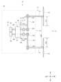
- FIG. 1 is a top view showing the flight device 10.
- the flight device 10 is a device that flies in the air by having a vertical flight rotor 11 and a horizontal flight rotor 12. Specifically, the flight device 10 is a VTOL. The flight device 10 can take off and land in the vertical direction by rotating the vertical flight rotor 11. Furthermore, the flight device 10 can fly forward in the horizontal direction by rotating the horizontal flight rotor 12.
- the flight device 10 is also called a drone, a hybrid drone, or a parallel hybrid drone.
- the flight device 10 mainly comprises a main body 20, a first wing section 21 and a second wing section 22, a rotor 11 for vertical flight, a rotor 12 for horizontal flight, and an engine 40.
- the flight device 10 also comprises transmission equipment such as sensors and a CPU, a fuel tank, cargo to be transported, etc.
- the main body 20 is made of a synthetic resin plate or a metal plate, and is a generally cylindrical member that extends in the front-to-rear direction.
- the engine 40, various electrical equipment, luggage, etc. are stored inside the main body 20.
- the first wing portion 21 and the second wing portion 22 are wing-shaped portions that extend in the left-right direction from the main body portion 20.
- the first wing portion 21 extends leftward from the left side surface of the main body portion 20.
- the second wing portion 22 extends rightward from the right side surface of the main body portion 20.
- the vertical flight rotor 11 is a rotor rotated by a motor 13.
- the vertical flight rotor 11 rotates around a vertical axis when the flight device 10 takes off, lands, or hover. This rotation of the vertical flight rotor 11 allows the flight device 10 to ascend, descend, or hover along the vertical direction.
- the position of the vertical flight rotor 11 may be fixed so that the rotation axis is perpendicular to the horizontal plane that is the main surface of the first wing section 21 and the second wing section 22.
- the vertical flight rotor 11 may be configured so that the rotation axis can be displaced by an actuator or the like.
- the vertical flight rotor 11 has a first sub-rotor 111 to a fourth sub-rotor 114.
- the first sub-rotor 111 and the second sub-rotor 112 are provided on the first wing portion 21.
- the first sub-rotor 111 is disposed inside a first installation hole 241, which is a substantially circular through-hole provided in the first wing portion 21.
- the first sub-rotor 111 is rotated by a first motor 131.
- the second sub-rotor 112 is disposed inside a second installation hole 242, which is a substantially circular through-hole provided in the first wing portion 21.
- the second sub-rotor 112 is rotated by a second motor 132.
- the third sub-rotor 113 and the fourth sub-rotor 114 are provided on the second wing portion 22.
- the third sub-rotor 113 is disposed inside a third installation hole 243, which is a substantially circular through-hole provided in the second wing portion 22.
- the third sub-rotor 113 is rotated by a third motor 133.
- the fourth sub-rotor 114 is disposed inside a fourth installation hole 244, which is a substantially circular through-hole provided in the second wing portion 22.
- the fourth sub-rotor 114 is rotated by a fourth motor 134.
- the horizontal flight rotor 12 is a rotor that rotates by being drivingly connected to the engine 40.
- the horizontal flight rotor 12 rotates around a horizontal axis, which is the longitudinal direction of the main body 20. This rotation of the horizontal flight rotor 12 enables the flight device 10 to fly forward along the horizontal direction.
- the horizontal flight rotor 12 has a first horizontal flight rotor 121 and a second horizontal flight rotor 122.
- the first horizontal flight rotor 121 and the second horizontal flight rotor 122 are arranged side by side in the left-right direction at the rear end of the main body 20.
- the first horizontal flight rotor 121 and the second horizontal flight rotor 122 rotate around a horizontal axis along the front-rear direction, generating a thrust that propels the flight device 10 forward.
- the drive force transmission structure that transmits the drive force of the engine 40 to the first horizontal flight rotor 121 and the second horizontal flight rotor 122 will be described with reference to Figure 2.
- the calculation control unit 29 is, for example, a CPU, and receives the output of each sensor mounted on the flight device 10, and controls the operation of each device such as the vertical flight rotor 11 and the horizontal flight rotor 12.
- the vertical flight rotor 11 is rotated by the motor 13, and the rotation speed of the vertical flight rotor 11 can be controlled with high precision by the motor 13 during takeoff, landing, and hovering, ensuring the stability of the flight device 10 in the air.
- the engine 40 drives the rotation of the horizontal flight rotor 12, allowing the horizontal flight rotor 12 to rotate with high efficiency, thereby lengthening the continuous flight distance of the flight device 10.
- Figure 2 is a top view showing the power transmission structure in the vicinity of the engine 40 and horizontal flight rotor 12 of the flight device 10.
- the horizontal flight rotor 12 is driven by the engine 40.
- a power interrupter 25 is provided between the engine 40 and the horizontal flight rotor 12.
- an engine side drive shaft 18, a power interrupter 25, a power transmission unit 16, and a rotor drive shaft 17 are arranged as means for transmitting power.
- a generator 15 driven by the engine 40 is arranged near the engine 40.
- the engine 40 has a first engine section 41 and a second engine section 42 that are arranged opposite each other to achieve low vibration.
- the first engine section 41 generates a rotational driving force for driving the first horizontal flight rotor 121 and the generator 151.
- the second engine section 42 generates a rotational driving force for driving the second horizontal flight rotor 122 and the generator 152.
- the specific structure of the engine 40 will be described with reference to FIG. 3.
- the engine-side drive shaft 18 is a drive shaft that is connected to and rotates with the crankshaft of the engine 40, which will be described later.
- a first engine-side drive shaft 181 and a second engine-side drive shaft 182 are derived from the engine 40 as the engine-side drive shaft 18.
- the first engine drive shaft 181 is connected to the first crankshaft 412 of the first engine section 41, which will be described later, and is a drive shaft that transmits the rotational driving force that rotates the first horizontal flight rotor 121.
- the first engine drive shaft 181 has a first front drive shaft 1811, which is its forward portion, and a first rear drive shaft 1812, which is its rear portion.
- a first power connection/disconnection unit 251, which will be described later, is disposed between the first front drive shaft 1811 and the first rear drive shaft 1812.
- a second pulley 232 is connected to the rear end of the first rear drive shaft 1812 so as to be non-rotatable relative to the first rear drive shaft 1812.
- the second engine drive shaft 182 is connected to the second crankshaft 422 of the second engine section 42, which will be described later, and is a drive shaft that transmits the rotational driving force that rotates the second horizontal flight rotor 122.
- the second engine drive shaft 182 has a second front drive shaft 1821, which is its forward portion, and a second rear drive shaft 1822, which is its rear portion.
- a second power connection/disconnection unit 252, which will be described later, is disposed between the second front drive shaft 1821 and the second rear drive shaft 1822.
- a third pulley 233 is connected to the rear end of the second rear drive shaft 1822 in a manner that prevents relative rotation.
- the power interrupter 25 is disposed between the engine 40 and the horizontal flight rotor 12, and is a device that interrupts the power transmitted from the engine 40 to the horizontal flight rotor 12.
- a clutch can be used as the power interrupter 25, and more specifically, an electromagnetic clutch or a centrifugal clutch can be used.
- the power interrupter 25 has a first power interrupter 251 and a second power interrupter 252.
- the first power interrupter 251 is disposed between the first front drive shaft 1811 and the first rear drive shaft 1812. When the first power interrupter 251 is in a connected state, the rotational drive force is transmitted from the first front drive shaft 1811 to the first rear drive shaft 1812. On the other hand, when the first power interrupter 251 is in a disconnected state, the rotational drive force is not transmitted from the first front drive shaft 1811 to the first rear drive shaft 1812.
- the second power interrupter 252 is disposed between the second front drive shaft 1821 and the second rear drive shaft 1822.
- the rotational drive force is transmitted from the second front drive shaft 1821 to the second engine-side drive shaft 182.
- the rotational drive force is not transmitted from the second front drive shaft 1821 to the second rear drive shaft 1822.
- the rotor drive shaft 17 has a first rotor drive shaft 171 and a second rotor drive shaft 172.
- the first rotor drive shaft 171 is a generally rod-shaped member that rotates the first horizontal flight rotor 121.
- the first horizontal flight rotor 121 is connected to the rear end of the first rotor drive shaft 171 in a manner that prevents relative rotation.
- the first pulley 231 is connected to the front end of the first rotor drive shaft 171 in a manner that prevents relative rotation.
- the second rotor drive shaft 172 is a generally rod-shaped member that rotates the second horizontal flight rotor 122.
- the second horizontal flight rotor 122 is connected to the rear end of the second rotor drive shaft 172 in a manner that prevents relative rotation.
- the fourth pulley 234 is connected to the front end of the second rotor drive shaft 172 in a manner that prevents relative rotation.
- the power transmission unit 16 has a first power transmission unit 161 and a second power transmission unit 162.
- a belt, a transmission rod, a gear train, etc. can be used as the first power transmission unit 161 and the second power transmission unit 162.
- a belt is used as an example of the first power transmission unit 161 and the second power transmission unit 162.
- the first power transmission unit 161 is configured to extend along a direction intersecting the axial direction of the first rotor drive shaft 171 or the first engine side drive shaft 181. Specifically, the axial direction of the first rotor drive shaft 171 or the first engine side drive shaft 181 extends along the front-rear direction. The first power transmission unit 161 also extends along the left-right direction. Therefore, here, the axial direction of the first rotor drive shaft 171 or the first engine side drive shaft 181 and the first power transmission unit 161 are perpendicular to each other. In this way, the first rotor drive shaft 171 can be disposed on the left side.
- the first power transmission unit 161 which is a belt, is stretched between the first pulley 231 and the second pulley 232. With this configuration, the first power transmission unit 161 drivingly connects the first rotor drive shaft 171 and the first engine side drive shaft 181.
- the second power transmission unit 162 is configured to extend along a direction intersecting the axial direction of the second rotor drive shaft 172 or the second engine side drive shaft 182. Specifically, the axial direction of the second rotor drive shaft 172 or the second engine side drive shaft 182 extends along the front-rear direction. The second power transmission unit 162 also extends along the left-right direction. Therefore, here, the axial direction of the second rotor drive shaft 172 or the second engine side drive shaft 182 and the second power transmission unit 162 are perpendicular to each other. In this way, the second rotor drive shaft 172 can be disposed on the right side.
- the second power transmission unit 162 which is a belt, is stretched between the third pulley 233 and the fourth pulley 234. With this configuration, the second power transmission unit 162 drivingly connects the second rotor drive shaft 172 and the second engine side drive shaft 182.
- first horizontal flight rotor 121 and the second horizontal flight rotor 122 are sufficiently separated, and physical contact between the first horizontal flight rotor 121 and the second horizontal flight rotor 122 during rotation is suppressed, and aerodynamic interference is also suppressed.
- the generator 15 is a device that generates electricity using the driving force of the engine 40.
- the generator 15 has a generator 151 and a generator 152.
- the generator 151 is connected to a first crankshaft 412 of the first engine section 41 (described later) via a generator side drive shaft 261.
- the generator 152 is connected to a second crankshaft 422 of the second engine section 42 (described later) via a generator side drive shaft 262.
- the vertical flight rotor 11 described above rotates using the electricity generated by the generators 151 and 152.
- the first power interrupter 251 and the second power interrupter 252 are in a connected state.
- the rotational driving force generated by the rotation of the first engine section 41 is transmitted in the order of the first front drive shaft 1811, the first power interrupter 251, the first rear drive shaft 1812, the first power transmission section 161, and the first rotor drive shaft 171, thereby rotating the first horizontal flight rotor 121.
- the rotational driving force of the first engine section 41 is also transmitted to the generator 151 via the generator side drive shaft 261, and the generator 151 performs a power generation operation.
- the rotational driving force generated by the rotation of the second engine section 42 is transmitted in the order of the second front drive shaft 1821, the second power connection/disconnection section 252, the second rear drive shaft 1822, the second power transmission section 162, and the second rotor drive shaft 172, causing the second horizontal flight rotor 122 to rotate.
- the rotational driving force of the second engine section 42 is also transmitted to the generator 152 via the generator side drive shaft 262, causing the generator 152 to generate electricity.
- the rotation of the first horizontal flight rotor 121 and the second horizontal flight rotor 122 provides thrust for flying the flight device 10 forward.
- FIG. 3 is a top view showing the vicinity of the engine 40 of the flight device 10.
- the engine 40 is an opposed type engine.
- the engine 40 has a first engine section 41 and a second engine section 42 arranged opposite the first engine section 41.
- the first engine section 41 and the second engine section 42 are housed inside a casing block 43.
- the first engine section 41 has a first piston 411, a first crankshaft 412, and a first connecting rod 413.
- the first connecting rod 413 rotatably connects the first piston 411 and the first crankshaft 412.
- the second engine section 42 has a second piston 421, a second crankshaft 422, and a second connecting rod 423.
- the second connecting rod 423 rotatably connects the second piston 421 and the second crankshaft 422.
- the first crankshaft 412 has its front end connected to the generator side drive shaft 261 and its rear end connected to the first engine side drive shaft 181.
- the second crankshaft 422 has its front end connected to the generator side drive shaft 262 and its rear end connected to the second engine side drive shaft 182.
- a first piston 411 and a second piston 421 are disposed inside the cylinder 44. Inside the cylinder 44, the space sandwiched between the first piston 411 and the second piston 421 forms the combustion chamber 45. The first piston 411 and the second piston 421 reciprocate in opposition to each other inside the cylinder 44. This motion causes the first crankshaft 412 and the second crankshaft 422 to rotate. The rotation direction of the first crankshaft 412 and the rotation direction of the second crankshaft 422 are opposite to each other.
- the engine 40 has a first engine section 41 and a second engine section 42 arranged opposite each other, which greatly reduces vibration during operation. This prevents various sensors mounted on the flight device 10, such as acceleration sensors and orientation sensors, from malfunctioning due to vibrations generated when the engine 40 is operating.
- the flight device 10 configured as shown in Figures 1 to 3 performs vertical takeoff, hovering, horizontal flight, and vertical landing as follows.
- the first motor 131 to the fourth motor 134 rotate the first sub-rotor 111 to the fourth sub-rotor 114 at a predetermined rotation speed.
- the flight device 10 floats from a landing surface such as the ground and rises until it reaches a predetermined altitude.
- the calculation control unit 29 individually controls the rotation speeds of the first motor 131 to the fourth motor 134 based on the output of each sensor so that the position and attitude of the flight device 10 in the air is predetermined.
- the calculation control unit 29 disconnects the power disconnect unit 25, so that the driving force of the engine 40 is not transmitted to the horizontal flight rotor 12, and the horizontal flight rotor 12 does not rotate.
- the flying device 10 can take off at high speed by increasing the amount of power generated by the generator 15, driving the first motor 131 to the fourth motor 134 at high speed, and rotating the first sub-rotor 111 to the fourth sub-rotor 114 at high speed.
- the power generated by the engine 40 is supplied directly to the first motor 131 to the fourth motor 134 without going through the battery. The same applies during hovering and landing.
- the first motor 131 to the fourth motor 134 are rotated at a predetermined speed based on the instructions of the calculation control unit 29.
- the calculation control unit 29 also adjusts the rotation speeds of the first motor 131 to the fourth motor 134 individually so that the position and attitude of the flight device 10 in the air is predetermined. In this way, the flight device 10 can perform hovering in the air with a constant altitude and position and attitude. Even in hovering, the calculation control unit 29 disconnects the first power interrupter 251 and the second power interrupter 252, and does not rotate the first horizontal flight rotor 121 and the second horizontal flight rotor 122. Therefore, the generators 151 and 152 can generate electricity using all of the power generated by the operation of the first engine unit 41 and the first engine unit 41.
- the calculation control unit 29 connects the first power connection/disconnection unit 251 and the second power connection/disconnection unit 252.
- the rotational driving force of the first engine unit 41 of the engine 40 is transmitted to the first horizontal flight rotor 121 via the first engine side drive shaft 181, the first power transmission unit 161, and the first rotor drive shaft 171.
- the first horizontal flight rotor 121 rotates at a predetermined rotational speed.
- the rotational driving force of the second engine unit 42 of the engine 40 is transmitted to the second horizontal flight rotor 122 via the second engine side drive shaft 182, the second power transmission unit 162, and the second rotor drive shaft 172.
- the second horizontal flight rotor 122 rotates at a predetermined rotational speed.
- the flight device 10 starts to move forward along the horizontal run.
- the calculation control unit 29 continues to rotate the first motor 131 to the fourth motor 134, and the first sub-rotor 111 to the fourth sub-rotor 114 continue to rotate. In this way, the calculation control unit 29 starts the horizontal direction while floating stably due to the rotation of the first sub-rotor 111 to the fourth sub-rotor 114.
- the calculation control unit 29 does not rotate the first motor 131 to the fourth motor 134, so that the first sub-rotor 111 to the fourth sub-rotor 114 are stopped.
- the calculation and control unit 29 When transitioning from horizontal flight to vertical landing, the calculation and control unit 29 reduces the output of the engine 40 to slow the rotational speed of the first horizontal flight rotor 121 and the second horizontal flight rotor 122. This slows down the movement speed of the flight device 10. At the same time, the calculation and control unit 29 drives the first motor 131 to the fourth motor 134 to rotate, thereby rotating the first sub-rotor 111 and the fourth sub-rotor 114 to obtain a predetermined buoyancy.
- the calculation and control unit 29 rotates the first sub-rotor 111 to the fourth sub-rotor 114 at a predetermined rotation speed by adjusting the rotation speed of the first motor 131 and the fourth motor 134. This causes the flight device 10 to gradually lower its altitude until it lands on the ground. At this time, the calculation and control unit 29 disconnects the first power interrupter 251 and the second power interrupter 252, so that the first horizontal flight rotor 121 and the second horizontal flight rotor 122 do not rotate. In this way, more of the rotational power of the engine 40 can be distributed to the generators 151 and 152, increasing the amount of power generation. Therefore, the first motor 131 to the fourth motor 134 can be rotated stably by the large power generated by the generators 151 and 152.
- the configuration of a flight device 10 according to another embodiment will be described with reference to Figures 4 to 6.
- the basic configuration and basic operation of the flight device 10 shown in Figures 4 to 6 are the same as that shown in Figure 1.
- the first horizontal flight rotor 121 and the second horizontal flight rotor 122 are stacked on the rear end side of the main body 20. The following description will focus on these points.
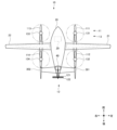
- FIG. 4 is a top view of a flying device 10 according to another embodiment.
- FIG. 5 is a side view of a flying device 10 according to another embodiment.
- the flight device 10 has a first horizontal flight rotor 121 and a second horizontal flight rotor 122 that are stacked as the horizontal flight rotor 12.
- the horizontal flight rotor 12 having such a configuration is also called a pusher.
- the first horizontal flight rotor 121 and the second horizontal flight rotor 122 are driven to rotate by the engine 40.
- the flying device 10 has a main body 20, a first wing 21, and a second wing 22.
- an outrigger 301 is disposed under the first wing 21, and an outrigger 302 is disposed under the second wing 22.
- the flying device 10 has the first sub-rotor 111 to the fourth sub-rotor 114 and the first motor 131 to the fourth motor 134, similar to that shown in FIG. 1.
- the first sub-rotor 111 and the first motor 131 are arranged in the forward portion of the outrigger 301.
- the second sub-rotor 112 and the second motor 132 are arranged in the rear portion of the outrigger 301.
- the third sub-rotor 113 and the third motor 133 are arranged in the forward portion of the outrigger 302.
- the fourth sub-rotor 114 and the fourth motor 134 are arranged in the rear portion of the outrigger 302.
- a bladder tank for storing fuel is disposed inside the first wing section 21 and the second wing section 22. Furthermore, disposed inside the main body section 20 are various devices constituting the control system, such as the calculation control section 29, the cargo transported by the flight device 10, and batteries that supply power to the various electrical devices constituting the flight device 10.
- legs 28 are installed on the bottom of the main body 20.
- the legs 28 are the parts that come into contact with the ground when the flying device 10 lands.
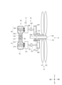
- FIG. 6 is a top view showing the vicinity of the engine 40 and horizontal flight rotor 12 of a flight device 10 according to another embodiment.
- the basic configuration and basic operation of the engine 40 and horizontal flight rotor 12 shown in FIG. 6 are the same as those described with reference to FIG. 2.
- the drive shaft 19 is shown which drivingly connects the engine 40 and the horizontal flight rotor 12.
- the drive shaft 19 has a first drive shaft 191 which drivingly connects the engine 40 and the first horizontal flight rotor 121, and a second drive shaft 192 which drivingly connects the engine 40 and the second horizontal flight rotor 122. This configuration will be described in detail below.
- the generator 151 is disposed to the rear of the first engine section 41, and is driven to rotate by the first engine side drive shaft 181.
- the generator 151 has a rotor (not shown), and this rotor is connected to the first engine side drive shaft 181 so as not to be rotatable. With this configuration, the rotor built into the generator 151 rotates together with the first engine side drive shaft 181, thereby generating electricity by the generator 151.
- the configuration of the generator 152 is the same as that of the generator 151. Specifically, the generator 152 is disposed on the rear side of the second engine section 42, and is rotationally driven by the second engine side drive shaft 182. The generator 152 has a rotor (not shown), and this rotor is connected to the second engine side drive shaft 182 so as not to rotate. With this configuration, the rotor built into the generator 152 rotates together with the second engine side drive shaft 182, thereby generating electricity by the generator 152.
- the drive shaft 19 is a generally shaft-shaped member that rotates due to the driving force generated by the engine 40, thereby rotating the horizontal flight rotor 12 described above.
- the drive shaft 19 has a first drive shaft 191 that is rotated by the first engine section 41, and a second drive shaft 192 that is rotated by the second engine section 42.
- the drive shaft 19 has a mechanism that mechanically rotates coaxially in the opposite direction.
- the first drive shaft 191 has its rear end connected to the first horizontal flight rotor 121, thereby rotating the first horizontal flight rotor 121.
- the vicinity of the front end of the first drive shaft 191 is drivingly connected to the first engine side drive shaft 181 via the first belt 271. That is, the rotational driving force generated by the first engine section 41 is transmitted to the first drive shaft 191 via the first engine side drive shaft 181 and the first belt 271.
- the second drive shaft 192 has its rear end connected to the second horizontal flight rotor 122, thereby rotating the second horizontal flight rotor 122.
- the vicinity of the front end of the second drive shaft 192 is drivingly connected to the second engine side drive shaft 182 via the second belt 272. That is, the rotational driving force generated by the second engine section 42 is transmitted to the second drive shaft 192 via the second engine side drive shaft 182 and the second belt 272.
- the first belt 271 transmits the rotational driving force of the first engine side drive shaft 181 to the first drive shaft 191.
- the first belt 271 is stretched between the eighth pulley 238 and the seventh pulley 237.
- the eighth pulley 238 is connected to the rear end of the first engine side drive shaft 181 so as not to rotate relative to it.
- the seventh pulley 237 is connected to the front end of the first drive shaft 191 so as not to rotate relative to it.
- the first belt 271 is stretched between the eighth pulley 238 and the seventh pulley 237.
- the power interrupter 25 can be installed on the engine side drive shaft 18.
- the power interrupter 25 has a first power interrupter 251 and a second power interrupter 252.
- the first power connection/disconnection unit 251 is located in the middle of the first engine side drive shaft 181 and is interposed between the generator 151 and the eighth pulley 238.
- the first power connection/disconnection unit 251 When the first power connection/disconnection unit 251 is in a connected state, the first drive shaft 191 and the first horizontal flight rotor 121 can be rotated via the first engine side drive shaft 181 by the rotational power generated by the operation of the first engine unit 41. At the same time, power is generated by the generator 151.
- the second power connection/disconnection unit 252 is located in the middle of the second engine side drive shaft 182 and is interposed between the generator 152 and the fifth pulley 235.
- the second power connection/disconnection unit 252 When the second power connection/disconnection unit 252 is in a connected state, the second drive shaft 192 and the second horizontal flight rotor 122 can be rotated via the second engine side drive shaft 182 by the rotational power generated by the operation of the second engine unit 42. At the same time, power is generated by the generator 152.
- the operation of the flight device 10 shown in Figures 4 to 6 is similar to that of the flight device 10 shown in Figures 1 to 3. Specifically, the flight device 10 configured as shown in Figures 4 to 6 performs vertical takeoff, hovering, horizontal flight, and vertical landing as follows.
- the first motor 131 to the fourth motor 134 rotate the first sub-rotor 111 to the fourth sub-rotor 114 at a predetermined rotation speed.
- the flight device 10 floats from a landing surface such as the ground and rises until it reaches a predetermined altitude.
- the calculation control unit 29 individually controls the rotation speeds of the first motor 131 to the fourth motor 134 based on the output of each sensor so that the position and attitude of the flight device 10 in the air is predetermined.
- the calculation control unit 29 disconnects the first power disconnection unit 251 and the second power disconnection unit 252 shown in FIG.
- the driving force of the first engine unit 41 and the second engine unit 42 is not transmitted to the first horizontal flight rotor 121 and the second horizontal flight rotor 122, and therefore the first horizontal flight rotor 121 and the second horizontal flight rotor 122 do not rotate.
- all or most of the driving force of the first engine section 41 and the second engine section 42 can be supplied to the generators 151 and 152. Therefore, the amount of electric power generated by the generators 151 and 152 can be increased, the first motor 131 to the fourth motor 134 can be driven at high speed, and the first sub-rotor 111 to the fourth sub-rotor 114 can be rotated at high speed, allowing the flight device 10 to take off at high speed.
- the electric power generated by the engine 40 can be supplied directly to the first motor 131 to the fourth motor 134 without going through a battery. The same applies during hovering and landing.
- the first motor 131 to the fourth motor 134 are rotated at a predetermined speed based on the instructions of the calculation control unit 29.
- the calculation control unit 29 also adjusts the rotation speeds of the first motor 131 to the fourth motor 134 individually so that the position and attitude of the flight device 10 in the air is predetermined. In this way, the flight device 10 can perform hovering in the air with a constant altitude and position and attitude. Even in hovering, the calculation control unit 29 disconnects the first power interrupter 251 and the second power interrupter 252, and does not rotate the first horizontal flight rotor 121 and the second horizontal flight rotor 122. Therefore, the generators 151 and 152 can generate electricity using all of the power generated by the operation of the first engine unit 41 and the first engine unit 41.
- the calculation control unit 29 connects the first power connection/disconnection unit 251 and the second power connection/disconnection unit 252.
- the rotational driving force of the first engine unit 41 of the engine 40 is transmitted to the first horizontal flight rotor 121 via the first engine side drive shaft 181, the first power connection/disconnection unit 251, and the first belt 271.
- the first horizontal flight rotor 121 rotates at a predetermined rotational speed.
- the rotational driving force of the second engine unit 42 of the engine 40 is transmitted to the second horizontal flight rotor 122 via the second engine side drive shaft 182, the second power connection/disconnection unit 252, and the second belt 272.
- the second horizontal flight rotor 122 rotates at a predetermined rotational speed.
- the flight device 10 starts to move horizontally, i.e., forward.
- the calculation control unit 29 continues to rotate the first motor 131 to the fourth motor 134, and the first sub-rotor 111 to the fourth sub-rotor 114 continue to rotate. In this way, the calculation control unit 29 starts the horizontal direction while floating stably due to the rotation of the first sub-rotor 111 to the fourth sub-rotor 114.
- the first horizontal flight rotor 121 and the second horizontal flight rotor 122 rotate at high speed, allowing the flight device 10 to fly at high speed in the horizontal direction, i.e., in the forward direction.
- the calculation control unit 29 does not rotate the first motor 131 to the fourth motor 134, so that the first sub-rotor 111 to the fourth sub-rotor 114 are stopped.
- the calculation and control unit 29 When transitioning from horizontal flight to vertical landing, the calculation and control unit 29 reduces the output of the engine 40 to slow the rotational speed of the first horizontal flight rotor 121 and the second horizontal flight rotor 122. This slows down the movement speed of the flight device 10. At the same time, the calculation and control unit 29 drives the first motor 131 to the fourth motor 134 to rotate, thereby rotating the first sub-rotor 111 and the fourth sub-rotor 114 to obtain a predetermined buoyancy.
- the calculation and control unit 29 rotates the first sub-rotor 111 to the fourth sub-rotor 114 at a predetermined rotation speed by adjusting the rotation speed of the first motor 131 and the fourth motor 134. This causes the flight device 10 to gradually lower its altitude until it lands on the ground. At this time, the calculation and control unit 29 disconnects the first power interrupter 251 and the second power interrupter 252, so that the first horizontal flight rotor 121 and the second horizontal flight rotor 122 do not rotate. In this way, more of the rotational power of the engine 40 can be distributed to the generators 151 and 152, increasing the amount of power generation. Therefore, the first motor 131 to the fourth motor 134 can be rotated stably by the large power generated by the generators 151 and 152.
- the first horizontal flight rotor 121 is rotated by the first engine section 41, and the second horizontal flight rotor 122 is rotated by the second engine section 42, so that the first horizontal flight rotor 121 and the second horizontal flight rotor 122 can be rotated individually and with high efficiency.
- the power transmission to the horizontal flight rotor 12 is interrupted by the power interrupter 25, so that the power of the engine 40 can be used for generating electricity, etc.
- the power is transmitted by the power interrupter 25, so that the horizontal flight rotor 12 can be rotated by the engine 40 with high efficiency.
- the first power transmission unit 161 and the second power transmission unit 162 extend in a direction perpendicular to each rotor drive shaft 17 and each engine side drive shaft 18, so that the first rotor drive shaft 171 and the second rotor drive shaft 172 can be separated from each other. This makes it possible to prevent interference between the first horizontal flight rotor 121 and the second horizontal flight rotor 122 during rotation.
- the first drive shaft 191 and the second drive shaft 192 are arranged coaxially, so that the second horizontal flight rotor 122 and the second horizontal flight rotor 122, which are arranged in a superimposed manner, can be effectively rotated.
- the flight device of the present invention has a vertical flight rotor and a horizontal flight rotor, the vertical flight rotor being rotated by a motor, and the horizontal flight rotor being driven and connected to an engine, thereby rotating.
- the vertical flight rotor is rotated by the motor, so that the rotation speed of the vertical flight rotor can be controlled with high precision by the motor during takeoff and landing.
- the engine drives the rotation of the horizontal flight rotor, so that the horizontal flight rotor can be rotated with high efficiency, and the continuous flight distance of the flight device can be increased.
- the flight device of the present invention is also characterized in that a power interrupter is provided between the engine and the horizontal flight rotor.
- a power interrupter is provided between the engine and the horizontal flight rotor.
- the flying device of the present invention is also characterized by being further equipped with a generator driven by the engine.
- a generator driven by the engine.
- the flight device of the present invention further includes a power transmission unit and a rotor drive shaft
- the horizontal flight rotor has a first horizontal flight rotor and a second horizontal flight rotor
- the power transmission unit has a first power transmission unit and a second power transmission unit
- the rotor drive shaft has a first rotor drive shaft and a second rotor drive shaft
- the first horizontal flight rotor is rotated via the first rotor drive shaft
- the second horizontal flight rotor is rotated via the second rotor drive shaft
- a first engine side drive shaft is provided from the engine.
- the first power transmission unit is configured to extend along a direction intersecting with the axial direction of the first rotor drive shaft or the first engine side drive shaft, and drives the first rotor drive shaft and the first engine side drive shaft
- the second power transmission unit is configured to extend along a direction intersecting with the axial direction of the second rotor drive shaft or the second engine side drive shaft, and drives the second rotor drive shaft and the second engine side drive shaft.
- the first power transmission unit and the second power transmission unit extend, for example, along a direction perpendicular to each rotor drive shaft and each engine side drive shaft, so that the first rotor drive shaft and the second rotor drive shaft can be separated. Therefore, interference between the first horizontal flight rotor and the second horizontal flight rotor during rotation can be suppressed.
- the engine has a first engine section and a second engine section arranged to face the first engine section
- the horizontal flight rotor has a first horizontal flight rotor and a second horizontal flight rotor
- the first horizontal flight rotor is rotated by the first engine section
- the second horizontal flight rotor is rotated by the second engine section.
- the flight device of the present invention further comprises a drive shaft that drivingly connects the engine and the horizontal flight rotor, the horizontal flight rotor having a first horizontal flight rotor and a second horizontal flight rotor arranged so as to overlap the first horizontal flight rotor, and the drive shaft has a first drive shaft that drivingly connects the engine and the first horizontal flight rotor, and a second drive shaft that drivingly connects the engine and the second horizontal flight rotor.
- the flight device of the present invention by having the first horizontal flight rotor and the second horizontal flight rotor arranged so as to overlap, horizontal flight can be effectively performed.
- the flight device of the present invention is characterized in that the first drive shaft and the second drive shaft are arranged coaxially. According to the flight device of the present invention, by arranging the first drive shaft and the second drive shaft coaxially, the first horizontal flight rotor and the second horizontal flight rotor, which are arranged in a superimposed manner, can be effectively rotated.
- Flight device 11 Vertical flight rotor 111 First sub rotor 112 Second sub rotor 113 Third sub rotor 114 Fourth sub rotor 12 Horizontal flight rotor 121 First horizontal flight rotor 122 Second horizontal flight rotor 13 Motor 131 First motor 132 Second motor 133 Third motor 134 Fourth motor 15 Generator 151 Generator 152 Generator 16 Power transmission section 161 First power transmission section 162 Second power transmission section 17 Rotor drive shaft 171 First rotor drive shaft 172 Second rotor drive shaft 18 Engine side drive shaft 181 First engine side drive shaft 1811 First front drive shaft 1812 First rear drive shaft 182 Second engine side drive shaft 1821 Second front drive shaft 1822 Second rear drive shaft 19 Drive shaft 191 First drive shaft 192 Second drive shaft 20 Main body 21 First wing portion 22 Second wing portion 231 First pulley 232 Second pulley 233 Third pulley 234 Fourth pulley 235 Fifth pulley 236 Sixth pulley 237 Seventh pulley 238 Eighth pulley 241 First installation hole 242 Second installation hole 243
Landscapes
- Engineering & Computer Science (AREA)
- Aviation & Aerospace Engineering (AREA)
- Mechanical Engineering (AREA)
- Chemical & Material Sciences (AREA)
- Combustion & Propulsion (AREA)
- Remote Sensing (AREA)
- Transportation (AREA)
- Transmission Devices (AREA)
- Arrangement Of Transmissions (AREA)
Priority Applications (1)
| Application Number | Priority Date | Filing Date | Title |
|---|---|---|---|
| CN202480027708.8A CN121013812A (zh) | 2023-12-19 | 2024-11-07 | 飞行装置 |
Applications Claiming Priority (2)
| Application Number | Priority Date | Filing Date | Title |
|---|---|---|---|
| JP2023213823A JP7438589B1 (ja) | 2023-12-19 | 2023-12-19 | 飛行装置 |
| JP2023-213823 | 2023-12-19 |
Publications (1)
| Publication Number | Publication Date |
|---|---|
| WO2025134572A1 true WO2025134572A1 (ja) | 2025-06-26 |
Family
ID=90011450
Family Applications (1)
| Application Number | Title | Priority Date | Filing Date |
|---|---|---|---|
| PCT/JP2024/039612 Pending WO2025134572A1 (ja) | 2023-12-19 | 2024-11-07 | 飛行装置 |
Country Status (3)
| Country | Link |
|---|---|
| JP (2) | JP7438589B1 (enExample) |
| CN (1) | CN121013812A (enExample) |
| WO (1) | WO2025134572A1 (enExample) |
Citations (7)
| Publication number | Priority date | Publication date | Assignee | Title |
|---|---|---|---|---|
| JP2009202737A (ja) * | 2008-02-27 | 2009-09-10 | Mitsubishi Heavy Ind Ltd | 無人航空機及び無人航空機システム |
| JP2011521833A (ja) * | 2008-05-30 | 2011-07-28 | ジロ インダストリーズ リミテッド | 対の二重反転垂直軸プロペラを備えるフライングマシン |
| WO2015157114A1 (en) * | 2014-04-11 | 2015-10-15 | Sada-Salinas Jaime G | Modular nacelles to provide vertical takeoff and landing (vtol) capabilities to fixed wing aerial vehicles, and associated systems and methods |
| US20180029703A1 (en) * | 2015-02-16 | 2018-02-01 | Hutchinson | Vtol aerodyne with supporting axial blower(s) |
| WO2018078388A1 (en) * | 2016-10-27 | 2018-05-03 | Mono Aerospace Ip Ltd | Vertical take-off and landing aircraft and control method |
| JP2020069975A (ja) * | 2018-11-02 | 2020-05-07 | 本田技研工業株式会社 | ハイブリッド飛行体 |
| JP2021020674A (ja) * | 2020-01-17 | 2021-02-18 | 株式会社Ie | エンジン搭載自立型飛行装置 |
Family Cites Families (1)
| Publication number | Priority date | Publication date | Assignee | Title |
|---|---|---|---|---|
| JP6879866B2 (ja) * | 2017-08-28 | 2021-06-02 | 本田技研工業株式会社 | 垂直離着陸機 |
-
2023
- 2023-12-19 JP JP2023213823A patent/JP7438589B1/ja active Active
-
2024
- 2024-01-19 JP JP2024006722A patent/JP2025097874A/ja active Pending
- 2024-11-07 WO PCT/JP2024/039612 patent/WO2025134572A1/ja active Pending
- 2024-11-07 CN CN202480027708.8A patent/CN121013812A/zh active Pending
Patent Citations (7)
| Publication number | Priority date | Publication date | Assignee | Title |
|---|---|---|---|---|
| JP2009202737A (ja) * | 2008-02-27 | 2009-09-10 | Mitsubishi Heavy Ind Ltd | 無人航空機及び無人航空機システム |
| JP2011521833A (ja) * | 2008-05-30 | 2011-07-28 | ジロ インダストリーズ リミテッド | 対の二重反転垂直軸プロペラを備えるフライングマシン |
| WO2015157114A1 (en) * | 2014-04-11 | 2015-10-15 | Sada-Salinas Jaime G | Modular nacelles to provide vertical takeoff and landing (vtol) capabilities to fixed wing aerial vehicles, and associated systems and methods |
| US20180029703A1 (en) * | 2015-02-16 | 2018-02-01 | Hutchinson | Vtol aerodyne with supporting axial blower(s) |
| WO2018078388A1 (en) * | 2016-10-27 | 2018-05-03 | Mono Aerospace Ip Ltd | Vertical take-off and landing aircraft and control method |
| JP2020069975A (ja) * | 2018-11-02 | 2020-05-07 | 本田技研工業株式会社 | ハイブリッド飛行体 |
| JP2021020674A (ja) * | 2020-01-17 | 2021-02-18 | 株式会社Ie | エンジン搭載自立型飛行装置 |
Also Published As
| Publication number | Publication date |
|---|---|
| JP7438589B1 (ja) | 2024-02-27 |
| JP2025097576A (ja) | 2025-07-01 |
| JP2025097874A (ja) | 2025-07-01 |
| CN121013812A (zh) | 2025-11-25 |
Similar Documents
| Publication | Publication Date | Title |
|---|---|---|
| EP3656668B1 (en) | Tilting duct compound helicopter | |
| US11851178B2 (en) | Long range endurance aero platform system | |
| CN111491859B (zh) | 具有反扭矩系统的直升机 | |
| US9004395B2 (en) | Drive system for helicopters | |
| JP7399521B2 (ja) | 飛行装置 | |
| WO2023079900A1 (ja) | 飛行装置 | |
| JP7037826B2 (ja) | プロペラ式飛行体 | |
| CN116834958A (zh) | 搭载发动机的自主型飞行装置及飞行装置 | |
| JP7535308B2 (ja) | 飛行装置 | |
| US8851415B1 (en) | Magnetic aerodynamic generation lift integrated flight technology with joint electric thrust | |
| JP6979251B1 (ja) | 飛行装置 | |
| CN113492989A (zh) | 具有混合推进的飞行器 | |
| KR101654505B1 (ko) | 추력 조절부가 구비된 가변피치형 무인 비행체 | |
| JP7229874B2 (ja) | マルチコプタ | |
| EP4509403A1 (en) | Flying device | |
| WO2017126584A1 (ja) | 無人航空機 | |
| KR20190059588A (ko) | 고효율 장거리용 드론 | |
| CN113928068A (zh) | 一种水下空中跨域航行器及其跨域航行方法 | |
| JP6570095B2 (ja) | 乗り物推進のための発電および分配 | |
| WO2025134572A1 (ja) | 飛行装置 | |
| JP2015000602A (ja) | 垂直離着陸機 | |
| CN113401350A (zh) | 涵道飞行器 | |
| JP7697745B1 (ja) | 飛行装置 | |
| JP7535356B1 (ja) | 飛行装置 | |
| WO2025173191A1 (ja) | 飛行装置 |
Legal Events
| Date | Code | Title | Description |
|---|---|---|---|
| 121 | Ep: the epo has been informed by wipo that ep was designated in this application |
Ref document number: 24906960 Country of ref document: EP Kind code of ref document: A1 |
|
| WWE | Wipo information: entry into national phase |
Ref document number: CN2024800277088 Country of ref document: CN |