WO2025126701A1 - 搬送装置 - Google Patents
搬送装置 Download PDFInfo
- Publication number
- WO2025126701A1 WO2025126701A1 PCT/JP2024/038593 JP2024038593W WO2025126701A1 WO 2025126701 A1 WO2025126701 A1 WO 2025126701A1 JP 2024038593 W JP2024038593 W JP 2024038593W WO 2025126701 A1 WO2025126701 A1 WO 2025126701A1
- Authority
- WO
- WIPO (PCT)
- Prior art keywords
- control
- carriage
- parameter
- vibration
- height
- Prior art date
- Legal status (The legal status is an assumption and is not a legal conclusion. Google has not performed a legal analysis and makes no representation as to the accuracy of the status listed.)
- Pending
Links
Images



Classifications
-
- B—PERFORMING OPERATIONS; TRANSPORTING
- B65—CONVEYING; PACKING; STORING; HANDLING THIN OR FILAMENTARY MATERIAL
- B65G—TRANSPORT OR STORAGE DEVICES, e.g. CONVEYORS FOR LOADING OR TIPPING, SHOP CONVEYOR SYSTEMS OR PNEUMATIC TUBE CONVEYORS
- B65G1/00—Storing articles, individually or in orderly arrangement, in warehouses or magazines
- B65G1/02—Storage devices
- B65G1/04—Storage devices mechanical
Definitions
- the values of the travel control parameters used to control the travel of the trolley are calculated based on the vibration characteristics according to the height of the lift platform. This allows travel control to be performed taking into account the vibration characteristics that change according to the height of the lift platform, making it possible to reduce the vibration of the trolley.
- the control device may include a vibration-damping filter parameter calculation unit that calculates vibration-damping filter parameters based on platform height information, and a vibration-damping filter that filters the position command of the cart using the vibration-damping filter parameters.
- a vibration-damping filter parameter calculation unit that calculates vibration-damping filter parameters based on platform height information
- a vibration-damping filter that filters the position command of the cart using the vibration-damping filter parameters.
- the crane body 1 includes a traveling cart 11, an upper frame 12, two wheels 13, a pair of masts 14, and a carriage 15.
- the traveling cart 11 corresponds to an example of a "cart" in this disclosure.
- the upper frame 12 is disposed on the upper part of the crane body 1 so as to extend in the X direction.
- the upper frame 12 connects the pair of masts 14 to each other.
- the lifting belt Lb is a toothed belt whose both ends are fixed to the carriage 15.
- the lifting belt Lb is wound around a drive pulley 52, and the drive pulley 52 rotates due to the driving force (output torque) of the lifting motor 50, thereby lifting and lowering the carriage 15 in the lifting direction (Z direction).
- the lifting belt Lb may be a V-belt or flat belt, or it may be a chain.
- the upper controller 2 also generates a lifting position command Z* that commands the target position (position in the Z direction: height) of the carriage 15 according to, for example, the operator's operation.
- the upper controller 2 outputs the position command X* and the lifting position command Z* to the controller 7.
- the controller 7 includes a processor 71 and a memory 72.
- the processor 71 includes processing circuits such as a CPU (Central Processing Unit) and an MPU (Micro Processing Unit).
- the memory 72 includes volatile storage devices such as a DRAM (Dynamic Random Access Memory) and an SRAM (Static Random Access Memory), and non-volatile storage devices such as a HDD (Hard Disk Drive), an SSD (Solid State Drive), and a flash memory.
- the memory 72 stores a system program including an OS (Operating System), a control program including computer-readable code, and various parameters for controlling the components of the automated warehouse system 100.
- OS Operating System
- control program including computer-readable code
- the controller 7 may be divided into multiple units based on function. For example, a unit for controlling the travel motor 40 and a unit for controlling the lift motor 50 may be provided separately.
- the controller 7 corresponds to an example of a "control device" in this disclosure.
- the subtraction unit 797 subtracts the position Zr calculated by the position calculation unit 791 from the lift position command Z* input from the upper controller 2.
- the subtraction unit 797 outputs the subtraction value (Z*-Zr) to the position control unit 792.
- the position control unit 792 generates a speed command Vz* so that the subtraction value (Z*-Zr) by the subtraction unit 797 is eliminated (approaching zero).
- the position control unit 792 outputs the generated speed command Vz* to the subtraction unit 798.
- the speed calculation unit 79 calculates the speed Vz at which the carriage 15 moves up and down (the rotational speed of the lift motor 50) based on the signal from the second encoder 32.
- the speed calculation unit 793 outputs the calculated speed Vz to the subtraction unit 798.
- the speed control unit 794 generates a torque command TrS* so that the subtraction value (Vz*-Vz) by the subtraction unit 798 is eliminated (approaching zero).
- the speed control unit 794 outputs the torque command TrS* to the lift motor 50.
- the lift motor 50 is controlled so that the torque of the torque command TrS* is output.
- lift control is performed so that the height H of the carriage 15 matches the target position (the height corresponding to the lift position command Z*).
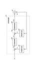
- FIG. 6 is a diagram showing an example of a driving control unit 702, which is a functional block configured in the controller 7.
- the driving control unit 702 controls the driving motor 40.
- the driving control unit 702 includes a feedforward control unit (FF control unit) 710, a feedforward parameter calculation unit (FF parameter calculation unit) 720, a vibration suppression filter 730, a vibration suppression filter parameter calculation unit (vibration suppression F parameter calculation unit) 740, and a feedback control unit (FB control unit) 750.
- FF control unit feedforward control unit
- FF parameter calculation unit a feedforward parameter calculation unit
- FB control unit feedback control unit
- the FF control unit 710 calculates the torque feedforward value (feedforward torque) TrFF using a transfer function G1 obtained from a physical model (for example, a two-inertia model) of the crane body 1.
- the parameters of the transfer function G1 include, for example, the mass of the crane body 1 (traveling cart 11, mast 14, carriage 15), the resonance frequency (primary, secondary), the anti-resonance frequency (primary, secondary), etc.
- the parameters of the transfer function G1 are also referred to as feedforward parameters (FF parameters). Since the center of gravity G of the crane body 1 changes according to the height H of the carriage 15, the vibration characteristics of the crane body 1 change according to the height H.
- the resonance frequency and anti-resonance frequency which are FF parameters, change according to the height H of the carriage 15.
- the FF parameter calculation unit 720 obtains the value of the FF parameter using the height H of the carriage 15 (the position of the carriage 15 in the Z direction), and calculates the torque feedforward value TrFF.
- the height H is determined based on the position Zr of the lifting motor 50 calculated by the position calculation unit 791 (see FIG. 5) from the detection signal of the second encoder 32, and is input to the FF parameter calculation unit 720.
- the height H is the current height of the carriage 15, and corresponds to an example of the "height information" of the present disclosure.
- the FF parameter calculation unit 720 calculates the value of the FF parameter according to the height H and outputs it to the FF control unit 710.
- the memory 72 stores an FF parameter map that is set in advance by simulation, experiment, etc., and the FF parameter calculation unit 720 calculates the value of the FF parameter from the FF parameter map according to the height H.
- the FF parameter map is set based on the vibration characteristics that take into account the center of gravity of the crane body 1, which change according to the height H, for each parameter (for example, resonance frequency (primary, secondary), anti-resonance frequency (primary, secondary)).
- the FF parameter map may be, for example, a two-dimensional map of the FF parameter and the height H.
- the FF parameter calculation unit 720 calculates the value of each FF parameter based on the height H and outputs it to the FF control unit 710.
- the FF parameters correspond to an example of the "travel control parameters" of this disclosure.
- the FF control unit 710 calculates the torque feedforward value TrFF using the transfer function G1 from the position command X* input from the upper controller 2 and the FF parameters calculated by the FF parameter calculation unit 720, and outputs it to the addition unit 719.
- the vibration suppression filter 730 filters the position command X* using the transfer function G2.
- the vibration suppression filter 730 has the function of a notch filter that removes vibration components (frequency components that tend to vibrate the crane body 1) of the position command X*.
- the transfer function G2 like the transfer function G1, is calculated from a physical model of the crane body 1, and its parameters include, for example, the mass of the crane body 1 (traveling cart 11, mast 14, carriage 15), the resonance frequency (primary, secondary), the anti-resonance frequency (primary, secondary), etc.
- the parameters of the transfer function G2 are also referred to as vibration suppression filter parameters (vibration suppression F parameters).
- the resonance frequency and anti-resonance frequency, which are vibration suppression F parameters, change depending on the height H. For this reason, the vibration suppression F parameter calculation unit 740 calculates the value of the vibration suppression F parameter based on the height H, and the vibration suppression filter 730 filters the position command X*.
- the vibration control F parameter map may be, for example, a two-dimensional map of the vibration control F parameter and the height H.
- the vibration control F parameter calculation unit 740 calculates the value of each vibration control F parameter based on the height H.
- the vibration control F parameter corresponds to an example of a "travel control parameter" in this disclosure.
- the vibration suppression filter 730 filters the position command X* using the transfer function G2 and the vibration suppression F parameter calculated by the vibration suppression F parameter calculation unit 740, and outputs the filtered position command Xf to the velocity feedforward unit (velocity FF unit) 712 and the subtraction unit 714.
- the subtraction unit 714 subtracts the position X calculated by the position calculation unit 751 from the position command Xf filtered by the vibration suppression filter 730.
- the subtraction unit 714 outputs the subtraction value (Xf-X) to the position control unit 752.
- the position control unit 752 generates a speed command Vx* so that the subtraction value (Xf-X) by the subtraction unit 714 is eliminated (approaching zero).
- the position control unit 752 outputs the generated speed command Vx* to the calculation unit 717.
- the speed calculation unit 753 calculates the speed Vx at which the crane body 1 moves (the rotational speed of the traveling motor 40) based on the signal from the first encoder 31.
- the speed calculation unit 753 outputs the calculated speed Vx to the calculation unit 717.
- the speed control unit 754 generates a torque command TrR* so that the value (Vx* + VFF - Vx) calculated by the calculation unit 717 is eliminated (approaching zero).
- the speed control unit 754 outputs the generated torque command TrR* to the addition unit 719.
- the adder 719 adds the torque feedforward value TrFF from the FF control unit 710 to the torque command TrR* from the speed control unit 754.
- the adder 719 outputs the added value (TrR* + TrFF) to the traveling motor 40.
- the traveling motor 40 is controlled so that a torque of the added value (TrR* + TrFF) is output.
- the controller 7 uses a physical model to control the traveling of the crane body 1 so that vibration is suppressed.
- the values of the FF parameters/vibration-damping F parameters used in the travel control of the crane body 1 are calculated based on the vibration characteristics corresponding to the height H of the carriage 15. This makes it possible to execute travel control taking into account the center of gravity G of the crane body 1 corresponding to the height H, thereby making it possible to reduce vibration.
- the values of the FF parameter and the vibration-damping F parameter are calculated based on the height H.
- at least one of the FF parameter and the vibration-damping F parameter may be calculated based on the height H. This also makes it possible to execute travel control taking into account the position of the center of gravity G according to the height H, and to reduce vibration of the crane body 1.
- the height H of the carriage 15 is calculated based on the position Zr of the lift motor 50 calculated using the detection signal from the second encoder 32.
- the position Zr corresponds to the current height H of the carriage 15.
- the current height H of the carriage 15 may be detected using a distance measurement sensor 33 (Fig. 1) provided on the traveling carriage 11.
- the distance measurement sensor 33 may be an optical type, a millimeter wave type, an ultrasonic type, or a stereo camera.
- the distance between the traveling carriage 11 and the carriage 15 measured by the distance measurement sensor 33 corresponds to the height H.
- the current height H of the carriage 15 may also be determined using the lift position command Z*, i.e., the height of the carriage 15 as a result of movement based on the past lift position command.
- the lifting motor 50 of the carriage 15 is controlled according to the lifting position command Z* from the controller 7, and the carriage 15 moves (lifts) to the commanded height (position). After the carriage 15 moves, the luggage L is stored (stored) in the storage shelf 9, or the luggage L is taken out (dispatched) from the storage shelf 9 onto the carriage 15. If the carriage 15 (mast 14) vibrates at this time, it will affect the storage and retrieval of the luggage L. By suppressing the vibration when the height H of the carriage 15 is at the commanded height, the effect of the storage and retrieval of the luggage L can be reduced.
- the target value (final arrival position) Ht of the height of the carriage 15 is obtained based on the lifting position command Z*, which is the target position of the carriage 15, and the FF parameter calculation unit 720 and the vibration control F parameter calculation unit 740 may calculate the FF parameter and the vibration control F parameter using the final arrival position Ht.
- the final arrival position Ht corresponds to an example of the "height information" of this disclosure.
- the traveling cart 11 (crane body 1) was moved using the traveling belt Rb, but it may be configured so that it moves by driving the wheels 13. Also, the carriage 15 was raised and lowered using the lifting belt Lb, but this is not limited to this. For example, the carriage 15 may be raised and lowered using a ball screw mechanism.
- servo motors are used as the travel motor 40 and the lift motor 50, but the type of motor is not limited to a servo motor and may be any type, such as a stepping motor.
- the drive source for the travel cart 11 and the carriage 15 may be a hydraulic motor, a planar motor, or the like.
- a conveying device comprising a runnable cart (11), a lifting platform (15) that rises and falls along a mast (14) fixed to the cart (11), a drive device (40) that drives the cart (11), and a control device (7) that controls the running of the cart (11) by controlling the drive device (40), wherein the control device (7) executes running control based on the vibration characteristics of the cart (11) according to the height H of the lifting platform (15).
- the travel control of the carriage (11) includes feedforward control that calculates the feedforward torque of the drive unit (40), and changes the parameters of the feedforward control based on the vibration characteristics of the carriage (11).
- the control device (7) is a conveying device including a feedforward parameter calculation unit (720) that calculates a feedforward parameter based on the height H of the lifting platform (25), a vibration suppression filter parameter calculation unit (740) that calculates a vibration suppression filter parameter based on the height H, a feedforward control unit (710) that calculates a feedforward torque based on the position command X* of the carriage and the feedforward parameter, and a vibration suppression filter (730) that filters the position command X* using the vibration suppression filter parameter.
- a feedforward parameter calculation unit (720) that calculates a feedforward parameter based on the height H of the lifting platform (25)
- a vibration suppression filter parameter calculation unit (740) that calculates a vibration suppression filter parameter based on the height H
- a feedforward control unit (710) that calculates a feedforward torque based on the position command X* of the carriage and the feedforward parameter
- a vibration suppression filter (730) that filters the position command X* using the vibration suppression filter parameter.
- height H is the current height of the lifting platform (15) or the final reached position of the lifting platform (25).
Landscapes
- Engineering & Computer Science (AREA)
- Mechanical Engineering (AREA)
- Warehouses Or Storage Devices (AREA)
Applications Claiming Priority (2)
| Application Number | Priority Date | Filing Date | Title |
|---|---|---|---|
| JP2023208297A JP2025092902A (ja) | 2023-12-11 | 2023-12-11 | 搬送装置 |
| JP2023-208297 | 2023-12-11 |
Publications (1)
| Publication Number | Publication Date |
|---|---|
| WO2025126701A1 true WO2025126701A1 (ja) | 2025-06-19 |
Family
ID=96056984
Family Applications (1)
| Application Number | Title | Priority Date | Filing Date |
|---|---|---|---|
| PCT/JP2024/038593 Pending WO2025126701A1 (ja) | 2023-12-11 | 2024-10-29 | 搬送装置 |
Country Status (2)
| Country | Link |
|---|---|
| JP (1) | JP2025092902A (https=) |
| WO (1) | WO2025126701A1 (https=) |
Citations (8)
| Publication number | Priority date | Publication date | Assignee | Title |
|---|---|---|---|---|
| JP2008285269A (ja) * | 2007-05-16 | 2008-11-27 | Daifuku Co Ltd | 物品搬送装置 |
| JP2009023769A (ja) * | 2007-07-18 | 2009-02-05 | Hitachi Plant Technologies Ltd | スタッカクレーンの制振制御方法 |
| JP2010030728A (ja) * | 2008-07-28 | 2010-02-12 | Seibu Electric & Mach Co Ltd | スタッカクレーンの制振方法 |
| US8190288B2 (en) * | 2005-03-07 | 2012-05-29 | Tgw Mechanics Gmbh | Method and position regulating device for controlling the operation of a load bearing apparatus, based on two dimensions |
| JP2012240810A (ja) * | 2011-05-20 | 2012-12-10 | Seibu Electric & Mach Co Ltd | 制御方法、プログラム、記録媒体、及び、制御装置 |
| JP2017095265A (ja) * | 2015-11-27 | 2017-06-01 | 有限会社Tatsumiハイテク | 搬送装置及びその制振制御方法 |
| JP6444243B2 (ja) * | 2015-03-30 | 2018-12-26 | 住友重機械搬送システム株式会社 | 搬送装置 |
| JP2021138514A (ja) * | 2020-03-06 | 2021-09-16 | 村田機械株式会社 | 走行台車の走行制御装置 |
-
2023
- 2023-12-11 JP JP2023208297A patent/JP2025092902A/ja active Pending
-
2024
- 2024-10-29 WO PCT/JP2024/038593 patent/WO2025126701A1/ja active Pending
Patent Citations (8)
| Publication number | Priority date | Publication date | Assignee | Title |
|---|---|---|---|---|
| US8190288B2 (en) * | 2005-03-07 | 2012-05-29 | Tgw Mechanics Gmbh | Method and position regulating device for controlling the operation of a load bearing apparatus, based on two dimensions |
| JP2008285269A (ja) * | 2007-05-16 | 2008-11-27 | Daifuku Co Ltd | 物品搬送装置 |
| JP2009023769A (ja) * | 2007-07-18 | 2009-02-05 | Hitachi Plant Technologies Ltd | スタッカクレーンの制振制御方法 |
| JP2010030728A (ja) * | 2008-07-28 | 2010-02-12 | Seibu Electric & Mach Co Ltd | スタッカクレーンの制振方法 |
| JP2012240810A (ja) * | 2011-05-20 | 2012-12-10 | Seibu Electric & Mach Co Ltd | 制御方法、プログラム、記録媒体、及び、制御装置 |
| JP6444243B2 (ja) * | 2015-03-30 | 2018-12-26 | 住友重機械搬送システム株式会社 | 搬送装置 |
| JP2017095265A (ja) * | 2015-11-27 | 2017-06-01 | 有限会社Tatsumiハイテク | 搬送装置及びその制振制御方法 |
| JP2021138514A (ja) * | 2020-03-06 | 2021-09-16 | 村田機械株式会社 | 走行台車の走行制御装置 |
Also Published As
| Publication number | Publication date |
|---|---|
| JP2025092902A (ja) | 2025-06-23 |
Similar Documents
| Publication | Publication Date | Title |
|---|---|---|
| KR102910968B1 (ko) | 모션 디바이스의 모션 제어 | |
| CN103370668B (zh) | 搬运台车系统及搬运台车的行驶控制方法 | |
| JP5761347B2 (ja) | 倒立型移動体制御装置、その制御方法及びプログラム | |
| WO2015074886A1 (en) | A device and a process for controlling a swinging of a load suspended from a lifting apparatus | |
| TWI523801B (zh) | Walking the car | |
| WO2025126701A1 (ja) | 搬送装置 | |
| JP5163934B2 (ja) | 物品搬送装置 | |
| CN116888550A (zh) | 机器人负载处理装置的运动控制 | |
| JP5196221B2 (ja) | 自動倉庫設備 | |
| JP4155527B2 (ja) | 昇降装置の制御システム | |
| WO2025126700A1 (ja) | 搬送装置 | |
| JP7379926B2 (ja) | スタッカクレーン | |
| JP7371536B2 (ja) | 走行台車の走行制御装置 | |
| JP2025085899A (ja) | 移動体の制振システムおよび移動体の制振方法 | |
| JP2008222424A (ja) | スタッカークレーンの走行制御装置 | |
| KR102961566B1 (ko) | 로봇식 로드 핸들링 디바이스의 모션 제어 | |
| CN221541782U (zh) | 一种机器人运输车 | |
| WO2004080879A1 (en) | Load transfer device | |
| JP4743170B2 (ja) | 搬送システムにおける走行車への速度指令装置、速度指令方法、及びプログラム | |
| CN120829117A (zh) | 优化防摇摆功能的方法和设备 | |
| JPH02276705A (ja) | 移動体の走行制御方法及び装置 | |
| CN112390199A (zh) | 一种带独立升降旋转平台功能的全向agv及控制方法 | |
| JPH0373798A (ja) | 移動体の走行制御方法 |
Legal Events
| Date | Code | Title | Description |
|---|---|---|---|
| 121 | Ep: the epo has been informed by wipo that ep was designated in this application |
Ref document number: 24903363 Country of ref document: EP Kind code of ref document: A1 |