WO2025126455A1 - 熱源ユニットおよび冷凍サイクル装置 - Google Patents
熱源ユニットおよび冷凍サイクル装置 Download PDFInfo
- Publication number
- WO2025126455A1 WO2025126455A1 PCT/JP2023/045031 JP2023045031W WO2025126455A1 WO 2025126455 A1 WO2025126455 A1 WO 2025126455A1 JP 2023045031 W JP2023045031 W JP 2023045031W WO 2025126455 A1 WO2025126455 A1 WO 2025126455A1
- Authority
- WO
- WIPO (PCT)
- Prior art keywords
- refrigerant
- injection
- heat source
- control valve
- compressor
- Prior art date
- Legal status (The legal status is an assumption and is not a legal conclusion. Google has not performed a legal analysis and makes no representation as to the accuracy of the status listed.)
- Pending
Links
Images


Classifications
-
- F—MECHANICAL ENGINEERING; LIGHTING; HEATING; WEAPONS; BLASTING
- F25—REFRIGERATION OR COOLING; COMBINED HEATING AND REFRIGERATION SYSTEMS; HEAT PUMP SYSTEMS; MANUFACTURE OR STORAGE OF ICE; LIQUEFACTION SOLIDIFICATION OF GASES
- F25B—REFRIGERATION MACHINES, PLANTS OR SYSTEMS; COMBINED HEATING AND REFRIGERATION SYSTEMS; HEAT PUMP SYSTEMS
- F25B1/00—Compression machines, plants or systems with non-reversible cycle
Definitions
- This technology relates to heat source units and refrigeration cycle devices. In particular, it relates to the injection of refrigerant into the compressor.
- injection in which the refrigerant is injected during the compression process of the compressor so that it merges with the intermediate pressure refrigerant
- suction injection in which the refrigerant is injected into the suction side of the compressor so that it merges with the low pressure refrigerant.
- a flow path for the refrigerant is formed in addition to the main refrigerant circuit.
- a refrigeration system having both an intermediate injection flow path and a suction injection flow path is disclosed (see, for example, Patent Document 1).
- this refrigeration system it is possible to switch between using the intermediate injection flow path to merge with the refrigerant being compressed in the compressor, or using the suction injection flow path to merge with the low-pressure refrigerant being sucked into the compressor in the suction flow path. Therefore, when intermediate injection would deteriorate the operating efficiency depending on the operating conditions, the refrigeration system can perform suction injection to reduce the discharge temperature of the compressor while suppressing the deterioration of operating efficiency.
- the refrigeration system of Patent Document 1 mentioned above switches the intermediate injection flow path to the suction injection flow path when it is necessary to lower the compressor discharge temperature.
- the intermediate injection flow path and the suction injection flow path are each independent flow paths.
- the heat source unit and refrigeration cycle device disclosed herein aim to improve operating efficiency.
- the heat source unit is a heat source unit that is connected to a load unit having a load side expansion valve and an evaporator through piping and constitutes a refrigerant circuit that circulates refrigerant, and includes a compressor having an injection port for introducing refrigerant, sucking in refrigerant, compressing it, and discharging it, a condenser for condensing the refrigerant through heat exchange, a receiver for storing the refrigerant that has passed through the condenser, an intermediate injection pipe and an intermediate injection control valve for controlling the passage of refrigerant through the intermediate injection pipe, and in the refrigerant circuit, an intermediate injection flow path that directs a portion of the refrigerant flowing from the condenser to the receiver to the injection port of the compressor, and an intake injection control valve that controls the passage of refrigerant through the intake injection pipe and the intake injection pipe, and in the refrigerant circuit, an intake injection flow path that directs a portion of the refrigerant flowing from
- the refrigeration cycle device disclosed herein also includes the heat source unit described above and a load unit having a load-side expansion valve and an evaporator.
- the heat source unit and refrigeration cycle device disclosed herein can improve operating efficiency.
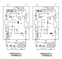
- FIG. 1 is a diagram showing a configuration of a refrigeration device 1 according to a first embodiment.
- FIG. 2 is a diagram illustrating a control relationship in the refrigeration device 1 according to the first embodiment.
- 3 is a diagram showing a flow of refrigerant under operating conditions of the refrigeration device 1 according to the first embodiment.
- FIG. 4 is a diagram illustrating the state of each solenoid valve under operating conditions of the refrigeration device 1.
- FIG. FIG. 2 is a diagram showing a processing flow of the control device 800 in the first embodiment.
- 13 is a diagram showing the flow of refrigerant when an intermediate injection blockage is detected in the refrigeration device 1 according to the second embodiment.
- FIG. 10A and 10B are diagrams illustrating the states of the solenoid valves when an intermediate injection blockage is detected in the refrigeration device 1.
- FIG. 10A and 10B are diagrams illustrating the states of the solenoid valves when an intermediate injection blockage is detected in the refrigeration device 1.
- FIG. 10A and 10B are diagrams illustrating the
- FIG. 13 is a diagram showing a flow of refrigerant when preventing liquid backflow in the refrigeration device 1 according to the third embodiment.
- FIG. 4 is a diagram illustrating the state of each solenoid valve when preventing liquid backflow in the refrigeration device 1.
- FIG. 13 is a diagram showing a flow of refrigerant when preventing a high-pressure abnormality in the refrigeration device 1 according to embodiment 4.
- 4 is a diagram for explaining the state of each solenoid valve when preventing a high-pressure abnormality in the refrigeration device 1.
- 4 is a diagram illustrating the state of each solenoid valve during operation of the refrigeration system 1.
- 4 is a diagram illustrating the state of each solenoid valve under conditions related to the operation of the refrigeration device 1.
- Fig. 1 is a diagram showing the configuration of a refrigeration device 1 according to a first embodiment.
- the refrigeration device 1 shown in Fig. 1 is a refrigeration cycle device that performs a vapor compression refrigeration cycle operation.
- the refrigeration device 1 will be described as an example of a refrigeration cycle device.
- Fig. 1 functionally shows the connection relationship and arrangement of each device in the refrigeration cycle device, and does not necessarily show the arrangement in physical space.
- the refrigeration device 1 performs cooling for a cooling load, such as a space to be cooled, such as a room, a warehouse, a showcase, or a refrigerator.
- the refrigeration device 1 in embodiment 1 has one heat source unit 100 and one load unit 600, for example, as shown in FIG. 1.
- the number of heat source units 100 and load units 600 is not particularly limited. For example, there may be two or more heat source units 100. Also, there may be two or more load units 600.
- the refrigeration device 1 has a refrigerant circuit that is configured by connecting the heat source unit 100 and the load unit 600 with a liquid refrigerant extension pipe 710 and a gas refrigerant extension pipe 720.
- the refrigerant circuit in the first embodiment has various flow paths through which the refrigerant flows that branch off from the refrigerant circuit as described below, but here, the main circuit through which the refrigerant circulates will be described as the refrigerant circuit.
- the refrigerant filled in the refrigerant circuit is carbon dioxide (CO 2 ).
- CO 2 carbon dioxide
- the refrigeration device 1 in which the refrigerant exchanges heat with air will be described.
- the refrigeration device 1 may be one in which the refrigerant exchanges heat with a fluid such as water, refrigerant, or brine.
- the load unit 600 is, for example, a unit that is installed inside a room that is the space to be cooled.
- the load unit 600 has a load side expansion valve 610, a load side solenoid valve 620, a load side heat exchanger 630, and a load side fan 640.
- the load side expansion valve 610, the load side heat exchanger 630, and the load side solenoid valve 620 are connected by piping, and are devices that make up the main part of the refrigerant circuit.
- the load side expansion valve 610 adjusts the pressure and flow rate of the refrigerant passing through the load side heat exchanger 630.
- the load side expansion valve 610 has a throttling device, such as an electronic expansion valve or a temperature-sensitive expansion valve.
- the refrigeration device 1 of the first embodiment is described as having the load unit 600 having the load side expansion valve 610, but the heat source unit 100 may have one.
- the load-side heat exchanger 630 in the first embodiment functions as an evaporator that evaporates the refrigerant by heat exchange with the indoor air.
- the load-side heat exchanger 630 is, for example, a fin-and-tube type heat exchanger having multiple heat transfer tubes and multiple fins.
- the load side solenoid valve 620 is a valve that controls the opening and closing of the passage of refrigerant in the load unit 600 based on instructions from the control device 800 described below. When the load side solenoid valve 620 is closed, no refrigerant flows into the refrigerant circuit of the load unit 600.
- the load side fan 640 is a blower that sends air to the load side heat exchanger 630 and sends the cooled air to the space to be cooled.
- the load side fan 640 is disposed near the load side heat exchanger 630.
- the load side fan 640 is composed of, for example, a centrifugal fan or a multi-blade fan.
- the load side fan 640 is driven by a motor (not shown).
- the load side fan 640 can adjust the amount of air sent to the load side heat exchanger 630 by controlling the rotation speed of the motor.
- the heat source unit 100 is a unit that supplies heat to the load unit 600.
- the heat source unit 100 has a compressor 110, an oil separator 111, a heat source side heat exchanger 120, an auxiliary heat exchanger 130, a heat source side expansion valve 140, a receiver 150, a subcooling heat exchanger 160, an accumulator 170, a check valve 171, and a heat source side fan 180.
- the compressor 110, the oil separator 111, the heat source side heat exchanger 120, the auxiliary heat exchanger 130, the heat source side expansion valve 140, the receiver 150, the subcooling heat exchanger 160, the accumulator 170, and the check valve 171 are connected by piping, and are devices that constitute the main part of the refrigerant circuit.
- the heat source unit 100 in the first embodiment is described as being one unit, but for example, the devices in the heat source unit 100 may be divided into two or more units.
- the compressor 110 compresses the sucked refrigerant and discharges it.
- the compressor 110 is, for example, a scroll compressor, a reciprocating compressor, or a vane compressor.
- the refrigeration device 1 in the first embodiment has, for example, an inverter device (not shown) and can arbitrarily change the drive frequency of the power supplied to the compressor 110. Therefore, the compressor 110 can change the rotation speed of the motor (not shown) of the compressor 110 and change the drive capacity by changing the drive frequency based on an instruction from the control device 800 described later.
- the compressor 110 in the first embodiment has an injection port 110A. Therefore, the heat source unit 100 can perform intermediate injection to flow the refrigerant into the intermediate pressure section of the compressor 110.
- the oil separator 111 separates the refrigeration oil discharged together with the gaseous refrigerant (hereinafter referred to as gas refrigerant) discharged from the compressor 110 from the gas refrigerant.
- gas refrigerant gaseous refrigerant
- the refrigeration oil separated in the oil separator 111 is returned to the compressor 110, for example, from a capillary tube (not shown) connected to the compressor 110.
- the oil separator 111 can return most of the refrigeration oil discharged from the compressor 110 to the compressor 110.
- the oil separator 111 may be integrated with the compressor 110.
- the heat source side heat exchanger 120 in the first embodiment functions as a condenser that condenses the refrigerant by heat exchange with the outdoor air.
- the heat source side heat exchanger 120 is, for example, a fin-and-tube type heat exchanger configured with multiple heat transfer tubes and multiple fins.
- the heat source side fan 180 is a blower that blows air to the heat source side heat exchanger 120.
- the heat source side fan 180 is disposed near the heat source side heat exchanger 120.
- the heat source side fan 180 is composed of, for example, a centrifugal fan or a multi-blade fan.
- the heat source side fan 180 can adjust the amount of air blown by, for example, changing the rotation speed of a motor (not shown) based on instructions from the control device 800 described below.
- the auxiliary heat exchanger 130 in the first embodiment is a heat exchanger that complements the condensing ability of the heat source side heat exchanger 120 and condenses the refrigerant passing through the refrigerant circuit.
- the auxiliary heat exchanger 130 is composed of, for example, a refrigerant-to-refrigerant heat exchanger such as a double-tube or plate heat exchanger having two refrigerant flow paths.
- the auxiliary heat exchanger 130 exchanges heat between the refrigerant flowing through the refrigerant circuit from the heat source side heat exchanger 120 toward the receiver 150 and the refrigerant flowing through the intermediate injection flow path 200.
- the refrigerant flowing through the refrigerant circuit releases heat and condenses, while the refrigerant flowing through the intermediate injection flow path 200 absorbs heat.
- the heat source side expansion valve 140 reduces the pressure of the refrigerant that has passed through the heat source side heat exchanger 120 and the auxiliary heat exchanger 130.
- the heat source side expansion valve 140 has a throttling device such as an electronic expansion valve whose opening is controlled by the control device 800 described below.
- the control device 800 described below.
- the refrigerant is carbon dioxide
- the outdoor air temperature may become higher than the supercritical temperature of the refrigerant.
- the compressor 110 is driven with a high discharge pressure, so the pressure on the high pressure side in the refrigerant circuit increases.
- the heat source side expansion valve 140 reduces the pressure of the refrigerant to meet the pressure resistance setting set for the load unit 600.
- the receiver 150 is a container that stores excess liquid refrigerant (hereinafter referred to as liquid refrigerant) that is generated in the refrigerant circuit due to, for example, the magnitude of the load in the load unit 600, the condensation temperature of the refrigerant, the outdoor air temperature, the capacity of the compressor 110, etc.
- the receiver 150 also stores refrigerant when the refrigeration device 1 performs pump-down operation. Pump-down operation is an operation in which the refrigerant in the refrigerant circuit is recovered and confined in the high-pressure side equipment and piping in the refrigerant circuit, such as the heat source unit 100.
- the subcooling heat exchanger 160 is a heat exchanger that subcools the refrigerant passing through the refrigerant circuit.
- the subcooling heat exchanger 160 is composed of a refrigerant-to-refrigerant heat exchanger such as a double-pipe or plate heat exchanger having two refrigerant flow paths.
- the subcooling heat exchanger 160 exchanges heat between the refrigerant flowing through the refrigerant circuit from the receiver 150 toward the liquid refrigerant extension pipe 710 and the refrigerant flowing through the suction injection flow path 300.
- the refrigerant flowing through the refrigerant circuit releases heat and becomes subcooled, while the refrigerant flowing through the suction injection flow path 300 absorbs heat.
- the accumulator 170 is installed on the suction side of the compressor 110.
- the accumulator 170 passes gas refrigerant through the suction side of the compressor 110 and accumulates liquid refrigerant.
- the check valve 171 is installed on the refrigerant inlet side of the accumulator 170.
- the check valve 171 is a valve that prevents refrigerant from flowing back from the accumulator 170 toward the gas refrigerant extension pipe 720.
- the heat source unit 100 in embodiment 1 has an intermediate injection flow path 200, a suction injection flow path 300, a receiver flow path 400, and a connection flow path 500 as refrigerant flow paths other than the main refrigerant circuit.
- an intermediate injection branch pipe 210 and an intermediate injection pipe 220 are installed as flow path pipes.
- a discharge temperature control valve 230 and an intermediate injection solenoid valve 240 are installed as intermediate injection control valves.
- the intermediate injection branch pipe 210 is a pipe that branches a part of the refrigerant that flows out of one flow path of the auxiliary heat exchanger 130 in the refrigerant circuit and flows to the receiver 150 from the refrigerant circuit and passes through the other flow path of the auxiliary heat exchanger 130.
- the intermediate injection pipe 220 is a pipe that flows the refrigerant that has passed through the auxiliary heat exchanger 130 or the refrigerant flowing through the connection flow path 500 described later into the intermediate pressure section of the compressor 110.
- the discharge temperature control valve 230 is a valve that serves as a throttling device that adjusts and controls the amount of refrigerant flowing through the intermediate injection branch pipe 210 and the refrigerant pressure based on instructions from the control device 800 described later, for example.
- the intermediate injection solenoid valve 240 is an opening/closing valve that controls whether or not the refrigerant is allowed to pass through the intermediate injection branch pipe 210 based on instructions from the control device 800, which will be described later.
- the suction injection flow path 300 is provided with the suction injection branch pipe 310 and the suction injection pipe 320 as flow path pipes.
- the suction injection flow path 300 is provided with the subcooling adjustment valve 330 and the suction injection solenoid valve 340 as intermediate injection control valves.
- the suction injection flow path 300 is further provided with the inlet side solenoid valve 350.
- the suction injection branch pipe 310 is a pipe that branches a part of the refrigerant that flows out of one flow path of the subcooling heat exchanger 160 in the refrigerant circuit and flows into the liquid refrigerant extension pipe 710 from the refrigerant circuit and passes through the other flow path of the subcooling heat exchanger 160.
- the suction injection pipe 320 is a pipe that flows the refrigerant that has passed through the auxiliary heat exchanger 130 into the inlet side of the accumulator 170 and the upstream side of the check valve 171, and into the suction side of the compressor 110. Therefore, here, one end of the suction injection pipe 320 is connected to the inlet side pipe of the accumulator 170.
- the subcooling adjustment valve 330 is a valve that serves as a throttle device that adjusts the amount and pressure of the refrigerant flowing through the suction injection branch pipe 310 based on, for example, an instruction from a control device 800 described later. This makes it possible to adjust the degree of subcooling of the refrigerant passing through the subcooling heat exchanger 160.
- the suction injection solenoid valve 340 is a control valve that controls whether or not the refrigerant is passed through the suction injection branch pipe 310 by opening and closing based on an instruction from the control device 800 described later.
- the inlet side solenoid valve 350 which is a suction side control valve that controls the passage of the refrigerant flowing on the suction side of the compressor 110, is an opening and closing valve that controls whether or not the refrigerant flowing through the suction injection pipe 320 and into the suction side pipe of the compressor 110 is passed based on an instruction from the control device 800 described later.
- the inlet solenoid valve 350 is a valve that opens and closes to control whether or not to pass the refrigerant flowing on the inlet side of the accumulator 170 and the upstream side of the check valve 171.
- a throttle device that adjusts the flow rate may be used as the inlet control valve, which is an opening and closing valve.
- the receiver flow path 400 has a gas vent pipe 410 and a gas solenoid valve 420.
- One end of the gas vent pipe 410 is connected to the receiver 150, and the other end is connected to the suction injection pipe 320.
- the receiver flow path 400 is a flow path that passes the gas refrigerant that is stagnating in the receiver 150 and releases it to the suction injection pipe 320.
- the gas solenoid valve 420 which serves as a gas control valve, is an opening/closing valve that controls whether or not to pass refrigerant through the gas vent pipe 410 based on instructions from the control device 800, which will be described later.
- a throttling device that adjusts the flow rate may be used as the gas control valve, which is an opening/closing valve.
- the connection flow path 500 has a connection pipe 510 and a connection solenoid valve 520.
- One end of the connection pipe 510 is connected to the intermediate injection pipe 220, and the other end is connected to the suction injection pipe 320.
- the connection solenoid valve 520 is an on-off valve that controls whether or not refrigerant is allowed to pass through the connection pipe 510 based on instructions from the control device 800 described below.
- a throttling device that adjusts the flow rate or the like may be used as the connection control valve, which is an on-off valve.
- connection solenoid valve 520 is made to be able to control the passage of the refrigerant through the connection pipe 510.
- FIG. 2 is a diagram explaining the control relationship in the refrigeration device 1 according to the first embodiment.
- the refrigeration device 1 according to the first embodiment has a control device 800.
- the control device 800 has, for example, a microcomputer.
- the microcomputer has a control unit 810 and a memory unit 820.
- the control unit 810 has, for example, a control arithmetic processing device such as a CPU (Central Processing Unit).
- the control unit 810 has an I/O port that manages the input and output of various signals.
- the discharge pressure sensor 910 detects the pressure of the refrigerant on the discharge side of the compressor 110. The pressure detected by the discharge pressure sensor 910 becomes the high-pressure pressure on the high-pressure side in the refrigerant circuit.
- the suction pressure sensor 911 detects the pressure of the refrigerant on the suction side of the compressor 110. The pressure detected by the suction pressure sensor 911 becomes the low-pressure pressure on the low-pressure side in the refrigerant circuit.
- the expansion valve pressure sensor 912 detects the pressure of the refrigerant flowing out from the heat source side expansion valve 140.
- the discharge temperature sensor 920 detects the discharge temperature of the refrigerant on the discharge side of the compressor 110.
- the discharge temperature sensor 920 has a thermistor or the like. Here, other temperature sensors described below are also assumed to have a thermistor or the like.
- the suction temperature sensor 921 detects the suction temperature of the refrigerant on the suction side of the compressor 110.
- the condenser temperature sensor 922 detects the condensation temperature of the refrigerant flowing out from the heat source side heat exchanger 120.
- the auxiliary heat exchanger temperature sensor 923 detects the auxiliary condensation temperature of the refrigerant flowing out from the auxiliary heat exchanger 130 in the refrigerant circuit.
- the intermediate injection temperature sensor 924 detects the intermediate injection temperature of the refrigerant flowing out from the auxiliary heat exchanger 130 in the intermediate injection flow path 200.
- the outdoor temperature sensor 925 detects the outdoor temperature, which is the temperature around the heat source unit 100.
- the control device 800 in the first embodiment controls the cooling capacity in the load unit 600 based on the evaporation temperature ET to improve capacity.
- the target evaporation temperature ETm of the refrigerant passing through the load side heat exchanger 630 is set low.
- the condensation capacity in the heat source unit 100 can be small. For this reason, there is no need to condense the refrigerant in the auxiliary heat exchanger 130, and there is no need to pass the refrigerant through the intermediate injection branch pipe 210.
- the control device 800 turns on (opens) the connection solenoid valve 520, and sends the refrigerant flowing through the suction injection pipe 320 through the connection pipe 510 to the intermediate injection pipe 220.
- the refrigerant that has passed through the intermediate injection pipe 220 is intermediately injected from the injection port 110A of the compressor 110. Therefore, in the heat source unit 100, intermediate injection can be performed even if the intermediate injection solenoid valve 240 is OFF (closed).
- the control device 800 turns off (closes) the intermediate injection solenoid valve 240 and the inlet side solenoid valve 350.
- the suction injection solenoid valve 340 and the gas solenoid valve 420 are in the ON (open) state.
- the inlet side solenoid valve 350 is OFF (closed)
- the refrigerant flowing through the suction injection pipe 320 can be sent to the intermediate injection pipe 220 even if the intermediate injection solenoid valve 240 and the discharge temperature control valve 230 are ON (open).
- the effect of improving performance is greater if only the refrigerant flowing through the suction injection pipe 320 is intermediately injected from the injection port 110A. For this reason, it is desirable to turn the intermediate injection solenoid valve 240 OFF (closed).
- the control device 800 turns on (opens) the intermediate injection solenoid valve 240 and passes the refrigerant through the intermediate injection branch pipe 210 and the intermediate injection pipe 220 to ensure the condensation capacity of the heat source unit 100.
- the refrigerant that has passed through the intermediate injection pipe 220 is intermediately injected from the injection port 110A of the compressor 110.
- the control device 800 also turns on (opens) the intermediate injection solenoid valve 240 and the inlet-side solenoid valve 350.
- the suction injection solenoid valve 340 and the gas solenoid valve 420 are in the ON (open) state.
- the control device 800 When the refrigerant is to be supercooled in the subcooling heat exchanger 160, the control device 800 turns on (opens) the suction injection solenoid valve 340 to pass the refrigerant through the suction injection pipe 320. At this time, the refrigerant pressure is higher in the intermediate injection flow path 200 than in the suction injection flow path 300. Therefore, when the connection solenoid valve 520 is turned on (open), the refrigerant flowing through the intermediate injection flow path 220 passes through the connection pipe 510 and flows into the suction injection pipe 320. Therefore, the subcooling heat exchanger 160 may not be able to supercool to the set degree of subcooling. Therefore, the control device 800 controls the connection solenoid valve 520 to be turned off (closed) to separate the intermediate injection flow path 200 from the suction injection flow path 300.
- FIG. 5 is a diagram showing the process flow of the control device 800 in the first embodiment. The determination of the operating conditions in the control device 800 will be described with reference to FIG. 5.
- the control device 800 determines the target evaporation temperature ETm (step S1).
- the target evaporation temperature ETm is determined based on the set temperature set for the air in the space to be cooled, the load, etc.
- the opening/closing threshold temperature is a temperature set for opening and closing the connection solenoid valve 520 based on the target evaporation temperature ETm, and is set to -15°C here.
- the opening/closing threshold temperature is not limited to -15°C and can be set arbitrarily.
- control device 800 determines that the target evaporation temperature ETm is -15°C or higher, it turns off (closes) the connection solenoid valve 520 (step S3). At this time, the control device 800 turns on (opens) the intermediate injection solenoid valve 240 and the inlet side solenoid valve 350. Furthermore, the suction injection solenoid valve 340 and the gas solenoid valve 420 are turned on (open).
- control device 800 determines that the target evaporation temperature ETm is less than -15°C, it turns on (opens) the connection solenoid valve 520 (step S4). At this time, the control device 800 turns off (closes) the intermediate injection solenoid valve 240 and the inlet side solenoid valve 350. The suction injection solenoid valve 340 and the gas solenoid valve 420 are kept on (open).
- the heat source unit 100 is configured to connect the intermediate injection pipe 220 and the suction injection pipe 320 with the connection pipe 510 in which the connection solenoid valve 520 is installed.
- the control device 800 switches the connection solenoid valve 520 between ON (open) and OFF (closed), allowing the refrigerant to pass from the suction injection pipe 320 through the connection pipe 510 to the intermediate injection pipe 220.
- This allows injection to be performed flexibly, such as intermediate injection into the compressor 110 without condensing the refrigerant in the auxiliary heat exchanger 130, and the refrigeration system 1 can operate efficiently.
- control device 800 determines that the target evaporation temperature ETm is less than the opening/closing threshold temperature of -15°C, it turns on (opens) the connection solenoid valve 520 and passes the refrigeration gas through the connection pipe 510 to perform intermediate injection. This allows the heat source unit 100 and the refrigeration device 1 having the heat source unit 100 to operate efficiently.
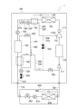
- Fig. 6 is a diagram showing the flow of refrigerant when an intermediate injection blockage is detected in the refrigeration device 1 according to embodiment 2.
- Fig. 7 is a diagram explaining the state of each solenoid valve when an intermediate injection blockage is detected in the refrigeration device 1.
- the control device 800 detects the occurrence of intermediate injection clogging, for example, based on the temperature of the refrigerant flowing through the auxiliary heat exchanger 130 detected by the auxiliary heat exchanger temperature sensor 923.
- control device 800 When the control device 800 detects a blockage in the intermediate injection, it turns on (opens) the connection solenoid valve 520 and sends the refrigerant flowing through the suction injection pipe 320 through the connection pipe 510 to the intermediate injection pipe 220. The refrigerant that has passed through the intermediate injection pipe 220 is intermediately injected from the injection port 110A of the compressor 110. At this time, the control device 800 also turns off (closes) the intermediate injection solenoid valve 240 and the inlet side solenoid valve 350. Furthermore, the suction injection solenoid valve 340 and the gas solenoid valve 420 are turned on (open).
- the control device 800 when the control device 800 detects a blockage in the intermediate injection, it turns on (opens) the connection solenoid valve 520 and performs intermediate injection of the refrigerant passing through the suction injection pipe 320. Unlike the conventional method, the refrigeration system 1 of the second embodiment can continue to operate with intermediate injection without having to stop the compressor 110, thereby improving operating efficiency.
- Fig. 8 is a diagram showing the flow of refrigerant in preventing liquid backflow in the refrigeration system 1 according to embodiment 3.
- Fig. 9 is a diagram for explaining the state of each solenoid valve in preventing liquid backflow in the refrigeration system 1.
- liquid backflow occurs in which liquid refrigerant or two-phase gas-liquid refrigerant is sucked back into the compressor 110.
- the compressor 110 may be damaged when attempting to compress the high-density liquid refrigerant inside the compressor 110.
- the control device 800 judges whether liquid backflow has occurred based on changes in the pressure, temperature, etc. of the refrigerant circuit detected by each sensor of the detection unit 900 when the compressor 110 is started.
- the control device 800 judges that liquid backflow has occurred, it turns the suction injection solenoid valve 340 OFF (closed) and turns the gas solenoid valve 420 ON (open).
- the intermediate injection solenoid valve 240 and the inlet side solenoid valve 350 are ON (open), and the connection solenoid valve 520 is OFF (closed).
- the gas refrigerant in the receiver 150 By releasing the gas refrigerant in the receiver 150 to the suction injection piping 320, the gas refrigerant can be discharged from the receiver 150 and the liquid refrigerant can be stored in the receiver 150. Therefore, the amount of liquid refrigerant circulating in the refrigerant circuit can be reduced.
- the supercooling adjustment valve 330 is closed when liquid backflow occurs, the liquid backflow in the compressor 110 can be eliminated.
- the subcooling adjustment valve 330 slowly closes the intake injection flow path 300, the liquid backflow may not be eliminated, resulting in an abnormal stop, so it is desirable to install the intake injection solenoid valve 340.
- control device 800 determines that liquid backflow is occurring, it turns on (opens) the gas solenoid valve 420 to allow liquid refrigerant to accumulate in the receiver 150. This prevents liquid refrigerant from returning to the suction side of the compressor 110, improving liquid backflow resistance.
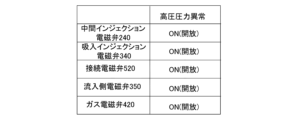
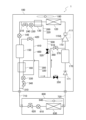
- Fig. 10 is a diagram showing the flow of refrigerant when preventing a high-pressure abnormality in the refrigeration system 1 according to embodiment 4.
- Fig. 11 is a diagram for explaining the state of each solenoid valve when preventing a high-pressure abnormality in the refrigeration system 1.
- a high-pressure abnormality stop pressure is set in the refrigeration device 1, and when the control device 800 determines that the high-pressure pressure in the refrigerant circuit is equal to or higher than the high-pressure abnormality stop pressure, it stops operation of the heat source unit 100.
- the control device 800 normally controls the heat source unit 100 so as not to shut down due to a high-pressure abnormality. Nevertheless, during transient operation, the high-pressure pressure in the refrigerant circuit may rise abnormally.
- the control device 800 determines based on the high-pressure abnormality stop pressure that the pressure is equal to or greater than the high-pressure abnormality set pressure, which is set to be lower than the high-pressure abnormality stop pressure, it turns on (opens) the connection solenoid valve 520.
- the connection solenoid valve 520 is turned on (opens)
- the refrigerant on the high-pressure side flows from the connection pipe 510 to the low-pressure side in the refrigerant circuit.
- the control device 800 also turns on (opens) the other solenoid valves.
- the control device 800 when the control device 800 determines that the high-pressure side pressure is equal to or greater than the high-pressure abnormality setting pressure, it turns on (opens) the connection solenoid valve 520. This allows the refrigerant on the high-pressure side in the refrigerant circuit to escape to the low-pressure side, suppressing an increase in the high-pressure side pressure. This prevents the pressure in the refrigerant circuit from becoming abnormal due to a high-pressure abnormality stop pressure, and prevents an abnormal stop of the heat source unit 100.
- FIG. 12 is a diagram showing the configuration of the refrigeration device 1 according to the fifth embodiment.
- the refrigeration device 1 in the fifth embodiment has a different configuration of the suction injection flow path 300 from that in Fig. 1.
- the refrigeration device 1 in the fifth embodiment is configured such that the suction injection pipe 320 is not only connected to the pipe upstream of the check valve 171, but also to the pipe on the outflow side of the accumulator 170 by branching it, and an outflow branch pipe 360 having an outflow solenoid valve 370 installed therein is connected thereto.
- the suction injection flow path 300 further includes an outlet branch pipe 360 and an outlet solenoid valve 370.
- the outlet branch pipe 360 has one end connected to the suction injection pipe 320 and the other end connected to a pipe between the outlet side of the accumulator 170 and the suction side of the compressor 110. Therefore, the refrigerant that passes through the outlet branch pipe 360 from the suction injection pipe 320 flows to the outlet side of the accumulator 170 and the suction side of the compressor 110.
- the outlet solenoid valve 370 which is a suction side control valve that controls the passage of the refrigerant flowing to the suction side of the compressor 110, is an opening/closing valve that controls whether or not to pass the refrigerant that passes through the suction injection pipe 320 and flows to the suction side pipe of the compressor 110, similar to the inlet solenoid valve 350, based on instructions from the control device 800 described later.
- the outflow side solenoid valve 370 is a valve that controls whether or not to pass the refrigerant that passes through the outflow side branch pipe 360 and flows to the outflow side of the accumulator 170.
- a throttle device that adjusts the flow rate may be used as an outflow side control valve that is an opening and closing valve.
- FIG. 13 is a diagram showing the flow of refrigerant during operation of the refrigeration device 1 according to embodiment 5.
- FIG. 14 is a diagram explaining the state of each solenoid valve during operation of the refrigeration device 1.
- the stator (not shown) mounted in the shell of the compressor 110 is immersed in the refrigeration oil, causing the temperature of the refrigeration oil to rise.
- high-temperature refrigeration oil is returned from the oil separator 111.
- high-temperature refrigerant is sucked into the compressor 110 on the suction side of the compressor 110. If the refrigerant temperature remains high for a long period of time, it can lead to damage to parts in the shell of the compressor 110.
- control device 800 determines that the suction temperature detected by the suction temperature sensor 921 is equal to or higher than the suction threshold temperature, it turns on (opens) the outlet solenoid valve 370 and turns off (closes) the inlet solenoid valve 350 in the suction injection flow path 300. As a result, refrigerant at a lower temperature than the refrigerant flowing out from the accumulator 170 is sucked into the compressor 110 via the outlet branch pipe 360.
- a gas-liquid two-phase refrigerant flows through the suction injection flow path 300.
- the refrigerant suction-injected through the inlet-side solenoid valve 350 passes through the accumulator 170, so that gas refrigerant is suctioned into the compressor 110, and the sensible heat of the refrigerant cools the compressor 110.
- the refrigerant suction-injected through the outlet-side solenoid valve 370 is a gas-liquid two-phase refrigerant, so that the refrigerant's latent heat is also included in the refrigerant to cool the compressor 110. This makes it possible to efficiently lower the temperature inside the compressor 110.
- the intermediate injection solenoid valve 240, the suction injection solenoid valve 340, and the gas solenoid valve 420 are in the ON (open) state, and the connection solenoid valve 520 is in the OFF (closed) state.
- Fig. 15 is a diagram showing the flow of refrigerant under conditions related to the operation of the refrigeration system 1 according to embodiment 6.
- Fig. 16 is a diagram explaining the state of each solenoid valve under conditions related to the operation of the refrigeration system 1.
- the configuration of the refrigeration system 1 according to embodiment 6 is similar to that of the refrigeration system 1 according to embodiment 5.
- the liquid refrigerant accumulated in the receiver 150 evaporates, and the refrigerant pressure in the heat source unit 100, particularly on the high-pressure side of the refrigerant circuit that is the discharge side of the compressor 110, may rise. At this time, if there is a lot of refrigerant in the heat source unit 100, the design pressure resistance preset for the heat source unit 100 may be exceeded.
- control device 800 determines that the high pressure detected by the discharge pressure sensor 910 is equal to or higher than the stop setting pressure set at a pressure value lower than the design withstand pressure, it turns on (opens) the outflow side solenoid valve 370.
- the outflow side solenoid valve 370 is turned on (opens)
- the refrigerant on the high pressure side flows to the low pressure side in the refrigerant circuit on the discharge side of the compressor 110.
- the accumulator 170 installed on the low pressure side increases the volume of the refrigerant stored therein, and the pressure on the high pressure side also decreases.
- control device 800 turns on (opens) the intermediate injection solenoid valve 240, the suction injection solenoid valve 340, and the gas solenoid valve 420, and ensures the volume of the piping of each flow path.
- the connection solenoid valve 520 is turned off (closed).
- the pressure on the high-pressure side may not decrease even if the outlet solenoid valve 370 is turned ON (opened). Therefore, when the control device 800 determines that the high-pressure pressure will not fall below the stop-time set pressure within a predetermined set time, it also turns ON (opens) the inlet solenoid valve 350. By turning ON (opening) the inlet solenoid valve 350, refrigerant is also released to the gas refrigerant extension piping 720 and the load unit 600, and the pressure on the high-pressure side can be reduced throughout the entire refrigerant circuit.
- the inlet side solenoid valve 350 is installed on the gas refrigerant extension pipe 720 side, which is upstream of the check valve 171, so the suction pressure sensor 911 detects an increase in low pressure. Therefore, when the control device 800 determines that the low pressure detected by the suction pressure sensor 911 is equal to or greater than the predetermined low pressure threshold, it turns on the thermostat and operates the refrigeration device 1. This makes it possible to reduce the pressure on the high pressure side of the refrigerant circuit.
- the control device 800 determines that the high-pressure pressure is equal to or higher than the stop-time set pressure while the heat source unit 100 of the refrigeration device 1 is stopped, it turns on (opens) the outlet side solenoid valve 370 to release the refrigerant to the low-pressure side of the refrigerant circuit.
- This makes it possible to prevent the refrigerant pressure from becoming abnormally high in a part of the refrigerant circuit. This therefore protects the heat source unit 100 and the refrigeration device 1 and improves reliability.
- the inlet side solenoid valve 350 can also be turned on (opened) to reduce the high-pressure side pressure throughout the entire refrigerant circuit.
- the heat source unit 100 is applied to the refrigeration device 1, but it can also be applied to other refrigeration cycle devices, such as a refrigerator.
- Refrigeration device 100 Heat source unit, 110 Compressor, 110A Injection port, 111 Oil separator, 120 Heat source side heat exchanger, 130 Auxiliary heat exchanger, 140 Heat source side expansion valve, 150 Receiver, 160 Subcooling heat exchanger, 170 Accumulator, 171 Check valve, 180 Heat source side fan, 200 Intermediate injection flow path, 210 Intermediate injection branch pipe, 220 Intermediate injection pipe, 230 Discharge temperature control valve, 240 Intermediate injection solenoid valve, 300 Intake injection flow path, 310 Intake injection branch pipe, 320 Intake injection pipe, 330 Subcooling control valve, 340 Intake injection solenoid valve, 350 Inlet side solenoid valve, 36 0 Outlet branch pipe, 370 Outlet solenoid valve, 400 Receiver flow path, 410 Gas vent pipe, 420 Gas solenoid valve, 500 Connection flow path, 510 Connection pipe, 520 Connection solenoid valve, 600 Load unit, 610 Load expansion valve, 620 Load solenoid valve, 630 Load heat exchanger, 640
Landscapes
- Engineering & Computer Science (AREA)
- Physics & Mathematics (AREA)
- Mechanical Engineering (AREA)
- Thermal Sciences (AREA)
- General Engineering & Computer Science (AREA)
- Compression-Type Refrigeration Machines With Reversible Cycles (AREA)
Priority Applications (2)
| Application Number | Priority Date | Filing Date | Title |
|---|---|---|---|
| JP2025563204A JPWO2025126455A1 (https=) | 2023-12-15 | 2023-12-15 | |
| PCT/JP2023/045031 WO2025126455A1 (ja) | 2023-12-15 | 2023-12-15 | 熱源ユニットおよび冷凍サイクル装置 |
Applications Claiming Priority (1)
| Application Number | Priority Date | Filing Date | Title |
|---|---|---|---|
| PCT/JP2023/045031 WO2025126455A1 (ja) | 2023-12-15 | 2023-12-15 | 熱源ユニットおよび冷凍サイクル装置 |
Publications (1)
| Publication Number | Publication Date |
|---|---|
| WO2025126455A1 true WO2025126455A1 (ja) | 2025-06-19 |
Family
ID=96056737
Family Applications (1)
| Application Number | Title | Priority Date | Filing Date |
|---|---|---|---|
| PCT/JP2023/045031 Pending WO2025126455A1 (ja) | 2023-12-15 | 2023-12-15 | 熱源ユニットおよび冷凍サイクル装置 |
Country Status (2)
| Country | Link |
|---|---|
| JP (1) | JPWO2025126455A1 (https=) |
| WO (1) | WO2025126455A1 (https=) |
Citations (3)
| Publication number | Priority date | Publication date | Assignee | Title |
|---|---|---|---|---|
| WO2016079805A1 (ja) * | 2014-11-18 | 2016-05-26 | 三菱電機株式会社 | スクロール圧縮機及び冷凍サイクル装置 |
| JP2022027894A (ja) * | 2020-07-08 | 2022-02-14 | 三菱電機株式会社 | 冷凍装置 |
| JP2022177312A (ja) * | 2019-09-09 | 2022-11-30 | 三菱電機株式会社 | 室外ユニットおよび冷凍サイクル装置 |
-
2023
- 2023-12-15 JP JP2025563204A patent/JPWO2025126455A1/ja active Pending
- 2023-12-15 WO PCT/JP2023/045031 patent/WO2025126455A1/ja active Pending
Patent Citations (3)
| Publication number | Priority date | Publication date | Assignee | Title |
|---|---|---|---|---|
| WO2016079805A1 (ja) * | 2014-11-18 | 2016-05-26 | 三菱電機株式会社 | スクロール圧縮機及び冷凍サイクル装置 |
| JP2022177312A (ja) * | 2019-09-09 | 2022-11-30 | 三菱電機株式会社 | 室外ユニットおよび冷凍サイクル装置 |
| JP2022027894A (ja) * | 2020-07-08 | 2022-02-14 | 三菱電機株式会社 | 冷凍装置 |
Also Published As
| Publication number | Publication date |
|---|---|
| JPWO2025126455A1 (https=) | 2025-06-19 |
Similar Documents
| Publication | Publication Date | Title |
|---|---|---|
| JP6292480B2 (ja) | 冷凍装置 | |
| JP5992089B2 (ja) | 空気調和装置 | |
| US20110174005A1 (en) | Refrigerating apparatus | |
| US11149999B2 (en) | Refrigeration cycle apparatus having foreign substance release control | |
| JP6715655B2 (ja) | 冷却装置 | |
| US12038213B2 (en) | Refrigeration cycle apparatus | |
| CN111919073B (zh) | 制冷装置 | |
| US11512880B2 (en) | Refrigeration cycle device | |
| US11598559B2 (en) | Heat source-side unit and refrigeration apparatus | |
| JP4069947B2 (ja) | 冷凍装置 | |
| EP2314954B1 (en) | Refrigeration device | |
| CN110494702B (zh) | 制冷循环装置 | |
| KR101692243B1 (ko) | 캐스캐이드 사이클을 이용한 히트 펌프 | |
| US11512876B2 (en) | Refrigeration apparatus | |
| JP4868049B2 (ja) | 冷凍装置 | |
| JP2007010220A (ja) | 冷凍装置及びその冷凍装置を備えた冷蔵庫 | |
| WO2025126455A1 (ja) | 熱源ユニットおよび冷凍サイクル装置 | |
| JP7750099B2 (ja) | 空気調和機 | |
| JP2009293887A (ja) | 冷凍装置 | |
| WO2023067807A1 (ja) | 二元冷凍装置 | |
| CN118435011A (zh) | 远程冷凝器单元、制冷循环装置以及制冷装置 | |
| WO2017098655A1 (ja) | 冷凍サイクル装置 | |
| JP6704513B2 (ja) | 冷凍サイクル装置 | |
| JP6381712B2 (ja) | 冷凍サイクル装置 | |
| KR100743719B1 (ko) | 멀티형 공기조화기의 고압상승 방지방법 |
Legal Events
| Date | Code | Title | Description |
|---|---|---|---|
| 121 | Ep: the epo has been informed by wipo that ep was designated in this application |
Ref document number: 23961518 Country of ref document: EP Kind code of ref document: A1 |
|
| ENP | Entry into the national phase |
Ref document number: 2025563204 Country of ref document: JP Kind code of ref document: A |