WO2025121015A1 - 水処理システム、水質測定装置、および水質測定方法 - Google Patents
水処理システム、水質測定装置、および水質測定方法 Download PDFInfo
- Publication number
- WO2025121015A1 WO2025121015A1 PCT/JP2024/037517 JP2024037517W WO2025121015A1 WO 2025121015 A1 WO2025121015 A1 WO 2025121015A1 JP 2024037517 W JP2024037517 W JP 2024037517W WO 2025121015 A1 WO2025121015 A1 WO 2025121015A1
- Authority
- WO
- WIPO (PCT)
- Prior art keywords
- water
- concentration
- concentrated
- treated
- measuring instrument
- Prior art date
- Legal status (The legal status is an assumption and is not a legal conclusion. Google has not performed a legal analysis and makes no representation as to the accuracy of the status listed.)
- Pending
Links
Images














Classifications
-
- B—PERFORMING OPERATIONS; TRANSPORTING
- B01—PHYSICAL OR CHEMICAL PROCESSES OR APPARATUS IN GENERAL
- B01D—SEPARATION
- B01D61/00—Processes of separation using semi-permeable membranes, e.g. dialysis, osmosis or ultrafiltration; Apparatus, accessories or auxiliary operations specially adapted therefor
- B01D61/02—Reverse osmosis; Hyperfiltration ; Nanofiltration
- B01D61/08—Apparatus therefor
-
- B—PERFORMING OPERATIONS; TRANSPORTING
- B01—PHYSICAL OR CHEMICAL PROCESSES OR APPARATUS IN GENERAL
- B01D—SEPARATION
- B01D61/00—Processes of separation using semi-permeable membranes, e.g. dialysis, osmosis or ultrafiltration; Apparatus, accessories or auxiliary operations specially adapted therefor
- B01D61/02—Reverse osmosis; Hyperfiltration ; Nanofiltration
- B01D61/12—Controlling or regulating
-
- B—PERFORMING OPERATIONS; TRANSPORTING
- B01—PHYSICAL OR CHEMICAL PROCESSES OR APPARATUS IN GENERAL
- B01D—SEPARATION
- B01D61/00—Processes of separation using semi-permeable membranes, e.g. dialysis, osmosis or ultrafiltration; Apparatus, accessories or auxiliary operations specially adapted therefor
- B01D61/42—Electrodialysis; Electro-osmosis ; Electro-ultrafiltration; Membrane capacitive deionization
- B01D61/44—Ion-selective electrodialysis
-
- B—PERFORMING OPERATIONS; TRANSPORTING
- B01—PHYSICAL OR CHEMICAL PROCESSES OR APPARATUS IN GENERAL
- B01D—SEPARATION
- B01D61/00—Processes of separation using semi-permeable membranes, e.g. dialysis, osmosis or ultrafiltration; Apparatus, accessories or auxiliary operations specially adapted therefor
- B01D61/42—Electrodialysis; Electro-osmosis ; Electro-ultrafiltration; Membrane capacitive deionization
- B01D61/44—Ion-selective electrodialysis
- B01D61/46—Apparatus therefor
- B01D61/48—Apparatus therefor having one or more compartments filled with ion-exchange material, e.g. electrodeionisation
-
- C—CHEMISTRY; METALLURGY
- C02—TREATMENT OF WATER, WASTE WATER, SEWAGE, OR SLUDGE
- C02F—TREATMENT OF WATER, WASTE WATER, SEWAGE, OR SLUDGE
- C02F1/00—Treatment of water, waste water, or sewage
-
- C—CHEMISTRY; METALLURGY
- C02—TREATMENT OF WATER, WASTE WATER, SEWAGE, OR SLUDGE
- C02F—TREATMENT OF WATER, WASTE WATER, SEWAGE, OR SLUDGE
- C02F1/00—Treatment of water, waste water, or sewage
- C02F1/42—Treatment of water, waste water, or sewage by ion-exchange
-
- C—CHEMISTRY; METALLURGY
- C02—TREATMENT OF WATER, WASTE WATER, SEWAGE, OR SLUDGE
- C02F—TREATMENT OF WATER, WASTE WATER, SEWAGE, OR SLUDGE
- C02F1/00—Treatment of water, waste water, or sewage
- C02F1/44—Treatment of water, waste water, or sewage by dialysis, osmosis or reverse osmosis
-
- C—CHEMISTRY; METALLURGY
- C02—TREATMENT OF WATER, WASTE WATER, SEWAGE, OR SLUDGE
- C02F—TREATMENT OF WATER, WASTE WATER, SEWAGE, OR SLUDGE
- C02F1/00—Treatment of water, waste water, or sewage
- C02F1/46—Treatment of water, waste water, or sewage by electrochemical methods
- C02F1/469—Treatment of water, waste water, or sewage by electrochemical methods by electrochemical separation, e.g. by electro-osmosis, electrodialysis, electrophoresis
-
- Y—GENERAL TAGGING OF NEW TECHNOLOGICAL DEVELOPMENTS; GENERAL TAGGING OF CROSS-SECTIONAL TECHNOLOGIES SPANNING OVER SEVERAL SECTIONS OF THE IPC; TECHNICAL SUBJECTS COVERED BY FORMER USPC CROSS-REFERENCE ART COLLECTIONS [XRACs] AND DIGESTS
- Y02—TECHNOLOGIES OR APPLICATIONS FOR MITIGATION OR ADAPTATION AGAINST CLIMATE CHANGE
- Y02A—TECHNOLOGIES FOR ADAPTATION TO CLIMATE CHANGE
- Y02A20/00—Water conservation; Efficient water supply; Efficient water use
- Y02A20/124—Water desalination
- Y02A20/131—Reverse-osmosis
Definitions
- the present invention relates to a water treatment system, a water quality measuring device, and a water quality measuring method.
- pure water including ultrapure water
- organic matter, ionic components, fine particles, bacteria, etc. are used as cleaning water.
- the quality of the pure water must always be maintained at a stable high purity. To meet this requirement, it is preferable to manage the operating conditions in the pure water manufacturing process while checking the quality of the pure water on-site using online water quality instruments.
- Patent Document 1 discloses a method of measuring the water quality on the inlet side of a water treatment device and predicting (simulating) the concentration of components that will leak to the outlet side of the water treatment device based on this measured value and a predetermined removal rate of the water treatment device.
- Patent Document 2 describes a continuous monitoring device for test water. This monitoring device has a reverse osmosis (RO) membrane separation means, a return means, an analysis means, and a calculation means.
- the return means returns a part of the concentrated water of the RO membrane separation means to the inlet side of the RO membrane separation means.
- the analysis means measures the concentration of the analyte in the remaining concentrated water.
- the calculation means calculates the concentration of the analyte in the test water based on the measurement result.
- RO reverse osmosis
- the analysis means can measure the concentration of the analyte in the test water at the ultrapure water level.
- the flow rate of the membrane surface of the RO membrane is increased. Therefore, the analyte in the test water can be concentrated at a high concentration rate.
- the water quality at the inlet side of the water treatment device is measured, so it is difficult to accurately judge the deterioration of the performance of the water treatment device itself.
- the device described in Patent Document 2 is a device for measuring the quality of test water. Therefore, it is difficult to continuously measure the quality of pure water discharged from a water treatment device on-site. Even if the device described in Patent Document 2 is applied to a water treatment device and configured to measure the quality of pure water on-site, it is difficult to accurately measure the quality of the pure water discharged from the water treatment device because a portion of the concentrated water is circulated.
- the object of the present invention is to provide a water treatment system and water quality measuring device that can accurately detect the water quality of treated water at a pure water level on-site.
- a water treatment device that treats water to be treated to produce treated water having a resistivity of 0.10 M ⁇ cm or more;
- a concentrating device disposed separately from the water treatment device, through which at least a portion of the treated water produced by the water treatment device passes and which concentrates a specific component in the at least a portion of the treated water;
- a measuring instrument for continuously measuring the concentration of the specific component in the concentrated water concentrated by the concentrating device;
- a water treatment system comprising: a monitoring unit that monitors the water quality of the treated water based on the measured values obtained by the measuring instrument.
- a water quality measuring device used to monitor the quality of treated water produced by a water treatment device that treats water to be treated and produces treated water having a resistivity of 0.10 M ⁇ cm or more, a concentrating device through which at least a portion of the treated water is passed and which concentrates a specific component in the at least a portion of the treated water;
- the concentrator is an electric concentrator, and a water quality measuring device is provided.
- the quality of treated water at a pure water level can be accurately detected on-site.
- FIG. 1 is a block diagram showing a configuration of a water treatment system according to a first embodiment of the present invention.
- FIG. 4 is a block diagram showing a configuration of a water treatment system according to a second embodiment of the present invention.
- FIG. 1 is a schematic diagram showing a first example of an electrical concentrator.
- FIG. 2 is a schematic diagram showing a second example of an electrical concentrator.
- FIG. 13 is a schematic diagram showing a third example of an electrical concentrator.
- FIG. 13 is a schematic diagram showing a fourth example of an electrical concentrator.
- FIG. 13 is a schematic diagram showing a fifth example of an electrical concentrator.
- FIG. 13 is a schematic diagram showing a sixth example of an electrical concentrator.
- FIG. 13 is a diagram for explaining an example of a method for calculating the concentration rate of the concentrating device 2.
- FIG. 13 is a diagram for explaining another example of a method for calculating the concentration rate of the concentrating device 2.
- FIG. 1 is a block diagram showing a water treatment system according to a first embodiment;
- FIG. 1 is a diagram for explaining the change in silica concentration before and after adjustment.
- FIG. 11 is a block diagram showing a water treatment system according to a second embodiment.
- FIG. 1 is a diagram for explaining the change in silica concentration before and after chemical regeneration.
- FIG. 11 is a block diagram showing a water treatment system according to a third embodiment.
- FIG. 1 shows the change in silica concentration.
- FIG. 13 is a block diagram showing a water treatment system according to a fourth embodiment.
- FIG. 13 is a graph showing changes in boron concentration.
- FIG. 13 is a block diagram showing a water treatment system according to a fifth embodiment.
- FIG. 13 is a graph showing changes in boron concentration.
- FIG. 13 is a block diagram showing a water treatment system according to a sixth embodiment.
- FIG. 1 shows changes in IC concentration.
- FIG. 13 is a diagram for explaining an example of a method for calculating a concentration ratio of an RO membrane separation device.
- FIG. 1 is a diagram showing the measurement results of sodium and silica.
- FIG. 13 is a diagram showing an example of measured values of a silica meter in the absence of a concentrator.
- FIG. 13 is a diagram showing an example of measured values of a silica meter when a concentrator is provided.
- FIG. 1 shows changes in IC concentration.
- FIG. 13 is a diagram for explaining an example of a method for calculating a concentration ratio of an RO membrane separation device.
- FIG. 1 is
- FIG. 11 is a block diagram showing a configuration of a water treatment system according to a third embodiment of the present invention.
- FIG. 2 is a schematic diagram showing a configuration example of a concentrating device.
- FIG. 2 is a schematic diagram showing another configuration example of a concentrating device.
- FIG. 2 is a block diagram showing a configuration of a water treatment system of a comparative example.
- FIG. 28 is a diagram showing an example of measurement data from the water quality measuring device shown in FIG. 27.
- FIG. 11 is a block diagram showing a configuration of a water treatment system according to a fourth embodiment of the present invention.
- FIG. 1 is a block diagram showing the configuration of a water treatment system according to a first embodiment of the present invention.
- the water treatment system of this embodiment includes a water treatment device 1, a water quality measuring device 10, and a monitoring unit 11.
- the water treatment device 1 treats water to be treated 1a to produce treated water 1b.
- the treated water 1b is, for example, pure water (or ultrapure water), and its specific resistance is, for example, 0.10 M ⁇ cm or more (conductivity 10 ⁇ S/cm or less).
- the treated water 1b produced by the water treatment device 1 is branched into two, one of which is supplied to a use point or a downstream treatment device as treated water 1c, and the other is supplied to the water quality measuring device 10 as treated water 1d.
- the water treatment device 1 includes, for example, at least one of a reverse osmosis (RO) membrane separation device, a regenerative ion exchange resin device, a non-regenerative ion exchange resin device, and an electric regenerative deionized water production device (EDI). Note that the water treatment device 1 may include other devices for water treatment as long as it can produce treated water with a specific resistance value of 0.10 M ⁇ cm or more.
- RO reverse osmosis
- EDI electric regenerative deionized water production device
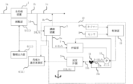
- the water quality measuring device 10 has a concentrating device 2 and a measuring instrument 3.
- the concentrating device 2 is configured to pass treated water 1d, which is a part of treated water 1b produced by the water treatment device 1.
- the concentrating device 2 concentrates a specific component (a component to be concentrated) contained in the treated water 1d.
- the concentrating device 2 supplies a signal indicating the concentration ratio to the monitoring unit 11.
- the concentrating device 2 is, for example, a desalination device that produces at least concentrated water 2a and desalted treated water 2b.
- the removal rate (densification rate) of the specific component is 90% or more, preferably 95% or more, and more preferably 99% or more.
- the concentration ratio of the concentrated water 2a to the water to be treated 1d is 3 times or more, preferably 10 times or more, and more preferably 20 times or more. In this embodiment, the removal rate (densification rate) is 90% or more, and the concentration ratio is in the range of 3 to 20 times.
- the concentrated water 2a is supplied to the measuring instrument 3.
- the desalted treated water 2b is merged with the treated water 1c and supplied to the use point.
- the concentrated water that has passed through the measuring instrument 3 is basically discarded, but from the viewpoint of utilization efficiency, it may be returned to the upstream or downstream of the water treatment device 1, or may be used in another system. Note that the desalinated treated water 2b may be sent in a separate system without merging with the treated water 1c, in cases where the piping connections are time-consuming or the configuration is complicated.
- the measuring instrument 3 continuously measures the concentration of a specific component contained in the concentrated water 2a discharged from the concentrating device 2.
- the measuring instrument 3 supplies a signal indicating the measured value to the monitoring unit 11.
- the measuring instrument 3 is, for example, an instrument that measures the concentration of any of the following components: silica, boron, metal ions (sodium, aluminum, calcium, magnesium, etc.), carbonate, IC (inorganic carbon), and TOC (total organic carbon). Note that these instruments are only examples, and instruments that measure the concentration of other components may also be used.
- the monitoring unit 11 monitors the water quality of the treated water 1b based on the measured value of the measuring instrument 3.
- the monitoring unit 11 has a treated water concentration calculation unit 4, an adjustment unit 5, and an alarm output unit 6.
- the treated water concentration calculation unit 4 calculates the concentration value (conversion value) of a specific component in the treated water 1b by dividing the measured value of the measuring instrument 3 by the concentration ratio of the concentrating device 2.
- the concentration value (conversion value) is supplied to the adjustment unit 5 and the alarm output unit 6.
- the concentration ratio may be a preset value, or may be a value constantly calculated from the values of each flow meter installed in the concentrating device 2.
- the adjustment unit 5 adjusts the treatment state of the water treatment device 1 for a specific component based on the concentration value (conversion value) of the specific component in the treated water 1b.
- the adjustment unit 5 is configured to be able to perform at least one of the following adjustments, for example: flow rate adjustment, chemical regeneration, ion exchange resin replacement, current adjustment, water temperature adjustment, and pH adjustment. These adjustments will be described in detail in the examples below. Note that these adjustments may also be performed by an administrator.
- the alarm output unit 6 outputs an alarm based on the concentration value (converted value) of a specific component in the treated water 1b. For example, the alarm output unit 6 outputs an alarm when the concentration value (converted value) of a specific component in the treated water 1b exceeds a threshold value or when a trend indicating a decrease in the treatment performance for the specific component is detected.
- the alarm output unit 6 may include a display device that displays a message indicating an alarm, a speaker that outputs an alarm sound, etc.
- the concentration of the specific component in the pure water level treated water 1b is lower than the lower limit of the concentration that can be measured by the measuring instrument 3, it is difficult to accurately measure the concentration of the specific component in the treated water 1b using the measuring instrument 3.
- the measuring instrument 3 measures the concentration of the specific component in the concentrated water 2a obtained by concentrating the treated water 1d, which is a part of the treated water 1b.
- the concentration of the specific component in the concentrated water 2a is higher than the lower limit of the concentration that can be measured by the measuring instrument 3. Therefore, the measuring instrument 3 can be used to accurately measure the concentration of the specific component in the concentrated water 2a.
- the measured value of the concentrated water 2a can be converted into the concentration value of the specific component in the treated water 1b by dividing it by the concentration ratio of the concentrating device 2. This makes it possible to obtain the concentration (converted value) of the specific component in the pure water level treated water 1b.
- the water treatment device 1 can be operated and managed continuously and stably. For example, if a trend indicating a decrease in the treatment performance of the water treatment device 1 for a specific component (e.g., an upward trend) is detected, a performance recovery process for the water treatment device 1 can be immediately carried out. This stabilizes the performance of the water treatment device 1, and as a result, the water quality of the treated water 1b can be maintained stably.
- a trend indicating a decrease in the treatment performance of the water treatment device 1 for a specific component e.g., an upward trend
- the quality of the treated water produced by the water treatment equipment cannot be analyzed on-site immediately, so even if a problem such as a decrease in the performance of the water treatment equipment occurs, it takes time to determine the cause. Furthermore, if the performance of the water treatment equipment decreases before the cause is determined, the equipment will continue to operate in that state. In this case, the treated water may no longer meet the water quality required for washing water in semiconductor manufacturing equipment or liquid crystal manufacturing equipment. If treated water that does not meet the required water quality is used as washing water, it may cause fatal damage to the semiconductor manufacturing equipment or liquid crystal manufacturing equipment.
- the present embodiment since it is possible to perform on-site water quality analysis of the treated water, it is possible to immediately detect and deal with problems such as a decrease in performance of the water treatment device 1. Therefore, it is possible to stably provide treated water that meets the required water quality for cleaning water.
- the performance recovery treatment of the water treatment device was carried out well in advance.
- the regeneration frequency was generally set well in advance and was carried out before the performance degradation progressed.
- the performance recovery process can be performed at an optimal timing. For example, in a regenerative ion exchange resin device, by detecting a tendency of performance degradation at an early stage, it becomes possible to continue operation until the very limit of performance degradation, and it becomes possible to approach an optimal regeneration frequency.
- the water quality can be analyzed at the time of sampling, but it is difficult to grasp fluctuations in water quality.
- this embodiment by constantly monitoring the water quality on-site using online instruments, it is possible to grasp fluctuations in water quality and implement more appropriate operation management. Furthermore, according to this embodiment, since a clean environment and sampling equipment are not required, it is possible to reduce facility costs.
- the adjustment unit 5 is configured to perform a performance recovery process for the water treatment device 1, but this is not limited to the above.
- An administrator may perform the necessary work for the performance recovery process in response to an alarm (message or alarm sound) from the alarm output unit 6.
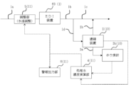
- Second Embodiment Fig. 2 is a block diagram showing the configuration of a water treatment system according to a second embodiment of the present invention.
- the water treatment system according to this embodiment has a water treatment device 1, a water quality measuring device 10, and a monitoring unit 11.
- the water treatment device 1 and the monitoring unit 11 are the same as those described in the first embodiment.
- the water quality measuring device 10 is also basically the same as that described in the first embodiment, but differs from the first embodiment in that the concentrating device 2 is configured to pass treated water 1b produced by the water treatment device 1 through it.
- the same components are denoted by the same reference numerals, and detailed description thereof will be omitted.
- the concentrating device 2 concentrates a specific component (a component to be concentrated) contained in the treated water 1b.
- the concentrating device 2 is, for example, a desalination device that produces at least concentrated water 2a and desalted water 2b.
- the specific configuration of the concentrating device 2 is as described in the first embodiment.
- the concentrated water 2a discharged from the concentrating device 2 is supplied to the measuring instrument 3.
- the desalted water 2b discharged from the concentrating device 2 is supplied to a point of use or a downstream treatment device.
- the water treatment system of this embodiment also exhibits the same effects as those described in the first embodiment. Moreover, in the water treatment system of the first embodiment, the concentrating device 2 is provided in the branch line of the treated water. In contrast, in the water treatment system of this embodiment, the concentrating device 2 is provided in the main line of the treated water, and no branch line is provided. This allows for a slimmer facility compared to the first embodiment. In other words, when the concentrating device is installed in the main line, the concentrated water device needs to have the capacity to pass all of the treated water in the main line. Therefore, while the water treatment system of the first embodiment is suitable for a large water treatment device 1, the water treatment system of this embodiment is suitable for a small water treatment device 1.
- the concentrator 2 is preferably an electrical regeneration type deionized water production device (hereinafter referred to as an electrical concentrator).
- an electrical concentrator a cation exchange membrane and an anion exchange membrane are arranged between a cathode and an anode.
- a cationic component concentration chamber is provided on the cathode side of the cation exchange membrane, and a desalting chamber is provided on the anode side, and/or an anionic component concentration chamber is provided on the anode side of the anion exchange membrane, and a desalting chamber is provided on the cathode side.
- At least the desalting chamber is filled with ion exchange resin, and continuous concentration is performed by passing a direct current between the cathode and anode.
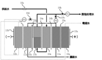
- FIG. 3 is a schematic diagram showing a first example of an electrical concentrator.
- an electrical concentrator 2 has an anode 23a and a cathode 23b. Between the anode 23a and the cathode 23b, there are deionization compartments 20a, 20b, concentration compartments 21a, 21b, electrode compartments 22a, 22b, an anode 23a, a cathode 23b, anion exchange membranes 24a to 24d, and cation exchange membranes 25a, 25b.
- the deionization chamber 20a is disposed on the anode side of the anion exchange membrane 24a, and the deionization chamber 20b is disposed on the cathode side of the anion exchange membrane 24a.
- the deionization chamber 20a is filled with anion exchange resin.
- the deionization chamber 20b has a first region on the upstream side and a second region on the downstream side with respect to the flow direction of the water to be treated flowing through the deionization chamber 20b.
- the first region is filled with a cation exchange resin
- the second region is filled with anion exchange resin.
- the concentration chamber 21a is disposed on the anode side of the deionization chamber 20a.
- the concentration chamber 21a is filled with a cation exchange resin.
- An anion exchange membrane 24b is disposed between the concentration chamber 21a and the deionization chamber 20a.
- the concentration chamber 21a can be called an anion concentration chamber that concentrates anion components.
- the concentration chamber 21b is disposed on the cathode side of the deionization chamber 20b.
- the concentration chamber 21b is filled with an anion exchange resin.
- An ion exchange membrane consisting of an anion exchange membrane 24c and a cation exchange membrane 25b is disposed between the concentration chamber 21b and the deionization chamber 20b.
- the cation exchange membrane 25b is disposed over the entire first and second regions of the deionization chamber 20b.
- the anion exchange membrane 24c is provided on the surface of the cation exchange membrane 25b facing the deionization chamber 20b (the side opposite the concentration chamber 21b).
- the area of the anion exchange membrane 24c is smaller than the area of the cation exchange membrane 25b.
- the anion exchange membrane 24c faces the second region of the deionization chamber 20b.
- the concentration chamber 21b can be called a cation concentration chamber that concentrates cationic components.
- the electrode chamber 22a is disposed on the anode side of the concentration chamber 21a.
- the electrode chamber 22a is filled with a cation exchange resin.
- a cation exchange membrane 25a is disposed between the electrode chamber 22a and the concentration chamber 21a.
- the electrode chamber 22b is disposed on the cathode side of the concentration chamber 21b.
- the electrode chamber 22b is filled with an anion exchange resin.
- An anion exchange membrane 24d is disposed between the electrode chamber 22b and the concentration chamber 21b.
- the supply water (treated water 1b, 1d) first passes through the desalting chamber 20a and then through the desalting chamber 20b.
- the desalting chamber 20b discharges the desalted water.
- a valve 26a is provided in the line for supplying the supply water to the desalting chamber 20a.
- a valve 26b is provided in the line for the desalted water discharged from the desalting chamber 20b, and a flow meter FI1 is provided downstream of this valve 26b.
- the desalinated water discharged from the desalting chamber 20b branches off before the valve 26b, and the branched desalinated water is supplied to the concentration chambers 21a and 21b, respectively.
- a valve 26c is provided on the branch line of the desalinated water, and a flow meter FI2 is provided downstream of this valve 26c. After the flow meter FI2, the line of the desalinated water branches off into two, one line connected to the concentration chamber 21a and the other line connected to the concentration chamber 21b.
- the concentration chambers 21a and 21b each discharge concentrated water.
- the desalinated water discharged from the desalting chamber 20b is further branched off before the branching point to the concentrating chambers 21a and 21b.
- This branched desalinated water first passes through the electrode chamber 22b and then through the electrode chamber 22a.
- the electrode chamber 22a discharges electrode water.
- a valve 26d is provided in the branch line of the desalinated water to the electrode chamber 22b, and a flow meter FI3 is provided downstream of this valve 26d.
- Feed water is supplied to the desalting chambers 20a and 20b, and a portion of the desalted water discharged from the desalting chamber 20 is supplied to the concentration chambers 21a and 21b and the electrode chamber 22b.
- the flow rate of the feed water can be adjusted using valve 26a.
- the flow rate of the desalted water discharged from the desalting chamber 20b can be adjusted using valve 26b.
- the flow rate of the desalted water supplied to the concentration chambers 21a and 21b can be adjusted using valve 26c.
- the flow rate of the desalted water supplied to the electrode chamber 22b can be adjusted using valve 26d.
- a direct current is passed between the anode 23a and the cathode 23b.
- Ions move between the deionization chamber 20a and the concentration chamber 21a via the anion exchange membrane 24b, and the concentration chamber 21a discharges concentrated water with concentrated anionic components.
- Ions move between the deionization chamber 20b and the concentration chamber 21b via the anion exchange membrane 24c and the cation exchange membrane 25b, and the concentration chamber 21b discharges concentrated water with concentrated cationic components.
- the concentrated water discharged from the concentration chamber 21a and the concentrated water discharged from the concentration chamber 21b join together and are supplied to the measuring instrument 3 shown in Figure 1 (or Figure 2).
- FIG. 4 is a schematic diagram showing a second example of an electrical concentrator.
- the electrical concentrator 2 of this example has a deionization compartment 27 and a cation exchange membrane 25c instead of the deionization compartments 20a, 20b, anion exchange membranes 24a, 24c, and cation exchange membrane 25b shown in Fig. 3.
- the configuration other than the deionization compartment 27 and the cation exchange membrane 25c is the same as that shown in Fig. 3.
- the same components as those shown in Fig. 3 are denoted by the same reference numerals, and detailed description thereof will be omitted here.
- the deionization chamber 27 is disposed between the concentration chamber 21a and the concentration chamber 21b.
- An anion exchange membrane 24b is disposed between the deionization chamber 27 and the concentration chamber 21a.
- a cation exchange membrane 25c is disposed between the deionization chamber 27 and the concentration chamber 21b.
- the deionization chamber 27 is filled with a cation exchange resin and an anion exchange resin. Specifically, the deionization chamber 27 is filled with a mixed resin in which a cation exchange resin and an anion exchange resin are mixed in a predetermined ratio.
- the supply water (treated water 1b, 1d) is supplied to the desalting chamber 27.
- the desalting chamber 27 discharges the desalted water.
- the supply water line is provided with a valve 26a.
- the line for the desalted water discharged from the desalting chamber 27 is provided with a valve 26e, and a flow meter FI1 is provided downstream of this valve 26e.
- the desalinated water discharged from the desalting chamber 27 branches off before the valve 26e, and the branched desalinated water is supplied to the concentration chambers 21a and 21b.
- Valve 26f is provided on the branch line of the desalinated water, and a flow meter FI2 is provided downstream of this valve 26f. After the flow meter FI2, the line of the desalinated water branches off into two, one line connected to the concentration chamber 21a and the other line connected to the concentration chamber 21b.
- the concentration chambers 21a and 21b each discharge concentrated water.
- the desalinated water discharged from the desalting chamber 27 is further branched off before the branching point to the concentration chambers 21a and 21b.
- This branched desalinated water first passes through the electrode chamber 22b and then through the electrode chamber 22a.
- the electrode chamber 22a discharges electrode water.
- a valve 26g is provided in the branch line of the desalinated water to the electrode chamber 22b, and a flow meter FI3 is provided downstream of this valve 26g.
- Feed water is supplied to the desalting chamber 27, and a portion of the desalted water discharged from the desalting chamber 27 is supplied to the concentration chambers 21a, 21b and the electrode chamber 22b.
- the flow rate of the feed water can be adjusted using valve 26a.
- the flow rate of the desalted water discharged from the desalting chamber 27 can be adjusted using valve 26e.
- the flow rate of the desalted water supplied to the concentration chambers 21a, 21b can be adjusted using valve 26f.
- the flow rate of the desalted water supplied to the electrode chamber 22b can be adjusted using valve 26g.
- a direct current is passed between the anode 23a and the cathode 23b. Ions move between the deionization chamber 27 and the concentration chamber 21a via the anion exchange membrane 24b, and ions move between the deionization chamber 27 and the concentration chamber 21b via the cation exchange membrane 25c.
- the concentration chamber 21a discharges concentrated water containing concentrated anionic components
- the concentration chamber 21b discharges concentrated water containing concentrated cationic components.
- the concentrated water discharged from the concentration chamber 21a and the concentrated water discharged from the concentration chamber 21b join together and are supplied to the measuring instrument 3 shown in Figure 1 (or Figure 2).
- FIG. 5 is a schematic diagram showing a third example of an electric concentrator.
- the electric concentrator 2 of this example has concentrating chambers 28a and 28b instead of the concentrating chambers 21a and 21b shown in Fig. 4.
- the rest of the configuration is the same as that shown in Fig. 4.
- the same components are given the same reference numerals, and detailed description thereof will be omitted here.
- the concentration chamber 28a is disposed on the anode side of the deionization chamber 27, and the concentration chamber 28b is disposed on the cathode side of the deionization chamber 27.
- An anion exchange membrane 24b is disposed between the concentration chamber 28a and the deionization chamber 27.
- a cation exchange membrane 25c is disposed between the concentration chamber 28b and the deionization chamber 27.
- the concentration chambers 28a and 28b are filled with a mixed resin in which a cation exchange resin and an anion exchange resin are mixed in a predetermined ratio.
- the valves 26a, 26e, 26f, and 26g and the flow meters FI1 to FI3 are disposed in the same manner as in the second example.
- the feed water (treated water 1b, 1d) is supplied to the desalting chamber 27, and a portion of the desalted water discharged from the desalting chamber 27 is supplied to the concentrating chambers 28a, 28b and the electrode chamber 22b.
- the concentrating chambers 28a, 28b each discharge concentrated water.
- a direct current is passed between the anode 23a and the cathode 23b. Ions move between the deionization chamber 27 and the concentration chamber 28a via the anion exchange membrane 24b, and ions move between the deionization chamber 27 and the concentration chamber 28b via the cation exchange membrane 25c.
- the concentration chamber 28a discharges concentrated water containing concentrated anionic components
- the concentration chamber 28b discharges concentrated water containing concentrated cationic components.
- the concentrated water discharged from the concentration chamber 28a and the concentrated water discharged from the concentration chamber 28b join together and are supplied to the measuring instrument 3 shown in Figure 1 (or Figure 2).
- FIG. 6 is a schematic diagram showing a fourth example of an electrical concentrator.
- the electrical concentrator 2 of this example has a dilution compartment 29 instead of the concentration compartment 21b and dilution compartment 27 shown in Fig. 4.
- the rest of the configuration is the same as that shown in Fig. 4.
- the same components are given the same reference numerals, and detailed description thereof will be omitted here.
- the deionization chamber 29 is disposed between the concentration chamber 21a and the electrode chamber 22b.
- Anion exchange membrane 24b is disposed between the deionization chamber 29 and the concentration chamber 21a, and anion exchange membrane 24d is disposed between the deionization chamber 29 and the electrode chamber 22b.
- the deionization chamber 29 is filled with anion exchange resin.
- valves 26a, 26e, 26f, and 26g and flow meters FI1 to FI3 are disposed in the same manner as in the second example.
- the feed water (treated water 1b, 1d) is supplied to the desalting chamber 29, and a portion of the desalted water discharged from the desalting chamber 29 is supplied to the concentrating chamber 21a and the electrode chamber 22b.
- the concentrating chamber 21a discharges concentrated water.
- a direct current is passed between the anode 23a and the cathode 23b. Ions move between the desalting chamber 29 and the concentration chamber 21a via the anion exchange membrane 24b.
- the concentration chamber 21a discharges concentrated water in which the anion components have been concentrated. The concentrated water discharged from the concentration chamber 21a is supplied to the measuring instrument 3 shown in Figure 1 (or Figure 2).
- Electrode 5 7 is a schematic diagram showing a fifth example of an electrical concentrator.
- An electrical concentrator 2 of this example has deionization compartments 30a and 30b, a concentrating compartment 31, an anion exchange membrane 24e, and a cation exchange membrane 25d between an anode 23a and a cathode 23b.
- the deionization chamber 30a is disposed on the anode side of the concentration chamber 31.
- a cation exchange membrane 25d is disposed between the deionization chamber 30a and the concentration chamber 31.
- the deionization chamber 30b is disposed on the cathode side of the concentration chamber 31.
- An anion exchange membrane 24e is disposed between the deionization chamber 30b and the concentration chamber 31.
- the deionization chamber 30a is filled with a cation exchange resin
- the deionization chamber 30b is filled with an anion exchange resin.
- the concentration chamber 31 is filled with a mixed resin in which a cation exchange resin and an anion exchange resin are mixed in a predetermined ratio.
- the deionization chamber 30a is configured to double as an electrode chamber on the anode side
- the deionization chamber 30b is configured to double as an electrode chamber on the cathode side.
- the feed water (treated water 1b, 1d) first passes through the desalting chamber 30b and then through the desalting chamber 30a.
- the desalting chamber 30a discharges the desalted treated water.
- the line for supplying the feed water to the desalting chamber 30a branches, and the branch line is connected to the concentration chamber 31. A portion of the feed water is supplied to the concentration chamber 31 via the branch line.
- the concentration chamber 31 discharges concentrated water.
- a direct current is passed between the anode 23a and the cathode 23b. Ions move between the deionization chamber 30a and the concentration chamber 31 via the cation exchange membrane 25d, and ions move between the deionization chamber 30b and the concentration chamber 31 via the anion exchange membrane 24e.
- the concentration chamber 31 discharges concentrated water in which the anion and cation components have been concentrated. The concentrated water discharged from the concentration chamber 31 is supplied to the measuring instrument 3 shown in Figure 1 (or Figure 2).
- valves and flow meters are provided in the supply line and branch line for the feed water, the discharge line for the concentrated water, and the discharge line for the desalinated water, allowing the flow rates of the feed water, concentrated water, and desalinated water to be adjusted.
- the treated water may be branched and passed through the concentration chamber, but in that case there is a concern that air bubbles generated in the electrode chamber may be mixed in.
- FIG. 8 is a schematic diagram showing a sixth example of an electrical concentrator.
- the electrical concentrator 2 of this example has concentrating chambers 32a and 32b instead of the concentrating chambers 21a and 21b and the anion exchange membrane 24c shown in Fig. 3.
- the configuration other than the concentrating chambers 32a and 32b is the same as that shown in Fig. 3.
- the same components as those shown in Fig. 3 are denoted by the same reference numerals, and detailed description thereof will be omitted here.
- the concentration chamber 32a is disposed on the anode side of the deionization chamber 20a.
- An anion exchange membrane 24b is disposed between the concentration chamber 32a and the deionization chamber 20a.
- the concentration chamber 32a is filled with a mixed resin in which a cation exchange resin and an anion exchange resin are mixed in a predetermined ratio.
- the concentration chamber 32b is disposed on the cathode side of the deionization chamber 20b.
- a cation exchange membrane 25b is disposed between the concentration chamber 32b and the deionization chamber 20b.
- the concentration chamber 32b is filled with a mixed resin in which a cation exchange resin and an anion exchange resin are mixed in a predetermined ratio.
- the valves 26a, 26b, 26c, 26d and the flow meters FI1 to FI3 are disposed in the same manner as in the first example.
- a direct current is passed between the anode 23a and the cathode 23b. Ions move between the deionization chamber 20a and the concentration chamber 32a via the anion exchange membrane 24b, and ions move between the deionization chamber 20b and the concentration chamber 32b via the cation exchange membrane 25b.
- the concentration chamber 32a discharges concentrated water in which the anion components have been concentrated
- the concentration chamber 32b discharges concentrated water in which the cation components have been concentrated.
- the concentrated water discharged from the concentration chamber 32a and the concentrated water discharged from the concentration chamber 32b join together and are supplied to the measuring instrument 3 shown in Figure 1 (or Figure 2).
- the electrical concentrator 2 of this embodiment similarly to the first embodiment, it is possible to adjust the flow rates of the feed water, the desalted water, the concentrated water, and the electrode water.
- a plurality of sections each composed of the deionization compartments 20a, 20b, the concentration compartment 32b, the anion exchange membranes 24a, 24b, and the cation exchange membrane 25b may be provided between the anode 23a and the cathode 23b.
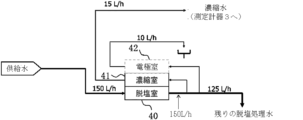
- FIG. 9 is a diagram for explaining an example of a method for calculating the concentration ratio of the concentrating device 2.
- feed water is supplied to the desalting chamber 40.
- the flow rate of the feed water supplied to the desalting chamber 40 is set to 150 L/h.
- the desalting chamber 40 discharges desalted water.
- the flow rate of the desalted water discharged from the desalting chamber 40 is set to 150 L/h.
- a portion of the desalinated water discharged from the deionization compartment 40 is supplied to the concentration compartment 41 and the electrode compartment 42.
- the flow rate of the remaining desalinated water, excluding the amount supplied to the concentration compartment 41 and the electrode compartment 42, is set to 125 L/h.
- Concentrated water is discharged from the concentration chamber 41.
- the flow rate of the concentrated water discharged from the concentration chamber 41 is set to 15 L/h.
- Electrode water is discharged from the electrode chamber 42.
- the flow rate of the electrode water discharged from the electrode chamber 42 is set to 10 L/h.
- the concentration rate of the concentrator 2 can be calculated as follows based on the flow rate of the remaining desalted water, the flow rate of the concentrated water, and the flow rate of the electrode water.
- the concentration (converted value) of the specific component in the treated water 1b can be calculated by dividing the measured value of the measuring instrument 3 by the concentration ratio.
- the concentration chamber 41 also serves as the electrode chamber 42 due to the structure of the concentrating device 2. In that case, the flow rate of the electrode water is omitted when calculating the concentration ratio.
- Fig. 10 is a diagram for explaining another example of a method for calculating the concentration ratio of the concentrating device 2.
- feed water is supplied to the desalting compartment 40, the concentrating compartment 41, and the electrode compartment 42.
- the flow rate of the feed water supplied to the desalting compartment 40 is set to 125 L/h.
- the desalting compartment 40 discharges desalted water.
- the flow rate of the desalted water discharged from the desalting compartment 40 is set to 125 L/h.
- Concentrated water is discharged from the concentration chamber 41.
- the flow rate of the concentrated water discharged from the concentration chamber 41 is set to 15 L/h.
- Electrode water is discharged from the electrode chamber 42.
- the flow rate of the electrode water discharged from the electrode chamber 42 is set to 10 L/h.
- the concentration rate of the concentrator 2 can be calculated as follows.
- the concentration (converted value) of the specific component in the treated water 1b can be calculated by dividing the measured value of the measuring instrument 3 by the concentration factor.
- the concentration chamber 41 may also serve as the electrode chamber 42. In this case, the flow rate of the electrode water is omitted when calculating the concentration factor.
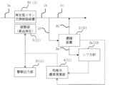
- FIG. 11 is a block diagram showing a water treatment system of the first embodiment.
- the water treatment system of the first embodiment is an application of the water treatment system of the second embodiment shown in FIG. 2.
- the water treatment device 1 is configured with a two-stage RO consisting of reverse osmosis (RO) membrane separation devices 50 and 51.
- the feed water (water to be treated) 1a was supplied to the first-stage RO membrane separation device 50, and the permeate of the RO membrane separation device 50 was supplied to the second-stage RO membrane separation device 51.
- a concentrator 2 was arranged in the permeate line of the second-stage RO membrane separation device 51. As the concentrator 2, an electric concentrator shown in FIG. 3 was used, and the concentration ratio was set to about 11 times.
- an online silica meter 3a (high sensitivity silica monitor SLIA-300 manufactured by Horiba Advanced Techno Co., Ltd.) was used.
- the desalted treated water 2b discharged from the electric concentrator 2 was sent to the subsequent stage.
- the operation and management of the water treatment system of this first embodiment was carried out.
- the concentration of silica components contained in the concentrated water 2a discharged from the electric concentrator 2 was measured using a silica meter 3a. As the measurement results showed that the silica concentration tended to be high, the pH of the second stage RO inlet was adjusted to the alkaline side to improve the silica removal performance of the RO membrane.
- Figure 12 is a diagram to explain the change in silica concentration before and after adjustment.
- Figure 12(a) shows the silica measurement value, concentration ratio, conversion value, and pH value at the second RO inlet before and after adjustment.
- Figure 12(b) shows the change in the silica conversion value and the change in the pH value at the second RO inlet before and after adjustment.
- the broken line indicated by black squares shows the change in the silica conversion value
- the broken line indicated by white circles shows the change in the pH value at the second RO inlet.
- the online silica meter 3a by using the online silica meter 3a, it was possible to grasp the change in the silica concentration of the permeate discharged from the second-stage RO membrane separation device 51, and by adjusting the operation without overlooking small fluctuations, it was possible to stabilize the silica concentration at 3 ⁇ g/L or less.
- the conductivity (resistivity) of the RO permeate was 1.0 ⁇ S/cm (1.0 M ⁇ cm) before the pH adjustment and 4.0 ⁇ S/cm (0.25 M ⁇ cm) after the adjustment, which was a value of 5 ⁇ S/cm or less. This shows that the treated water (RO permeate) that satisfies the required water quality for washing water can be stably maintained.
- FIG. 13 is a block diagram showing a water treatment system of the second embodiment.
- the water treatment system of the second embodiment is an application of the water treatment system of the first embodiment shown in FIG. 1.
- the water treatment device 1 is configured with a chemical regenerating ion exchange resin device 60.
- the chemical regenerating ion exchange resin device 60 is a regenerating ion exchange resin device that regenerates ion exchange resin using chemicals.
- the feed water (water to be treated) 1a was supplied to the chemical regenerating ion exchange resin device 60.
- a concentrator 2 was placed on a line branched from the treated water line of the chemical regenerating ion exchange resin device 60. As the concentrator 2, an electric concentrator shown in FIG. 3 was used, and the concentration ratio was set to 8 times.
- an online silica meter 3a (high sensitivity silica monitor SLIA-300 manufactured by Horiba Advanced Techno Co., Ltd.) was used.
- the desalted treated water 2b discharged from the electric concentrator 2 was sent to the subsequent stage together with the treated water discharged from the chemical regenerating ion exchange resin device 60.
- Figure 14 is a diagram explaining the change in silica concentration before and after chemical regeneration. As can be seen from Figure 14, immediately after chemical regeneration was performed, the silica concentration began to decline, and then reached an inflection point and began to rise. This upward trend in silica concentration was captured and the timing of chemical regeneration was adjusted. This enabled optimal operation.
- the interval between chemical regenerations is set with a safety margin.
- there is no need to ensure such a safety margin so the size of the equipment can be significantly slimmed down.
- by identifying trends in performance decline or increase at an early stage it is possible to approach a more optimal regeneration frequency.
- FIG. 15 is a block diagram showing a water treatment system of the third embodiment.
- the water treatment system of the third embodiment is an application of the water treatment system of the first embodiment shown in FIG. 1.
- the water treatment device 1 is composed of a non-regenerative ion exchange resin device (CP) 61.
- the feed water (water to be treated) 1a was supplied to the non-regenerative ion exchange resin device 61.
- the concentrator 2 was arranged on a line branched from the treated water line of the non-regenerative ion exchange resin device 61. As the concentrator 2, the electric concentrator shown in FIG. 3 was used, and the concentration ratio was set to about 7 times.
- an online silica meter 3a (high sensitivity silica monitor SLIA-300 manufactured by Horiba Advanced Techno Co., Ltd.) was used.
- the desalted treated water 2b discharged from the electric concentrator 2 was sent to the subsequent stage together with the treated water discharged from the non-regenerative ion exchange resin device 61.
- Figure 16 shows the change in silica concentration.
- silica components were leaking from the non-regenerative ion exchange resin device 61 at a stable concentration, and it was determined that it was time to replace the resin.
- concentration of the concentrated water 2a from the electric concentrator 2 it was possible to confirm low-concentration silica components that could not normally be measured on-site using online instruments.
- Example 4 Fig. 17 is a block diagram showing a water treatment system of the fourth embodiment.
- the water treatment system of the fourth embodiment is an application of the water treatment system of the first embodiment shown in Fig. 1.
- the water treatment device 1 is composed of an electrical regenerative deionized water production device (EDI device) 62.
- the EDI device 62 is configured so that its treatment performance improves when the value of the current supplied thereto is increased.
- the feed water (water to be treated) 1a was supplied to the EDI device 62.
- the concentrator 2 was placed on a line branching off from the treated water line of the EDI device 62.
- the electric concentrator shown in Figure 4 was used as the concentrator 2, and the concentration ratio was set to approximately 3 times.
- An online boron meter 3b (Sievers UPW Boron Analyzer, manufactured by Suez) was used as the measuring instrument 3.
- the desalted treated water 2b discharged from the electric concentrator 2 was sent to the subsequent stage together with the treated water discharged from the EDI device 62.
- Fig. 18 is a diagram for explaining the change in boron concentration.
- the boron concentration of the treated water of the EDI device 62 fluctuated. Since the boron concentration was trending higher, the current value supplied to the EDI device 62 was increased. Specifically, the current value was increased from 4.0 A to 5.0 A. This adjustment reduced the fluctuation range of the boron concentration, and it was confirmed that the treatment performance of the EDI device 62 was improved.
- Example 5 Fig. 19 is a block diagram showing a water treatment system of the fifth embodiment.
- the water treatment system of the fifth embodiment is an application of the water treatment system of the first embodiment shown in Fig. 1.
- the water treatment device 1 is configured with an EDI device 63.
- the EDI device 63 is configured such that the treatment performance is improved when the temperature of the supply water (water to be treated) 1a is lowered.
- the feed water 1a was supplied to the EDI device 63.
- the concentrator 2 was placed on a line branching off from the treated water line of the EDI device 63.
- the electric concentrator shown in Figure 4 was used as the concentrator 2, and the concentration ratio was set to approximately 3 times.
- An online boron meter 3b (Sievers UPW Boron Analyzer, manufactured by Suez) was used as the measuring instrument 3.
- the desalted treated water 2b discharged from the electric concentrator 2 was sent to the subsequent stage together with the treated water discharged from the EDI device 63.
- Figure 20 is a diagram for explaining the change in boron concentration.
- the boron concentration of the treated water from the EDI device 63 remained at a high value.
- the temperature of the supply water 1a was lowered from 25°C to 20°C to improve the treatment performance of the EDI device 63.
- the resistivity of the treated water from the EDI device 63 before and after the water temperature adjustment was stable between 18.0 and 18.2 M ⁇ cm. It was confirmed that because the water temperature can be adjusted while monitoring the boron concentration, it is possible to respond appropriately when the amount of boron inflow from the pretreatment device installed upstream of the EDI device 63 increases.
- Example 6 Fig. 21 is a block diagram showing a water treatment system according to a sixth embodiment.
- the water treatment system according to the sixth embodiment is an application of the water treatment system according to the first embodiment shown in Fig. 1.
- the water treatment device 1 is configured with the EDI device 62 used in the fourth embodiment.
- the feed water (water to be treated) 1a was supplied to the EDI device 62.
- the concentrator 2 was placed on a line branching off from the treated water line of the EDI device 62.
- the electric concentrator shown in Figure 4 was used as the concentrator 2, and the concentration ratio was set to approximately 20 times.
- An online TOC meter 3c (Sievers m9e, manufactured by Suez) was used as the measuring instrument 3.
- the desalted treated water 2b discharged from the electric concentrator 2 was sent to the subsequent stage together with the treated water discharged from the EDI device 62.
- FIG. 22 is a diagram for explaining the change in IC concentration. As can be seen from FIG. 22, the IC concentration of the treated water from the EDI device 62 is stable at a low value, but it has been confirmed that it is showing a downward trend. In this sixth embodiment, the IC concentration was monitored without adjusting the current.
- an electric concentrator is used as the concentrator 2 in the water treatment system of the first or second embodiment, but an RO membrane separation device may be used instead.
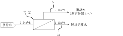
- Fig. 23 is a diagram for explaining an example of a method for calculating the concentration ratio of an RO membrane separation device.
- feed water is supplied to an RO membrane separation device 70.
- the flow rate of the feed water supplied to the RO membrane separation device 70 is 1.24 m3 /h.
- the RO membrane separation device 70 discharges concentrated water 2a and desalted water (permeate) 2b.
- the flow rate of the concentrated water 2a discharged from the RO membrane separation device 70 is 0.12 m3 /h.
- the flow rate of the desalted water 2b discharged from the RO membrane separation device 70 is 1.12 m3 /h.
- the concentration ratio of the RO membrane separation device 70 can be calculated as follows. By dividing the measured value of the measuring instrument 3 by the concentration factor, it is possible to calculate the concentration (converted value) of the specific component in the treated water 1b.
- An 8-inch element of XLE-440 (manufactured by DuPont) was used as the RO membrane.
- the flow rates of the feed water, concentrated water 2a, and desalted water 2b were set under the conditions described above, and the RO membrane separation device 70 was operated so that the concentration ratio was 10.3 times.
- the feed water had a resistivity of 0.1 M ⁇ cm, a sodium concentration of 1.1 ppm, and a silica concentration of 1.6 ppm.
- Figure 24 shows the measurement results for sodium and silica.
- the measured Na concentration in the concentrated water was 7.2 ppm, and the equivalent concentration value obtained by dividing this measurement by the concentration rate was 0.7 ppm. It was found that this equivalent concentration value of 0.7 ppm was significantly different from the actual concentration (1.1 ppm).
- the sodium concentration of the desalted water (RO permeate) was measured, it was found to be 0.4 ppm, and the desalination rate was found to be approximately 64%.
- the measured silica concentration of the concentrated water was 15.2 ppm, and the converted concentration value obtained by dividing the measured silica concentration by the concentration factor was 1.5 ppm. It was found that this converted concentration value of 1.5 ppm was almost the same as the actual concentration (1.6 ppm).
- the silica concentration of the desalted water (RO permeate) was measured, it was found to be 0.1 ppm, and the desalting rate was about 94%.
- a component with a low salt rejection rate e.g., sodium
- an electric concentrator has a rejection rate of 90% or more for both sodium and silica. Therefore, when an electric concentrator is used as the concentrator 2, it is possible to accurately determine the concentration of components such as sodium in the treated water discharged from the water treatment device 1, which is difficult to accurately determine using an RO membrane separation device. Therefore, compared to an RO membrane separation device, an electric concentrator has the effect of relaxing the restrictions on the components to be concentrated. Note that there are many different types of RO membranes, and some have a high sodium removal rate depending on the membrane selected, so it may be possible to respond by selecting a membrane with high removal performance for the component to be measured.
- Figure 25 shows an example of a measurement using a silica meter 3a without a concentrator 2.
- Figure 25 shows the change in the measured silica concentration before and after chemical regeneration.
- the silica meter 3a was used to measure the silica concentration of treated water 1d, which is part of treated water 1b discharged from a chemical regeneration type ion exchange resin device 60.
- the silica meter 3a was unable to measure silica concentrations below a lower limit of about 200 ppt.
- Figure 26 shows an example of measurement using a silica meter 3a when a concentrator 2 is included.
- Figure 26 shows the change in silica concentration (converted value) before and after chemical regeneration.
- the silica meter 3a was used to measure the silica concentration of concentrated water 2a obtained by concentrating treated water 1d, which is a part of treated water 1b discharged from a chemical regeneration-type ion exchange resin device 60.
- the silica concentration of concentrated water 2a was a value of 200 ppt or more, and could be measured using the silica meter 3a. From this result, it was confirmed that by using the concentrator 2, it is possible to measure using the silica meter 3a even when the silica concentration is 200 ppt or less, and the usefulness of the concentrator 2 was confirmed.
- Patent Document 3 describes an underwater ion monitor that includes an electrodialysis device (concentrating device) that concentrates ions in water and an electrical conductivity meter (measuring instrument) that measures the electrical conductivity of the ion concentrated water concentrated by the electrodialysis device.
- the water quality measuring devices described herein, including the underwater ion monitor described in Patent Document 1 have the following problems.
- the flow rate required for measuring the concentration of the measuring instrument is fixed. Therefore, for example, if the concentrating device performs concentration of 10 times or more, the treated water needs to be passed through the concentrating device at a flow rate of 10 times or more the flow rate required for the measuring instrument.
- An object of the present embodiment is to provide a water quality measuring device, a water treatment system, and a water quality measuring method that enable the concentrating device to be made smaller.
- FIG. 27 is a block diagram showing the configuration of a water treatment system according to the third embodiment of the present invention.
- the water treatment system of this embodiment includes a water treatment device 1, a water quality measuring device 10, and a monitoring unit 11.
- the water treatment device 1 treats the water to be treated 1a to produce treated water 1b.
- the treated water 1b is, for example, pure water (or ultrapure water), and its specific resistance is, for example, 0.10 M ⁇ cm or more (conductivity 10 ⁇ S/cm or less).
- the treated water 1b produced by the water treatment device 1 is branched into two, one of which is supplied to a use point or a downstream treatment device as treated water 1c, and the other is supplied to the water quality measuring device 10 as treated water 1d.
- the water treatment device 1 includes, for example, at least one of a reverse osmosis (RO) membrane separation device, a regenerative ion exchange resin device, a non-regenerative ion exchange resin device, and an electric regenerative deionized water production device (EDI).
- RO reverse osmosis
- EDI electric regenerative deionized water production device
- the water treatment device 1 may include other devices for water treatment.
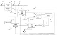
- the water quality measuring device 10 includes a concentrator 2, a measuring instrument 3, a storage section 7, a timer 8, a sensor 9, a control section 12, and a water supply pump 13.
- the concentrator 2 is configured to pass treated water 1d, which is a part of treated water 1b produced by the water treatment device 1.
- the concentrator 2 concentrates a specific component (a component to be concentrated) contained in the treated water 1d.
- the concentrator 2 supplies a signal indicating the concentration ratio to the monitoring section 11.
- the concentrator 2 is, for example, a desalination device that produces at least concentrated water 2a and desalted treated water 2b.
- the removal rate (densification rate) of the specific component is 90% or more, preferably 95% or more, and more preferably 99% or more.
- the concentration rate of the concentrated water 2a relative to the treated water 1d is 3 times or more, preferably 10 times or more, and more preferably 20 times or more. In this embodiment, the removal rate (densification rate) is 90% or more, and the concentration rate is in the range of 3 to 20 times.
- the concentrated water 2a is supplied to the storage section 7.
- the desalted water 2b is combined with the treated water 1c and supplied to the point of use. It is also possible to supply all of the treated water 1b produced by the water treatment device 1 to the concentrator 2 as treated water 1d.
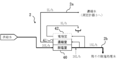
- Fig. 28 is a schematic diagram showing one configuration example of the concentrator 2.
- the concentrator 2 shown in Fig. 28 has a deionization compartment 40, a concentration compartment 41, and an electrode compartment 42.
- Feed water (treated water 1d) is supplied to the deionization compartment 40.
- the flow rate of the feed water supplied to the deionization compartment 40 is set to 20 L/h.
- the deionization compartment 40 discharges desalted water.
- the flow rate of the desalted water discharged from the deionization compartment 40 is set to 20 L/h.
- a portion of the desalinated water discharged from the desalting chamber 40 is supplied to the concentrating chamber 41 and the electrode chamber 42.
- the flow rate of the remaining desalinated water, excluding the amount supplied to the concentrating chamber 41 and the electrode chamber 42, is set to 15 L/h.
- This remaining desalinated water corresponds to the desalinated water 2b shown in FIG.
- the concentration chamber 41 discharges concentrated water 2a.
- the flow rate of concentrated water 2a discharged from the concentration chamber 41 is set to 2 L/h.
- the electrode chamber 42 discharges electrode water.
- the flow rate of electrode water discharged from the electrode chamber 42 is set to 3 L/h.
- the concentration rate of the concentrator 2 can be calculated as follows based on the flow rate of the remaining desalted water 2b, the flow rate of the concentrated water 2a, and the flow rate of the electrode water.
- the concentration (converted value) of the specific component in the treated water 1b can be calculated by dividing the measured value of the measuring instrument 3 by the concentration ratio.
- the concentration chamber 41 also serves as the electrode chamber 42 due to the structure of the concentrating device 2. In that case, the flow rate of the electrode water is omitted when calculating the concentration ratio.
- Fig. 29 is a schematic diagram showing another configuration example of the concentrating device 2.
- the concentrating device 2 shown in Fig. 29 is composed of an RO membrane separation device 70.
- Feed water (treated water 1d) is supplied to the RO membrane separation device 70.
- the flow rate of the feed water supplied to the RO membrane separation device 70 is 1.24 m3 /h.
- the RO membrane separation device 70 discharges concentrated water 2a and desalted water (permeate) 2b.
- the flow rate of the concentrated water 2a discharged from the RO membrane separation device 70 is 0.12 m3 /h.
- the flow rate of the desalted water 2b discharged from the RO membrane separation device 70 is 1.12 m3 /h.
- the concentration ratio of the RO membrane separation device 70 can be calculated as follows. By dividing the measured value of the measuring instrument 3 by the concentration factor, it is possible to calculate the concentration (converted value) of the specific component in the treated water 1b.
- the storage unit 7 is configured to store the concentrated water 2a from the concentrating device 2 and supply the stored concentrated water 2a to the measuring instrument 3.
- a water supply pump 13 is provided in the piping connecting the storage unit 7 and the measuring instrument 3, and this water supply pump 13 supplies the concentrated water 2a stored in the storage unit 7 to the measuring instrument 3.
- the storage unit 7 can be configured as a tank or a water tank, but is not limited to this.
- the storage unit 7 may have any structure as long as it is capable of storing the concentrated water 2a.
- the measuring instrument 3 measures the concentration of a specific component contained in the concentrated water 2a supplied from the storage unit 7.
- the measuring instrument 3 supplies a signal indicating the measured value to the monitoring unit 11.
- the measuring instrument 3 is, for example, an instrument that measures the concentration of any of the following components: silica, boron, metal ions (sodium, aluminum, calcium, magnesium, etc.), carbonate, IC (inorganic carbon), and TOC (total organic carbon). Note that these instruments are only examples, and instruments that measure the concentration of other components may also be used.
- the concentrated water that passes through the measuring instrument 3 is basically discarded, but from the standpoint of utilization efficiency, it may be returned to the upstream or downstream of the water treatment device 1, or may be used in another system.
- the control unit 12 controls the operation of the water pump 13.
- the control unit 12 operates the water pump 13 during the measurement period of the measuring instrument 3.
- Either the timer 8 or the sensor 9 can be used to control the water pump 13.
- the timer 8 measures the elapsed time.
- the control unit 12 operates the water pump 13 at predetermined time intervals based on the time measured by the timer 8.
- the predetermined time may be, for example, the time required to store in the storage unit 7 the amount required for the concentration measurement by the measuring instrument 3.
- the control unit 12 controls the operation of the water pump 13 according to the water level detected by the sensor 9. Specifically, the control unit 12 operates the water pump 13 when the water level detected by the sensor 9 reaches a first level, and stops the water pump when the water level detected by the sensor 9 reaches a second level lower than the first level.
- the storage amount between the first level and the second level may be, for example, a storage amount corresponding to the amount required for concentration measurement by the measuring instrument 3.
- the monitoring unit 11 monitors the water quality of the treated water 1b based on the measured value of the measuring instrument 3.
- the monitoring unit 11 has a treated water concentration calculation unit 4, an adjustment unit 5, and an alarm output unit 6.
- the treated water concentration calculation unit 4 calculates the concentration value (conversion value) of a specific component in the treated water 1b by dividing the measured value of the measuring instrument 3 by the concentration ratio of the concentrating device 2.
- the concentration value (conversion value) is supplied to the adjustment unit 5 and the alarm output unit 6.
- the concentration ratio may be a preset value, or may be a value constantly calculated from the values of each flow meter installed in the concentrating device 2.
- the adjustment unit 5 adjusts the treatment state of the water treatment device 1 for a specific component based on the concentration value (conversion value) of the specific component in the treated water 1b.
- the adjustment unit 5 is configured to be able to perform at least one of the following adjustments, for example: flow rate adjustment, chemical regeneration, ion exchange resin replacement, current adjustment, water temperature adjustment, and pH adjustment. These adjustments will be described in detail in the examples below. Note that these adjustments may also be performed by an administrator.
- the alarm output unit 6 outputs an alarm based on the concentration value (converted value) of a specific component in the treated water 1b. For example, the alarm output unit 6 outputs an alarm when the concentration value (converted value) of a specific component in the treated water 1b exceeds a threshold value or when a trend indicating a decrease in the treatment performance for the specific component is detected.
- the alarm output unit 6 may include a display device that displays a message indicating the alarm, or a speaker that outputs an alarm sound. In this case, the administrator can carry out the necessary work for performance recovery processing in response to the alarm (message or alarm sound) from the alarm output unit 6.
- the water quality measuring device 10 is configured to increase the flow rate of concentrated water supplied from the storage section 7 to the measuring device 3 during the measurement period of the measuring device 3, compared to the flow rate of concentrated water supplied from the concentrating device 2 to the storage section 7. This makes it possible to reduce the size of the concentrating device 2. Below, this effect will be specifically explained in comparison with the water quality measuring device of the water treatment system of the comparative example.
- FIG. 30 is a block diagram showing the configuration of a water treatment system of a comparative example.
- the water treatment system shown in FIG. 30 is the same as the water treatment system shown in FIG. 27, except that it has a water quality measuring device 10A instead of the water quality measuring device 10.
- the water quality measuring device 10A has a concentrating device 2A and a measuring instrument 3A, but does not have a storage section 7, timer 8, sensor 9, control section 12, or water pump 13.
- the concentrating device 2A and measuring instrument 3A have the same configuration as the concentrating device 2 and measuring instrument 3 shown in FIG. 27.
- the concentration ratio of the concentrating device 2A is 10 times, and the concentration is measured every 30 minutes by the measuring instrument 3A.
- the flow rate required for the concentration measurement by the measuring instrument 3A is 12 L/h, and it is necessary to pass the treated water 1d through the concentrating device 2A at a flow rate of 120 L/h, which is 10 times the flow rate required for the concentration measurement by the measuring instrument 3A.
- the larger the flow rate of the treated water 1d passed through the larger the size of the concentrating device 2A will be, so in the water quality measuring device 10A of the comparative example, the concentrating device 2A tends to be large.
- the concentrated water 2a discharged from the concentrator 2 is stored in the storage section 7, and during the measurement period of the measuring instrument 3, the pump 13 is operated to supply the concentrated water 2a stored in the storage section 7 to the measuring instrument 3.
- the specifications of the measuring instrument 3 are the same as those of the measuring instrument 3A.
- the concentration ratio of the concentrator 2 is also set to 10 times, and the measuring instrument 3 measures the concentration every 30 minutes.
- the flow rate A supplied from the concentrator 2 to the storage section 7 is set to 2 L/h, and the flow rate required for the measuring instrument 3 to measure the concentration is set to 12 L/h.
- the water flow rate of the concentrator 2 (20 L/h) is significantly lower than the water flow rate of the comparative example concentrator 2A (120 L/h). It is possible to reduce the size of the flow rate of the concentrator 2 to one-sixth that of the concentrator 2A.
- An electrical regenerative deionized water production apparatus can be used as the concentrator 2 (2A).
- EDI apparatus the water quality is not stable immediately after the start of operation, and it takes time for the water quality to stabilize after the start of operation. For this reason, when an EDI apparatus is used as the concentrator 2, 2A, the EDI apparatus needs to be operated all the time, not just during the measurement period of the measuring instrument 3. In the following, it is assumed that both the concentrator 2, 2A are EDI apparatuses.
- the concentrating device 2A needs to be operated continuously. Therefore, in the comparative water quality measuring device 10A, concentrated water is constantly discharged from the concentrating device 2A at a flow rate of 12 L/h. 27, concentrated water is constantly discharged from the concentrator 2 at a flow rate of 2 L/h. In this case, the amount of concentrated water discharged from the concentrator 2 can be reduced to one-sixth of the amount of concentrated water discharged from the concentrator 2A.
- the concentration of the specific component in the pure water level treated water 1b is lower than the lower limit of the concentration that can be measured by the measuring instrument 3, it is difficult to accurately measure the concentration of the specific component in the treated water 1b using the measuring instrument 3.
- the measuring instrument 3 measures the concentration of the specific component in the concentrated water 2a obtained by concentrating the treated water 1d, which is a part of the treated water 1b.
- the concentration of the specific component in the concentrated water 2a is higher than the lower limit of the concentration that can be measured by the measuring instrument 3. Therefore, the measuring instrument 3 can be used to accurately measure the concentration of the specific component in the concentrated water 2a.
- the measured value of the concentrated water 2a can be converted into the concentration value of the specific component in the treated water 1b by dividing it by the concentration ratio of the concentrating device 2. This makes it possible to obtain the concentration (converted value) of the specific component in the pure water level treated water 1b.
- Figure 31 shows the change in silica concentration at the outlet when an ion exchange resin device is used as the water treatment device 1.
- an ion exchange resin device is used as the water treatment device 1.
- Figure 31 by measuring the concentration of concentrated water 2a from the concentrator 2, it was possible to confirm a low concentration (51 ppt in this case) of silica components that could not normally be measured on-site using an online meter.
- Fig. 32 is a block diagram showing the configuration of a water treatment system according to a fourth embodiment of the present invention.
- the water treatment system of this embodiment differs from the water treatment system of the third embodiment in that a switching valve 14 is provided in a water quality measuring device 10 to circulate concentrated water.
- a switching valve 14 is provided in a water quality measuring device 10 to circulate concentrated water.
- Fig. 32 the same components as those in the water treatment system of the third embodiment are given the same reference numerals, and detailed descriptions thereof will be omitted.
- the outlet line 15a of the water pump 13 branches into a supply line 15b to the measuring instrument 3 and a circulation line 15c to the storage section 7, and a switching valve 14 is provided at this branch.
- the switching valve 14 connects the outlet line 15a to either the supply line 15b or the circulation line 15c.
- the control unit 12 controls the operation of the switching valve 14. With the water supply pump 13 running, the control unit 12 controls the switching valve 14 to connect the outlet line 15a and the supply line 15b during the measurement period of the measuring instrument 3, and controls the switching valve 14 to connect the outlet line 15a and the circulation line 15c outside the measurement period.
- the switching valve 14 can be controlled using either the timer 8 or the sensor 9. Specifically, the control unit 12 controls the switching valve 14 to switch between a first state in which the outlet line 15a and the supply line 15b are connected and a second state in which the outlet line 15a and the circulation line 15c are connected at predetermined time intervals based on the time measured by the timer 8.
- the control unit 12 also controls the switching valve 14 to switch between a first state and a second state depending on the water level detected by the sensor. Specifically, the control unit 12 sets the switching valve 14 to the first state when the water level detected by the sensor 9 reaches the first level, and sets the switching valve 14 to the second state when the water level detected by the sensor 9 reaches a second level lower than the first level.
- the storage amount between the first level and the second level may be, for example, a storage amount corresponding to the amount required for concentration measurement by the measuring instrument 3.
- the concentrated water discharged from the water pump 13 is supplied to the measuring instrument 3, but outside the measurement period, the concentrated water discharged from the water pump 13 is returned to the storage unit 7 via the circulation line 15c.
- the storage unit 7 is a tank or a water tank, the concentration of the concentrated water stored in the storage unit 7 may differ between the upper and lower sides.
- the water quality of the concentrated water stored in the storage unit 7 can be stabilized. As a result, the measurement accuracy of the measuring instrument 3 can be improved.
- the configurations shown in the drawings are merely examples, and can be appropriately modified as necessary.
- the water pump 13 is provided between the storage unit 7 and the measuring instrument 3, but is not limited thereto.
- the water pump 13 may be provided inside the measuring instrument 3.
- a measuring instrument having a pump function may be used as the measuring instrument 3.
- the concentrated water is supplied from the storage unit 7 to the measuring instrument 3 using the water pump 13, but this is not limiting. Any structure may be used as long as it is possible to supply the concentrated water stored in the storage unit 7 to the measuring instrument 3. For example, a structure may be applied that uses gravity to supply concentrated water from the storage unit 7 to the measuring instrument 3. In this case, a valve may be used to control the flow rate and on/off of the concentrated water.
Landscapes
- Engineering & Computer Science (AREA)
- Chemical & Material Sciences (AREA)
- Water Supply & Treatment (AREA)
- Chemical Kinetics & Catalysis (AREA)
- Life Sciences & Earth Sciences (AREA)
- Hydrology & Water Resources (AREA)
- Environmental & Geological Engineering (AREA)
- Organic Chemistry (AREA)
- Health & Medical Sciences (AREA)
- Urology & Nephrology (AREA)
- Nanotechnology (AREA)
- Electrochemistry (AREA)
- General Chemical & Material Sciences (AREA)
- Molecular Biology (AREA)
- Analytical Chemistry (AREA)
- Separation Using Semi-Permeable Membranes (AREA)
- Water Treatment By Electricity Or Magnetism (AREA)
- Investigating Or Analyzing Materials By The Use Of Electric Means (AREA)
Priority Applications (2)
| Application Number | Priority Date | Filing Date | Title |
|---|---|---|---|
| JP2025561734A JPWO2025121015A1 (https=) | 2023-12-06 | 2024-10-22 | |
| JP2026002475A JP2026042975A (ja) | 2023-12-06 | 2026-01-09 | 水処理システム、水質測定装置、および水質測定方法 |
Applications Claiming Priority (4)
| Application Number | Priority Date | Filing Date | Title |
|---|---|---|---|
| JP2023206112 | 2023-12-06 | ||
| JP2023-206112 | 2023-12-06 | ||
| JP2024010924 | 2024-01-29 | ||
| JP2024-010924 | 2024-01-29 |
Publications (1)
| Publication Number | Publication Date |
|---|---|
| WO2025121015A1 true WO2025121015A1 (ja) | 2025-06-12 |
Family
ID=95980803
Family Applications (1)
| Application Number | Title | Priority Date | Filing Date |
|---|---|---|---|
| PCT/JP2024/037517 Pending WO2025121015A1 (ja) | 2023-12-06 | 2024-10-22 | 水処理システム、水質測定装置、および水質測定方法 |
Country Status (3)
| Country | Link |
|---|---|
| JP (2) | JPWO2025121015A1 (https=) |
| TW (1) | TW202540004A (https=) |
| WO (1) | WO2025121015A1 (https=) |
Citations (4)
| Publication number | Priority date | Publication date | Assignee | Title |
|---|---|---|---|---|
| JP2004077299A (ja) * | 2002-08-19 | 2004-03-11 | Kurita Water Ind Ltd | 検水の濃縮装置及び濃縮方法 |
| JP2009092564A (ja) * | 2007-10-10 | 2009-04-30 | Kurita Water Ind Ltd | 検水の濃縮方法及び濃縮装置 |
| JP2009156692A (ja) * | 2007-12-26 | 2009-07-16 | Kurita Water Ind Ltd | 検水の連続モニタリング方法および装置 |
| JP2021084045A (ja) * | 2019-11-25 | 2021-06-03 | オルガノ株式会社 | 超純水製造装置とその水質管理方法 |
Family Cites Families (1)
| Publication number | Priority date | Publication date | Assignee | Title |
|---|---|---|---|---|
| JPH08166377A (ja) * | 1994-12-13 | 1996-06-25 | Kurita Water Ind Ltd | 水質モニター及び水質モニタリング方法 |
-
2024
- 2024-10-22 JP JP2025561734A patent/JPWO2025121015A1/ja active Pending
- 2024-10-22 WO PCT/JP2024/037517 patent/WO2025121015A1/ja active Pending
- 2024-11-29 TW TW113146160A patent/TW202540004A/zh unknown
-
2026
- 2026-01-09 JP JP2026002475A patent/JP2026042975A/ja active Pending
Patent Citations (4)
| Publication number | Priority date | Publication date | Assignee | Title |
|---|---|---|---|---|
| JP2004077299A (ja) * | 2002-08-19 | 2004-03-11 | Kurita Water Ind Ltd | 検水の濃縮装置及び濃縮方法 |
| JP2009092564A (ja) * | 2007-10-10 | 2009-04-30 | Kurita Water Ind Ltd | 検水の濃縮方法及び濃縮装置 |
| JP2009156692A (ja) * | 2007-12-26 | 2009-07-16 | Kurita Water Ind Ltd | 検水の連続モニタリング方法および装置 |
| JP2021084045A (ja) * | 2019-11-25 | 2021-06-03 | オルガノ株式会社 | 超純水製造装置とその水質管理方法 |
Also Published As
| Publication number | Publication date |
|---|---|
| JP2026042975A (ja) | 2026-03-11 |
| JPWO2025121015A1 (https=) | 2025-06-12 |
| TW202540004A (zh) | 2025-10-16 |
Similar Documents
| Publication | Publication Date | Title |
|---|---|---|
| KR102602540B1 (ko) | 초순수 제조 장치 및 초순수 제조 장치의 운전 방법 | |
| JP4973853B2 (ja) | 純水製造システム | |
| CN101468836A (zh) | 电渗析装置和方法 | |
| JP6070345B2 (ja) | 逆浸透膜分離装置 | |
| KR20130085220A (ko) | 역삼투 막의 막오염 진단 기능을 가지는 해수담수화장치 | |
| JP2020171892A (ja) | 中空糸膜損傷検出装置及び超純水製造装置並びに中空糸膜損傷検出方法 | |
| JP4119871B2 (ja) | 水精製水手段が装備されたシステム | |
| US20080302651A1 (en) | Performance Maintaining Method For Electrolyzed Functional Water Generating Apparatus | |
| WO2023149414A1 (ja) | 超純水製造装置、および超純水製造装置の運転管理方法 | |
| US20220162108A1 (en) | Apparatus and method for providing purified water | |
| KR101954141B1 (ko) | 전기 흡착모듈의 세정 제어장치 | |
| US20220194816A1 (en) | Apparatus and method for providing purified water | |
| WO2025121015A1 (ja) | 水処理システム、水質測定装置、および水質測定方法 | |
| JP6158681B2 (ja) | 脱イオン水製造システム及びその運転方法 | |
| JP2014004550A (ja) | 水処理設備の制御方法及び制御プログラム並びに水処理システム | |
| JP2011045802A (ja) | 電解水生成方法とその装置 | |
| JP7770235B2 (ja) | 水処理管理装置及び水質監視方法 | |
| KR101882807B1 (ko) | 전기 흡착모듈의 세정 제어장치 | |
| US20240157300A1 (en) | Method for controlling electrodeionization device | |
| CN116547241A (zh) | 具有总有机碳在线测量的水纯化系统和操作这样的系统的方法 | |
| WO2023189001A1 (ja) | 水処理システムの水質予測システム及び水質予測方法 | |
| JP2018199104A (ja) | 電気式脱イオン水製造装置の運転方法および電気式脱イオン水製造装置 | |
| US11939234B2 (en) | Optimizing efficiency of a water purification apparatus | |
| JP3979172B2 (ja) | 純水の製造方法及び装置並びにスケールモニター装置 | |
| US12599874B2 (en) | Wastewater treatment system and method for semiconductor fabrication process |
Legal Events
| Date | Code | Title | Description |
|---|---|---|---|
| 121 | Ep: the epo has been informed by wipo that ep was designated in this application |
Ref document number: 24900311 Country of ref document: EP Kind code of ref document: A1 |
|
| ENP | Entry into the national phase |
Ref document number: 2025561734 Country of ref document: JP Kind code of ref document: A |
|
| WWE | Wipo information: entry into national phase |
Ref document number: 2025561734 Country of ref document: JP |