WO2025115972A1 - クラッチハブおよび2段変速機 - Google Patents
クラッチハブおよび2段変速機 Download PDFInfo
- Publication number
- WO2025115972A1 WO2025115972A1 PCT/JP2024/042189 JP2024042189W WO2025115972A1 WO 2025115972 A1 WO2025115972 A1 WO 2025115972A1 JP 2024042189 W JP2024042189 W JP 2024042189W WO 2025115972 A1 WO2025115972 A1 WO 2025115972A1
- Authority
- WO
- WIPO (PCT)
- Prior art keywords
- axial
- circumferential
- engagement
- clutch hub
- friction
- Prior art date
- Legal status (The legal status is an assumption and is not a legal conclusion. Google has not performed a legal analysis and makes no representation as to the accuracy of the status listed.)
- Pending
Links
Images





Classifications
-
- F—MECHANICAL ENGINEERING; LIGHTING; HEATING; WEAPONS; BLASTING
- F16—ENGINEERING ELEMENTS AND UNITS; GENERAL MEASURES FOR PRODUCING AND MAINTAINING EFFECTIVE FUNCTIONING OF MACHINES OR INSTALLATIONS; THERMAL INSULATION IN GENERAL
- F16D—COUPLINGS FOR TRANSMITTING ROTATION; CLUTCHES; BRAKES
- F16D13/00—Friction clutches
- F16D13/58—Details
- F16D13/60—Clutching elements
-
- F—MECHANICAL ENGINEERING; LIGHTING; HEATING; WEAPONS; BLASTING
- F16—ENGINEERING ELEMENTS AND UNITS; GENERAL MEASURES FOR PRODUCING AND MAINTAINING EFFECTIVE FUNCTIONING OF MACHINES OR INSTALLATIONS; THERMAL INSULATION IN GENERAL
- F16D—COUPLINGS FOR TRANSMITTING ROTATION; CLUTCHES; BRAKES
- F16D13/00—Friction clutches
- F16D13/58—Details
- F16D13/74—Features relating to lubrication
-
- F—MECHANICAL ENGINEERING; LIGHTING; HEATING; WEAPONS; BLASTING
- F16—ENGINEERING ELEMENTS AND UNITS; GENERAL MEASURES FOR PRODUCING AND MAINTAINING EFFECTIVE FUNCTIONING OF MACHINES OR INSTALLATIONS; THERMAL INSULATION IN GENERAL
- F16D—COUPLINGS FOR TRANSMITTING ROTATION; CLUTCHES; BRAKES
- F16D67/00—Combinations of couplings and brakes; Combinations of clutches and brakes
- F16D67/02—Clutch-brake combinations
-
- F—MECHANICAL ENGINEERING; LIGHTING; HEATING; WEAPONS; BLASTING
- F16—ENGINEERING ELEMENTS AND UNITS; GENERAL MEASURES FOR PRODUCING AND MAINTAINING EFFECTIVE FUNCTIONING OF MACHINES OR INSTALLATIONS; THERMAL INSULATION IN GENERAL
- F16H—GEARING
- F16H3/00—Toothed gearings for conveying rotary motion with variable gear ratio or for reversing rotary motion
- F16H3/44—Toothed gearings for conveying rotary motion with variable gear ratio or for reversing rotary motion using gears having orbital motion
- F16H3/46—Gearings having only two central gears, connected by orbital gears
- F16H3/48—Gearings having only two central gears, connected by orbital gears with single orbital gears or pairs of rigidly-connected orbital gears
Definitions
- This disclosure relates to a clutch hub and a two-speed transmission equipped with the clutch hub.
- International Publication WO2022/074958 discloses a two-speed transmission structure that can switch between a low reduction ratio mode, in which the reduction ratio between the input member and the output member is small, and a high reduction ratio mode, in which the reduction ratio is larger than that of the low reduction ratio mode.
- This conventional two-speed transmission switches between the low reduction ratio mode and the high reduction ratio mode by switching between the mode of a first engagement device provided between the input member and the rotating member and the mode of a second engagement device provided between a fixed portion and the rotating member.
- the first engagement device is configured as a multi-plate clutch consisting of multiple first friction plates and multiple second friction plates stacked alternately.
- the second engagement device is configured to be able to switch between a mode in which the inner diameter side cylindrical member and the outer diameter side cylindrical member are rotatable relative to each other and a mode in which they are not rotatable relative to each other by switching the engagement state between the engagement pin and the engagement recess based on the rotation of the select plate.
- the second friction plate is fitted non-rotatably but axially displaceably to a first cylindrical portion of a stepped cylindrical member constituting the rotating member, and the inner diameter side cylindrical member is fitted non-rotatably to a second cylindrical portion of the stepped cylindrical member.
- the shaft member constituting the rotating member has a through hole in the center for circulating lubricating oil. That is, the lubricating oil circulating in the through hole moves radially outward while lubricating each part of the two-speed transmission. Then, a part of the lubricating oil lubricates the part between the first friction plate and the second friction plate constituting the first engagement device, and the part between the inner diameter side cylindrical member and the outer diameter side cylindrical member constituting the second engagement device.
- JP 2019-168101 A discloses a clutch hub structure having an oil hole for sending lubricating oil supplied from the radially inner side to the portion between the first and second friction plates arranged radially outward.
- the first example of a conventional structure clutch hub 200 described in JP 2019-168101 A includes a cylindrical tubular portion 201 and a hollow circular plate-like side plate portion 202 bent radially inward from one axial end of the tubular portion 201.
- the side plate portion 202 is connected to one of two members that can be switched between a state in which relative rotation is disabled and a state in which relative rotation is enabled by a friction clutch device configured including the clutch hub 200.
- the cylindrical portion 201 has a male spline portion 203 on its outer circumferential surface.
- a first friction plate and a second friction plate are arranged on the radially outer side of the cylindrical portion 201.
- the inner periphery of one of the first and second friction plates is spline-engaged with the male spline portion 203, so that it is supported in such a way that it can move axially relative to the cylindrical portion 201 but cannot rotate relative to it.
- the other of the first and second friction plates is supported in such a way that it can move axially relative to the tubular member but cannot rotate relative to it by spline-engaging its outer periphery with a female spline portion provided on the inner periphery of the tubular member that is connected to the other of the two members.
- the cylindrical portion 201 further has oil holes 204 penetrating radially at multiple points in the circumferential direction, and an uneven portion 207 on the inner circumferential surface, in which recesses 205 and protrusions 206 are arranged alternately in the circumferential direction.
- the radially inner end of the oil hole 204 opens into the recess 205.
- One axial end of the recess 205 is blocked by the side plate portion 202, and the other axial end of the recess 205 is open.
- lubricating oil is supplied from a lubricating oil supply unit to a radially inner region of the cylindrical portion 201 of the clutch hub 200.
- the lubricating oil supplied to this region moves radially outward through this region due to the action of centrifugal force and gravity, and reaches the inner circumferential surface of the cylindrical portion 201.
- the lubricating oil that reaches the inner circumferential surface of the cylindrical portion 201 flows into the recesses 205 that form the uneven portion 207, and further flows out radially outward of the cylindrical portion 201 through the oil hole 204, thereby lubricating the first friction plate and the second friction plate.
- FIGs 22(a) and 22(b) show a second example of a conventional clutch hub 200a described in JP 2006-077888 A.
- the clutch hub 200a comprises a cylindrical portion 201a having a male spline portion 203a, an oil hole 204a, and an uneven portion 207a, and a side plate portion 202a bent radially inward from one axial end of the cylindrical portion 201a.
- the cylindrical portion 201a further comprises a dam portion 208 at the other axial end of the recess 205a, among the recesses 205a and protrusions 206a that constitute the uneven portion 207a, for damming the lubricating oil that flows along the inner surface of the recess 205a to the other axial end.
- the second friction plate can be fitted onto one axial side portion of the male spline portions 203, 203a of the clutch hubs 200, 200a so as to allow relative axial displacement but not allow relative rotation, and the inner diameter side cylindrical member can be fitted onto the other axial side portion of the male spline portions 203, 203a.
- the clutch hub 200 of the first example of conventional structure and the clutch hub 200a of the second example of conventional structure are not designed with the intention of fitting two different components onto the male spline portions 203, 203a. For this reason, it may not be possible to supply a sufficient amount of lubricating oil to the portion between the first and second friction plates that make up the first engagement device, and/or the portion between the inner diameter side cylindrical member and the outer diameter side member that make up the second engagement device.
- the lubricating oil that is supplied from the lubricating oil supply unit and reaches the inner circumferential surface of the cylindrical portion 201a and enters the recesses 205a that constitute the uneven portion 207a is prevented by the weir portion 208 from moving to the other axial direction as shown by the arrow B1 in FIG. 22(b) and flowing out radially outward from the end of the cylindrical portion 201 on the other axial direction side.
- the lubricating oil that is supplied from the lubricating oil supply unit and reaches the inner circumferential surface of the cylindrical portion 201a and adheres to the radially inner surface of the protrusions 206a that constitute the uneven portion 207a moves to the other axial direction as shown by the arrow B2 in FIG. 22(b) and flows out radially outward from the end of the cylindrical portion 201 on the other axial direction side.
- the present disclosure aims to provide a clutch hub that can be fitted with two different components and has a structure that makes it easy to ensure the amount of lubricating oil supplied to these components, and a two-speed transmission equipped with the clutch hub.
- a clutch hub includes: a cylindrical portion having a first engagement portion disposed on one axial side of the outer peripheral surface and with which a component constituting a friction clutch device is engaged, a second engagement portion disposed on the other axial side of the outer peripheral surface and with which a component constituting a device other than the friction clutch device is engaged, and oil holes passing radially through a plurality of locations in the same axial range as the first engagement portion; a side plate portion extending radially inward from one axial end of the cylindrical portion; Equipped with The cylindrical portion has a damming surface facing one axial side in an axially intermediate portion of the inner circumferential surface located on the other axial side of the oil hole, and the inner diameter of the damming surface is equal to or smaller than the inner diameter of the portion of the inner circumferential surface that is located on the one axial side of the damming surface and has the smallest inner diameter.
- a clutch hub includes:
- the cylindrical portion may have a male spline portion on the outer circumferential surface, the male spline portion being formed by alternately arranging recesses and protrusions in a circumferential direction,
- the first engagement portion is formed by one axial side portion of the male spline portion
- the second engagement portion is formed by the other axial side portion of the male spline portion.
- a clutch hub includes: The cylindrical portion is a first concave-convex portion formed by alternately arranging concave and convex portions in a circumferential direction and provided in a portion of the inner circumferential surface that radially overlaps with the first engagement portion; a second-side concave-convex portion formed by alternately arranging concave and convex portions in the circumferential direction and provided in a portion of the inner circumferential surface that radially overlaps with the second engagement portion; a circumferential convex wall portion formed on the inner circumferential surface at a portion adjacent to one axial side of the other side concave-convex portion;
- the inner circumferential surface may have a circumferential groove formed in a portion between the one-side uneven portion and the other-side uneven portion.
- the blocking surface is constituted by a surface of the inner surface of the circumferential groove facing one axial direction side and a side surface of the circumferential protruding wall portion on one axial direction side.
- a clutch hub includes: The circumferential groove is formed at the end of the convex portion of the one-side uneven portion on the other axial direction so as to cross the end of the convex portion on the other axial direction in the circumferential direction.
- the circumferential groove is disposed adjacent to one axial side of the circumferential convex wall portion. More specifically, the circumferential groove is formed at the end of the convex portion of the one-side uneven portion on the other axial direction and is constituted by circumferential groove pieces that exist intermittently in the circumferential direction.
- the circumferential groove is formed in the axially middle portion of the circumferential protruding wall portion.
- the blocking surface is formed over the entire circumference. More specifically, the circumferential convex wall portion is formed over the entire circumference on a portion of the inner circumferential surface adjacent to one axial side of the other-side uneven portion, and the circumferential groove, more specifically, the circumferential groove piece is formed at the end of all the convex portions of the one-side uneven portion on the other axial side. Alternatively, the circumferential convex wall portion is formed over the entire circumference on a portion of the inner circumferential surface adjacent to one axial side of the other-side uneven portion, and the circumferential groove is formed over the entire circumference on the axial middle portion of the circumferential convex wall portion. In this case, the radially inner end of the oil hole can be opened to a part of the recess of the one-side uneven portion, or can be opened to all of the recesses of the one-side uneven portion.
- the oil hole and the damming surface can be disposed in only some of the recesses in the circumferential direction among the recesses of the one-side uneven portion. More specifically, the oil hole, the circumferential convex wall portion, and the circumferential groove are not disposed in at least one of the recesses of the one-side uneven portion and the recesses of the other-side uneven portion, and the recesses of the one-side uneven portion and the recesses of the other-side uneven portion are configured to be continuous with the same inner diameter.
- a clutch hub includes: the cylindrical portion has a circumferential protrusion formed over the entire circumference of the inner peripheral surface at a middle portion in the axial direction, The blocking surface is formed by a side surface on one axial side of the circumferential protrusion.
- a clutch hub includes: The cylindrical portion is a locking groove formed in an axially intermediate portion of the inner circumferential surface and extending in a circumferential direction; a ring-shaped member having a radially outer portion engaged with the engaging groove; Including, The circumferential protrusion is formed by a portion of the ring-shaped member that protrudes radially inward from the locking groove, i.e., a radially inner portion.
- a two-speed transmission includes: An input member rotatably supported relative to a fixed portion that does not rotate even during use; an output member supported coaxially with the input member and capable of relative rotation with respect to the input member; a rotating member supported coaxially with the input member and the output member and capable of rotating relative to the input member and the output member; a friction engagement portion having a first friction plate and a second friction plate supported to allow relative axial displacement, the friction engagement portion being provided between the input member or the output member and the rotating member, the friction engagement portion pressing the first friction plate and the second friction plate against each other to switch to a state in which the input member or the output member and the rotating member rotate integrally, and releasing the force pressing the first friction plate and the second friction plate against each other to switch to a state in which the input member or the output member and the rotating member rotate relatively; an engagement device provided between the fixed portion and the rotating member, for switching the rotating member between a rotatable state and a non-rotatable state relative to the fixed portion;
- the clutch hub and two-speed transmission allows two different components to be fitted to each other, and makes it easier to ensure the amount of lubricating oil supplied to these components.
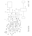
- FIG. 1 is a schematic cross-sectional view of a clutch hub according to a first embodiment of the present disclosure and a drive system incorporating a two-speed transmission including the clutch hub.
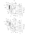
- FIG. 2(a) is a schematic cross-sectional view showing the torque transmission path in a low reduction ratio mode of the two-speed transmission of the first example
- FIG. 2(b) is a schematic cross-sectional view showing the torque transmission path in a high reduction ratio mode of the two-speed transmission of the first example.
- FIG. 3 is a cross-sectional view of the two-speed transmission of the first example.
- FIG. 4 is a cross-sectional view of the two-speed transmission of the first example with some parts omitted.
- FIG. 1 is a schematic cross-sectional view of a clutch hub according to a first embodiment of the present disclosure and a drive system incorporating a two-speed transmission including the clutch hub.
- FIG. 2(a) is a schematic cross-sectional view showing the torque transmission path in a low reduction ratio mode
- FIG. 5 is an exploded perspective view showing the first and second friction plates constituting the friction clutch device of the two-speed transmission of the first example.
- FIG. 6 is an enlarged view of part A in FIG.
- FIG. 7 is a perspective view showing a drive cam taken out from a pressing device constituting the friction clutch device.
- FIG. 8 is an exploded perspective view showing the driven cam and the rolling elements taken out from the pressing device.
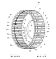
- FIG. 9 is a perspective view of the clutch hub of the first example.
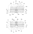
- FIG. 10 is a cross-sectional view of the clutch hub of the first example.
- 11A is an enlarged view of a portion B1 in FIG. 10
- FIG. 11B is an enlarged view of a portion B2 in FIG.
- FIG. 12(a) is a schematic cross-sectional view showing the torque transmission path in a low reduction ratio mode of a two-speed transmission of a second example of an embodiment of the present disclosure
- FIG. 12(b) is a schematic cross-sectional view showing the torque transmission path in a high reduction ratio mode of the two-speed transmission of the second example
- FIG. 13 is a perspective view of a clutch hub according to a third example of an embodiment of the present disclosure.
- FIG. 14 is a cross-sectional view of a clutch hub according to the third embodiment.
- 15A is an enlarged view of a portion C1 in FIG. 14, and
- FIG. 15B is an enlarged view of a portion C2 in FIG. FIG.
- FIG. 16 is a perspective view of a clutch hub according to a fourth embodiment of the present disclosure.
- FIG. 17 is a perspective view of a clutch hub according to a fifth example of an embodiment of the present disclosure.
- FIG. 18 is a cross-sectional view of a clutch hub according to the fifth embodiment.
- FIG. 19 is a cross-sectional view of a clutch hub according to a sixth example of an embodiment of the present disclosure.
- FIG. 20 is an enlarged view of part D in FIG.
- FIG. 21 is a perspective view of a clutch hub of a first example of a conventional structure.
- Figure 22(a) is a view of a circumferential portion of a radially outer end portion of a clutch hub of a second example of a conventional structure, as viewed from the axial direction
- Figure 22(b) is a cross-sectional view taken along line E-E of Figure 22(a).
- the two-speed transmission 1 of this example is a two-speed transmission that can be applied to automobiles including electric vehicles and hybrid vehicles, and is disposed between a drive source 2 such as an electric motor or an engine, and a differential device 3, and transmits the output torque of the drive source 2 to the differential device 3 while increasing (decelerating) or without increasing it.
- a drive source 2 such as an electric motor or an engine
- a differential device 3 transmits the output torque of the drive source 2 to the differential device 3 while increasing (decelerating) or without increasing it.
- the two-speed transmission 1 includes an input member 4, an output member 5, a rotating member 6, a friction engagement portion 46, an engagement device 8, and a planetary reduction mechanism 9.
- the axial direction, radial direction, and circumferential direction refer to the axial direction, radial direction, and circumferential direction of the input member 4.
- the axial direction, radial direction, and circumferential direction of the input member 4 coincide with the axial direction, radial direction, and circumferential direction of the output member 5, and also coincide with the axial direction, radial direction, and circumferential direction of the rotating member 6.
- one axial side refers to the right side in Figs. 1 to 4
- the other axial side refers to the left side in Figs. 1 to 4.
- the input member 4 is rotatably supported by a fixed portion 72 that does not rotate even when in use.
- the input member 4 can be rotatably driven by the driving source 2, and the output torque of the driving source 2 is input to the input member 4.
- the input member 4 is formed of a housing that contains the two-speed transmission 1, and is rotatably supported by a rolling bearing (not shown) or the like by the fixed portion 72 that does not rotate even when in use.
- the input member 4 is configured to be cylindrical (hollow).
- the input member 4 also has an input gear 12 at one axial end that meshes with a drive gear 11 provided on the output shaft 10 of the drive source 2.
- the output member 5 is supported coaxially with the input member 4 and capable of relative rotation with respect to the input member 4.
- the output member 5 is connected to the input portion of the differential device 3 so as to be capable of transmitting torque.
- the output member 5 is supported radially inside the cylindrical input member 4 via a planetary reduction mechanism 9 so as to be capable of relative rotation with respect to the input member 4.
- the output member 5 also has an output gear 13 at one end on one axial side. The output gear 13 meshes with a gear provided in the input portion of the differential device 3.
- the rotating member 6 is supported coaxially with the input member 4 and the output member 5 and is capable of relative rotation with respect to the input member 4 and the output member 5.
- the rotating member 6 is supported rotatably with respect to the fixed part 72 via the planetary reduction mechanism 9, the pressing device 49 constituting the friction clutch device 7, the bearing device 67, etc.
- the frictional engagement portion 46 has at least one first friction plate 55 and one second friction plate 56 that are supported to allow relative axial displacement.
- the frictional engagement portion 46 is formed by stacking multiple first friction plates 55 and multiple second friction plates 56 alternately.
- the frictional engagement portion 46 is provided between the input member 4 or the output member 5 and the rotating member 6, and has the function of pressing the first friction plate 55 and the second friction plate 56 against each other to switch to a state in which the input member 4 or the output member 5 and the rotating member 6 rotate together, and releasing the force pressing the first friction plate 55 and the second friction plate 56 against each other to switch to a state in which the input member 4 or the output member 5 and the rotating member 6 rotate relatively.
- the frictional engagement portion 46 is provided between the input member 4 and the rotating member 6, and has the function of pressing the first friction plate 55 and the second friction plate 56 against each other to switch to a state in which the input member 4 and the rotating member 6 rotate together, and releasing the force pressing the first friction plate 55 and the second friction plate 56 against each other to switch to a state in which the input member 4 and the rotating member 6 rotate relatively.
- the engagement device 8 is provided between the fixed part 72 and the rotating member 6, and has the function of switching between a state in which the rotating member 6 can rotate relative to the fixed part 72 and a state in which it cannot rotate.
- the planetary reduction mechanism 9 has a sun element 105, a ring element 106 arranged around the sun element 105, a carrier 107 arranged between the sun element 105 and the ring element 106 in the radial direction, and a plurality of planetary elements 108 that engage with the sun element 105 and the ring element 106 to enable torque transmission and are rotatably supported by the carrier 107.
- the input member 4, the output member 5, the first friction plate 55 and the second friction plate 56 of the friction engagement portion 46, and the outer diameter side member 101 and the inner diameter side member 102 of the engagement device 8 are connected to the sun element 105, the ring element 106, the carrier 107, or the fixed portion 72 so that the reduction ratio between the input member 4 and the output member 5 can be switched between two levels, high and low, by switching the mode of the friction engagement portion 46 and the mode of the engagement device 8.
- an input element which is any one of sun element 105, ring element 106, and carrier 107
- An output element which is any one of sun element 105, ring element 106, and carrier 107 and is an element other than said input element
- a rotating element which is the remaining element excluding said input element and said output element, among sun element 105, ring element 106, and carrier 107, is connected to rotating member 6 so as to rotate integrally with said rotating member 6.
- the ring element 106 can be connected to the input member 4 so as to rotate integrally therewith, the carrier 107 can be connected to the output member 5 so as to rotate integrally therewith, and the sun element 105 can be connected to the rotating member 6 so as to rotate integrally therewith.
- the sun element 105 can be connected to the input member 4 to rotate integrally therewith
- the carrier 107 can be connected to the output member 5 to rotate integrally therewith
- the ring element 106 can be connected to the rotating member 6 to rotate integrally therewith.
- the sun element 105 can be connected to the input member 4 to rotate integrally therewith, the ring element 106 can be connected to the output member 5 to rotate integrally therewith, and the carrier 107 can be connected to the rotating member 6 to rotate integrally therewith.
- the two-speed transmission 1 of this example is particularly characterized in that the rotating member 6 is configured to include the clutch hub 15 of this example.
- the rotating member 6 is constructed by connecting and fixing the shaft member 14 and the clutch hub 15.
- the shaft member 14 has a stepped cylindrical shape. Specifically, from one axial end, the shaft member 14 has a large diameter cylindrical section 16, a medium diameter cylindrical section 17, and a small diameter cylindrical section 18. The shaft member 14 also has a through hole 19 that passes through the center in the axial direction and allows the lubricating oil to flow.
- the large diameter cylindrical portion 16 has a locking groove 20 around the entire circumference on the outer circumferential surface of one axial side portion.
- the large diameter cylindrical portion 16 also has a protrusion 21 around the entire circumference at the end on the other axial side that protrudes radially outward beyond the portion adjacent to the one axial side.
- the protrusion 21 has a mating surface portion 22 provided on the outer circumferential surface of the one axial side portion, and a step surface 23 that bends radially outward from the end on the other axial side of the mating surface portion 22 and faces the one axial side.
- the clutch hub 15 of this example has a cylindrical portion 24 and a side plate portion 25 that extends radially inward from one axial end of the cylindrical portion 24 .
- the tubular portion 24 is generally cylindrical in shape and has a first engagement portion 26, a second engagement portion 27, an oil hole 28, and a blocking surface 29.
- the first engagement portion 26 is disposed on one axial side of the outer circumferential surface of the cylindrical portion 24.
- a component constituting the friction clutch device 7 engages with the first engagement portion 26.
- the second friction plate 56 constituting the friction clutch device 7 engages with the first engagement portion 26.
- the second engagement portion 27 is disposed on the other axial side portion of the outer circumferential surface of the cylindrical portion 24. A component constituting a device other than the friction clutch device is engaged with the second engagement portion 27. In this example, the inner diameter side member 102 of the engagement device 8 is engaged with the second engagement portion.
- the oil holes 28 penetrate radially through multiple locations in the cylindrical portion 24 in the same axial range as the first engagement portion 26.
- the clutch hub 15 of this example is characterized by having a damming surface 29.
- the damming surface 29 is provided on the inner circumferential surface of the cylindrical portion 24 in an axially intermediate portion located on the other axial side of the oil hole 28, and faces one axial side.
- the damming surface 29 has a structure in which its inner diameter is equal to or smaller than the smallest inner diameter of the portion of the inner circumferential surface of the cylindrical portion 24 located on one axial side of the damming surface 29.
- the clutch hub 15 is provided with a damming surface 29 along the entire circumference or along a portion of the circumference.
- the clutch hub 15 is applied to a two-speed transmission 1 for an automobile.
- the clutch hub 15 in this example can be incorporated into various mechanical devices that are not limited to two-speed transmissions for automobiles and that include a friction clutch device that switches whether or not a second member can rotate relative to a first member, and an engagement device that switches whether or not a third member can rotate relative to the first member.
- the configuration of the cylindrical portion 24, specifically, the structure of the outer peripheral surface and/or the inner peripheral surface of the cylindrical portion 24, can take various structures depending on the structure of the member to which the clutch hub 15 is attached, or the structure of the member to be attached to the first engagement portion 26 and the second engagement portion 27.
- the structure of the outer peripheral surface and/or the inner peripheral surface of the cylindrical portion 24 can be any structure such as a spline structure in which recesses and protrusions are alternately arranged in the circumferential direction, a structure consisting of a single cylindrical surface, or another structure in which an engagement structure with a mating member is provided on a single cylindrical surface.
- the cylindrical portion 24 has a male spline portion 30 on its outer circumferential surface, in which recesses 31 and protrusions 32 are arranged alternately in the circumferential direction.
- the first engagement portion 26 is formed by one axial side portion of the male spline portion 30, and the second engagement portion 27 is formed by the other axial side portion of the male spline portion 30.
- the cylindrical portion 24 has locking grooves 33a, 33b in the outer peripheral surface on both axial sides of the second engagement portion 27.
- the locking grooves 33a, 33b are formed by locking groove pieces that are formed so as to circumferentially cross each of the multiple protrusions 32 that make up the male spline portion 30.
- the shape and size of the oil holes 28 are arbitrary as long as they allow the lubricating oil to flow out appropriately, and the opening shape of each of the oil holes 28 as viewed from the radial direction can be an oval, a circle, a rectangle, or the like that extends in the axial direction as viewed from the radial direction.
- the opening shape of the oil holes 28 is an oval that extends in the axial direction.
- the oil holes 28 may be arranged in any manner as long as the lubricating oil can be appropriately discharged.
- the oil holes 28 may be arranged at multiple locations in the circumferential direction on one axial side of the cylindrical portion 24, one at a time, or multiple oil holes 28 may be arranged at the same circumferential location. In this example, the oil holes 28 are arranged at multiple locations in the circumferential direction, one at a time.
- the oil holes 28 can be arranged so that the axial positions of adjacent oil holes 28 in the circumferential direction are offset from each other, or they can be arranged so that their axial positions coincide with each other. In this example, the oil holes 28 are arranged so that the axial positions of adjacent oil holes 28 in the circumferential direction are offset from each other.
- the cylindrical portion 24 further has a one-side uneven portion 34, an other-side uneven portion 35, a circumferential convex wall portion 36, and a plurality of circumferential groove pieces 117.
- the one-side uneven portion 34 is provided on a portion of the inner circumferential surface of the cylindrical portion 24 that overlaps radially with the first engagement portion 26, and is composed of concave portions 38 and convex portions 39 arranged alternately in the circumferential direction.
- the recess 38 that constitutes the one-side uneven portion 34 is arranged in a portion that overlaps radially with the protrusion 32 that constitutes the male spline portion 30, and the protrusion 39 that constitutes the one-side uneven portion 34 is arranged in a direction that overlaps radially with the recess 31 that constitutes the male spline portion 30.
- the oil holes 28 are arranged one by one at the same circumferential position as the recesses 38 of the one-side uneven portion 34.
- the radially inner end of each oil hole 28 opens into the recesses 38 of the one-side uneven portion 34, and the radially outer end of each oil hole 28 opens into the protrusions 32 of the male spline portion 30.
- the other side uneven portion 35 is provided on a portion of the inner circumferential surface of the cylindrical portion 24 that overlaps radially with the second engagement portion 27, and is composed of concave portions 40 and convex portions 41 arranged alternately in the circumferential direction.
- the recess 40 that constitutes the other side uneven portion 35 is arranged in a portion that overlaps radially with the protrusion 32 that constitutes the male spline portion 30, and the protrusion 41 that constitutes the other side uneven portion 35 is arranged in a direction that overlaps radially with the recess 31 that constitutes the male spline portion 30.
- the inscribed circle diameter of the bottom surface of the recess 38 of the one-side uneven portion 34 and the inscribed circle diameter of the bottom surface of the recess 40 of the other-side uneven portion 35 are equal to each other. Also, the inscribed circle diameter of the radially inner surface of the protrusion 39 of the one-side uneven portion 34 and the inscribed circle diameter of the radially inner surface of the protrusion 41 of the other-side uneven portion 35 are equal to each other.
- the tubular portion 24 has an end face shape that is wavy in a generally rectangular wave shape in the circumferential direction when viewed from the axial direction.
- the thickness of the tubular portion 24 is generally constant around the entire circumference, making it easier to reduce the weight of the tubular portion 24.
- the circumferential convex wall portion 36 is formed on the inner surface of the cylindrical portion 24 in a portion adjacent to one axial side of the other-side uneven portion 35.
- the circumferential convex wall portion 36 is provided around the entire circumference in a portion that radially overlaps with the locking groove 33a on one axial side of the two locking grooves 33a, 33b provided on the outer surface of the cylindrical portion 24.
- the inner diameter of the circumferential convex wall portion 36 can be smaller than the inner diameter of the convex portion 39 of the one-side uneven portion 34 and the convex portion 41 of the other-side uneven portion 35, more specifically, the inscribed circle diameter of the radially inner surface of the convex portion 39 of the one-side uneven portion 34 and the inscribed circle diameter of the radially inner surface of the convex portion 41 of the other-side uneven portion 35 (the circumferential convex wall portion 36 protrudes toward the inner diameter further than the convex portions 39 and 41), or it can be equal (the radially inner surface of the circumferential convex wall portion 36 is arranged on the same imaginary cylindrical surface as the radially inner surface of the convex portion 39 and the radially inner surface of the convex portion 41), or it can be larger (the circumferential convex wall portion 36 is recessed
- the inner diameter of the radially inner surface which is the inner peripheral surface of the circumferential convex wall portion 36, is equal to the inscribed circle diameter of the radially inner surface of the convex portion 39 of the one-side uneven portion 34 and the inscribed circle diameter of the radially inner surface of the convex portion 41 of the other-side uneven portion 35. Therefore, the radially inner surface of the convex portion 41 of the other-side uneven portion 35 and the radially inner surface of the circumferential convex wall portion 36 are smoothly continuous without any steps.
- the end of the convex portion 41 of the other-side uneven portion 35 on one axial side is continuous with the end of the circumferential convex wall portion 36 on the other axial side (the radial inner surface of the convex portion 41 and the radial inner surface of the circumferential convex wall portion 36 are smoothly continuous without any steps).
- the inner diameter of the concave portion 40 of the other-side uneven portion 35 more specifically, the inner diameter of the radial inner surface of the concave portion 40, is larger than the inner diameter of the circumferential convex wall portion 36. Therefore, the end of the concave portion 40 on one axial side is blocked by the side surface of the circumferential convex wall portion 36 on the other axial side.
- the circumferential groove 37 is formed in the portion of the inner surface of the tubular portion 24 between the one-side uneven portion 34 and the other-side uneven portion 35. More specifically, the circumferential groove 37 is formed in a portion adjacent to one axial side of the circumferential convex wall portion 36, or in the axial middle portion of the circumferential convex wall portion 36.
- the circumferential groove 37 is formed at the other axial end of the convex portion 39 of the one-side uneven portion 34 so as to circumferentially cross the other axial end of the convex portion 39. Therefore, the circumferential groove 37 is disposed adjacent to one axial side of the circumferential convex wall portion 36. More specifically, the circumferential groove 37 is constituted by circumferential groove pieces 117 formed at the other axial end of each of the convex portions 39 of the one-side uneven portion 34.
- the shape of the circumferential groove 37 is arbitrary as long as the side surface on the other axial side of the circumferential groove 37 can form the blocking surface 29.
- the shape of the circumferential groove 37 may be a concave arc, a concave rectangle, a V-shape, or other cross-sectional shape.
- the circumferential groove 37 (circumferential groove piece 117) has a concave arc cross-sectional shape with the deepest part being the axial center, as shown in FIG. 11(a).
- the size of the circumferential groove 37 is arbitrary as long as the side surface on the other axial side of the circumferential groove 37 can form the damming surface 29.
- the radial depth of the circumferential groove 37 can be shallower than the radial depth of the recess 38 of the one-side uneven portion 34, the same as the radial depth of the recess 38, or deeper than the radial depth of the recess 38.
- the radial depth of the circumferential groove 37 (the radial depth of the deepest part) is shallower than the recess 38 of the one-side uneven portion 34.
- the damming surface 29 is composed of the surface of the inner surface of the circumferential groove 37 facing one axial side and the side surface of the circumferential convex wall portion 36 on one axial side. That is, for the lubricating oil flowing in the other axial direction through the recess 38 of the one-side uneven portion 34, the side surface on one axial side of the circumferential convex wall portion 36 that blocks the end portion on the other axial side of the recess 38 functions as the damming surface 29. Also, for the lubricating oil flowing in the other axial direction through the protrusion 39 of the one-side uneven portion 34, the surface of the inner surface of the circumferential groove 37 facing one axial side functions as the damming surface 29.
- the inner diameter of the damming surface 29 is equal to or smaller than the inner diameter of the smallest inner diameter portion of the inner circumferential surface of the tubular portion 24 located on one axial side of the damming surface 29.
- the inner diameter of the damming surface 29 is the same as the inscribed circle diameter of the convex portion 39, which is the smallest inner diameter portion of the inner circumferential surface of the tubular portion 24 located on one axial side of the damming surface 29.
- the damming surfaces 29 are formed around the entire circumference, i.e., the damming surfaces 29 can be arranged on all of the recesses 38 and protrusions 39 of the one-side uneven portion 34.
- the damming surfaces 29 can be arranged only on some of the recesses 38 in the circumferential direction among the recesses 38 of the one-side uneven portion 34.
- the damming surfaces 29 are arranged on all of the protrusions 39 of the one-side uneven portion 34, but not on some of the recesses 38.
- No oil holes 28 are arranged in some of the recesses 38 where the damming surfaces 29 are not formed, and the oil holes 28 can be arranged only in the remaining parts of the recesses 38 where the damming surfaces 29 are formed.
- the circumferential convex wall portion 36 is formed around the entire circumference of the inner surface of the tubular portion 24 in a portion adjacent to one axial side of the other-side uneven portion 35, and the circumferential groove 37 (circumferential groove piece 117) is formed at the other axial end of all the recesses 38 of the one-side uneven portion 34.
- the side plate portion 25 is configured as a hollow circular plate, and has through holes 42 that penetrate in the axial direction at multiple locations around the circumference of the radially middle portion.
- the shaft member 14 and the clutch hub 15 are fixed together by welding or the like with the radially inner portion of the other axial side surface of the side plate portion 25 abutting against the step surface 23 and the inner peripheral surface of the side plate portion 25 fitted onto the mating surface portion 22.
- lubricating oil is supplied to the radially inner region of the cylindrical portion 24 of the clutch hub 15 through a lubrication path such as the through hole 19 of the shaft member 14.
- the lubricating oil supplied to the radially inner region of the cylindrical portion 24 moves radially outward from the region to the inner circumferential surface of the cylindrical portion 24 due to the action of centrifugal force and gravity, as shown by arrows ⁇ 1 and ⁇ 2 in Figure 10.
- a portion of the lubricating oil supplied to the inner circumferential surface of the cylindrical portion 24 of the clutch hub 15, specifically, the lubricating oil supplied to one axial side of the dam surface 29 of the inner circumferential surface of the cylindrical portion 24 of the clutch hub 15, is collected in the recesses 38 of the one-side uneven portion 34 by the action of centrifugal force and gravity, and is then allowed to flow out radially outward of the cylindrical portion 24 through the oil hole 28 as shown by the arrow ⁇ 1 in FIG. 10, thereby lubricating the friction engagement portion 46 having the first friction plate 55 and the second friction plate 56.
- the remaining portion of the lubricating oil supplied to the inner circumferential surface of the cylindrical portion 24 of the clutch hub 15, specifically, the lubricating oil supplied to the inner circumferential surface of the cylindrical portion 24 of the clutch hub 15 on the other axial side of the damming surface 29, is collected in the recess 40 of the other side uneven portion 35 by the action of centrifugal force and gravity, moves along the inner surface of the recess 40 to the other axial side, and flows out from the inner circumferential surface of the cylindrical portion 24, and further moves radially outward of the cylindrical portion 24 along the end face on the other axial side of the cylindrical portion 24 as shown by arrow ⁇ 2 in FIG. 10, thereby lubricating the engagement device 8 including the inner diameter side member 102.
- a damming surface 29 facing one axial side is present around the entire circumference of the inner circumferential surface of the cylindrical portion 24 in an axially intermediate portion located on the other axial side of the oil hole 28. Therefore, the damming surface 29 can prevent lubricating oil supplied to the inner circumferential surface of the cylindrical portion 24 on one axial side of the damming surface 29 from moving along the inner circumferential surface of the cylindrical portion 24 to the other axial side of the damming surface 29.
- the lubricating oil that enters the recess 38 of the one-side uneven portion 34 and moves to the other axial direction side is blocked by the side surface of the damming surface 29 on one axial direction side of the circumferential convex wall portion 36 that exists in the same circumferential position as the recess 38.
- the lubricating oil that moves to the other axial direction side along the radial inner surface of the convex portion 39 that constitutes the one-side uneven portion 34 is blocked by the surface of the damming surface 29 facing one axial direction side of the circumferential groove piece 117 that exists in the same circumferential position as the convex portion 39.
- the lubricating oil supplied to the inner circumferential surface of the cylindrical portion 24 on one axial side of the damming surface 29 can be prevented from moving along the inner circumferential surface of the cylindrical portion 24 to the other axial side of the damming surface 29.
- a friction clutch device 7 is configured between the input member 4 and the rotating member 6.
- the friction clutch device 7 has a function of switching between a connected mode in which the input member 4 and the rotating member 6 rotate integrally, and a disconnected mode in which the input member 4 and the rotating member 6 rotate relative to each other.
- the friction clutch device 7 includes a first member 43, a rotating member 6 which is a second member, a retaining ring 44, a stop ring 45, a friction engagement portion 46, a pressure plate 47, an elastic member 48, and a pressure device 49.
- the first member 43 is connected to the input member 4 and rotates integrally with the input member 4.
- the first member 43 has a stepped cylindrical shape. Specifically, the first member 43 is configured by connecting a large diameter cylindrical portion 50 on one axial side and a small diameter cylindrical portion 51 on the other axial side by a hollow circular plate-shaped connecting plate portion 52.
- the first member 43 is connected to the input member 4 via a connecting member 53, which is generally configured as a hollow disk. Specifically, the radially outer end of the connecting member 53 is fitted and fixed to one axial end of the large-diameter cylindrical portion 50 of the first member 43, and the radially inner end of the connecting member 53 is fitted and fixed to the outside of the axial middle portion of the input member 4, so that the first member 43 is connected to the input member 4 so as to be rotatable together with it.
- the first member 43 has a female spline portion 54 on the inner surface of the small diameter cylindrical portion 51, in which recesses and protrusions are arranged alternately in the circumferential direction.
- the retaining ring 44 is fitted onto the outer circumferential surface of the large-diameter cylindrical portion 16 of the rotating member 6, on the other axial side of the locking groove 20, without any radial play and allowing relative axial displacement.
- the retaining ring 45 is engaged with the retaining groove 20 of the rotating member 6, preventing the retaining ring 44 from being displaced in one axial direction.
- the first friction plate 55 constituting the friction engagement portion 46 has an end face shape that is approximately hollow and circular when viewed from the axial direction.
- the outer periphery of the first friction plate 55 is spline-engaged with the female spline portion 54 of the first member 43, so that it is supported in such a way that it can be displaced in the axial direction but cannot rotate relative to the small diameter cylindrical portion 51 of the first member 43.
- the second friction plate 56 constituting the friction engagement portion 46 has an end face shape that is approximately hollow and circular when viewed from the axial direction.
- the inner periphery of the second friction plate 56 is spline-engaged with the first engagement portion 26 of the cylindrical portion 24 of the rotating member 6, which is the second member, so that the second friction plate 56 is supported in such a way that it can be displaced in the axial direction but cannot rotate relative to the cylindrical portion 24 of the rotating member 6.
- the friction plate located furthest to the other axial direction among the first friction plate 55 and the second friction plate 56 (among the plurality of first friction plates 55 and the plurality of second friction plates 56) is prevented from being displaced to the other axial direction by abutting the side surface on the other axial direction against the side surface on one axial direction of the annular retaining member 57 that is fitted to the outside of the cylindrical portion 24 so as to be unable to rotate relative to the cylindrical portion 24 and to be unable to be displaced to the other axial direction.
- the retaining member 57 is prevented from rotating relative to the tubular portion 24 by spline-engaging the inner periphery with the first engagement portion 26, and is prevented from displacing axially to the other side relative to the tubular portion 24 by a retaining ring 104a that is engaged with the engagement groove 33a of the tubular portion 24.
- the friction engagement portion 46 may additionally include, as an optional component, a return spring that elastically biases the first friction plate 55 and the second friction plate 56 in a direction separating them from each other.
- the pressure plate 47 faces one axial side of the friction plate that is located furthest to one axial side of the first friction plate 55 and the second friction plate 56, and is fitted onto the rotating member 6, which is the second member, so as to be capable of axial movement toward and away from the friction plate located furthest to one axial side.
- the pressure plate 47 has a circular ring portion 58 that has an end face shape that is approximately hollow and circular when viewed from the axial direction, and a cylindrical portion 59 that extends from the radially outer end of the circular ring portion 58 toward the other axial side.
- the circular ring portion 58 is fitted onto the axial middle portion of the large diameter cylindrical portion 16 of the rotating member 6 so as to allow relative axial displacement.
- the radially inner end of the side surface on the other axial side of the circular ring portion 58 faces the side surface on one axial side of the protruding portion 21. This prevents excessive displacement of the pressure plate 47 towards the other axial side.
- the other axial end face of the cylindrical portion 59 faces one axial side face of the friction plate that is located furthest axially toward one side of the first friction plate 55 and the second friction plate 56.
- the elastic member 48 is sandwiched between the retaining ring 44 and the pressure plate 47, and elastically biases the pressure plate 47 toward the other axial side. That is, the elastic member 48 applies elasticity to the first friction plate 55 and the second friction plate 56 in a direction in which they press against each other by using the pressure plate 47 to press the friction plate located furthest to the one axial side out of the first friction plate 55 and the second friction plate 56 toward the other axial side.
- the configuration of the elastic member 48 is not limited and can be any desired configuration, such as a disc spring, a compression coil spring, or any other desired elastic material.
- the number of pieces of elastic material that make up the elastic member is also arbitrary.
- the elastic member 48 is made up of one or more disc springs.
- the pressing device 49 presses the pressing plate 47 toward one side in the axial direction.
- the pressing device 49 includes a cam device 60 and a device for driving the cam device 60, such as an electric actuator 61.
- the cam device 60 includes a driving cam 62, a driven cam 63, and a number of rolling elements 64.
- rollers are used as the rolling elements 64, and the rolling elements 64 are supported for free rotation (self-spin) around a rotation axis C that faces in a radial direction from the central axis of the driven cam 63, relative to the driven cam 63.
- the cam device 60 is shown diagrammatically to make it easier to understand the invention.
- the drive cam 62 has a drive cam surface 65 on the radially inner portion of one axial side surface, in which an equal number of recesses 65a and protrusions 65b are arranged alternately in the circumferential direction.
- the drive cam 62 is supported by a support member 66, a bearing device 67, and a radial bearing 68 so that it can rotate relative to the rotating member 6. Note that the support member 66 and the bearing device 67 are not shown in FIGS. 1 to 2(b).
- the support member 66 has a circular ring portion 69 that has a hollow circular end face shape when viewed from the axial direction, and a cylindrical portion 70 that is bent from the radially inner end of the circular ring portion 69 toward one side in the axial direction.
- the support member 66 is supported and fixed to the fixed portion 72 by bolts (not shown) that are inserted or screwed into mounting holes 71 provided at multiple locations around the circumference of the ring portion 69.
- the bearing device 67 is composed of a double row ball bearing, and includes an inner ring 73 fitted onto the small diameter cylindrical portion 18 of the rotating member 6, an outer ring 74 fitted onto the cylindrical portion 70 of the support member 66, and a number of rolling elements 75 arranged to roll freely between the inner ring 73 and the outer ring 74.
- the radial bearing 68 is an angular ball bearing, and includes an inner ring 76 fitted onto the other axial side of the cylindrical portion 70 of the support member 66, an outer ring 77 fitted onto the drive cam 62, and a number of balls 78 arranged to roll freely between the inner ring 76 and the outer ring 77.
- the drive cam 62 has wheel teeth 79, which are helical gears, on its outer circumferential surface, and has pin portions 80 that protrude toward one axial direction at multiple circumferential locations (three locations in the illustrated example) in the radially middle portion of the side surface on one axial direction side.
- the tip of the pin portion 80 engages (fits with play) with an engagement hole provided in the select plate 103 that constitutes the engagement device 8. This causes the drive cam 62 and the select plate 103 to rotate integrally (in the same direction at the same speed).
- the driven cam 63 is configured as a hollow circular plate, has rectangular holes 81 penetrating in the axial direction at multiple locations (three locations in the illustrated example) around the radial middle portion, and has support plate portions 82a, 82b in the shape of approximately semicircular plates that protrude from both radial sides of each rectangular hole 81 toward the other axial side.
- Each of the support plate portions 82a on the radial outside has a support hole 83a that is a circular hole penetrating in the radial direction
- each of the support plate portions 82b on the radial inside has a support hole 83b that is a circular hole penetrating in the radial direction.
- the driven cam 63 is arranged around the rotating member 6 so that it can only be displaced in the axial direction. Specifically, the driven cam 63 is supported so that it can only be displaced in the axial direction relative to the fixed portion 72 by spline-engaging a female spline portion 84 provided on the inner peripheral surface with a male spline portion 85 provided on the outer peripheral surface of one axial side portion of the cylindrical portion 70 of the support member 66, which is supported and fixed to the fixed portion 72.
- Each of the rolling elements 64 has a cylindrical shape and is supported for free rotation on the support plate portions 82a and 82b via a cylindrical support shaft 86 and a plurality of rollers 87. That is, both ends of the support shaft 86 in the axial direction are fitted and fixed in the support holes 83a and 83b.
- the rollers 87 are sandwiched between the inner peripheral surface of the rolling element 64 and the outer peripheral surface of the axial middle portion of the support shaft 86 for free rolling.
- the rolling element 64 is supported by the driven cam 63 for free rotation (spin) around the rotation axis C that faces in the radial direction from the central axis of the driven cam 63.
- the other axial end of the outer peripheral surface of each rolling element 64 is in rolling contact with the driving cam surface 65 provided on the side surface on one axial side of the driving cam 62.
- the rolling elements 64 that make up the cam device 60 are not limited to rollers and can be configured as desired, and can be balls instead of rollers.
- a driven cam surface is formed on the side surface on the other axial side of the driven cam, in which the same number of recesses and protrusions are alternately arranged in the circumferential direction.
- the driving cam 62 rotates, the amount by which the rolling element 64 rides up from the bottom of the recess 65a that constitutes the driving cam surface 65 increases or decreases, displacing the driven cam 63 in the axial direction.
- the driven cam 63 presses the pressure plate 47 toward one side in the axial direction via the pressure member 88 and the thrust bearing 89.
- the pressing member 88 has a base 90 and multiple pressing arms 91.
- the base 90 has an inner diameter side plate portion 92 in the form of a hollow circular plate, a cylindrical connecting tube portion 93 extending from the radially outer end portion of the inner diameter side plate portion 92 toward one axial direction side, and a hollow circular plate-like outer diameter side plate portion 94 extending from the axially outer end portion of the connecting tube portion 93 toward one axial direction side.
- the inner diameter side plate portion 92 of the base 90 is fitted onto the medium diameter tube portion 17 of the rotating member 6 without any radial rattle and allowing relative axial displacement.
- Each pressing arm 91 protrudes from the radially outer end of the outer diameter side plate portion 94 of the base 90 toward one axial side.
- Each pressing arm 91 is inserted into a through hole 42 provided in the side plate portion 25 of the clutch hub 15, and the tip surface faces the radially middle portion of the side surface on the other axial side of the circular ring portion 58 of the pressing plate 47.
- the thrust bearing 89 is constructed by arranging a number of rolling elements 96 freely rollable between a pair of raceways 95a, 95b that are spaced apart in the axial direction and arranged coaxially.
- the thrust bearing 89 is arranged between one axial side surface of the driven cam 63 and the other axial side surface of the outer diameter side plate portion 94 of the pressing member 88.
- the friction clutch device 7 of this example includes a preload applying member 97 for applying a preload to the thrust bearing 89, regardless of the axial dimension of the cam device 60.
- the preload applying member 97 is composed of a plurality of disc springs, compression coil springs, etc. In this example, the preload applying member 97 is composed of a plurality of disc springs.
- the preload applying member 97 is sandwiched in an elastically compressed state between one axial side surface of the inner diameter side plate portion 92 of the pressing member 88 and the other axial end surface of the large diameter cylindrical portion 16 of the rotating member 6.
- the preload applying member 97 elastically presses the pressing member 88 toward the other axial side by attempting to return to its original shape. This applies a preload to the thrust bearing 89 and prevents the thrust bearing 89 from falling out from between the driven cam 63 and the pressing member 88.
- the cam device 60 is driven by an arbitrary drive device.
- the drive cam 62 is rotated and driven by an electric actuator 61.
- the electric actuator 61 includes an electric motor 98 and a reducer 99.
- the reducer 99 is configured by meshing a worm 100, which is rotated and driven by the electric motor 98, with wheel teeth 79 provided on the outer circumferential surface of the drive cam 62.
- a structure in which a spur gear or bevel gear on the output shaft of the electric motor meshes with a spur gear or bevel gear on the drive cam 62, or a structure in which a belt or chain is stretched between the output shaft of the electric motor and the drive cam 62 can be used.
- the cam device 60 may be a structure in which a driving cam surface on a driving cam and a driven cam surface on a driven cam are directly engaged (sliding) with each other, or a structure in which a driven cam has a guide groove that extends circumferentially on its outer circumferential surface and varies in the axial direction, and a driving cam has an engaging protrusion that engages to enable displacement along the guide groove.
- the pressing device 49 may be a hydraulic cylinder device, a gas pressure cylinder device (including a pneumatic cylinder device), or the like.
- the friction clutch device 7 in this example controls the supply of electricity to the electric motor 98 and adjusts the rotational phase of the drive cam 62 to switch between a connected mode in which the first member 43 and the second member, the rotating member 6, rotate together, and a disconnected mode in which the first member 43 and the rotating member 6 rotate relative to each other.
- the friction clutch device 7 can be configured to use a so-called normally open type clutch in which the friction engagement portion 46 is connected (the first friction plate 55 and the second friction plate 56 are pressed against each other) by displacing the driven cam 63 in a direction that increases the axial distance between the driving cam 62 and the driven cam 63 based on the rotation of the driving cam 62, and the friction engagement portion 46 is disconnected (the force pressing the first friction plate 55 and the second friction plate 56 against each other is released) by displacing the driven cam 63 in a direction that decreases the axial distance between the driving cam 62 and the driven cam 63.
- the friction clutch device 7 can be configured to use a so-called normally-closed clutch in which the friction engagement portion 46 is connected (the first friction plate 55 and the second friction plate 56 are pressed against each other) by displacing the driven cam 63 in a direction that reduces the axial distance between the driving cam 62 and the driven cam 63 based on the rotation of the driving cam 62, and the friction engagement portion 46 is disconnected (the force pressing the first friction plate 55 and the second friction plate 56 against each other is released) by displacing the driven cam 63 in a direction that increases the axial distance between the driving cam 62 and the driven cam 63.
- a normally-closed clutch is used. That is, to switch the friction clutch device 7 to the connection mode, the electric motor 98 is energized to rotate the driving cam 62, thereby reducing the amount of the rolling body 64 climbing up from the bottom of the recess 65a of the driving cam surface 65. As a result, the driven cam 63 releases the force pressing the pressure plate 47 toward one axial side via the pressing member 88 and the thrust bearing 89.
- the electric motor 98 is energized to rotate the driving cam 62, thereby increasing the amount by which the rolling body 64 rides over the bottom of the recess 65a of the driving cam surface 65.
- This causes the driven cam 63 to press the pressure plate 47 toward one axial side via the pressure member 88 and thrust bearing 89, elastically contracting the axial dimension of the elastic member 48 and releasing the force pressing the first friction plate 55 and the second friction plate 56 against each other.
- the gap between the first friction plate 55 and the second friction plate 56 increases, the friction clutch device 7 is disconnected, and the first member 43 and the rotating member 6 become capable of relative rotation.
- the engagement device 8 can be configured, for example, as a meshing or friction clutch (braking device) whose mode can be switched by an actuator.
- an actuator for switching the clutch between engaged and disengaged states, and a hydraulic actuator, an electromagnetic actuator, or the like can be used.
- the engagement device 8 is configured so that its mode can be switched based on the rotation of the drive cam 62 that constitutes the pressing device 49.
- the engagement device 8 includes an outer diameter side member 101 that is fitted and fixed to the inside of the fixed portion 72, an inner diameter side member 102 that is fitted and fixed to the outside of the cylindrical portion 24, at least one engagement pin (not shown), and a select plate 103.
- the inner diameter side member 102 is configured in an annular shape and has an engagement recess (not shown) on its outer circumferential surface.
- the inner diameter side member 102 is prevented from rotating relative to the tubular portion 24 by spline-engaging the inner circumferential portion with the second engagement portion 27 of the tubular portion 24.
- the inner diameter side member 102 is prevented from axial displacement relative to the tubular portion 24 by being clamped from both axial sides by two retaining rings 104a, 104b that are engaged with the engagement grooves 33a, 33b of the tubular portion 24.
- the engagement pin is detachably supported between the outer diameter side member 101 and the inner diameter side member 102.
- the engagement pin protrudes radially inward from the inner peripheral surface of the outer diameter side member 101 and is supported in a state in which it is given an elastic force directed radially inward.
- the tip of the engagement pin is capable of engaging with an engagement recess in the inner diameter side member 102.
- the select plate 103 has engagement holes (not shown) that open at multiple locations around the circumference of the other axial side. The tip of the pin 80 on the drive cam 62 is fitted into each engagement hole. This allows the select plate 103 to rotate integrally with the drive cam 62 (in the same direction and at the same speed).
- the select plate 103 has a mode select portion that is a circumferentially uneven portion.
- the engagement device 8 switches between a state in which the outer diameter side member 101 and the inner diameter side member 102 can rotate relative to each other and a state in which they cannot rotate relative to each other based on the rotation of the select plate 103. That is, based on the rotation of the select plate 103, the convex portion constituting the mode select portion pushes the engagement pin radially outward, thereby disengaging the engagement pin from the engagement recess, and switching the engagement device 8 to the disconnection mode. This allows the inner diameter side member 102 to rotate relative to the outer diameter side member 101, and allows the rotating member 6 to rotate relative to the fixed portion 72.
- the convex portion constituting the mode select portion is moved to a position circumferentially offset from the tip of the engagement pin based on the rotation of the select plate 103, thereby engaging the engagement pin with the engagement recess, and switching the engagement device 8 to the connection mode.
- This prevents rotation of the inner diameter side member 102 relative to the outer diameter side member 101, and prevents rotation of the rotating member 6 relative to the fixed portion 72.
- the planetary reduction mechanism 9 is configured as a planetary gear mechanism in which a planetary element 108 formed by a planetary gear is engaged, i.e., meshed, with a sun element 105 formed by a sun gear and a ring element 106 formed by a ring gear so as to be able to transmit torque.
- the sun element 105 is connected to the input member 4 so as to be capable of transmitting torque, and is capable of rotating integrally with the input member 4.
- the sun element 105 is integrally provided on the outer peripheral surface of the end portion on the other axial side of the input member 4.
- the ring element 106 is arranged around the sun element 105 and is coaxial with the sun element 105, and is connected to the rotating member 6 so as to be able to transmit torque, so that it can rotate integrally with the rotating member 6.
- the ring element 106 is provided on an annular member 109 that is fixedly coupled to the rotating member 6.
- the annular member 109 has a small diameter cylindrical portion 110 that is fitted and fixed to one axial end of the rotating member 6, a hollow circular plate-shaped connecting plate portion 111 that extends radially outward from one axial end of the small diameter cylindrical portion 110, and a large diameter cylindrical portion 112 that extends axially from the radially outer end of the connecting plate portion 111.
- the ring element 106 is provided integrally on the inner peripheral surface of the large diameter cylindrical portion 112.
- the carrier 107 is disposed between the sun element 105 and the ring element 106 in the radial direction, coaxially with the sun element 105 and the ring element 106, and is connected to the output member 5 so as to be capable of transmitting torque, and is rotatable integrally with the output member 5.
- the carrier 107 is provided integrally with the output member 5 at the other axial end of the output member 5.
- Each of the multiple planetary elements 108 meshes with the sun element 105 and the ring element 106, and is supported by the carrier 107 so that it can rotate (spin) around its own central axis.
- the two-speed transmission 1 of this example controls the supply of electricity to the electric motor 98 and adjusts the rotational phase of the drive cam 62 to switch between the modes of the friction clutch device 7 and the engagement device 8, making it possible to switch between a low reduction ratio mode in which the reduction ratio between the input member 4 and the output member 5 is small (reduction ratio is 1), and a high reduction ratio mode in which the reduction ratio is larger than that in the low reduction ratio mode.
- the engagement device 8 is switched to the disconnection mode, allowing the rotation member 6 to rotate relative to the fixed part 72.
- the ring element 106 is allowed to rotate relative to the fixed part 72.
- the drive cam 62 when electricity is applied to the electric motor 98, the drive cam 62 is rotated in a direction that increases the amount by which the rolling elements 64 climb above the bottom of the recess that constitutes the drive cam surface 65.
- the sun element 105 and ring element 106 become capable of rotating relative to each other.
- the engagement device 8 is switched to the connection mode, preventing the rotation member 6 from rotating relative to the fixed part 72.
- the ring element 106 is prevented from rotating relative to the fixed part 72.
- the rotational torque of the input member 4 is transmitted to the output member 5 via the path shown by the thick line in FIG. 2(b), that is, the input member 4, the sun element 105, the rotational motion of the planetary element 108, the revolutionary motion of the planetary element 108 based on the meshing with the ring element 106, and the path passing through the carrier 107.
- the rotational torque of the input member 4 is increased by the planetary reduction mechanism 9 and transmitted to the output member 5.
- the reduction ratio between the input member 4 and the output member 5 in the high reduction ratio mode is determined by the gear ratio between the ring element 106 and the sun element 105 (number of teeth of the ring element 106/number of teeth of the sun element 105).
- the two-speed transmission 1 can switch the reduction ratio between the input member 4 and the output member 5 between two levels, high and low, by switching the mode of the friction clutch device 7 and the mode of the engagement device 8. Specifically, in the region where the rotational torque input to the input member 4 is low speed and high torque, the two-speed transmission 1 is switched to a high reduction ratio mode, and in the region where the rotational torque input to the input member 4 is high speed and low torque, the two-speed transmission 1 is switched to a low reduction ratio mode. This makes it possible for the acceleration performance and high-speed performance of electric vehicles and hybrid vehicles running with only an electric motor as a drive source to be close to that of gasoline engine vehicles.
- the planetary reduction mechanism 9 can be configured as a planetary roller mechanism in which a planetary element formed by a planetary roller is engaged, i.e., in rolling contact, with a sun element formed by a sun roller and a ring element formed by a ring roller so as to be able to transmit torque.
- the sun element may be connected to the rotating member so as to be capable of transmitting torque
- the carrier may be connected to one of the input member and the output member so as to be capable of transmitting torque
- the ring element may be connected to the other of the input member and the output member so as to be capable of transmitting torque
- the clutch hub 15 of this example is applied, so the amount of lubricating oil supplied to both the friction engagement portion 46 and the engagement device 8, which are two different components that engage with the clutch hub 15, is appropriately ensured, making it possible to improve their durability.
- This example differs from the first example in that a normally open type clutch is used as the friction clutch device 7a.
- the cam device 60a is disposed on one axial side of the friction engagement portion 46. Between the driven cam 63 of the cam device 60a and the friction plate located furthest axially on one axial side out of the first friction plates 55 and the second friction plates 56 (out of the plurality of first friction plates 55 and the plurality of second friction plates 56), an elastic member 48a and a thrust rolling bearing 89a are sandwiched in that order from the one axial side.
- the elastic member 48a elastically biases the friction clutch device 7a and the driven cam 63 in a direction away from each other in the axial direction.
- the elastic member 48a is composed of a plurality of disc springs, compression coil springs, etc. In this example, the elastic member 48a is composed of a plurality of disc springs.
- the friction clutch device 7a is provided with a return spring 118 that separates the first friction plate 55 and the second friction plate 56 from each other and elastically urges the first friction plate 55 and the second friction plate 56 in a direction to release the force pressing the first friction plate 55 and the second friction plate 56 against each other.
- the return spring 118 is stretched between the friction plate located furthest on one axial side and the friction plate located furthest on the other axial side among the first friction plate 55 and the second friction plate 56 (among the plurality of first friction plates 55 and the plurality of second friction plates 56), and elastically urges the friction plate located furthest on one axial side and the friction plate located furthest on the other axial side in a direction separating them from each other.
- the driving cam 62 is rotationally driven by the electric actuator 61, thereby moving the driven cam 63 in a direction in which the axial distance between the driving cam 62 and the driven cam 63 is reduced.
- This causes the force pressing the first friction plate 55 and the second friction plate 56 against each other to be lost.
- the action of the return spring 118 increases the distance between the first friction plate 55 and the second friction plate 56, and the friction engagement portion 46 is disconnected, and the friction clutch device 7a is switched to the disconnection mode.
- the driving cam 62 is rotationally driven by the electric actuator 61, thereby moving the driven cam 63 in a direction in which the axial distance from the driving cam 62 increases.
- This causes the driven cam 63 to press the first friction plate 55 and the second friction plate 56 against each other via the elastic member 48a and the thrust rolling bearing 89a.
- the first friction plate 55 and the second friction plate 56 are pressed against each other, and the friction engagement portion 46 is connected, and the friction clutch device 7a is switched to the connection mode.
- the cylindrical portion 24a constituting the clutch hub 15a has a circumferential convex wall portion 36a on its inner surface between the one-side uneven portion 34a and the other-side uneven portion 35a, and has a circumferential groove 37a around the entire circumference in the axial middle portion of the inner surface of the circumferential convex wall portion 36a.
- the other axial end of the convex portion 39 of the one-side uneven portion 34a is continuous with the one axial end of the circumferential convex wall portion 36a (the radial inner surface of the convex portion 39 and the radial inner surface of the circumferential convex wall portion 36a are smoothly continuous without any steps), and the other axial end of the concave portion 38 of the one-side uneven portion 34a is blocked by the side surface of the one axial side of the circumferential convex wall portion 36a.
- the end of the convex portion 41 of the other side uneven portion 35a on one axial side is continuous with the end of the circumferential convex wall portion 36a on the other axial side (the radial inner surface of the convex portion 41 and the radial inner surface of the circumferential convex wall portion 36a are smoothly continuous without any steps), and the end of the concave portion 40 of the other side uneven portion 35a on one axial side is blocked by the end face of the circumferential convex wall portion 36a on the other axial side.
- the circumferential groove 37a has a cross-sectional shape that is a concave arc, with the deepest part being at the axial center.
- the damming surface 29a is composed of the surface of the inner surface of the circumferential groove 37a facing one axial direction and the side surface of the circumferential protruding wall portion 36a on one axial direction. That is, for the lubricating oil flowing in the other axial direction through the recess 38 of the one-side uneven portion 34a, the side surface on one axial direction of the circumferential protruding wall portion 36a that blocks the end portion on the other axial direction of the recess 38 functions as the damming surface 29a. Also, for the lubricating oil flowing in the other axial direction through the protrusion 39 of the one-side uneven portion 34a, the surface of the inner surface of the circumferential groove 37a facing one axial direction functions as the damming surface 29a.
- the lubricating oil that is supplied to one axial direction side of the blocking surface 29a and moves to the other axial direction side by entering the recess 38 that constitutes the one-side uneven portion 34a is blocked by the side surface of the blocking surface 29a on one axial direction side of the circumferential protruding wall portion 36a, thereby being prevented from moving further in the other axial direction.
- the lubricating oil that is supplied to one axial side of the blocking surface 29a and moves along the radial inner surface of the convex portion 39 that constitutes the one-side uneven portion 34a to the other axial side enters the circumferential groove 37a and is blocked by the surface of the inner surface of the circumferential groove 37a that faces one axial side of the blocking surface 29a, thereby preventing the lubricating oil from moving further to the other axial side.
- the cylindrical portion 24b constituting the clutch hub 15b has a circumferential convex wall portion 36b formed in only a portion of the circumferential concave portions 38 of the concave portions 38, 38a of the one-side uneven portion 34b, and a damming surface 29 is disposed therein.
- At least one of the concave portions 38, 38a of the one-side uneven portion 34b and the concave portions 40, 40a of the other-side uneven portion 35b does not have a circumferential convex wall portion 36b and a circumferential groove 37 disposed therein, and the concave portions 38a and the concave portions 40a are configured to be continuous with the same inner diameter.
- the damming surface 29 is arranged on all of the convex portions 39 of the one-side uneven portion 34b. Since the circumferential convex wall portion 36b is formed at the other axial end of some of the concave portions 38 of the one-side uneven portion 34b, the damming surface 29 is arranged on all of the concave portions 38. However, since the circumferential convex wall portion 36b does not exist in at least one of the concave portions 38a, 40a, the damming surface 29 is not arranged for the concave portion 38a of the one-side uneven portion 34b. In this example, the oil hole 28 is not arranged in the concave portion 38a where the damming surface 29 is not formed, and the oil hole 28 is arranged only in the concave portion 38 where the damming surface 29 is formed.
- the lubricating oil flowing through the recess 38a to the other axial direction flows out radially outward through the recess 40a, the end portion on the other axial end side of the cylindrical portion 24, and the end face on the other axial end side.
- the number and arrangement of the recesses 38a, 40a that do not have the oil holes 28 and the damming surface 29 are appropriately determined depending on the degree to which the amount of lubricating oil flowing out radially outward through the oil holes 28 and the amount of lubricating oil flowing out radially outward through the end portion and end face on the other axial end side of the cylindrical portion 24 are adjusted.
- the recesses 38a, 40a are provided at equal intervals at four locations in the circumferential direction.
- the cylindrical portion 24c that constitutes the clutch hub 15c has a circumferential protrusion 113 around the entire circumference at the axially middle portion of the inner surface.
- the circumferential protrusion 113 is formed around the entire periphery of the axially intermediate portion of the inner peripheral surface of the cylindrical portion 24c, more specifically, in a portion of the inner peripheral surface of the cylindrical portion 24c that radially overlaps with the locking groove 33a on one side in the axial direction of the two locking grooves 33a, 33b provided on the outer peripheral surface of the cylindrical portion 24c.
- the circumferential ridge 113 has a rectangular cross-sectional shape.
- the blocking surface 29b is formed by the side surface on one axial side of the circumferential protrusion 113.
- the portion of the inner circumferential surface of the tubular portion 24c that is axially spaced from the circumferential protrusion 113 is configured as a cylindrical surface whose inner diameter does not change along the axial direction.
- the lubricating oil supplied to one axial direction side of the blocking surface 29b is blocked by the blocking surface 29b, which is the side surface on one axial direction side of the circumferential protrusion 113, and is prevented from moving further in the other axial direction.
- the cylindrical portion 24d that constitutes the clutch hub 15d is formed by combining a cylindrical portion main body 114 and a ring-shaped member 115.
- the cylindrical body 114 has a locking groove 116 around the entire circumference at the axially middle portion of the inner surface.
- the ring-shaped member 115 has its radially outer portion locked in the locking groove 116.
- the portion of the ring-shaped member 115 that protrudes radially inward from the locking groove 116 constitutes the circumferential protrusion 113a.
- the ring-shaped member 115 has a circular ring shape that is connected all around when viewed from the axial direction.
- the ring-shaped member 115 is configured as a spiral retaining ring, which is a retaining ring made by winding a material in a spiral shape one or more times (for example, about two times).
- the blocking surface 29c is formed by the side surface on one axial side of the circumferential protrusion 113a.
- the lubricating oil supplied to one side of the blocking surface 29c in the axial direction is blocked by the blocking surface 29c and is prevented from moving further to the other side in the axial direction.
- the first to sixth examples of the embodiment may be combined as appropriate, provided no mutual contradictions arise.
- At least one of the recesses of the one-side uneven portion and the other-side uneven portion may be configured so that the circumferential convex wall portion and the circumferential groove are not disposed, and the inner diameters of these recesses are continuous and the same.
- Reference Signs List 1 Two-speed transmission 2 Driving source 3 Differential device 4 Input member 5 Output member 6 Rotating member (second member) Reference Signs List 7, 7a Friction clutch device 8 Engagement device 9 Planetary reduction mechanism 10 Output shaft 11 Drive gear 12 Input gear 13 Output gear 14 Shaft member 15, 15a, 15b, 15c, 15d Clutch hub 16 Large diameter cylindrical portion 17 Medium diameter cylindrical portion 18 Small diameter cylindrical portion 19 Through hole 20 Locking groove 21 Protruding portion 22 Fitting surface portion 23 Step surface 24, 24a, 24b, 24c, 24d Cylindrical portion 25 Side plate portion 26 First engagement portion 27 Second engagement portion 28 Oil hole 29, 29a, 29b, 29c Stop surface 30 Male spline portion 31 Recessed portion 32 Protruding portion 33a, 33b Locking groove 34, 34a, 34b One-side uneven portion 35, 35a, 35b Other-side uneven portion 36, 36a, 36b Circumferential convex wall portion 37, 37a Circumferential groove 38, 38a Recess 39 Convex portion
Landscapes
- Engineering & Computer Science (AREA)
- General Engineering & Computer Science (AREA)
- Mechanical Engineering (AREA)
- Mechanical Operated Clutches (AREA)
Priority Applications (1)
| Application Number | Priority Date | Filing Date | Title |
|---|---|---|---|
| JP2025538689A JP7740606B1 (ja) | 2023-12-01 | 2024-11-28 | クラッチハブおよび2段変速機 |
Applications Claiming Priority (2)
| Application Number | Priority Date | Filing Date | Title |
|---|---|---|---|
| JP2023-204098 | 2023-12-01 | ||
| JP2023204098 | 2023-12-01 |
Publications (1)
| Publication Number | Publication Date |
|---|---|
| WO2025115972A1 true WO2025115972A1 (ja) | 2025-06-05 |
Family
ID=95896699
Family Applications (1)
| Application Number | Title | Priority Date | Filing Date |
|---|---|---|---|
| PCT/JP2024/042189 Pending WO2025115972A1 (ja) | 2023-12-01 | 2024-11-28 | クラッチハブおよび2段変速機 |
Country Status (2)
| Country | Link |
|---|---|
| JP (1) | JP7740606B1 (https=) |
| WO (1) | WO2025115972A1 (https=) |
Citations (5)
| Publication number | Priority date | Publication date | Assignee | Title |
|---|---|---|---|---|
| JPS57105431U (https=) * | 1980-12-19 | 1982-06-29 | ||
| JPS58109638U (ja) * | 1982-01-20 | 1983-07-26 | 小松インタ−ナシヨナル製造株式会社 | 湿式クラツチの連れ回り防止装置 |
| JPH05231446A (ja) * | 1992-02-20 | 1993-09-07 | Toyota Autom Loom Works Ltd | 湿式多板クラッチ |
| JP2017161048A (ja) * | 2016-03-11 | 2017-09-14 | トヨタ自動車株式会社 | クラッチハブ |
| WO2022074958A1 (ja) * | 2020-10-09 | 2022-04-14 | 日本精工株式会社 | 2段変速機 |
-
2024
- 2024-11-28 JP JP2025538689A patent/JP7740606B1/ja active Active
- 2024-11-28 WO PCT/JP2024/042189 patent/WO2025115972A1/ja active Pending
Patent Citations (5)
| Publication number | Priority date | Publication date | Assignee | Title |
|---|---|---|---|---|
| JPS57105431U (https=) * | 1980-12-19 | 1982-06-29 | ||
| JPS58109638U (ja) * | 1982-01-20 | 1983-07-26 | 小松インタ−ナシヨナル製造株式会社 | 湿式クラツチの連れ回り防止装置 |
| JPH05231446A (ja) * | 1992-02-20 | 1993-09-07 | Toyota Autom Loom Works Ltd | 湿式多板クラッチ |
| JP2017161048A (ja) * | 2016-03-11 | 2017-09-14 | トヨタ自動車株式会社 | クラッチハブ |
| WO2022074958A1 (ja) * | 2020-10-09 | 2022-04-14 | 日本精工株式会社 | 2段変速機 |
Also Published As
| Publication number | Publication date |
|---|---|
| JPWO2025115972A1 (https=) | 2025-06-05 |
| JP7740606B1 (ja) | 2025-09-17 |
Similar Documents
| Publication | Publication Date | Title |
|---|---|---|
| US6440035B2 (en) | Continuously variable transmission for motor vehicles | |
| CN108374846B (zh) | 用于传动系的离合器组件及具有此离合器组件的传动组件 | |
| US9022195B2 (en) | Bi-directional overrunning clutch having split roll cage and drag mechanism | |
| US9695922B2 (en) | Clutch device and differential device with reduced friction loss | |
| JP6996667B2 (ja) | 動力伝達経路切換装置および2段変速機 | |
| KR20040086784A (ko) | 볼 램프 작동기 메커니즘을 갖는 동기장치 | |
| WO2013082168A1 (en) | Friction disk mechanism for bi-directional overrunning clutch | |
| JP2019521304A (ja) | アクチュエータアッセンブリおよびクラッチアッセンブリ | |
| EP0851149A1 (en) | A planetary gear mechanism | |
| JP2023041927A (ja) | 動力伝達経路切換装置 | |
| US11982340B2 (en) | Two-speed transmission | |
| JP7211572B1 (ja) | 差動装置 | |
| JP7740606B1 (ja) | クラッチハブおよび2段変速機 | |
| JP2023065233A (ja) | ディスコネクト機構付差動装置 | |
| US20250305546A1 (en) | Two-speed transmission | |
| JP2013221604A (ja) | 動力伝達装置 | |
| JP2581965B2 (ja) | 動力伝達装置 | |
| US6745880B1 (en) | Two-way clutch assembly having selective actuation | |
| US20070034471A1 (en) | Drive force transmission device | |
| CN118511016A (zh) | 动力传递路径切换装置以及二级变速器 | |
| JP7722620B1 (ja) | 摩擦クラッチおよびその組立方法 | |
| WO2025220730A1 (ja) | 2段変速機および電気自動車駆動装置 | |
| JP7750416B2 (ja) | 2段変速機、該2段変速機のμ-V特性の学習方法、および該2段変速機の変速制御方法 | |
| JP7109356B2 (ja) | オイルポンプ駆動装置 | |
| JP2025136875A (ja) | 逆入力防止クラッチおよび無段変速機用アクチュエータ |
Legal Events
| Date | Code | Title | Description |
|---|---|---|---|
| ENP | Entry into the national phase |
Ref document number: 2025538689 Country of ref document: JP Kind code of ref document: A |
|
| WWE | Wipo information: entry into national phase |
Ref document number: 2025538689 Country of ref document: JP |
|
| 121 | Ep: the epo has been informed by wipo that ep was designated in this application |
Ref document number: 24897656 Country of ref document: EP Kind code of ref document: A1 |