WO2025115685A1 - 基板処理装置、および連結アセンブリ - Google Patents
基板処理装置、および連結アセンブリ Download PDFInfo
- Publication number
- WO2025115685A1 WO2025115685A1 PCT/JP2024/040864 JP2024040864W WO2025115685A1 WO 2025115685 A1 WO2025115685 A1 WO 2025115685A1 JP 2024040864 W JP2024040864 W JP 2024040864W WO 2025115685 A1 WO2025115685 A1 WO 2025115685A1
- Authority
- WO
- WIPO (PCT)
- Prior art keywords
- processing apparatus
- substrate processing
- female screw
- sliding
- cooling plate
- Prior art date
- Legal status (The legal status is an assumption and is not a legal conclusion. Google has not performed a legal analysis and makes no representation as to the accuracy of the status listed.)
- Pending
Links
Images


Classifications
-
- H—ELECTRICITY
- H05—ELECTRIC TECHNIQUES NOT OTHERWISE PROVIDED FOR
- H05H—PLASMA TECHNIQUE; PRODUCTION OF ACCELERATED ELECTRICALLY-CHARGED PARTICLES OR OF NEUTRONS; PRODUCTION OR ACCELERATION OF NEUTRAL MOLECULAR OR ATOMIC BEAMS
- H05H1/00—Generating plasma; Handling plasma
- H05H1/24—Generating plasma
- H05H1/46—Generating plasma using applied electromagnetic fields, e.g. high frequency or microwave energy
Definitions
- the present disclosure relates to a substrate processing apparatus and a connection assembly.
- Patent Document 1 discloses a substrate processing apparatus (film formation apparatus) that performs plasma processing such as film formation on a substrate. This type of substrate processing apparatus is affected by the plasma during plasma processing, causing thermal expansion in members installed in the processing vessel.
- connecting parts that connect these components are subjected to stress due to the difference in thermal expansion. For this reason, connecting parts that connect components with different thermal expansion coefficients are required to have a structure that can tolerate the difference in thermal expansion.
- This disclosure provides technology that can stably connect multiple components with different thermal expansion coefficients.
- a substrate processing apparatus for processing a substrate, comprising: a first member and a second member that are stacked on top of each other and have different thermal expansion coefficients; and a connecting assembly that extends parallel to the stacking direction of the first member and the second member and connects the first member and the second member, the connecting assembly having a sliding structure that is slidable in a direction perpendicular to the stacking direction upon thermal expansion of the first member and/or the second member.
- multiple components with different thermal expansion coefficients can be stably connected together.
- FIG. 1 is a diagram showing an overall configuration of a plasma processing system having a substrate processing apparatus (plasma processing apparatus) according to an embodiment.
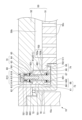
- FIG. 1 is an enlarged cross-sectional view showing the vicinity of the outer periphery of a showerhead having a connection assembly.
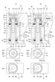
- 3A is a first enlarged view of the connection assembly when the cooling plate is not thermally expanded
- FIG 3B is a second enlarged view of the connection assembly when the cooling plate is thermally expanded.
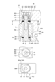
- FIG. 4 is a third enlarged view showing the connecting assembly in a state where the ceiling member has thermally expanded.
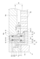
- FIG. 11 is an enlarged cross-sectional view showing the vicinity of the outer periphery of a shower head having a connection assembly according to a modified example.
- FIG. 6(A) is a first enlarged view showing a connection assembly according to a modified example when the cooling plate is not thermally expanded
- Fig. 6(B) is a second enlarged view showing a connection assembly according to a modified example when the cooling plate is thermally expanded.
- [Plasma Processing System] 1 is a diagram showing the overall configuration of a plasma processing system having a substrate processing apparatus (plasma processing apparatus 1) according to an embodiment of the present invention. First, an example of the configuration of the plasma processing system will be described with reference to FIG.
- the plasma processing system includes a capacitively coupled plasma processing device 1, which is a substrate processing device, and a control unit 2.
- the plasma processing device 1 includes a plasma processing chamber 10, a gas supply unit 20, a power supply 30, and an exhaust system 40.
- the plasma processing device 1 also includes a substrate support unit 11 and a gas introduction unit.
- the gas introduction unit is configured to introduce at least one processing gas into the plasma processing chamber 10.
- the gas introduction unit includes a shower head 50.
- the substrate support unit 11 is disposed in the plasma processing chamber 10.
- the shower head 50 is disposed above the substrate support unit 11. In one embodiment, the shower head 50 constitutes at least a part of the ceiling of the plasma processing chamber 10.
- the plasma processing chamber 10 has a plasma processing space 10s defined by the shower head 50, the sidewall 10a of the plasma processing chamber 10, and the substrate support unit 11.
- the plasma processing chamber 10 has at least one gas supply port for supplying at least one processing gas to the plasma processing space 10s and at least one gas exhaust port for exhausting gas from the plasma processing space.
- the sidewall 10a is grounded.
- the showerhead 50 and the substrate support 11 are electrically insulated from the plasma processing chamber 10 housing.
- the substrate support 11 includes a main body 111 and a ring assembly 112.
- the main body 111 has a central region (substrate support surface) 111a for supporting a substrate (wafer) W, and an annular region (ring support surface) 111b for supporting the ring assembly 112.
- the annular region 111b of the main body 111 surrounds the central region 111a of the main body 111 in a planar view.
- the substrate W is disposed on the central region 111a of the main body 111
- the ring assembly 112 is disposed on the annular region 111b of the main body 111 so as to surround the substrate W on the central region 111a of the main body 111.
- the main body 111 includes a base and an electrostatic chuck.
- the base includes a conductive member.
- the conductive member of the base functions as a lower electrode.
- the electrostatic chuck is disposed on the base.
- the upper surface of the electrostatic chuck has a substrate support surface 111a.
- the ring assembly 112 includes one or more annular members. At least one of the one or more annular members is an edge ring.
- the substrate support 11 may include a temperature adjustment module configured to adjust at least one of the electrostatic chuck, the ring assembly 112, and the substrate to a target temperature.
- the temperature adjustment module may include a heater, a heat transfer medium, a flow path, or a combination thereof.
- a heat transfer fluid such as brine or gas flows through the flow path.
- the substrate support 11 may also include a heat transfer gas supply unit configured to supply a heat transfer gas between the back surface of the substrate W and the substrate support surface 111a.
- the showerhead 50 is configured to introduce at least one processing gas from the gas supply unit 20 into the plasma processing space 10s.
- the showerhead 50 has at least one gas supply port 50a, at least one gas diffusion chamber 50b, and multiple gas inlets 50c.
- the processing gas supplied to the gas supply port 50a passes through the gas diffusion chamber 50b and is introduced into the plasma processing space 10s from the multiple gas inlets 50c.
- the showerhead 50 also includes a conductive member.
- the conductive member of the showerhead 50 functions as an upper electrode.
- the shower head 50 has a layered structure in which multiple components are stacked.
- the multiple components of the shower head 50 include a ceiling member (first member) 51 that forms the ceiling surface of the plasma processing space 10s, and a cooling plate (second member) 52 that is stacked on top of the ceiling member 51.
- the ceiling member 51 is formed in a disk shape and has multiple gas inlets 50c along the surface direction (horizontal direction).
- the ceiling member 51 according to the embodiment is configured as a conductive member (upper electrode) to which a source RF signal, a bias RF signal, etc. are supplied from a power source 30 described below.
- the ceiling member 51 generates plasma from the processing gas in the plasma processing space 10s by the supplied source RF signal, bias RF signal, etc. For this reason, the ceiling member 51 is formed from a material having conductivity.
- the material of the ceiling member 51 is not particularly limited, but examples include carbon (C: graphite, etc.), silicon (Si), silicon carbide (SiC), or a combination of these materials.
- the cooling plate 52 is formed in a disk shape with a recess, and is laminated on the upper surface of the ceiling member 51 to form a gas diffusion chamber 50b at the boundary with the ceiling member 51.
- the cooling plate 52 is also provided so as to be in close contact with the ceiling member 51, and has an internal cooling mechanism (not shown). As a result, heat from the ceiling member 51, which becomes hot due to the heat input from the plasma, is transferred to the cooling plate 52, thereby cooling the ceiling member 51.
- the cooling mechanism of the cooling plate 52 has, for example, a spiral or annular coolant flow path (not shown) extending in the circumferential direction.
- the cooling mechanism circulates the coolant by supplying and discharging a low-temperature coolant from a chiller unit provided outside the plasma processing chamber 10 to the coolant flow path of the cooling plate 52. Cooling water, Galden (registered trademark), or the like is used as the coolant.
- the cooling plate 52 is preferably formed of a material with high thermal conductivity in order to cool the ceiling member 51.
- the material of the cooling plate 52 is not particularly limited, but examples thereof include aluminum or aluminum alloys that have been anodized.
- the gas introduction section of the plasma processing chamber 10 may include one or more side gas injectors (SGIs) attached to one or more openings formed in the side wall 10a.
- SGIs side gas injectors
- the gas supply 20 may include at least one gas source 21 and at least one flow controller 22.
- the gas supply 20 is configured to supply at least one process gas from a respective gas source 21 through a respective flow controller 22 to the showerhead 50.
- Each flow controller 22 may include, for example, a mass flow controller or a pressure-controlled flow controller.
- the gas supply 20 may include one or more flow modulation devices to modulate or pulse the flow rate of the at least one process gas.
- the power supply 30 includes an RF power supply 31 coupled to the plasma processing chamber 10 via at least one impedance matching circuit.
- the RF power supply 31 is configured to supply at least one RF signal (RF power), such as a source RF signal and a bias RF signal, to the conductive member of the substrate support 11 and/or the conductive member of the showerhead 50. This causes a plasma to be formed from at least one processing gas supplied to the plasma processing space 10s.
- the RF power supply 31 can function as at least a part of a plasma generating unit configured to generate plasma from one or more processing gases in the plasma processing chamber 10.
- a bias RF signal to the conductive member of the substrate support 11
- a bias potential is generated on the substrate W, and ion components in the formed plasma can be attracted to the substrate W.
- the RF power supply 31 includes a first RF generating unit 31a and a second RF generating unit 31b.
- the first RF generating unit 31a is coupled to the conductive member of the substrate support 11 and/or the conductive member of the showerhead 50 via at least one impedance matching circuit and is configured to generate a source RF signal (source RF power) for plasma generation.
- the source RF signal has a frequency in the range of 13 MHz to 150 MHz.
- the first RF generating unit 31a may be configured to generate multiple source RF signals having different frequencies. The generated one or more source RF signals are supplied to the conductive member of the substrate support 11 and/or the conductive member of the showerhead 50.
- the second RF generating unit 31b is coupled to the conductive member of the substrate support 11 via at least one impedance matching circuit and is configured to generate a bias RF signal (bias RF power).
- the bias RF signal has a lower frequency than the source RF signal.
- the bias RF signal has a frequency in the range of 400 kHz to 13.56 MHz.
- the second RF generator 31b may be configured to generate multiple bias RF signals having different frequencies.
- the generated bias RF signal or signals are provided to the conductive members of the substrate support 11. Also, in various embodiments, at least one of the source RF signal and the bias RF signal may be pulsed.
- the power supply 30 may also include a DC power supply 32 coupled to the plasma processing chamber 10.
- the DC power supply 32 includes a first DC generator 32a and a second DC generator 32b.
- the first DC generator 32a is connected to a conductive member of the substrate support 11 and configured to generate a first DC signal.
- the generated first bias DC signal is applied to the conductive member of the substrate support 11.
- the first DC signal may be applied to another electrode, such as an electrode in an electrostatic chuck.
- the second DC generator 32b is connected to a conductive member of the showerhead 50 and configured to generate a second DC signal.
- the generated second DC signal is applied to the conductive member of the showerhead 50.
- at least one of the first and second DC signals may be pulsed.
- the first and second DC generating units 32a and 32b may be provided in addition to the RF power source 31, or the first DC generating unit 32a may be provided in place of the second RF generating unit 31b.
- the exhaust system 40 may be connected to, for example, a gas exhaust port 10e provided at the bottom of the plasma processing chamber 10.
- the exhaust system 40 may include a pressure regulating valve and a vacuum pump. The pressure in the plasma processing space 10s is adjusted by the pressure regulating valve.
- the vacuum pump may include a turbomolecular pump, a dry pump, or a combination thereof.
- the control unit 2 processes computer-executable instructions that cause the plasma processing apparatus 1 to perform the various steps described in this disclosure.
- the control unit 2 may be configured to control each element of the plasma processing apparatus 1 to perform the various steps described herein. In one embodiment, a part or all of the control unit 2 may be included in the plasma processing apparatus 1.
- the control unit 2 may include, for example, a computer 2a.
- the computer 2a may include, for example, a processing unit (CPU: Central Processing Unit) 2a1, a memory unit 2a2, and a communication interface 2a3.
- the processing unit 2a1 may be configured to perform various control operations based on a program stored in the memory unit 2a2.
- the memory unit 2a2 may include a RAM (Random Access Memory), a ROM (Read Only Memory), a HDD (Hard Disk Drive), an SSD (Solid State Drive), or a combination thereof.
- the communication interface 2a3 may communicate with the plasma processing device 1 via a communication line such as a LAN (Local Area Network).
- FIG. 2 is an enlarged cross-sectional view showing the vicinity of the outer periphery of the showerhead 50 having the connection assembly 60.
- the showerhead 50 of the plasma processing apparatus 1 is installed on the upper part of the plasma processing chamber 10 in a state in which the above-mentioned multiple members (ceiling member 51, cooling plate 52) are stacked.
- the showerhead 50 includes multiple connection assemblies 60 that connect the ceiling member 51 and the cooling plate 52 to the outer periphery of the ceiling member 51 and the cooling plate 52.
- the ceiling member 51 and the cooling plate 52 are formed from different materials as described above. Therefore, the thermal expansion coefficients of the ceiling member 51 and the cooling plate 52 are also different.
- the connecting assembly 60 has a clamping function that clamps and connects the ceiling member 51 and the cooling plate 52 in the up-down direction (vertical direction).
- the shower head 50 may be configured by stacking other members in addition to the ceiling member 51 and the cooling plate 52.
- the connecting assembly 60 is not limited to one that clamps two members, but may be configured to clamp three or more members.
- the ceiling member 51 of the shower head 50 has an attachment step 511 that can be hooked onto the connecting assembly 60 on the outer periphery radially outward of the discharge surface having the multiple gas inlets 50c.
- the attachment step 511 of the ceiling member 51 is formed to be thinner than the thickness of the discharge surface portion, and has a circular ring shape that goes around the ceiling member 51.
- the cooling plate 52 of the shower head 50 has a protruding outer periphery 521 that protrudes radially outward from the main body portion that contacts the ceiling member 51.
- This protruding outer periphery 521 is formed in an annular shape and is located radially outward from the mounting step 511 of the ceiling member 51.
- An accommodation hole 522 that accommodates a part (upper part) of the connecting assembly 60 is provided in an adjacent position on the radial outside of the protruding outer periphery 521 of the ceiling member 51.
- the accommodation holes 522 are provided in a number corresponding to the number of connecting assemblies 60 to be installed, and are arranged at intervals in the circumferential direction of the protruding outer periphery 521.
- the multiple connecting assemblies 60 have a portion that engages with the mounting step 511 of the ceiling member 51 and a portion that is inserted into the accommodation hole 522 and engages with the cooling plate 52, and clamp the ceiling member 51 and the cooling plate 52. Each connecting assembly 60 clamps the ceiling member 51 and the cooling plate 52 at multiple points around the circumference, thereby maintaining the ceiling member 51 and the cooling plate 52 in a sealed state.
- the showerhead 50 may also have an O-ring (not shown) or the like at the boundary between the ceiling member 51 and the cooling plate 52 to hermetically seal both members.
- Each connection assembly 60 includes a male screw member 61, a disc spring 62, an elastic receiving member 63, an upper sliding seat member 64, a locking member 65, a female screw member 66, a washer 67, a lower sliding seat member 68, a guide member 69, and a female screw holder 70.
- the plasma processing chamber 10 also has a protective case 71 that covers the female screw holder 70, and an insulating member 72 that sandwiches the protective case 71 between the cooling plate 52.
- the male screw member 61 is a member whose upper portion is accommodated in the accommodation hole 522 of the cooling plate 52, while its lower portion exposed from the accommodation hole 522 is inserted into the female screw member 66.
- the male screw member 61 and the female screw member 66 extend parallel to the stacking direction of the ceiling member 51 and the cooling plate 52, and form a fastening structure 73 that screws together.
- the connecting assembly 60 can adjust the clamping force on the ceiling member 51 and the cooling plate 52 by adjusting the axial length of the screwed male screw member 61 and the female screw member 66.
- the male screw member 61 has a lower screw portion 611 having a thread 61a on its outer circumferential surface that screws into the female screw member 66, an intermediate rod portion 612 connected to the upper end of the lower screw portion 611, and a head portion 613 provided at the upper end of the intermediate rod portion 612.
- the head portion 613 also includes a flange 614 that protrudes radially outward from the intermediate rod portion 612, a connecting member 615 provided at the axis of the intermediate rod portion 612, and a heat insulating member 616 connected to the connecting member 615.
- the lower screw portion 611, the intermediate rod portion 612, and the flange 614 are integrally molded with each other.
- the lower region of the lower screw portion 611 is inserted into the female screw hole 663 of the female screw member 66, and is directly screwed into the female screw member 66.
- the intermediate rod portion 612 has a smooth outer peripheral surface, and the disc spring 62 is arranged around its side.
- the flange 614 is formed in an annular shape in a plan view, and functions as a seat that receives the elastic force of the disc spring 62.
- the connecting member 615 is housed in a T-shaped hole in a cross-sectional view formed at the axis of the intermediate rod portion 612, and protrudes slightly vertically upward from the intermediate rod portion 612.
- the insulating member 616 covers the protruding connecting member 615 and is fixed to the connecting member 615, thereby suppressing the transfer of temperature from the cooling plate 52 to the male screw member 61.
- the coned disc spring 62 is disposed between the flange 614 of the male screw member 61 and the elastic receiving member 63, and has the function of elastically receiving the load applied to both members (load parallel to the stacking direction).
- the connecting assembly 60 has multiple (five) coned disc springs 62 stacked vertically, and can mitigate large loads applied in the vertical direction.
- the coned disc spring 62 can move integrally with the male screw member 61 by contacting the outer circumferential surface of the intermediate rod portion 612 of the male screw member 61.
- the elastic receiving member 63 is a cylindrical member arranged around the male screw member 61, with one end of the disc spring 62 in contact with its upper end surface.
- the outer circumferential surface of the elastic receiving member 63 is formed with an outer diameter slightly larger than the outer diameter of the flange 614 of the male screw member 61 and the outer diameter of the disc spring 62.
- the elastic receiving member 63 is formed with an outer diameter in the range of about 2/3 to 9/10 of the inner diameter of the accommodation hole 522. This creates an appropriate gap C1 between the outer circumferential surface of the elastic receiving member 63 and the inner circumferential surface of the accommodation hole 522 (see FIG. 3A).
- the gap C1 allows the male screw member 61, the disc spring 62, and the elastic receiving member 63 to slide horizontally (in a direction perpendicular to the stacking direction of the ceiling member 51 and the cooling plate 52).
- the lower end surface of the elastic receiving member 63 is a flat (smooth) sliding surface 631 that extends horizontally and is in contact with the upper sliding seat member 64.
- the sliding surface 631 allows the elastic receiving member 63 to slide relative to the upper sliding seat member 64.
- the upper sliding seat member 64 is formed in a circular ring shape with its underside supported by the locking member 65, and is a member that supports the above-mentioned elastic receiving member 63 so that it can move relative to the elastic receiving member 63.
- the connecting assembly 60 by using the elastic receiving member 63 and the upper sliding seat member 64, forms a sliding structure 74 that can slide in the horizontal direction perpendicular to the stacking direction.
- the outer diameter of the upper sliding seat member 64 roughly matches the inner diameter of the accommodation hole 522. As a result, the upper sliding seat member 64 maintains a state in which horizontal sliding within the accommodation hole 522 is restricted.
- the upper surface of the upper sliding seat member 64 is a flat (smooth) sliding surface 641 extending horizontally.
- the sliding structure 74 is not limited to the sliding surface 631 of the elastic receiving member 63 and the sliding surface 641 of the upper sliding seat member 64 described above, and can have various configurations.
- the sliding structure 74 may be a sliding bearing applied to either the elastic receiving member 63 or the upper sliding seat member 64, the sliding bearing having multiple rolling elements that are in contact with the sliding surface of the other and can roll.
- the locking member 65 is formed in a circular ring shape in a plan view, and is fitted into an engagement groove formed on the inner circumferential surface of the accommodation hole 522.
- This locking member 65 is fixed in an undetachable manner to the cooling plate 52, and is therefore able to stably support the upper sliding seat member 64.
- the male screw member 61, disc spring 62, elastic receiving member 63, and upper sliding seat member 64 are prevented from falling out of the accommodation hole 522 by the locking member 65, and it is also possible to elastically support the male screw member 61 along the vertical direction.
- the female screw member 66 is a member that screws into the male screw member 61 in the connecting assembly 60, and is formed to be thicker than the male screw member 61.
- This female screw member 66 has a female screw body 661 that extends vertically, and a flange head 662 that is connected to the lower end of the female screw body 661.
- the female screw body 661 and the flange head 662 are molded integrally with each other.
- the female screw body 661 extends linearly in the vertical direction and is longer than the lower screw engagement portion 611 of the male screw member 61.
- An opening for a female screw hole 663 is provided at the upper end of the female screw body 661.
- the female screw hole 663 is formed vertically downward from the opening to a predetermined depth, and its inner peripheral surface is formed with a screw groove (not shown) into which the thread 61a of the male screw member 61 can be screwed.
- a rotation hole portion 664 is provided at the lower end surface of the female screw body 661 for inserting a wrench (such as a hexagonal wrench) (not shown) to rotate the female screw member 66 (see FIG. 3(A)).
- the flange head 662 protrudes a short distance radially outward from the lower end of the female screw body 661.
- a washer 67 is layered on the upper surface of this flange head 662.
- the washer 67 is formed in an annular shape, is supported by the flange head 662, and protrudes radially outward beyond the outer circumferential surface of the flange head 662.
- the lower sliding seat member 68 is formed in an annular shape, supported by a washer 67, and fitted onto the outer circumferential surface of the female screw body 661.
- the inner diameter of the lower sliding seat member 68 roughly matches the outer diameter of the female screw body 661. This allows the lower sliding seat member 68 to move integrally with the female screw member 66.
- the lower sliding seat member 68 like the upper sliding seat member 64, slidably supports the guide member 69 that is stacked on its upper surface.
- the upper surface of the lower sliding seat member 68 is a flat (smooth) sliding surface 681 extending horizontally.
- the sliding structure 74 of the lower sliding seat member 68 and the guide member 69 is not limited to this, and for example, a sliding bearing having multiple rolling elements may be applied to either the lower sliding seat member 68 or the guide member 69.
- the guide member 69 is supported by the lower sliding seat member 68 and is fitted to the outer circumferential surface of the female screw body 661.
- the inner diameter of the guide member 69 is larger than the outer diameter of the female screw body 661, and a gap C2 is created between the inner circumferential surface of the guide member 69 and the outer circumferential surface of the female screw body 661. This gap C2 allows the female screw holder 70 to slide horizontally relative to the female screw body 661.
- the guide member 69 is formed in a D-shape in a plan view, and is inserted into the through-hole 703 (lower hole 703b) of the female screw holder 70, which is also formed in a D-shape (see also FIG. 3(A)). This allows the guide member 69 to align the female screw holder 70 in a fixed direction.
- the female screw holder 70 is arranged to face the accommodation hole 522 of the cooling plate 52, and is configured as a square tube-shaped member that covers the side periphery of the female screw member 66 and hooks onto the mounting step 511 of the ceiling member 51.
- the female screw holder 70 has a holder portion 701 that extends vertically to a length approximately equal to that of the female screw member 66, and an engagement protrusion 702 that protrudes from the lower side of the holder portion 701 toward the ceiling member 51.
- a through hole 703 for placing the female screw member 66 is formed inside the holder portion 701.
- the through hole 703 includes an upper hole 703a in which the female screw body 661 is placed at the top, and a lower hole 703b in which the flange head 662, washer 67, lower sliding seat member 68, and guide member 69 are placed below the upper hole 703a.
- the inner diameter of the upper hole 703a is formed larger than the outer diameter of the female screw body 661 of the female screw member 66, forming a gap C2.
- the lower hole 703b is formed in a D-shape and houses the guide member 69.
- the engaging protrusion 702 protrudes toward the ceiling member 51, and its upper surface contacts the mounting step 511 of the ceiling member 51.
- the connecting assembly 60 adjusts the axial length of the male screw member 61 and the female screw member 66 by screwing them together, so that the engaging protrusion 702 comes into contact with the mounting step 511 and can clamp the ceiling member 51.
- the connecting assembly 60 sandwiches the ceiling member 51 and the cooling plate 52 between the locking member 65 connected to the cooling plate 52 and the female screw holder 70 that engages with the ceiling member 51.
- the protective case 71 also extends from the sidewall 10a of the plasma processing chamber 10 to the ceiling member 51 of the shower head 50, covering the above-mentioned connection assembly 60 and preventing the connection assembly 60 from being exposed to the plasma processing space 10s.
- the insulating member 72 is provided between the sidewall 10a of the plasma processing chamber 10 and the shower head 50 (including the connecting assembly 60), thereby insulating the ceiling member 51, which functions as an upper electrode, from the sidewall 10a. This allows the plasma processing apparatus 1 to stably generate plasma in the plasma processing space 10s based on a signal supplied from the power source 30 to the ceiling member 51.
- the plasma processing apparatus 1 is basically configured as described above, and its operation will be described below.
- the plasma processing apparatus 1 supplies processing gas to the plasma processing space 10s of the plasma processing chamber 10 through the shower head 50.
- the plasma processing apparatus 1 also supplies a source RF signal or a bias RF signal from the power supply 30 to the shower head 50 to generate plasma in the plasma processing space 10s.
- the shower head 50 receives heat from the plasma generated in the plasma processing space 10s.
- the ceiling member 51 and the cooling plate 52 of the shower head 50 are made of materials with different thermal expansion coefficients. Therefore, a difference in thermal expansion occurs between the ceiling member 51 and the cooling plate 52 when the heat of the plasma is input.
- the plasma processing apparatus 1 uses a connection assembly 60 to connect the ceiling member 51 and the cooling plate 52, as described above.
- Fig. 3(A) is a first enlarged view showing the connecting assembly 60 when the cooling plate 52 is not thermally expanded.
- Fig. 3(B) is a second enlarged view showing the connecting assembly 60 when the cooling plate 52 is thermally expanded.
- Fig. 4 is a third enlarged view showing the connecting assembly 60 when the ceiling member 51 is thermally expanded.
- the middle view shows a cross-sectional view along line A-A in the upper view, and the lower view shows a view in the direction of arrow B in the upper view.
- the connecting assembly 60 forms a gap C1 between the inner circumferential surface of the accommodation hole 522 of the cooling plate 52 and the male screw member 61, the disc spring 62, and the elastic receiving member 63.
- This gap C1 allows the connecting assembly 60 to allow relative movement of the male screw member 61, the disc spring 62, the elastic receiving member 63, etc. with respect to the upper sliding seat member 64 (and the locking member 65).
- the connecting assembly 60 forms a gap C2 between the female screw member 66, washer 67, and lower sliding seat member 68 and the guide member 69 and the inner circumferential surface of the through hole 703 of the female screw holder 70.
- This gap C2 allows the connecting assembly 60 to move the guide member 69 and the female screw holder 70 relative to the lower sliding seat member 68.
- the male screw member 61 and the female screw member 66 are screwed together to firmly clamp the ceiling member 51 and the cooling plate 52.
- the male screw member 61 accommodated in the accommodation hole 522 is hooked onto the cooling plate 52 via the flange 614, the disc spring 62, the elastic receiving member 63, the upper sliding seat member 64, and the locking member 65.
- the connecting assembly 60 applies a force that pushes the cooling plate 52 downward in the vertical direction.
- the female screw member 66 is hooked onto the mounting step portion 511 of the ceiling member 51 via the flange head 662, the washer 67, the lower sliding seat member 68, the guide member 69, and the female screw holder 70.
- the connecting assembly 60 applies a force that pushes the ceiling member 51 upward in the vertical direction. Therefore, the connection assembly 60 can firmly clamp the ceiling member 51 and the cooling plate 52, bringing the two members into close contact. Even if the plasma in the plasma processing space 10s inputs heat to the ceiling member 51 during plasma processing, the shower head 50 can smoothly dissipate the heat from the ceiling member 51 to the cooling plate 52.
- the elastic receiving member 63 which is in contact with the sliding surface 641 of the upper sliding seat member 64 via the sliding surface 631, does not follow the sliding of the upper sliding seat member 64 because the sliding surfaces 631, 641 slide horizontally against each other. This causes the upper sliding seat member 64 to slide relative to the elastic receiving member 63. As a result, the connecting assembly 60 moves the locking member 65 and the upper sliding seat member 64 horizontally outward in response to thermal expansion of the cooling plate 52, while maintaining the positions of the elastic receiving member 63, disc spring 62, male screw member 61, etc. Therefore, the inside of the gap C1 (towards the center of the cooling plate 52) becomes smaller.
- the male screw member 61 is not displaced even by the thermal expansion of the cooling plate 52, and can maintain good screw engagement with the female screw member 66.
- the connecting assembly 60 can prevent the stress of the thermal expansion of the cooling plate 52 from being applied to the fastening structure 73, making it possible to avoid damage to the connecting assembly 60, the ceiling member 51, or the cooling plate 52, etc.
- the ceiling member 51 thermally expands relative to the cooling plate 52.
- the ceiling member 51 may thermally expand.
- the mounting step portion 511 also moves radially outward.
- the female screw holder 70 engaged with the mounting step portion 511 also slides horizontally (radially outward from the ceiling member 51).
- the guide member 69 of the female screw holder 70 moves relative to the lower sliding seat member 68 because the sliding surface 691 contacts the sliding surface 681 of the lower sliding seat member 68.
- the female screw member 66, washer 67, and lower sliding seat member 68 do not follow the sliding of the female screw holder 70 or guide member 69.
- the connecting assembly 60 can accommodate the thermal expansion of the ceiling member 51 while reducing the inside of the gap C2 (the side toward the center of the ceiling member 51).
- the female screw member 66 is not displaced even by the thermal expansion of the ceiling member 51, and can maintain good screw engagement with the male screw member 61.
- the connecting assembly 60 can prevent the stress of the thermal expansion of the ceiling member 51 from being applied to the fastening structure 73, and can avoid damage to the connecting assembly 60, the ceiling member 51, or the cooling plate 52, etc.
- the connecting assembly 60 has a sliding structure 74, which allows it to stably connect components with different thermal expansion coefficients. Furthermore, the connecting assembly 60 has sliding structures 74 at multiple locations (locations corresponding to the male threaded member 61 and locations corresponding to the female threaded member 66), which allows it to appropriately accommodate thermal expansion depending on the location of the component with large thermal expansion. Furthermore, the multiple sliding structures 74 can accommodate thermal expansion even when there is a large difference in thermal expansion.
- the connecting assembly 60 can firmly attach the ceiling member 51 and the cooling plate 52 by adjusting the axial length of the screwed male screw member 61 and the female screw member 66. Furthermore, the connecting assembly 60 has a sliding structure 74 outside the outer circumferential surface of the fastening structure 73 (male screw member 61, female screw member 66), so that the sliding structure 74 can slide appropriately while maintaining the screwed fastening structure 73.
- the sliding structure 74 is disposed adjacent to the female screw member 66, so that it can easily absorb the shear force applied to the female screw member 66 during thermal expansion.
- the sliding structure 74 is disposed adjacent to the male screw member 61, so that it can easily absorb the shear force applied to the male screw member 61 during thermal expansion.
- the sliding structure 74 has two sliding surfaces 631, 641 (or sliding surfaces 681, 691) in contact with each other, and thus can perform sliding in a direction perpendicular to the stacking direction with a simple configuration. Alternatively, when a member having a rolling body that contacts the sliding surface is used, the sliding structure 74 can perform even smoother sliding.
- connection assembly 60 connects the ceiling member 51 and the cooling plate 52 of the shower head 50.
- the connection assembly 60 may connect other members in the plasma processing chamber 10.
- the other members include the substrate support 11, a baffle plate attached to the plasma processing chamber 10, a shielding member, etc.
- the connection assembly 60 may be used as a connection part that connects the plasma processing chambers 10.
- the connection assembly 60 may be applied to a substrate processing apparatus that performs a heat treatment without performing a plasma treatment.
- connection assembly 60 the male thread member 61 is disposed on the cooling plate 52 side, and the female thread member 66 is disposed on the ceiling member 51 side.
- this arrangement may be reversed.
- the connecting assembly 60 is configured to engage the engaging protrusion 702 of the female screw holder 70 with the mounting step 511 of the ceiling member 51.
- the ceiling member 51 has a hole with a similar configuration to the through hole 703 described above, the ceiling member 51 can be fastened with the female screw member 66 without using the female screw holder 70.
- a washer 67, a lower sliding seat member 68, a guide member 69, etc. may be interposed between the female screw member 66 and the ceiling member 51.
- FIG. 5 is an enlarged cross-sectional view showing the vicinity of the outer periphery of the shower head 50 having the connection assembly 60A according to the modified example.
- Fig. 6(A) is a first enlarged view showing the connection assembly 60A according to the modified example in a state in which the cooling plate 52 is not thermally expanded.
- Fig. 6(B) is a second enlarged view showing the connection assembly 60A according to the modified example in a state in which the cooling plate 52 is thermally expanded.
- the lower diagrams of Figs. 6(A) and 6(B) show views in the direction of the arrow B in the upper diagrams.
- the modified connecting assembly 60A differs from the connecting assembly 60 in that it has a sliding structure 74 adjacent to the female threaded member 66 (between the female threaded member 66 and the female threaded holder 70), but does not have a sliding structure 74 adjacent to the male threaded member 61.
- connection assembly 60A includes a male screw member 61, a disc spring 62, an elastic receiving member 63, a locking member 65, a female screw member 66, a washer 67, a lower sliding seat member 68, a guide member 69, and a female screw holder 70.
- the female screw member 66 is inserted into the elastic receiving member 63 while being screwed into the male screw member 61 and placed in the receiving hole 522.
- the male screw member 61 has a lower screw-in portion 611, an intermediate rod portion 612, and a head portion 613.
- the disc spring 62 has one end in contact with the head portion 613, which protrudes radially outward, and is fitted to the outer circumferential surface of the intermediate rod portion 612.
- the elastic receiving member 63 is formed in a cylindrical shape extending along the vertical direction, and is supported by a locking member 65 fitted into the accommodation hole 522 at its vertically lower side.
- the elastic receiving member 63 has a hole portion 63h into which the female screw member 66 can be inserted from the vertically lower side.
- the outer diameter of the elastic receiving member 63 is approximately the same as the inner diameter of the accommodation hole 522, and is configured so that there is no gap C1 (see Figure 3 (A)) between it and the cooling plate 52.
- the elastic receiving member 63 and the female screw member 66 also move horizontally in response to the thermal expansion.
- the female screw member 66 has a female screw body 661 and a flange head 662, and the upper end of the female screw body 661 is inserted into the elastic receiving member 63 and accommodated in the accommodation hole 522.
- the washer 67 is supported by the flange head 662 of this female screw member 66.
- the lower sliding seat member 68 is formed in an annular shape and has a sliding surface 681 on its upper surface.
- the guide member 69 has a sliding surface 691 on its lower surface that contacts the lower sliding seat member 68.
- the connecting assembly 60A forms a single sliding structure 74 by the lower sliding seat member 68 and the guide member 69.
- the guide member 69 is fixed to the female screw holder 70.
- the female screw holder 70 has a holder portion 701 and an engaging protrusion 702, and the engaging protrusion 702 engages with the mounting step portion 511 of the ceiling member 51.
- the through hole 703 of the female screw holder 70 has an upper hole 703a and a lower hole 703b, and forms a gap C2 between the female screw member 66. Furthermore, the lower hole 703b of the through hole 703 is formed as an elongated hole that moves the flange head 662 of the female screw member 66 in one direction.
- the modified connecting assembly 60 is basically formed as described above, and its function will be explained below.
- the connecting assembly 60A firmly clamps the ceiling member 51 and the cooling plate 52 by screwing together the male screw member 61 and the female screw member 66.
- the male screw member 61 is hooked onto the cooling plate 52 via the flange 614, the disc spring 62, the elastic receiving member 63, and the locking member 65, thereby pushing the cooling plate 52 downward in the vertical direction.
- the female screw member 66 is hooked onto the flange head 662, the washer 67, the lower sliding seat member 68, the guide member 69, and the female screw holder 70 at the protruding outer periphery 521, thereby pushing the ceiling member 51 upward in the vertical direction. Therefore, the connecting assembly 60A makes it possible to bring the ceiling member 51 and the cooling plate 52 into close contact with each other.
- the connecting assembly 60A forms a gap C2 between the outer peripheral surface of the female screw member 66 (female screw body 661, flange head 662) and the inner peripheral surface of the through hole 703 of the guide member 69 and the female screw holder 70.
- the horizontal sliding of the female screw member 66 also causes the washer 67 and the lower sliding seat member 68 to slide.
- the guide member 69 which is in contact with the sliding surface 681 of the lower sliding seat member 68 via the sliding surface 691, does not follow the sliding of the lower sliding seat member 68. This causes the lower sliding seat member 68 to move relative to the guide member 69.
- the connecting assembly 60A can accommodate the thermal expansion of the cooling plate 52 while reducing the outer side of the gap C2 (the side away from the cooling plate 52).
- the female screw member 66 can be maintained in a state where it is not displaced even by the thermal expansion of the cooling plate 52. This prevents the stress of the thermal expansion of the cooling plate 52 from being exerted on the fastening structure 73, and prevents damage to the connecting assembly 60A, the ceiling member 51, or the cooling plate 52.
- the modified connecting assembly 60A can also effectively connect two components with different thermal expansion coefficients, and can tolerate the difference in thermal expansion of multiple components.
- the connecting assembly 60A with a single sliding structure 74, the structure can be further simplified, making it possible to reduce manufacturing costs.
- the connection assembly has a sliding structure that is slidable in a direction perpendicular to the stacking direction when the first member and/or the second member undergo thermal expansion.
- Substrate processing equipment [Appendix 2]
- the connection assembly has a male screw member and a female screw member that extend in the stacking direction and screw together, a clamping force for the first member and the second member is adjusted by adjusting an axial length of the male screw member and the female screw member in the screwed engagement; 2.
- the substrate processing apparatus of claim 1 [Appendix 3] The sliding structure is provided outside the outer circumferential surface of the male thread member and the outer circumferential surface of the female thread member. 3. The substrate processing apparatus of claim 2. [Appendix 4] The sliding structure is disposed adjacent to the female screw member. 4. The substrate processing apparatus according to claim 2 or 3. [Appendix 5] The sliding structure is disposed adjacent to the male screw member exposed from the female screw member. 5. The substrate processing apparatus according to claim 2 . [Appendix 6] The connecting assembly has a plurality of the sliding structures along the stacking direction. 6. The substrate processing apparatus according to claim 1 .
- the sliding structure has sliding surfaces of two members each having a sliding surface extending in a direction perpendicular to the stacking direction, the sliding surfaces being in contact with each other. 7.
- the substrate processing apparatus according to claim 1 [Appendix 8]
- the sliding structure is configured to contact a member having a sliding surface extending in a direction perpendicular to the stacking direction with a member having a rolling element in contact with the sliding surface. 8.
- the first member and the second member are provided in a plasma processing chamber having a plasma processing space therein for generating plasma. 9. The substrate processing apparatus according to claim 1 .
- the first member and the second member constitute a showerhead that discharges a processing gas inside the plasma processing chamber and receives power for generating the plasma; 10.
- the first member is a ceiling member having a plurality of gas inlets through which the processing gas is introduced into the plasma processing space,
- the second member is a cooling plate that is provided vertically above the first member and dissipates heat from the ceiling member. 11.
- connection assembly for connecting a first member and a second member provided in a substrate processing apparatus for processing a substrate, the connection assembly comprising: the first member and the second member are laminated on each other and have different thermal expansion coefficients;
- the connection assembly includes: a sliding structure extending parallel to a stacking direction of the first member and the second member and capable of sliding in a direction perpendicular to the stacking direction when the first member and/or the second member is thermally expanded; Linkage assembly.
- the substrate processing apparatus and connection assemblies 60, 60A are illustrative in all respects and not restrictive.
- the embodiments may be modified and improved in various ways without departing from the spirit and scope of the appended claims.
- the matters described in the above embodiments may be configured in other ways as long as they are not inconsistent, and may be combined as long as they are not inconsistent.
- the substrate processing apparatus disclosed herein can be applied to any type of apparatus, including Atomic Layer Deposition (ALD) apparatus, Capacitively Coupled Plasma (CCP), Inductively Coupled Plasma (ICP), Radial Line Slot Antenna (RLSA), Electron Cyclotron Resonance Plasma (ECR), and Helicon Wave Plasma (HWP).
- ALD Atomic Layer Deposition
- CCP Capacitively Coupled Plasma
- ICP Inductively Coupled Plasma
- RLSA Radial Line Slot Antenna
- ECR Electron Cyclotron Resonance Plasma
- HWP Helicon Wave Plasma
Landscapes
- Physics & Mathematics (AREA)
- Engineering & Computer Science (AREA)
- Plasma & Fusion (AREA)
- Electromagnetism (AREA)
- Spectroscopy & Molecular Physics (AREA)
- Container, Conveyance, Adherence, Positioning, Of Wafer (AREA)
Abstract
Description
図1は、実施形態に係る基板処理装置(プラズマ処理装置1)を有するプラズマ処理システムの全体構成を示す図である。まず図1を参照しながら、プラズマ処理システムの構成例について説明する。
図2は、連結アセンブリ60を有するシャワーヘッド50の外周部付近を拡大して示す断面図である。図2に示すように、プラズマ処理装置1シャワーヘッド50は、上記した複数の部材(天井部材51、クーリングプレート52)を積層した状態として、プラズマ処理チャンバ10の上部に設置する。このため、シャワーヘッド50は、天井部材51およびクーリングプレート52の外周部に、天井部材51およびクーリングプレート52を連結する複数の連結アセンブリ60を備える。
実施形態に係るプラズマ処理装置1は、基本的には以上のように構成され、以下その作用について説明する。
次に、変形例に係る連結アセンブリ60Aについて、図5および図6を参照しながら説明する。図5は、変形例に係る連結アセンブリ60Aを有するシャワーヘッド50の外周部付近を拡大して示す断面図である。図6(A)は、クーリングプレート52が熱膨張していない状態の変形例に係る連結アセンブリ60Aを示す第1拡大図である。図6(B)は、クーリングプレート52が熱膨張した状態の変形例に係る連結アセンブリ60Aを示す第2拡大図である。なお、図6(A)および図6(B)の下図は、上図の矢印B方向の矢視図を示している。
基板を処理する基板処理装置であって、
相互に積層され、かつ相互に異なる熱膨張係数を有する第1部材および第2部材と、
前記第1部材および前記第2部材の積層方向に平行して延在し、前記第1部材と前記第2部材を連結する連結アセンブリと、を備え、
前記連結アセンブリは、前記第1部材および/または前記第2部材の熱膨張時に、前記積層方向と直交する方向にスライド可能なすべり構造を有する、
基板処理装置。
[付記2]
前記連結アセンブリは、前記積層方向に延在して相互に螺合する雄ネジ部材および雌ネジ部材を有し、
前記雄ネジ部材および前記雌ネジ部材の螺合における軸方向の長さを調整することで、前記第1部材および前記第2部材に対するクランプ力を調整する、
付記1に記載の基板処理装置。
[付記3]
前記すべり構造は、前記雄ネジ部材の外周面および前記雌ネジ部材の外周面よりも外側に設けられる、
付記2に記載の基板処理装置。
[付記4]
前記すべり構造は、前記雌ネジ部材の隣接位置に配置される、
付記2または3に記載の基板処理装置。
[付記5]
前記すべり構造は、前記雌ネジ部材から露出している前記雄ネジ部材の隣接位置に配置される、
付記2乃至4のいずれか1項に記載の基板処理装置。
[付記6]
前記連結アセンブリは、前記積層方向に沿って前記すべり構造を複数有する、
付記1乃至5のいずれか1項に記載の基板処理装置。
[付記7]
前記すべり構造は、前記積層方向と直交する方向に延在するすべり面を有する2つの部材の当該すべり面同士を接触させている、
付記1乃至6のいずれか1項に記載の基板処理装置。
[付記8]
前記すべり構造は、前記積層方向と直交する方向に延在するすべり面を有する部材と、前記すべり面に接触する転動体を有する部材とを接触させている、
付記1乃至7のいずれか1項に記載の基板処理装置。
[付記9]
前記第1部材および前記第2部材は、プラズマを生成するプラズマ処理空間を内部に有するプラズマ処理チャンバに設けられる、
付記1乃至8のいずれか1項に記載の基板処理装置。
[付記10]
前記第1部材および前記第2部材は、前記プラズマ処理チャンバの内部において処理ガスを吐出すると共に、前記プラズマを生成するための電力が供給されるシャワーヘッドを構成している、
付記9に記載の基板処理装置。
[付記11]
前記第1部材は、前記プラズマ処理空間に前記処理ガスを導入する複数のガス導入口を有する天井部材であり、
前記第2部材は、前記第1部材よりも鉛直方向上側に設けられ、前記天井部材の熱を放熱するクーリングプレートである、
付記10に記載の基板処理装置。
[付記12]
基板を処理する基板処理装置に設けられる第1部材および第2部材を連結する連結アセンブリであって、
前記第1部材および前記第2部材は、相互に積層され、かつ相互に異なる熱膨張係数を有するものであり、
前記連結アセンブリは、
前記第1部材および前記第2部材の積層方向に平行して延在し、前記第1部材および/または前記第2部材の熱膨張時に、前記積層方向と直交する方向にスライド可能なすべり構造を有する、
連結アセンブリ。
51 天井部材
52 クーリングプレート
60、60A 連結アセンブリ
74 すべり構造
W 基板
Claims (12)
- 基板を処理する基板処理装置であって、
相互に積層され、かつ相互に異なる熱膨張係数を有する第1部材および第2部材と、
前記第1部材および前記第2部材の積層方向に平行して延在し、前記第1部材と前記第2部材を連結する連結アセンブリと、を備え、
前記連結アセンブリは、前記第1部材および/または前記第2部材の熱膨張時に、前記積層方向と直交する方向にスライド可能なすべり構造を有する、
基板処理装置。 - 前記連結アセンブリは、前記積層方向に延在して相互に螺合する雄ネジ部材および雌ネジ部材を有し、
前記雄ネジ部材および前記雌ネジ部材の螺合における軸方向の長さを調整することで、前記第1部材および前記第2部材に対するクランプ力を調整する、
請求項1に記載の基板処理装置。 - 前記すべり構造は、前記雄ネジ部材の外周面および前記雌ネジ部材の外周面よりも外側に設けられる、
請求項2に記載の基板処理装置。 - 前記すべり構造は、前記雌ネジ部材の隣接位置に配置される、
請求項2に記載の基板処理装置。 - 前記すべり構造は、前記雌ネジ部材から露出している前記雄ネジ部材の隣接位置に配置される、
請求項2に記載の基板処理装置。 - 前記連結アセンブリは、前記積層方向に沿って前記すべり構造を複数有する、
請求項1乃至5のいずれか1項に記載の基板処理装置。 - 前記すべり構造は、前記積層方向と直交する方向に延在するすべり面を有する2つの部材の当該すべり面同士を接触させている、
請求項1乃至5のいずれか1項に記載の基板処理装置。 - 前記すべり構造は、前記積層方向と直交する方向に延在するすべり面を有する部材と、前記すべり面に接触する転動体を有する部材とを接触させている、
請求項1乃至5のいずれか1項に記載の基板処理装置。 - 前記第1部材および前記第2部材は、プラズマを生成するプラズマ処理空間を内部に有するプラズマ処理チャンバに設けられる、
請求項1乃至5のいずれか1項に記載の基板処理装置。 - 前記第1部材および前記第2部材は、前記プラズマ処理チャンバの内部において処理ガスを吐出すると共に、前記プラズマを生成するための電力が供給されるシャワーヘッドを構成している、
請求項9に記載の基板処理装置。 - 前記第1部材は、前記プラズマ処理空間に前記処理ガスを導入する複数のガス導入口を有する天井部材であり、
前記第2部材は、前記第1部材よりも鉛直方向上側に設けられ、前記天井部材の熱を放熱するクーリングプレートである、
請求項10に記載の基板処理装置。 - 基板を処理する基板処理装置に設けられる第1部材および第2部材を連結する連結アセンブリであって、
前記第1部材および前記第2部材は、相互に積層され、かつ相互に異なる熱膨張係数を有するものであり、
前記連結アセンブリは、
前記第1部材および前記第2部材の積層方向に平行して延在し、前記第1部材および/または前記第2部材の熱膨張時に、前記積層方向と直交する方向にスライド可能なすべり構造を有する、
連結アセンブリ。
Priority Applications (1)
| Application Number | Priority Date | Filing Date | Title |
|---|---|---|---|
| CN202480074190.3A CN122296043A (zh) | 2023-12-01 | 2024-11-18 | 基板处理装置和连接组件 |
Applications Claiming Priority (2)
| Application Number | Priority Date | Filing Date | Title |
|---|---|---|---|
| JP2023-204089 | 2023-12-01 | ||
| JP2023204089 | 2023-12-01 |
Publications (1)
| Publication Number | Publication Date |
|---|---|
| WO2025115685A1 true WO2025115685A1 (ja) | 2025-06-05 |
Family
ID=95897739
Family Applications (1)
| Application Number | Title | Priority Date | Filing Date |
|---|---|---|---|
| PCT/JP2024/040864 Pending WO2025115685A1 (ja) | 2023-12-01 | 2024-11-18 | 基板処理装置、および連結アセンブリ |
Country Status (3)
| Country | Link |
|---|---|
| CN (1) | CN122296043A (ja) |
| TW (1) | TW202530472A (ja) |
| WO (1) | WO2025115685A1 (ja) |
Citations (9)
| Publication number | Priority date | Publication date | Assignee | Title |
|---|---|---|---|---|
| JPH06128750A (ja) * | 1992-10-20 | 1994-05-10 | Ulvac Japan Ltd | 真空処理装置の高周波電極 |
| JPH11111626A (ja) * | 1997-10-07 | 1999-04-23 | Tokyo Electron Ltd | 熱処理装置のシャワーヘッド構造 |
| JP2001135499A (ja) * | 1999-11-08 | 2001-05-18 | Anelva Corp | 基板処理装置の高周波電極装置 |
| JP2002129338A (ja) * | 2000-10-25 | 2002-05-09 | Sony Corp | 加熱を伴う処理装置 |
| JP2005526375A (ja) * | 2001-08-03 | 2005-09-02 | アプライド マテリアルズ インコーポレイテッド | プラズマチャンバの懸架式ガス分配マニホールド |
| KR20090120770A (ko) * | 2008-05-20 | 2009-11-25 | 주식회사 테스 | 가스 공급 어셈블리 |
| JP2011089208A (ja) * | 2004-02-24 | 2011-05-06 | Applied Materials Inc | 可動又は柔軟なシャワーヘッド取り付け |
| JP2011137228A (ja) * | 2009-12-10 | 2011-07-14 | Orbotech Lt Solar Llc | 真空処理装置用シャワーヘッド・アセンブリ |
| JP2021052139A (ja) * | 2019-09-26 | 2021-04-01 | 株式会社アルバック | 真空処理装置 |
-
2024
- 2024-11-18 CN CN202480074190.3A patent/CN122296043A/zh active Pending
- 2024-11-18 WO PCT/JP2024/040864 patent/WO2025115685A1/ja active Pending
- 2024-11-25 TW TW113145274A patent/TW202530472A/zh unknown
Patent Citations (9)
| Publication number | Priority date | Publication date | Assignee | Title |
|---|---|---|---|---|
| JPH06128750A (ja) * | 1992-10-20 | 1994-05-10 | Ulvac Japan Ltd | 真空処理装置の高周波電極 |
| JPH11111626A (ja) * | 1997-10-07 | 1999-04-23 | Tokyo Electron Ltd | 熱処理装置のシャワーヘッド構造 |
| JP2001135499A (ja) * | 1999-11-08 | 2001-05-18 | Anelva Corp | 基板処理装置の高周波電極装置 |
| JP2002129338A (ja) * | 2000-10-25 | 2002-05-09 | Sony Corp | 加熱を伴う処理装置 |
| JP2005526375A (ja) * | 2001-08-03 | 2005-09-02 | アプライド マテリアルズ インコーポレイテッド | プラズマチャンバの懸架式ガス分配マニホールド |
| JP2011089208A (ja) * | 2004-02-24 | 2011-05-06 | Applied Materials Inc | 可動又は柔軟なシャワーヘッド取り付け |
| KR20090120770A (ko) * | 2008-05-20 | 2009-11-25 | 주식회사 테스 | 가스 공급 어셈블리 |
| JP2011137228A (ja) * | 2009-12-10 | 2011-07-14 | Orbotech Lt Solar Llc | 真空処理装置用シャワーヘッド・アセンブリ |
| JP2021052139A (ja) * | 2019-09-26 | 2021-04-01 | 株式会社アルバック | 真空処理装置 |
Also Published As
| Publication number | Publication date |
|---|---|
| CN122296043A (zh) | 2026-06-26 |
| TW202530472A (zh) | 2025-08-01 |
Similar Documents
| Publication | Publication Date | Title |
|---|---|---|
| JP7090465B2 (ja) | 載置台及びプラズマ処理装置 | |
| JP7579758B2 (ja) | 基板支持体、基板支持体アセンブリ及びプラズマ処理装置 | |
| KR20200096145A (ko) | 배치대 및 기판 처리 장치 | |
| WO2010019196A2 (en) | Temperature controlled hot edge ring assembly | |
| KR100861261B1 (ko) | 전열 구조체 및 기판 처리 장치 | |
| JP2008244096A (ja) | 熱伝導シート及びこれを用いた被処理基板の載置装置 | |
| US12278131B2 (en) | Stage and plasma processing apparatus | |
| CN114823267A (zh) | 保持部件、上部电极组件以及等离子体处理装置 | |
| JP7515310B2 (ja) | 載置台、基板処理装置及び基板処理方法 | |
| JP7748898B2 (ja) | プラズマ処理装置およびプラズマ処理方法 | |
| CN114496704A (zh) | 保持部件、上部电极组件、以及等离子体处理装置 | |
| JP7720213B2 (ja) | 基板支持器、基板処理装置及び静電吸着方法 | |
| TWI916611B (zh) | 基板支持體組件及電漿處理裝置 | |
| CN113496925A (zh) | 边缘环、载置台以及基板处理装置 | |
| JP7648307B2 (ja) | シャワーヘッド及びプラズマ処理装置 | |
| TW202530472A (zh) | 基板處理裝置及連結組件 | |
| JP7717015B2 (ja) | 上部電極及びプラズマ処理装置 | |
| JP7693604B2 (ja) | 基板処理装置 | |
| KR20160086272A (ko) | 냉각 구조물 및 평행 평판 에칭 장치 | |
| JP7623083B2 (ja) | 基板支持部及びプラズマ処理装置 | |
| JP2024105999A (ja) | 基板処理装置及び基板支持部 | |
| US20240112891A1 (en) | Plasma processing apparatus and substrate processing apparatus | |
| JP2024050423A (ja) | プラズマ処理装置及び基板処理装置 | |
| WO2026015585A1 (en) | Thin faceplate design for use in a processing chamber | |
| WO2025216071A1 (ja) | 基板処理装置、基板支持体、及び温度調整方法 |
Legal Events
| Date | Code | Title | Description |
|---|---|---|---|
| 121 | Ep: the epo has been informed by wipo that ep was designated in this application |
Ref document number: 24897371 Country of ref document: EP Kind code of ref document: A1 |
|
| ENP | Entry into the national phase |
Ref document number: 2025561023 Country of ref document: JP Kind code of ref document: A |
|
| WWE | Wipo information: entry into national phase |
Ref document number: 2025561023 Country of ref document: JP |
|
| WWE | Wipo information: entry into national phase |
Ref document number: 11202603272X Country of ref document: SG |
|
| WWP | Wipo information: published in national office |
Ref document number: 11202603272X Country of ref document: SG |
|
| NENP | Non-entry into the national phase |
Ref country code: DE |