WO2025115641A1 - フィルムロール及びその製造方法 - Google Patents
フィルムロール及びその製造方法 Download PDFInfo
- Publication number
- WO2025115641A1 WO2025115641A1 PCT/JP2024/040573 JP2024040573W WO2025115641A1 WO 2025115641 A1 WO2025115641 A1 WO 2025115641A1 JP 2024040573 W JP2024040573 W JP 2024040573W WO 2025115641 A1 WO2025115641 A1 WO 2025115641A1
- Authority
- WO
- WIPO (PCT)
- Prior art keywords
- film
- roll
- knurl
- long
- film roll
- Prior art date
- Legal status (The legal status is an assumption and is not a legal conclusion. Google has not performed a legal analysis and makes no representation as to the accuracy of the status listed.)
- Pending
Links
Images






Classifications
-
- B—PERFORMING OPERATIONS; TRANSPORTING
- B65—CONVEYING; PACKING; STORING; HANDLING THIN OR FILAMENTARY MATERIAL
- B65H—HANDLING THIN OR FILAMENTARY MATERIAL, e.g. SHEETS, WEBS, CABLES
- B65H18/00—Winding webs
- B65H18/08—Web-winding mechanisms
- B65H18/26—Mechanisms for controlling contact pressure on winding-web package, e.g. for regulating the quantity of air between web layers
-
- B—PERFORMING OPERATIONS; TRANSPORTING
- B65—CONVEYING; PACKING; STORING; HANDLING THIN OR FILAMENTARY MATERIAL
- B65H—HANDLING THIN OR FILAMENTARY MATERIAL, e.g. SHEETS, WEBS, CABLES
- B65H18/00—Winding webs
- B65H18/28—Wound package of webs
-
- B—PERFORMING OPERATIONS; TRANSPORTING
- B65—CONVEYING; PACKING; STORING; HANDLING THIN OR FILAMENTARY MATERIAL
- B65H—HANDLING THIN OR FILAMENTARY MATERIAL, e.g. SHEETS, WEBS, CABLES
- B65H75/00—Storing webs, tapes, or filamentary material, e.g. on reels
- B65H75/02—Cores, formers, supports, or holders for coiled, wound, or folded material, e.g. reels, spindles, bobbins, cop tubes, cans, mandrels or chucks
- B65H75/04—Kinds or types
- B65H75/08—Kinds or types of circular or polygonal cross-section
- B65H75/10—Kinds or types of circular or polygonal cross-section without flanges, e.g. cop tubes
Definitions
- the present invention relates to a film roll and a method for manufacturing the same.
- the film is usually manufactured as a long film, then wound up on a suitable core to form a film roll, and stored and transported in this film roll state (Patent Documents 1 and 2).
- the gap winding method is a conventional method for winding long films.
- the long film is wound around a gap roll that is set apart from the film roll being manufactured, and then the wound long film is wound around a core.
- this gap winding method a large amount of air space is trapped between the long film pieces being wound, making the film roll prone to "buckling.”
- “Buckling” refers to depressions formed when a film roll is partially depressed in the radial direction. Buckling is likely to occur in areas where the air layer between overlapping long lengths of film is thick. In areas where buckling occurs, the long length of film can deform, resulting in a film surface defect known as a "lump defect.”
- a “lump defect” generally occurs as a defect with a diameter of approximately 10 mm or less.
- a lump defect is usually formed when a thick air layer inside the film roll increases the amount of vertical drop caused by gravity of the long length of film inside the film roll, causing the long length of film to bend.
- the touch winding method is known as a winding method that suppresses such gravity-induced drops and reduces bump defects.
- a long film is wound around a pressure roll that is set up to press the film roll in the middle of production over the entire axial direction of the roll, and then the wound long film is wound up while being pressed against the film roll in the middle of production by the pressure roll.
- the touch winding method the long film is wound up while being pressed against the film roll in the middle of production by the pressure roll over the entire width of the film, which reduces the air gap between the long films being wound up. This is expected to suppress the occurrence of buckling and reduce bump defects.
- a “gauge band” is a band-like raised portion (large diameter portion) that extends circumferentially around the film roll. Gauge bands are usually formed when the long film is bent, which can cause defects in the long film.
- the knurl touch winding method as a winding method that can suppress the above-mentioned bump defects and gauge bands.
- the knurl touch winding method two knurl areas with multiple convex portions are formed on both ends of a long film in the film width direction.
- the long film with the knurl areas formed is then wound around a touch roll, and the wound long film is then wound around a core.
- the winding is performed while the touch roll is in contact with the film roll in the process of being manufactured.
- the knurl areas, which include the convex portions are thicker than the flat areas between the knurl areas. Therefore, generally, the knurl areas of the wound film roll come into contact with the touch roll, and the flat areas do not come into contact with the touch roll.
- the resulting film roll has a large diameter portion where the knurled region is wound up, and a small diameter portion where the flat region is wound up.
- the large diameter portion has a relatively large diameter because it is formed by winding up the knurled region with a protrusion. Since the large diameter portion is wound up while in contact with the touch roll, the overlapping long films can be in close contact with each other. Therefore, in the large diameter portion, the air layer between the overlapping long films is relatively small or there is no air layer.
- the small diameter portion has a relatively small diameter because it is formed by winding up the flat region without a protrusion. Since the small diameter portion is wound up without contacting the touch roll, there is a relatively large air layer between the overlapping long films, and the overlapping long films are usually not in contact with each other.
- the film roll manufactured by this knurl touch winding method has a difference in diameter between the large diameter section and the small diameter section. Therefore, a space is formed near the boundary between the large diameter section and the small diameter section in which the long film can move. If the long film in the small diameter section falls due to gravity during storage and moves partially or entirely inward in the roll axial direction, buckling can occur near the boundary between the large diameter section and the small diameter section. This buckling is more likely to occur in the part immediately inside the large diameter section in the roll axial direction. If this buckling occurs, a defect can occur in the long film pulled out from the film roll. This defect is usually formed immediately inside the knurl area in the film width direction, and occurs near the end of the long film in the film width direction when viewed as a whole, so it may be referred to as an "end defect" below.
- the present invention was devised in consideration of the above problems, and aims to provide a film roll and a manufacturing method thereof that can suppress gauge bands, bump defects, and edge defects.
- the present inventors have conducted extensive research to solve the above problems, and as a result, have found that a film roll capable of solving the above problems can be realized by appropriately controlling the shape profile of the film roll using a knurl touch winding method in which the arrangement of protrusions formed in the knurl region is devised, and have thus completed the present invention. That is, the present invention includes the following.
- the long film includes two knurled regions each including a plurality of convex portions provided at both ends in a width direction of the film, and a flat region provided between the two knurled regions;
- the film roll includes two large diameter portions around which the knurled regions of the long film are wound, and a small diameter portion provided between the two large diameter portions and around which the flat region of the long film is wound;
- Both the first winding diameter difference ⁇ D1 represented by the following formula (1) and the second winding diameter difference ⁇ D2 represented by the following formula (2) are smaller than 0.3 mm, At least one of the first winding diameter difference ⁇ D1 and the second winding diameter difference ⁇ D2 is 0.05 mm or more;
- the film roll has an air layer thickness between the long films wound at the center of the film roll in the roll axis direction of 0.9 ⁇ m or more and 2.0 ⁇ m or less.
- D N1(MAX) represents the maximum value of the diameter of one of the two large diameter portions of the film roll
- D F1(AVE) represents the average value of the diameter of the small diameter portion on the side of the one large diameter portion of the film roll
- D N2(MAX) represents the maximum value of the diameter of the other of the two large diameter portions of the film roll
- D F2(AVE) represents the average value of the diameter of the small diameter portion on the other large diameter portion side of the film roll.
- the knurl region of the long film includes knurl portions having the convex portion and interval portions not having the convex portion alternately in the longitudinal direction of the film;
- ⁇ 4> The film roll according to any one of ⁇ 1> to ⁇ 3>, wherein the long film contains a cycloolefin polymer.
- a method for producing a film roll having a core and a long film wound around the core comprising: The long film includes two knurled regions each including a plurality of convex portions provided at both ends in a width direction of the film, and a flat region provided between the two knurled regions; The knurl region of the long film alternates between knurl portions having the protrusions and interval portions not having the protrusions in the longitudinal direction of the film; The pitch of the knurled portions in the longitudinal direction of the film is 20 mm or more and 100 mm or less; The manufacturing method comprises: A step of winding the long film around a touch roll; A step of winding the long film wound around the touch roll onto the core while bringing the touch roll into contact with the knurled region of the long film; A method for
- the method for producing a film roll according to ⁇ 7> further comprising forming the knurled portion by irradiation with laser light.
- the step of forming the knurl portion in the unprocessed film includes oscillating a formation position of the knurl portion in a film width direction;
- ⁇ 10> The method for producing a film roll according to any one of ⁇ 6> to ⁇ 9>, wherein the height of the protrusions is 1 ⁇ m or more and 10 ⁇ m or less.
- ⁇ 11> The method for producing a film roll according to any one of ⁇ 6> to ⁇ 10>, wherein the long film contains a cycloolefin polymer.
- ⁇ 12> The method for producing a film roll according to any one of ⁇ 6> to ⁇ 11>, wherein a length of the long film to be wound up is 2000 m or more and 10000 m or less.
- the axial length of the touch roll is equal to or greater than the width of the long film
- the method for producing a film roll according to any one of ⁇ 6> to ⁇ 12> wherein, in the step of winding the long film around the core, the touch roll presses the film roll in the middle of production toward a center of the core with a load of 50 N/m to 200 N/m.
- a film winding speed of the long film is 10 m/min or more and 150 m/min or less.
- the present invention provides a film roll and a manufacturing method thereof that can suppress gauge bands, bump defects, and edge defects.
- FIG. 1 is a front view showing a schematic view of a film roll according to one embodiment of the present invention.
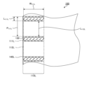
- FIG. 2 is an enlarged plan view showing a schematic view of the vicinity of one end (first end) of a long film according to one embodiment of the present invention.
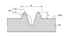
- FIG. 3 is a cross-sectional view that typically shows a cross section of linear projections and recesses of a long film according to one embodiment of the present invention, cut along a plane perpendicular to the extending direction of the projections and recesses.
- FIG. 4 is a plan view showing a schematic planar shape of one of the concave and convex portions of a long film according to one embodiment of the present invention, as viewed from the thickness direction of the film.
- FIG. 1 is a front view showing a schematic view of a film roll according to one embodiment of the present invention.
- FIG. 2 is an enlarged plan view showing a schematic view of the vicinity of one end (first end) of a long film according to one embodiment of the present invention
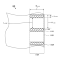
- FIG. 5 is an enlarged plan view showing a schematic view of the vicinity of the other end (second end) of the long film according to one embodiment of the present invention.
- FIG. 6 is a schematic perspective view for explaining a method for measuring the first winding diameter difference ⁇ D1 and the second winding diameter difference ⁇ D2 of a film roll.
- FIG. 7 is a schematic cross-sectional view of a film roll for explaining a method for measuring the air layer thickness d air between long films contained in the film roll.
- FIG. 8 is a schematic explanatory diagram for explaining a shape profile of the outermost peripheral surface near the end in the roll axis direction of the film roll according to one example.
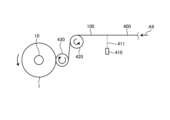
- FIG. 9 is a side view that illustrates a film roll manufacturing apparatus according to an embodiment of the present invention.
- FIG. 10 is a plan view that typically shows the state of a long film being wound around a core in a film roll manufacturing method according to one embodiment of the present invention.
- FIG. 11 is a front view showing a schematic diagram of a film roll according to a modified example of the embodiment of the present invention.
- FIG. 12 is an enlarged plan view illustrating a schematic view of the vicinity of one end (first end) of a long film according to a modified example of one embodiment of the present invention.
- Fig. 1 is a front view showing a film roll 1 according to one embodiment of the present invention.
- Fig. 1 shows a state in which a part of a long film 100 is pulled out from the film roll 1, but the part of the long film 100 does not have to be pulled out.
- the film roll 1 according to this embodiment has a winding core 10 and the long film 100 wound around the winding core 10.
- the film longitudinal direction, film width direction, and film thickness direction of the long film 100 correspond to the roll circumferential direction, roll axial direction, and roll radial direction of the film roll 1.
- the core 10 is a member having a peripheral surface 10S having a cylindrical side shape, for example, a cylindrical or columnar member.
- the peripheral surface 10S of the core 10 generally forms a smoothly curved surface, and the long film 100 is wound and overlapped on this peripheral surface 10S to form a film roll 1.
- the diameter of the core 10 may be appropriately selected depending on factors such as the material, application, and length of the long film 100.
- the specific diameter of the core 10 is preferably 100 mm or more, more preferably 150 mm or more, and preferably 400 mm or less, more preferably 350 mm or less.
- the long film 100 is a long film.
- a "long” film refers to a film having a length that is 5 times or more its width, preferably 10 times or more its width, and specifically refers to a film having a length that can be wound into a roll for storage or transportation. There is no particular upper limit to the length of the long film 100, and it can be, for example, 100,000 times or less its width.
- the long film 100 includes two knurl regions 110L and 110R, each including a plurality of convex portions, provided at both ends in the film width direction, and a flat region 120 provided between these two knurl regions 110L and 110R.
- first end one end of the long film 100 in the film width direction
- second end one end of the long film 100 in the film width direction
- multiple uneven portions 130 including concave and convex portions
- knurl regions 110L and 110R each including a plurality of convex portions in the uneven portion 130, are provided at both ends in the film width direction of the long film 100.
- FIG. 2 is an enlarged plan view showing a schematic view of the vicinity of one end (first end) of a long film 100 according to one embodiment of the present invention.
- a knurl region 110L at the first end of the long film 100 includes knurl portions 111L and spacing portions 112L that alternate in the longitudinal direction of the film.
- the knurl portion 111L represents a portion within the knurl region 110L that has a convex portion.
- the uneven portion 130 which includes concave and convex portions, is formed in the long film 100 as described above, and multiple knurl portions 111L, which include convex portions within the uneven portion 130, are formed side by side in the knurl region 110L.
- the uneven portion 130 is formed in a continuous line when viewed in the thickness direction of the film.
- Such a continuous linear uneven portion 130 can be formed, for example, by irradiating with laser light. Therefore, the uneven portion 130 may be formed as a continuous line in a single stroke, as a trace of the movement of the irradiation point of the laser light.
- "in a single stroke” refers to the shape of a line that is continuous without interruption.
- the uneven portion 130 may include a recess 131 and a protrusion 132.
- the uneven portion 130 formed by irradiation with a laser beam usually has a recess 131 and a protrusion 132 provided on both sides of the recess 131.
- the recess 131 may correspond to a portion where the resin has been removed by thermal melting or ablation caused by irradiation with a laser beam.
- the protrusion 132 may correspond to a portion where the resin that has been heated and fluidized by irradiation with the laser beam is raised. Since the protrusion 132 protrudes from the surface 100U of the surrounding long film 100, the effective thickness of the long film 100 is thicker in the knurl portion 111L having the uneven portion 130.
- the height H of the convex portion 132 may be uniform or non-uniform.
- the range of the height of the convex portion 132 is preferably 1 ⁇ m or more, more preferably 2 ⁇ m or more, even more preferably 3 ⁇ m or more, and is preferably 10 ⁇ m or less, more preferably 9 ⁇ m or less, even more preferably 8 ⁇ m or less.
- the line width W of the uneven portion 130 may be uniform or non-uniform.
- the range of the line width W of the uneven portion 130 is preferably 0.1 ⁇ m or more, more preferably 0.15 ⁇ m or more, even more preferably 0.2 ⁇ m or more, and is preferably 1 ⁇ m or less, more preferably 0.75 ⁇ m or less, even more preferably 0.5 ⁇ m or less.
- the continuous linear uneven portion 130 may be formed to have a specific planar shape, if necessary.
- planar shape refers to the shape as viewed from the film thickness direction, unless otherwise specified.
- the concave portions 131 and convex portions 132 contained in the uneven portion 130 may also have the specific planar shape.
- the continuous linear uneven portion 130 may have a shape with multiple corners.
- a corner 133 of the concave-convex portion 130 may be a connecting portion connecting two straight line portions 134 and 135 included in the concave-convex portion 130.
- the corner 133 may correspond to the apex of an angle formed between the straight line portion 134 that slopes upward to the right and the straight line portion 135 that slopes downward to the right.
- the corner 133 may have an angle ⁇ 133 that corresponds to the direction in which the straight line portion 134 extends and the direction in which the straight line portion 135 extends.
- the angle ⁇ 133 of the corner 133 is preferably in the range of 80° or more, more preferably 85° or more, and even more preferably 88° or more, and is preferably 100° or less, more preferably 95° or less, and even more preferably 92° or less.
- the angle ⁇ 133 may be 90°.
- the angles ⁇ 133 of the multiple corners 133 may be the same or different.
- the number of corners 133 included in one uneven portion 130 is not particularly limited. In this embodiment, an example is shown in which the continuous linear uneven portion 130 has an endless polygonal shape, and the number of corners 133 included in one uneven portion 130 is 24. However, the number of corners 133 included in one uneven portion 130 may be 24 or more (e.g., 32, 40, 48, 56), or may be less than 24 (e.g., 16, 8, 4).
- the planar shape of the uneven portion 130 may be a shape other than an endless shape, and may be, for example, a shape with ends such as a broken line.
- the range of the length L 111L of each knurl portion 111L in the longitudinal direction of the film is usually 20 mm or less, preferably 19 mm or less, more preferably 15 mm or less, and even more preferably 10 mm or less.
- the length L 111L is equal to or less than the upper limit, the knurl portion 111L (and the uneven portion 130 in the knurl portion 111L) can be formed in a short time, so that the production speed of the film roll 1 can be improved.
- the lower limit of the range of the length L 111L of the knurl portion 111L may be set within a range in which a film roll 1 having a desired shape profile can be obtained, and is preferably 0.1 mm or more, more preferably 0.5 mm or more, and even more preferably 1 mm or more.
- the length of the uneven portion 130 in the longitudinal direction of the film corresponds to the length L 111L of the knurl portion 111L.
- the lengths L111L of the multiple knurled portions 111L may be the same or different.
- the range of the width W 111L of each knurl portion 111L in the film width direction is preferably 3 mm or more, more preferably 5 mm or more, and even more preferably 7 mm or more, and is preferably 20 mm or less, more preferably 17 mm or less, and even more preferably 15 mm or less.
- the width of the uneven portion 130 in the film width direction corresponds to the width W 111L of the knurl portion 111L.
- the widths W 111L of the multiple knurl portions 111L may be the same or different.
- the positions of the multiple uneven portions 130 formed in the knurl region 110L in the film width direction may be different, but are usually the same.
- the positions of the multiple knurl portions 111L including the uneven portions 130 in the film width direction may also be the same.
- the width W 111L of each knurl portion 111L in the film width direction may match the width (dimension in the film width direction) of the knurl region 110L including the knurl portion 111L.
- the range of the pitch P 110L of the knurl portion 111L in the longitudinal direction of the film is preferably 20 mm or more, more preferably 25 mm or more, even more preferably 30 mm or more, and preferably 100 mm or less, more preferably 85 mm or less, even more preferably 70 mm or less.
- This pitch P 110L usually corresponds to the sum of the length L 111L of one knurl portion 111L and the length L 112L of the interval portion 112L immediately downstream of the knurl portion 111L in the longitudinal direction of the film.
- the pitch P 111L of the knurl portion 111L can correspond to the distance in the longitudinal direction of the film from the start point of formation of the uneven portion 130 by the laser light (the point where the laser light begins to hit) to the start point of formation of the next uneven portion 130.
- the pitches P 111L of the multiple knurled portions 111L may be the same or different.
- the spacing portion 112L represents a portion within the knurl region 110L that does not have a protruding portion.
- a plurality of these spacing portions 112L are formed side by side as portions between the plurality of knurl portions 111L.
- the spacing portion 112L does not have an uneven portion 130 formed therein, and therefore does not have a protruding portion 132. And, since it does not have a protruding portion 132, the actual thickness of the long film 100 is thinner in the spacing portion 112L than in the knurl portion 111L.
- the range of the length L 112L of each of the spacing portions 112L in the longitudinal direction of the film is preferably 15 mm or more, more preferably 20 mm or more, and even more preferably 25 mm or more, and is preferably 95 mm or less, more preferably 80 mm or less, and even more preferably 65 mm or less.
- the distance in the longitudinal direction of the film between adjacent uneven portions 130 corresponds to the length L 112L of the spacing portion 112L.
- the lengths L 112L of the multiple spacing portions 112L may be the same or different.
- the ratio ( L112L / L111L ) of the length L111L of the knurl portion 111L to the length L112L of the spacing portion 112L in the longitudinal direction of the film is preferably 5 or more, more preferably 10 or more, even more preferably 20 or more, and preferably 100 or less, more preferably 60 or less, and even more preferably 40 or less.
- the ratio of the average of those lengths L111L to the average of those lengths L112L is within the above-mentioned range.
- the knurl region 110L including the knurl portion 111L and the spacing portion 112L described above is provided at the first end of the long film 100, as described above.
- the distance from the edge 140L on the first end side of the long film 100 to the knurl region 110L may be 0 mm or may be greater than 0 mm. Therefore, the long film 100 may have an arbitrary region outside the knurl region 110L in the film width direction.
- the flat region 120 of the long film 100 is generally used for the final use, from the viewpoint of widening the range of use for such final use, it is preferable that the arbitrary region is small, and more preferable that there is no arbitrary region.
- the knurl region 110L has a width in the same range as the width W 111L of the knurl portion 111L included in the knurl region 110L.
- the knurl region 110R at the second end of the long film 100 includes knurl portions 111R and spacing portions 112R that are arranged alternately in the longitudinal direction of the film.
- This knurl region 110R and the knurl portions 111R and spacing portions 112R included in the knurl region 110R may be formed in the same manner as the knurl region 110L and the knurl portions 111L and spacing portions 112L included in the knurl region 110L described above, except that they are provided at the second end of the long film 100 in the film width direction.
- the knurl portion 111R represents a portion in the knurl region 110R having a convex portion.
- the uneven portion 130 is formed in the long film 100, and thus a plurality of knurl portions 111R including the convex portions 132 (see FIG. 3) in the uneven portion 130 are formed side by side in the knurl region 110R.
- the uneven portion 130, the concave portion 131 (see FIG. 3), and the convex portion 132 in the knurl portion 111R may be the same as the uneven portion 130, the concave portion 131, and the convex portion 132 in the knurl portion 111L.
- the range of the length L 111R per knurl portion 111R in the longitudinal direction of the film, the range of the width W 111R per knurl portion 111R in the width direction of the film, and the range of the pitch P 110R of the knurl portion 111R in the longitudinal direction of the film may be the same as the range of the length L 111L per knurl portion 111L in the longitudinal direction of the film, the range of the width W 111L per knurl portion 111L in the width direction of the film, and the range of the pitch P 110L of the knurl portion 111L in the longitudinal direction of the film.
- the positions of the multiple uneven portions 130 formed in the knurl region 110R in the width direction of the film may be different, but are usually the same.
- the positions of the multiple knurl portions 111R including the uneven portions 130 in the width direction of the film may also be the same.
- the width W 111R of each knurl portion 111R in the film width direction can be equal to the width (dimension in the film width direction) of the knurl region 110R including that knurl portion 111R.
- the spacing portion 112R represents a portion in the knurl region 110R that does not have a convex portion.
- the uneven portion 130 is not formed in the spacing portion 112R, so the spacing portion 112R does not have a convex portion 132.
- the range of the length L 112R per spacing portion 112R in the film longitudinal direction and the range of the ratio (L 112R /L 111R ) between the length L 111R of the knurl portion 111R and the length L 112R of the spacing portion 112R in the film longitudinal direction may be the same as the range of the length L 112L per spacing portion 112L in the film longitudinal direction and the range of the ratio (L 112L /L 111L ) between the length L 111L of the knurl portion 111L and the length L 112L of the spacing portion 112L in the film longitudinal direction.
- the ratio of the average of the lengths L111R to the average of the lengths L112R is within the above range.
- the long film 100 may have an arbitrary region outside the knurl region 110R in the film width direction.
- the distance from the edge 140R on the second end side of the long film 100 to the knurl region 110R may be 0 mm or may be greater than 0 mm.
- the arbitrary region is small, and more preferably, there is no arbitrary region.
- the knurl region 110R has a width in the same range as the width W 111R of the knurl portion 111R included in the knurl region 110R.
- the long film 100 has a flat region 120 between the two knurl regions 110L and 110R in the film width direction.
- This flat region 120 does not usually have a protrusion 132 (see FIG. 3), so its effective thickness is smaller than the knurl portions 111L and 111R of the knurl regions 110L and 110R.
- this flat region 120 is used for the final use of the long film 100.
- the length, width, and thickness of the long film 100 may be set within a range according to the intended use of the long film 100.
- the length of the long film 100 is preferably 2000 m or more, more preferably 2500 m or more, even more preferably 3000 m or more, and is preferably 10000 m or less, more preferably 8000 m or less, even more preferably 6000 m or less.
- the width of the long film 100 is preferably 700 mm or more, more preferably 1000 mm or more, even more preferably 1200 mm or more, and is preferably 2500 mm or less, more preferably 2200 mm or less, even more preferably 2000 mm or less.
- the thickness of the long film 100 is preferably 11 ⁇ m or more, more preferably 15 ⁇ m or more, and even more preferably 20 ⁇ m or more, and is preferably 500 ⁇ m or less, more preferably 300 ⁇ m or less, and even more preferably 150 ⁇ m or less.
- the "thickness of the long film 100" refers to the thickness of the long film 100 in a portion without the uneven portion 130, and usually refers to the thickness in the flat region 120.
- the film roll 1 can suppress gauge bands, bump defects, and edge defects, so that even when such a thin long film 100 is used, the occurrence of defects due to storage and transportation in the film roll 1 state can be suppressed, and therefore excellent quality stability can be achieved.
- the film roll 1 is a roll of the long film 100 including the two knurl regions 110L and 110R and the flat region 120 provided between the two knurl regions 110L and 110R.
- the film roll 1 includes two large diameter portions 210L and 210R around which the knurl regions 110L and 110R are wound, and a small diameter portion 220 around which the flat region 120 is wound.
- the large diameter portions 210L and 210R are usually provided at both ends of the film roll 1 in the roll axis direction.
- the large diameter portion 210L formed by winding the knurl region 110L at the first end of the long film 100 may be referred to as the "first large diameter portion” 210L
- the large diameter portion 210R formed by winding the knurl region 110R at the second end of the long film 100 may be referred to as the "second large diameter portion” 210R.
- the first large diameter portion 210L and the second large diameter portion 210R have a relatively larger diameter than the small diameter portion 220 because they are portions where the knurl regions 110L and 110R including the knurl portions 111L and 111R, which have a relatively large effective thickness, are wound up.
- the small diameter portion 220 is usually provided between the two large diameter portions 210L and 210R in the roll axis direction of the film roll 1.
- the small diameter portion 220 is usually a portion where the flat region 120, which has a smaller effective thickness than the knurl portions 111L and 111R of the knurl regions 110L and 110R, is wound, so it has a relatively smaller diameter than the first large diameter portion 210L and the second large diameter portion 210R.
- This film roll 1 satisfies the following requirements (R1), (R2), and (R3) in combination.
- R1 Both the first winding diameter difference ⁇ D1 and the second winding diameter difference ⁇ D2 of the film roll 1 are smaller than 0.3 mm.
- R2 At least one of the first winding diameter difference ⁇ D1 and the second winding diameter difference ⁇ D2 of the film roll 1 is 0.05 mm or more.
- R3 The air layer thickness d air between the wound long films 100 at the center of the film roll 1 in the roll axis direction is 0.9 ⁇ m or more and 2.0 ⁇ m or less.
- Both the first winding diameter difference ⁇ D1 and the second winding diameter difference ⁇ D2 of the film roll 1 are usually less than 0.30 mm, preferably less than 0.20 mm, and more preferably less than 0.15 mm.
- the first winding diameter difference ⁇ D1 of the film roll 1 represents a value represented by the following formula (1).
- the second winding diameter difference ⁇ D2 of the film roll 1 represents a value represented by the following formula (2).
- D N1(MAX) represents the maximum value of the diameter of the first large diameter portion (one of the two large diameter portions) 210L of the film roll 1; D F1(AVE) represents the average value of the diameter of the small diameter portion 220 on the side of the first large diameter portion (one of the large diameter portions) 210L of the film roll 1.
- D N2(MAX) represents the maximum value of the diameter of the second large diameter portion (the other of the two large diameter portions) 210R of the film roll 1; D F2(AVE) represents the average value of the diameter of the small diameter portion 220 on the side of the second large diameter portion (the other large diameter portion) 210R of the film roll 1.
- the first winding diameter difference ⁇ D1 and the second winding diameter difference ⁇ D2 of the film roll 1 can be measured by the following measurement method.
- FIG. 6 is a schematic perspective view for explaining the measurement method of the first winding diameter difference ⁇ D1 and the second winding diameter difference ⁇ D2 of the film roll 1. As shown in FIG. 6, a laser displacement meter 300L and a laser displacement meter 300R are installed facing the film roll 1 at a position away from the outermost surface 1S of the film roll 1.
- the laser displacement meter 300L and the laser displacement meter 300R are installed so that the optical axes 310L and 310R of the measurement laser light emitted from the laser displacement meter 300L and the laser displacement meter 300R are perpendicular to the central axis 10A of the winding core 10.
- the distance from the laser displacement meter 300L and 300R to the surface of the winding core 10 can be, for example, 580 mm.
- the laser displacement meters 300L and 300R measure the distance from the laser displacement meters 300L and 300R to the outermost surface 1S of the film roll 1. This measurement gives the distance from the laser displacement meters 300L and 300R to the outermost surface 1S of the film roll 1 when the circumferential rotation angle ⁇ of the film roll 1 is in the range of 0° ⁇ 360°.
- a shape profile of the outermost surface 1S of the small diameter portion 220 is obtained, and the diameter of the small diameter portion 220 is obtained from the shape profile.
- D F1 AVE
- the shape profile of the outermost surface 1S is measured in the small diameter portion 220 on the first large diameter portion 210L side of the film roll 1.
- the shape profile of the outermost surface 1S is measured in a measurement range 221L in the small diameter portion 220 that is 10 cm to 20 cm away in the roll axis direction from the inner end (the inner end in the roll axis direction) of the first large diameter portion 210L.
- the diameter of the small diameter portion 220 on the first large diameter portion 210L side is obtained from the shape profile, and the average of the measured values of the diameter of the small diameter portion 220 on the first large diameter portion 210L side when the rotation angle ⁇ is 0° ⁇ 360° is calculated as D F1 (AVE) . Furthermore, in order to obtain D F2(AVE) , the shape profile of the outermost surface 1S is usually measured in the small diameter portion 220 on the second large diameter portion 210R side of the film roll 1.
- the shape profile of the outermost surface 1S is measured in a measurement range 221R in the small diameter portion 220 that is 10 cm to 20 cm away in the roll axis direction from the inner end (the inner end in the roll axis direction) of the second large diameter portion 210R. Then, the diameter of the small diameter portion 220 on the second large diameter portion 210R side is obtained from the shape profile, and the average of the measured values of the diameter of the small diameter portion 220 on the second large diameter portion 210R side when the rotation angle ⁇ is 0° ⁇ 360° is calculated as D F2(AVE) .
- the obtained D N1(MAX) and D F1(AVE) are substituted into the formula (1) to calculate the first winding diameter difference ⁇ D1 of the film roll 1.
- This first winding diameter difference ⁇ D1 corresponds to the difference in diameter between the first large diameter portion 210L and the small diameter portion 220 on the inside in the roll axis direction, and corresponds to the size of the step that may occur between the first large diameter portion 210L and the small diameter portion 220.
- the obtained D N2(MAX) and D F2(AVE) are substituted into the formula (2) to calculate the second winding diameter difference ⁇ D2 of the film roll 1.
- This second winding diameter difference ⁇ D2 corresponds to the difference in diameter between the second large diameter portion 210R and the small diameter portion 220 on the inside in the roll axis direction, and corresponds to the size of the step that may occur between the second large diameter portion 210R and the small diameter portion 220.
- the requirement (R1) indicates that these steps are smaller than a certain threshold value.
- At least one of the first winding diameter difference ⁇ D1 and the second winding diameter difference ⁇ D2 of the film roll 1 is usually 0.05 mm or more, preferably 0.06 mm or more, and more preferably 0.07 mm or more. It is further preferable that both of the first winding diameter difference ⁇ D1 and the second winding diameter difference ⁇ D2 of the film roll 1 are equal to or more than the above threshold value.
- the first winding diameter difference ⁇ D1 corresponds to the difference in diameter between the first large diameter portion 210L and the small diameter portion 220 on the inside in the roll axis direction, and corresponds to the size of the step that may occur between the first large diameter portion 210L and the small diameter portion 220.
- the second winding diameter difference ⁇ D2 corresponds to the difference in diameter between the second large diameter portion 210R and the small diameter portion 220 on the inside in the roll axis direction, and corresponds to the size of the step that may occur between the second large diameter portion 210R and the small diameter portion 220. Therefore, requirement (R1) indicates that at least one of these steps, and preferably both, is equal to or greater than a certain threshold value.
- the air layer thickness d air between the wound long film 100 at the center of the roll axis direction of the film roll 1 is usually 0.9 ⁇ m or more, preferably 1.0 ⁇ m or more, and usually 2.0 ⁇ m or less, preferably 1.7 ⁇ m or less, more preferably 1.4 ⁇ m or less.
- the air layer thickness d air represents the thickness of one air layer between the adjacent long films 100 wound in layers within the film roll 1.
- the air layer thickness d air can be measured by the following measurement method.
- FIG. 7 is a schematic cross-sectional view of the film roll 1 for explaining a method for measuring the air layer thickness d air between the long films 100 included in the film roll 1.
- a laser displacement meter 300L is installed facing the film roll 1 in the same manner as the above-mentioned method for measuring the first winding diameter difference ⁇ D1 and the second winding diameter difference ⁇ D2 of the film roll 1.
- the laser displacement meter 300L measures the distance from the laser displacement meter 300L to the outermost surface 1S of the film roll 1 at the center of the roll axis direction of the film roll 1.
- This measurement provides the distance from the laser displacement meter 300L to the outermost surface 1S of the film roll 1 when the circumferential rotation angle ⁇ (see FIG. 6) of the film roll 1 is in the range of 0° ⁇ 360°. Then, from the measurement results, a shape profile of the outermost surface 1S at the center of the roll axis direction of the film roll 1 is obtained, and an average diameter Rb is obtained when the rotation angle ⁇ is 0° ⁇ 360°.
- the average radius Ra of the core 10 at the center of the film roll 1 in the roll axis direction, the thickness d film of one sheet of the long film 100 at the center of the long film 100 in the film width direction, and the length L of the long film 100 are measured.
- the average radius Rb of the film roll 1 is expressed by the following formula (M1).
- the length L of the long film 100 contained in the film roll 1 is generally expressed by the following formula (M2).
- n represents the total number of turns of the long film 100 contained in the film roll 1.
- formula (M2) since n>>1, n+1 can be approximated as n+1 ⁇ n. Therefore, when n+1 in formula (M2) is approximated to n, the total number of turns n can be expressed by formula (M3). Furthermore, by solving formula (M1), the air layer thickness d air can be expressed by formula (M4). Therefore, the air layer thickness d air can be calculated using formulas (M3) and (M4) from the average radius Rb of the film roll 1, the average radius Ra of the winding core 10, the thickness d film of one film at the center of the long film 100 in the film width direction, and the length L of the long film 100.
- the film roll 1 according to this embodiment which satisfies the above-mentioned requirements (R1), (R2), and (R3) in combination, can suppress gauge bands, bump defects, and edge defects. This allows for excellent appearance stability and quality stability during transportation and storage, and is expected to lead to improved yields.
- the details are as follows.
- the film roll 1 according to this embodiment can suppress the occurrence of gauge bands. This can suppress the occurrence of defects in the long film 100 contained in the film roll 1 due to bending of the long film 100.
- the film roll 1 when the film roll 1 is stored for 14 days in an environment with a temperature of 20°C to 25°C and a humidity of 50% RH to 70% RH, the occurrence of gauge bands (localized band-shaped defects extending in the circumferential direction) can be suppressed.
- gauge bands are generally prone to occur when the air layers between the long films 100 in the overlapping film roll 1 are too small.
- requirement (R3) sufficient air layers are formed between the long films 100 in the film roll 1 to prevent the occurrence of gauge bands, so that the formation of gauge bands can be prevented.
- the film roll 1 according to this embodiment can suppress the occurrence of buckling. Therefore, the occurrence of lumpy defects caused by the buckling can be suppressed.
- the film roll 1 when the film roll 1 is stored for 14 days in an environment with a temperature of 20°C to 25°C and a humidity of 50% RH to 70% RH, the occurrence of lumpy defects in the long film 100 contained in the film roll 1 can be suppressed.
- the lumpy defects are usually observed as defects with a depth of 3 ⁇ m to 5 ⁇ m and a width of 3 mm to 5 mm.
- the lumpy defects can be detected by unwinding the long film 100 from the film roll 1 at a line speed of 50 m/min and using a defect detector.
- this defect detector a detector that can irradiate light onto the long film 100 and detect defects based on the state of light reflected from the long film 100 can be used.
- the long film is buckled, the light reflection state changes from a portion where there is no buckling, so the lumpy defects can be detected by the defect detector.
- defects that are between 0 mm and 40 mm inward from the knurl area in the film width direction are not included in the lump defects.
- lumpy defects are generally likely to occur due to buckling, which occurs when the air layer between the long films 100 in the overlapping film roll 1 becomes excessively large.
- the air layer between the long films 100 can be made thin enough to prevent buckling, so that buckling can be prevented, and therefore lumpy defects can also be prevented.
- the film roll 1 can suppress edge defects.
- the occurrence of edge defects in the long film 100 contained in the film roll 1 can be suppressed.
- the edge defects are usually observed as defects with a depth of 3 ⁇ m to 5 ⁇ m and a width of 3 mm to 5 mm.
- the edge defects can be detected by unwinding the long film 100 from the film roll 1 at a line speed of 50 m/min and using the defect detector.
- the defect detector In order to evaluate edge defects separately from bump defects, only defects that are within a distance of 0 mm to 40 mm inside the knurl area in the film width direction are detected as edge defects.
- FIG. 8 is a schematic diagram for explaining the shape profile of the outermost surface near the end in the roll axis direction of a film roll 1 according to an example.
- the roll film 1 has a relatively large diameter in the large diameter portion (i.e., the first large diameter portion 210L and the second large diameter portion 210R), and a relatively small diameter in the small diameter portion 220 located inside in the roll axis direction.
- the diameter may become particularly small locally due to the movement of the long film 100 due to gravity.
- a large step may be formed at the boundary portion 230.
- the first winding diameter difference ⁇ D1 and the second winding diameter difference ⁇ D2 corresponding to the step can be made smaller than an appropriate threshold value confirmed experimentally. Therefore, buckling at the boundary portion 230 can be suppressed, and the occurrence of end defects can be suppressed.
- the lower limits of the first winding diameter difference ⁇ D1 and the second winding diameter difference ⁇ D2 are set to an appropriate threshold value or higher, thereby achieving the suppression of all gauge bands, bump defects, and end defects.
- the knurl portions 111L and 111R including the convex portions are not densely arranged in the knurl regions 110L and 110R, but are formed with a large pitch P111L and P111R by leaving intervals 112L and 112R between them.
- the knurl portions 111L with a large pitch P111L the knurl portions 111L of the long film 100 that is wound up are reduced from piling up in the first large diameter portion 210L in which the knurl region 110L is wound.
- the knurl portions 111L can be overlapped with each other by shifting their positions in the roll circumferential direction, so that the diameter of the first large diameter portion 210L does not become excessively large and can be within an appropriate range.
- the knurl portions 111R at a large pitch P 111R , it is possible to reduce the stacking of the knurl portions 111R of the long film 100 being wound and overlapped even in the second large diameter portion 210R where the knurl region 110R is wound, so that the diameter of the second large diameter portion 210R does not become excessively large and can be kept within an appropriate range. Therefore, in this embodiment, the first winding diameter difference ⁇ D1 and the second winding diameter difference ⁇ D2 can be kept within an appropriate range that satisfies the requirements (R1) and (R2).
- the method for satisfying requirements (R1) and (R2) is as described above. Therefore, it is preferable to set the dimensions and positions of the knurled portions 111L and 111R and the spacing portions 112L and 112R of the long film 100 so as to satisfy requirements (R1) and (R2). For example, it is preferable to select and adopt values within the above-mentioned ranges that provide the desired first winding diameter difference ⁇ D1 and second winding diameter difference ⁇ D2.
- the convex portion 132 of an appropriate height according to the dimensions and positions of the knurl portions 111L and 111R and the spacing portions 112L and 112R, and to manufacture the film roll 1 by a method including the knurl touch winding method described later.
- the air layer thickness d air can be reduced compared to the height of the convex portion 132 of the knurl portions 111L and 111R. Therefore, a small air layer thickness d air that satisfies the requirement (R3) can be obtained.
- the above-mentioned film roll 1 can be manufactured by a manufacturing method including winding the long film 100 around the core 10 by the knurled touch winding method.
- the manufacturing method of the film roll 1 using the knurled touch winding method is as follows: A step (S2) of winding the long film 100 around a touch roll; A step (S3) of winding the long film 100 wound around the touch roll onto the winding core 10 while bringing the touch roll into contact with the knurled regions 110L and 110R of the long film 100;
- the composition can be produced by a method comprising the steps of:
- the method for producing the film roll 1 includes the steps of: A step (S1) of forming the knurl portions 111L and 111R on the long film before the knurl portions 111L and 111R are formed to obtain the long film 1 having the knurl portions 111L and 111R.
- the "long film before the formation of the knurl portions 111L and 111R" may be referred to as the "unprocessed film.”
- the manufacturing method of the film roll 1 including these steps (S1) to (S3) will be described with reference to the drawings.
- FIG. 9 is a side view showing a schematic diagram of a manufacturing device for a film roll 1 according to one embodiment of the present invention.
- a typical manufacturing method for a film roll 1 involves winding up a long film 100 while continuously transporting it in the film's longitudinal direction.
- a knurled portion (not shown in FIG. 9) is formed in an unprocessed film 400 by a processing device 410 to obtain a long film 100, and the long film 100 is then supplied to a touch roll 430 via a transport roll 420 and wound around a core 10.
- the long unprocessed film 400 is transported in the longitudinal direction of the film as indicated by arrow A9, and is supplied to a processing device 410.
- a convex portion is formed on the unprocessed film 400 supplied to the processing device 410, and a long film 100 including a knurl portion is obtained (step (S1)).
- the processing device 410 it is preferable to use a laser processing device capable of forming knurled portions by irradiating laser light as the processing device 410.
- the laser light 411 is irradiated onto the unprocessed film 400 while moving the irradiation point at which the laser light 411 hits the unprocessed film 400.
- the concave-convex portion 130 can be formed at the point irradiated with the laser light 411 on the unprocessed film 400, and a long film 100 having the knurled portions 111L and 111R can be obtained.
- the irradiation point where the laser light 411 hits the unprocessed film 400 is moved so as to trace the planar shape of the desired unevenness 130 to be formed.
- the unevenness 130 is formed at the trace of the movement of the irradiation point of the laser light 411, so that the unevenness 130 having the desired planar shape can be formed.
- the moving speed of the irradiation point of the laser light 411 can be appropriately set within a range in which the desired uneven portion 130 can be formed.
- the range of the moving speed of the irradiation point of the laser light 411 is preferably 500 mm/s or more, more preferably 1000 mm/s or more, even more preferably 1500 mm/s or more, and preferably 10000 mm/s or less, more preferably 9000 mm/s or less, even more preferably 8000 mm/s or less.
- the specific moving speed may be adjusted within the above range so that an uneven portion 130 having a convex portion 132 (see FIG. 3) of the desired height is obtained.
- laser devices that irradiate laser light 411 include ArF excimer laser devices, KrF excimer laser devices, XeCl excimer laser devices, YAG laser devices (particularly third or fourth harmonic), YLF or YVO4 solid-state laser devices (particularly third or fourth harmonic), Ti:S laser devices, semiconductor laser devices, fiber laser devices, and carbon dioxide laser devices.
- ArF excimer laser devices KrF excimer laser devices, XeCl excimer laser devices, YAG laser devices (particularly third or fourth harmonic), YLF or YVO4 solid-state laser devices (particularly third or fourth harmonic), Ti:S laser devices, semiconductor laser devices, fiber laser devices, and carbon dioxide laser devices.
- carbon dioxide laser devices are preferred from the viewpoints of being relatively inexpensive and being able to efficiently obtain an output suitable for film processing.
- the range of the output of the laser light is preferably 1 W or more, more preferably 5 W or more, even more preferably 15 W or more, and preferably 120 W or less, more preferably 100 W or less, even more preferably 80 W or less, even more preferably 70 W or less.
- the specific output may be adjusted within the above range so as to obtain the uneven portion 130 having the convex portion 132 of the desired height.
- knurled portions 111L and 111R are formed in the unprocessed film 400, and the long film 100 to be wound is obtained.
- This long film 100 is supplied to the touch roll 430 via the transport roll 420.
- the long film 100 supplied to the touch roll 430 is wound around the touch roll 430 (step (S2)).
- the touch roll 430 is a roll having a length in the roll axis direction equal to or greater than the width of the long film 100, and is provided so as to be rotatable in the circumferential direction around its rotation axis (not shown).
- the touch roll 430 may be provided so as to be freely rotatable. When the touch roll 430 is provided so as to be freely rotatable, the touch roll 430 can rotate in the circumferential direction by the frictional force applied by the wound long film 100.
- the touch roll 430 may also be rotationally driven by a rotational driving force applied by a driving device (not shown).
- the touch roll 430 may be provided with a rotational driving force to an extent that mechanical loss can be reduced.
- the long film 100 wound around the touch roll 430 is guided to the winding core 10 by the rotating touch roll 430.
- the core 10 is usually rotated in the circumferential direction by a drive device (not shown).
- the long film 100 which is guided to the core 10 while wrapped around the touch roll 430, is wound onto the core 10 to obtain the film roll 1 (step (S3)).
- Figure 10 is a plan view that shows a schematic of the state of the long film 100 being wound around the core 10 in a manufacturing method of a film roll 1 according to one embodiment of the present invention.
- the long film 100 wound around the touch roll 430 is wound around the core 10 while the touch roll 430 is in contact with the knurl regions 110L and 110R of the long film 100 that has already been wound around the core 10 and become part of the film roll 1 in the process of being manufactured.
- the touch roll 430 presses the film roll 1 in the process of being manufactured toward the center of the winding core 10 in the radial direction of the winding core 10 with a specific load.
- a biasing device such as an air cylinder may be provided on a support arm (not shown) that supports the touch roll 430, and the touch roll 430 may press the film roll 1 by the biasing device. This allows the knurl regions 110L and 110R of the long film (i.e., the long film included in the film roll 1 in the process of being manufactured) 100 wound around the winding core 10 to be pressed toward the center of the winding core 10 with a specific load.
- the long film 100 wound around the touch roll 430 is wound around the core 10 while the touch roll 430 does not come into contact with the flat area 120 of the long film 100 that has already been wound around the core 10 and is part of the film roll 1 in the process of being manufactured.
- This allows air to be effectively drawn in between the overlapping flat areas 120.
- an air layer thickness d air that satisfies the requirement (R3) can be obtained.
- the air layer thickness d air can be adjusted by the height of the convex portion 132 (not shown in FIG. 10) of the knurled portions 111L and 111R.
- the fact that the air layer thickness d air can be adjusted by the height of the convex portion 132 in this way is one of the advantages of the touch roll winding method.
- the magnitude of the load with which the touch roll 430 presses the film roll 1 in the middle of production is preferably set so that the touch roll 430 comes into contact with the knurled regions 110L and 110R of the long film 100 wound around the core 10, and the touch roll does not come into contact with the flat region 120 of the long film 100 wound around the core 10.
- the range of the load is preferably 50 N/m or more, more preferably 60 N/m or more, even more preferably 70 N/m or more, and preferably 200 N/m or less, more preferably 180 N/m or less, and even more preferably 160 N/m or less.
- the unit of the load "N/m" represents the magnitude of the force applied per meter of the width of the long film 100.
- the specific magnitude of the load is preferably selected and set from the above range so as to satisfy the requirements (R1) to (R3).
- the magnitude of the load with which the touch roll 430 presses the film roll 1 during production may be changed according to the winding diameter of the film roll 1 during production.
- the magnitude of the load may be changed to gradually decrease, or to gradually increase, or a combination of these may be used.
- the winding tension (film tension) of the long film 100 at the start of winding is preferably 10 N/m or more, more preferably 50 N/m or more, even more preferably 80 N/m or more, and is preferably 200 N/m or less, more preferably 170 N/m or less, even more preferably 140 N/m or less.
- the winding tension may be constant at the start of winding, or may be changed. For example, the tension may be gradually reduced from the winding tension Ts at the start of winding the long film 100 as winding progresses.
- the tension taper ratio (%) is preferably 5% or more, more preferably 10% or more, even more preferably 15% or more, and is preferably 50% or less, more preferably 40% or less, and even more preferably 30% or less.
- the range of the winding speed (line speed) of the long film 100 is preferably 10 m/min or more, more preferably 20 m/min or more, even more preferably 30 m/min or more, and preferably 150 m/min or less, more preferably 125 m/min or less, and even more preferably 100 m/min or less.
- the above-mentioned film roll 1 can be manufactured by winding the long film 100 at such a high speed, which can contribute to improving manufacturing efficiency.
- the step (S1) of the method for producing a film roll may include oscillating the position where the knurled portion is formed in the film width direction.
- FIG. 11 is a front view showing a film roll 2 according to a modified example of the embodiment of the present invention.
- FIG. 12 is a plan view showing an enlarged view of the vicinity of one end (first end) of the long film 500 according to the modified example of the embodiment of the present invention.
- the film roll 2 and the long film 500 shown in FIG. 11 and FIG. 12 are provided in the same manner as the film roll 1 and the long film 100 according to the embodiment described above, except that the position of the uneven portion 130 is oscillated in the film width direction.
- FIG. 11 and FIG. 12 when the position for forming the knurl portion 111L (and the knurl portion 111R; see FIG.
- the first winding diameter difference ⁇ D1 and the second winding diameter difference ⁇ D2 can be easily reduced.
- the degree of oscillation can be represented by the oscillation amount A O.
- the oscillation amount A O represents the amplitude of oscillation in the film width direction.
- the ratio (A O /W 111L and A O /W 111R ) of the oscillation amount A O to the widths W 111L and W 111R per knurl portion 111L and 111R is preferably 0.5 or more, more preferably 0.6 or more, and preferably 1.0 or less, more preferably 0.8 or less.
- the specific oscillation amount A O may be selected from the above range so that the first winding diameter difference ⁇ D1 and the second winding diameter difference ⁇ D2 that satisfy the requirements (R1) and (R2) are obtained.
- the oscillation period When performing the above-mentioned oscillation, it is preferable to set the oscillation period appropriately so as to obtain the first winding diameter difference ⁇ D1 and the second winding diameter difference ⁇ D2 that satisfy the requirements (R1) and (R2).
- the oscillation period may be in the range of 800 mm to 1500 mm.
- the oscillation period refers to the distance in the longitudinal direction of the film from when the knurl portion is formed at a certain position in the film width direction in a long film in which a knurl portion is formed while being transported, until the position of the knurl portion is changed by oscillation and the knurl portion is formed again in the original position.
- the knurled portion was formed as an uneven portion that includes a combination of concave and convex portions, but the knurled portion may also be formed as a convex portion without a concave portion.
- the protrusions were formed using laser light, but the protrusions may be formed by other methods.
- the protrusions may be formed by embossing using heat and pressure.
- the long film is usually a resin film.
- the resin film may be a stretched film or an unstretched film.
- the resin film may be a single-layer film having only a base layer, or a multi-layer film having any layer in combination with the base layer.
- the base layer is usually a layer made of resin.
- resins can be used as such depending on the application of the long film, but cycloolefin resin is preferable. Films with a base layer made of cycloolefin resin generally tend to entrap air when wound, and therefore have poor rollability.
- the long film according to the above-mentioned embodiment can be wound well by the Touchnar winding method.
- Cycloolefin resin is a resin containing a cycloolefin polymer.
- Cycloolefin polymers have excellent mechanical properties, heat resistance, transparency, low moisture absorption, dimensional stability, and light weight.
- Cycloolefin polymer refers to a polymer whose structural unit has an alicyclic structure.
- Cycloolefin polymers can be polymers having an alicyclic structure in the main chain, polymers having an alicyclic structure in the side chain, polymers having alicyclic structures in the main chain and side chain, and mixtures of two or more of these in any ratio. Among them, polymers having an alicyclic structure in the main chain are preferred from the viewpoint of mechanical strength and heat resistance.
- alicyclic structures include saturated alicyclic hydrocarbon (cycloalkane) structures and unsaturated alicyclic hydrocarbon (cycloalkene, cycloalkyne) structures.
- cycloalkane structures and cycloalkene structures are preferred, and cycloalkane structures are particularly preferred.
- the number of carbon atoms constituting the alicyclic structure is preferably 4 or more, more preferably 5 or more, and preferably 30 or less, more preferably 20 or less, and particularly preferably 15 or less per alicyclic structure.
- the number of carbon atoms constituting the alicyclic structure is within this range, the mechanical strength, heat resistance, and moldability of the resin are highly balanced.
- the proportion of structural units having an alicyclic structure is preferably 55% by weight or more, more preferably 70% by weight or more, and particularly preferably 90% by weight or more.
- the proportion of structural units having an alicyclic structure in the cycloolefin polymer is within this range, the transparency and heat resistance are good.
- Cycloolefin polymers include, for example, norbornene polymers, monocyclic cycloolefin polymers, cyclic conjugated diene polymers, vinyl alicyclic hydrocarbon polymers, and hydrogenated versions of these.
- norbornene polymers and their hydrogenated versions are particularly suitable due to their good moldability.
- Examples of norbornene-based polymers and their hydrogenated products include ring-opening polymers of monomers having a norbornene structure and their hydrogenated products; addition polymers of monomers having a norbornene structure and their hydrogenated products.
- Examples of ring-opening polymers of monomers having a norbornene structure include ring-opening homopolymers of one type of monomer having a norbornene structure, ring-opening copolymers of two or more types of monomers having a norbornene structure, and ring-opening copolymers of a monomer having a norbornene structure and any monomer that can be copolymerized therewith.
- addition polymers of monomers having a norbornene structure include addition homopolymers of one type of monomer having a norbornene structure, addition copolymers of two or more types of monomers having a norbornene structure, and addition copolymers of a monomer having a norbornene structure and any monomer that can be copolymerized therewith.
- the hydrogenated ring-opening polymer of a monomer having a norbornene structure is particularly suitable from the standpoints of moldability, heat resistance, low moisture absorption, dimensional stability, and light weight.
- the weight average molecular weight (Mw) of the cycloolefin polymer is preferably 10,000 or more, more preferably 15,000 or more, particularly preferably 20,000 or more, and is preferably 100,000 or less, more preferably 80,000 or less, particularly preferably 50,000 or less.
- Mw weight average molecular weight
- the molecular weight distribution (weight average molecular weight (Mw)/number average molecular weight (Mn)) of the cycloolefin polymer is preferably 1.2 or more, more preferably 1.5 or more, particularly preferably 1.8 or more, and is preferably 3.5 or less, more preferably 3.0 or less, particularly preferably 2.7 or less.
- Mw weight average molecular weight
- Mn number average molecular weight
- the weight average molecular weight and number average molecular weight are the weight average molecular weights converted into polyisoprene or polystyrene, measured by gel permeation chromatography using cyclohexane as a solvent. However, in the gel permeation chromatography, if the sample does not dissolve in cyclohexane, toluene may be used as the solvent.
- the glass transition temperature of the cycloolefin polymer is preferably 130°C or higher, more preferably 135°C or higher, and preferably 150°C or lower, more preferably 145°C or lower.
- the glass transition temperature is equal to or higher than the lower limit of the above range, the durability of the film at high temperatures can be improved. Also, when the glass transition temperature is equal to or lower than the upper limit of the above range, the stretching process can be easily performed.
- cycloolefin polymer for example, those described in WO 2017/145718 can be used.
- the proportion of cycloolefin polymer in the cycloolefin resin is preferably 50% to 100% by weight, more preferably 70% to 100% by weight, and particularly preferably 90% to 100% by weight. When the proportion of the polymer is within the above range, sufficient heat resistance and transparency can be obtained.
- the cycloolefin resin may contain any component other than the cycloolefin polymer in combination with the cycloolefin polymer.
- the optional components include colorants such as pigments and dyes; fluorescent brighteners; dispersants; heat stabilizers; light stabilizers; UV absorbers; antistatic agents; antioxidants; lubricants; etc. These may be used alone or in combination of two or more types.
- the substrate layer can be manufactured by molding the resin using an appropriate film molding method.
- film molding methods include cast molding, extrusion molding, and inflation molding.
- the melt extrusion method which does not use a solvent, can efficiently reduce the amount of residual volatile components, and is preferred from the viewpoints of the global environment and working environment, as well as excellent manufacturing efficiency.
- an inflation method using a die may be used, but the T-die method is preferred from the viewpoints of excellent productivity and thickness accuracy.
- the multilayer film When a multilayer film having two or more layers is used as the long film, the multilayer film preferably has a base layer and a functional layer.
- the functional layer may be provided on one side of the base layer or on both sides.
- the functional layer is preferably provided on the knurled portion side of the base layer, and more preferably the knurled portion is provided on the surface of the functional layer.
- Examples of such functional layers include an antistatic layer, a hard coat layer, an adhesion prevention layer, and an easy-adhesion layer.
- the antistatic layer refers to a layer having a small surface resistance value.
- the specific surface resistance value of the antistatic layer is preferably 1.0 ⁇ 10 6 ⁇ / ⁇ or more, more preferably 1.0 ⁇ 10 7 ⁇ / ⁇ or more, particularly preferably 1.0 ⁇ 10 8 ⁇ / ⁇ or more, and preferably 1.0 ⁇ 10 10 ⁇ / ⁇ or less, more preferably 5.0 ⁇ 10 9 ⁇ / ⁇ or less, particularly preferably 1.0 ⁇ 10 9 ⁇ / ⁇ or less.
- the surface resistance value can be measured using a digital super-insulation/microcurrent meter ("DSM-8104" manufactured by Hioki Electric Co., Ltd.) in accordance with JIS K6911.
- DSM-8104 digital super-insulation/microcurrent meter
- Such an antistatic layer can be formed, for example, from a resin containing conductive particles such as metal oxide particles and a polymer.
- hard coat layer refers to a layer that has a high hardness.
- the specific hardness of the hard coat layer expressed in terms of JIS pencil hardness, is preferably B or higher, more preferably HB or higher, and particularly preferably H or higher.
- the JIS pencil hardness is the hardness of a pencil at which the surface of the layer begins to be scratched when pencils of various hardness are tilted at 45 degrees and a load of 500 g is applied from above in accordance with JIS K5600-5-4.
- Such a hard coat layer can be formed, for example, from a resin.
- An anti-adhesion layer is a layer that has a rough surface and can suppress adhesion between films when it is layered on top of another film.
- Such an anti-adhesion layer can be formed, for example, from a resin containing a polymer and particles.
- easy-adhesion layer refers to a layer that can exhibit high adhesion when the surface of the easy-adhesion layer is bonded to another member.
- Such an easy-adhesion layer can be formed, for example, from a resin that contains a polymer.
- the easy-adhesion layer is preferred.
- the easy-adhesion layer is preferably a layer containing a water-based resin.
- a water-based resin refers to a resin that can be prepared as a solution or dispersion using water as a medium. By applying an aqueous solution or aqueous dispersion containing a water-based resin to the surface of the substrate layer and drying it, a layer of the water-based resin can be formed on the surface of the substrate layer.
- water-based resins include urethane resins, polyester resins, and emulsions of each resin, and preferably water-based urethane resins.
- the functional layer may be, for example, that described in International Publication No. WO 2017/145718.
- the film roll manufactured by the above manufacturing method can be used for storing and transporting a wide variety of films, such as optical films, moisture-proof films, packaging films, conductive films, insulating films, antistatic films, barrier films, and films for wiring boards.
- films such as optical films, moisture-proof films, packaging films, conductive films, insulating films, antistatic films, barrier films, and films for wiring boards.
- optical films include retardation films, protective films for polarizing plates, polarizing films, brightness-enhancing films, light-diffusing films, light-collecting films, and reflective films.
- the knurl portion was formed under the same conditions at both ends in the width direction of the film, so the height of the convex portion was measured at 50 points on each side end in the width direction of the film, for a total of 100 knurl portions at both ends, and the arithmetic average value was adopted as the height of the convex portion of the film.
- laser displacement meters 300L and 300R were installed facing the film roll 1 at a position away from the outermost surface 1S of the film roll 1.
- the laser displacement meters 300L and 300R were installed so that the optical axes 310L and 310R of the measurement laser beams (not shown) emitted from the laser displacement meters 300L and 300R were perpendicular to the central axis 10A of the winding core 10.
- the distance from the laser displacement meters 300L and 300R to the surface of the winding core 10 was set to 580 mm.
- the laser displacement meters 300L and 300R While rotating the film roll 1 in the circumferential direction around the central axis 10A of the winding core 10, the laser displacement meters 300L and 300R measured the distance from the laser displacement meters 300L and 300R to the outermost surface 1S of the film roll 1 at a sampling period of 50 ms. The above-mentioned measurements were performed in a measurement range of 100 mm width on both ends of the film roll 1 in the roll axial direction to obtain a shape profile thereof.
- the maximum diameter D N1(MAX) of the first large diameter portion 210L, the average diameter D F1(AVE) of the small diameter portion 220 on the first large diameter portion 210L side, the maximum diameter D N2(MAX) of the second large diameter portion 210R, and the average diameter D F2(AVE) of the small diameter portion 220 on the second large diameter portion 210R side were calculated, and the first winding diameter difference ⁇ D1 and the second winding diameter difference ⁇ D2 were calculated based on the formulas (1) and (2).
- LK-G500 Keyence Corporation "LK-G500" 300L was installed facing the film roll 1 at a position away from the outermost surface 1S of the film roll 1.
- the laser displacement meter 300L was installed so that the optical axes 310L and 310R of the measurement laser light emitted from the laser displacement meter 300L were perpendicular to the central axis 10A of the winding core 10.
- the distance from the laser displacement meter 300L to the surface of the winding core 10 was set to 580 mm.
- the distance from the laser displacement meter 300L to the outermost surface 1S of the film roll 1 was measured by the laser displacement meter 300L at the center in the roll axis direction of the film roll 1, thereby obtaining a shape profile of the film roll 1. From the shape profile thus obtained, the average radius Rb at the center in the roll axis direction of the film roll 1 was obtained.
- the film was unwound from the film roll, and a test piece was obtained by cutting out a piece having a width of 50 mm and a length equivalent to one revolution of the film roll with scissors from the central part in the width direction of the film.
- the thickness of this test piece was measured using a tabletop thickness meter (Meisan Co., Ltd. "Rotary Caliper RC-1"), and the average value of the thickness of one revolution of the film roll was obtained as the film thickness d film .
- the air layer thickness d air was calculated based on formulas (M3) and (M4).
- the surface roughness of the gauge bands detected by the above method was measured using a small surface roughness measuring instrument (Mitutoyo Corporation "SURFTEST SJ-410 series"). Since the gauge bands extend in the circumferential direction of the roll, they may be measured at any circumferential position of the roll. A surface roughness profile in the axial direction of the roll was obtained for the gauge band occurrence location. The range of the film roll surface shape was calculated from the measurement data of the gauge band occurrence location. The “range” refers to the difference between the maximum and minimum heights of the film roll surface in the gauge band (maximum - minimum). Based on the range, the gauge band defects were evaluated according to the following criteria.
- Range is 0.15 mm or less
- B Range is greater than 0.15 mm and less than 0.3 mm
- C Range is greater than 0.3 mm.
- the film roll after winding was stored for 14 days in an environment with a temperature of 20°C to 25°C and a humidity of 50% RH to 70% RH.
- the film was then unwound from the film roll at a line speed of 50 m/min.
- the total number of defects in the unwound film was counted using a defect detector. In this case, defects detected within a 50 mm width range at both ends in the film width direction were excluded in order to distinguish them from end defects occurring near the knurl area, and defects detected in other flat areas were counted as "lump defects".
- the illumination of the defect detector was set to be a regular reflection type, and was set so that if there was buckling on the film, the reflection state of the light would change and it could be detected.
- defects with a depth of 3 ⁇ m to 5 ⁇ m and a width of 3 mm to 5 mm were detected as one defect.
- the lump defects were evaluated according to the following criteria. "A”: The total number of defects is 0.1 or less per square meter . "B”: The total number of defects is greater than 0.1 defects/ m2 and is 1.0 defects/ m2 or less. "C”: The total number of defects is greater than 1.0 defects/ m2 .
- A The total number of defects is 0.1 or less per square meter .
- B The total number of defects is greater than 0.1 defects/ m2 and is 1.0 defects/ m2 or less.
- C The total number of defects is greater than 1.0 defects/ m2 .
- Example 1 Preparation of substrate layer: Pellets of an alicyclic structure-containing polymer resin (ZEONOR1215 manufactured by Zeon Corporation) were dried for 5 hours at 100° C. The pellets were fed to an extruder, melted in the extruder, passed through a polymer pipe and a polymer filter, and extruded from a T-die onto a casting drum in the form of a sheet. The sheet was then cooled to obtain a long substrate layer having a thickness of 80 ⁇ m and a width of 1600 mm.
- ZONOR1215 alicyclic structure-containing polymer resin manufactured by Zeon Corporation
- the aqueous dispersion of the aqueous urethane resin was applied to one side of the base layer and dried to form an easy-adhesion layer having a thickness of 45 nm.
- an easy-adhesion layer having a thickness of 45 nm.
- a 9.4 ⁇ m laser oscillator was used to irradiate the CO2 laser light on the surface of the easy-adhesion layer side of both ends of a long stretched film to form a knurled portion having a convex portion.
- a region (knurled region) within a distance of 10 mm from the edge of the stretched film in the film width direction was irradiated with laser light so as to draw the shape shown in FIG. 4, and a convex portion (height 3 ⁇ m) in which the resin fluidized by the laser light was raised and a concave portion in which the resin was removed by thermal melting or ablation by the laser light was formed.
- the convex portion had a polygonal planar shape as shown in FIG. 4, and its dimension in the film longitudinal direction (corresponding to the length of the knurled portion) was 1.9 mm, and its dimension in the film width direction (corresponding to the width of the knurled portion) was 9.4 mm.
- the above-mentioned concave portions were formed so as to be aligned in the film longitudinal direction at a pitch of 50 mm.
- knurl portions having convex portions were formed alternately with interval portions in the film longitudinal direction at a pitch of 50 mm.
- Example 2 The film roll was produced and evaluated in the same manner as in Example 1, except that in step (4), the output of the CO2 laser light was changed to change the height of the convex portions included in the uneven portion to 1 ⁇ m, and the pitch of the uneven portion (i.e., the pitch of the knurled portion) was changed to 30 mm.
- Example 3 The film roll was produced and evaluated in the same manner as in Example 1, except that in step (4), the output of the CO2 laser light was changed to change the height of the convex portions included in the uneven portion to 7 ⁇ m, and the pitch of the uneven portion (i.e., the pitch of the knurled portion) was changed to 80 mm.
- Example 4 The film roll was produced and evaluated in the same manner as in Example 1, except that in step (5), the winding speed was changed to 80 m/min and the load (touch pressure) with which the touch roll pressed the film roll in the middle of production was changed to 200 N/m.
- Example 5 In step (4), the output of the CO2 laser light was changed to change the height of the convex portions included in the uneven portion to 7 ⁇ m. In addition, in step (5), the load (touch pressure) with which the touch roll presses the film roll in the middle of production was changed to 50 N/m. Except for the above, the film roll was produced and evaluated in the same manner as in Example 1.
- step (3) the stretching ratio in the longitudinal direction of the film was changed to change the thickness of the stretched film to 23 ⁇ m.
- the pitch of the uneven portion i.e., the pitch of the knurled portion
- step (5) the length of the stretched film to be wound was changed to 9000 m, and the winding tension at the start of winding was changed to 100 N/m. Except for the above, the film roll was manufactured and evaluated in the same manner as in Example 1.
- Example 7 In step (4), the output of the CO2 laser light was changed to change the height of the convex portions included in the uneven portion to 9 ⁇ m, and the pitch of the uneven portion (i.e., the pitch of the knurled portion) was changed to 100 mm.
- step (5) the winding speed was changed to 100 m/min, and the load (touch pressure) with which the touch roll presses the film roll in the middle of production was changed to 150 N/m. Except for the above items, the film roll was produced and evaluated in the same manner as in Example 1.
- Example 8 In step (4), the output of the CO2 laser light was changed to change the height of the convex portions included in the uneven portion to 7 ⁇ m. In addition, at both ends in the film width direction, the irradiation position of the laser light was oscillated in the film width direction with an oscillation amount of 10 mm and a period of 1000 mm. Furthermore, in step (5), the load (touch pressure) with which the touch roll presses the film roll in the middle of production was changed to 50 N/m. Except for the above items, the film roll was produced and evaluated in the same manner as in Example 1.
- step (4) the pitch of the uneven portion (i.e., the pitch of the knurled portion) was changed to 10 mm.
- step (5) the length of the stretched film to be wound was changed to 5,200 m. Except for the above, the film roll was produced and evaluated in the same manner as in Example 1.
- step (4) the output of the CO2 laser light was changed to change the height of the convex portions included in the uneven portion to 5 ⁇ m, and the pitch of the uneven portion (i.e., the pitch of the knurled portion) was changed to 200 mm.
- step (5) the length of the stretched film to be wound up was changed to 5200 m. Except for the above, the film roll was produced and evaluated in the same manner as in Example 1.
- step (4) the output of the CO2 laser light was changed to change the height of the convex portions included in the concave-convex portion to 7 ⁇ m, and the pitch of the concave-convex portions (i.e., the pitch of the knurled portion) to 3 mm. Furthermore, the winding method of the stretched film in step (5) was changed to the gap winding method. The gap winding method in step (5) was carried out as follows.
- a long stretched film of 3900 m with a knurled portion formed thereon was wound around a gap roll, and then the stretched film was wound around a cylindrical core at a winding speed of 50 m/min to obtain a film roll.
- This winding was performed so that the gap roll did not come into contact with the stretched film wound around the core (gap winding method).
- the winding tension at the start of winding was 160 N/m, and as winding proceeded, the winding tension was gradually reduced at a tension taper ratio of 30%.
- the obtained film roll was evaluated by the above-mentioned method.
- step (4) the output of the CO2 laser light was changed to change the height of the convex portion included in the uneven portion to 7 ⁇ m, and the pitch of the uneven portion (i.e., the pitch of the knurled portion) was changed to 5 mm.
- step (5) the length of the stretched film to be wound was changed to 5200 m, the tension taper ratio was changed to 30%, and the load (touch pressure) with which the touch roll presses the film roll in the middle of production was changed to 20 N/m. Except for the above items, the film roll was produced and evaluated in the same manner as in Example 1.
- step (4) the output of the CO2 laser light was changed to change the height of the convex portion included in the uneven portion to 7 ⁇ m, and the pitch of the uneven portion (i.e., the pitch of the knurled portion) was changed to 5 mm.
- step (5) the length of the stretched film to be wound was changed to 5200 m, the winding speed was changed to 80 m/min, the tension taper ratio was changed to 30%, and the load (touch pressure) with which the touch roll presses the film roll in the middle of production was changed to 20 N/m. Except for the above items, the film roll was produced and evaluated in the same manner as in Example 1.
- step (4) the output of the CO2 laser light was changed to change the height of the convex portion included in the uneven portion to 13 ⁇ m, and the pitch of the uneven portion (i.e., the pitch of the knurl portion) was changed to 3 mm.
- step (5) the length of the stretched film to be wound was changed to 5200 m, the tension taper ratio was changed to 30%, and the load (touch pressure) with which the touch roll presses the film roll in the middle of production was changed to 20 N/m. Except for the above items, the film roll was produced and evaluated in the same manner as in Example 1.
- step (4) the method of forming the uneven portion was changed from laser processing using CO2 laser light to heat embossing processing using a heated mold.
- the height of the convex portion included in the formed uneven portion was 1.5 ⁇ m
- the dimension in the longitudinal direction of the film (corresponding to the length of the knurl portion) was 0.1 mm
- the dimension in the width direction of the film (corresponding to the width of the knurl portion) was 10 mm
- the pitch of the uneven portion i.e., the pitch of the knurl portion
- the length of the stretched film to be wound in step (5) was changed to 5200 m, and the load (touch pressure) with which the touch roll presses the film roll in the middle of production was changed to 115 N/m. Except for the above items, the film roll was produced and evaluated in the same manner as in Example 1.
Landscapes
- Winding Of Webs (AREA)
- Storage Of Web-Like Or Filamentary Materials (AREA)
Abstract
巻芯と、巻芯に巻き取られた長尺フィルムと、を有するフィルムロールであって;長尺フィルムが、フィルム幅方向の両端部に設けられ複数の凸部を含む2つのナール領域と、2つのナール領域の間に設けられた平坦領域と、を含み;フィルムロールが、長尺フィルムのナール領域が巻き取られた2つの大径部と、2つの大径部の間に設けられ長尺フィルムの平坦領域が巻き取られた小径部と、を含み;ロールフィルムの大径部と小径部との径の差が、特定の要件を満たし;フィルムロールのロール軸方向の中央において巻き取られた長尺フィルム間の空気層厚みが、特定の範囲にある、フィルムロール。
Description
本発明は、フィルムロール及びその製造方法に関する。
フィルムは、通常、長尺フィルムとして製造された後、適切な巻芯に巻き取ってフィルムロールとされ、このフィルムロールの状態で保管及び運搬される(特許文献1,2)。
長尺フィルムの巻き取り方法としては、従来、製造途中のフィルムロールから離して設けられたギャップロールに長尺フィルムを巻き掛けた後、その巻き掛けられた長尺フィルムを巻芯に巻き取るギャップ巻き法が知られている。しかし、このギャップ巻き法では、巻き取られる長尺フィルム同士の間に空気層が大量に取り込まれ、フィルムロールに「座屈」が生じやすかった。
「座屈」とは、フィルムロールが部分的に径方向に凹むことで形成される窪みを表す。この座屈は、巻き重ねられた長尺フィルム同士の間の空気層が厚い部分で、生じ易い。そして、この座屈が生じた部分では、長尺フィルムが変形し、「ブツ欠陥」と呼ばれるフィルム面状不具合が発生しうる。「ブツ欠陥」は、一般に、径が10mm以下程度の欠陥として発生する。ブツ欠陥は、通常、フィルムロール内部の空気層が厚いことで、フィルムロール内の長尺フィルムが重力によって鉛直方向に落下する量が大きくなり、長尺フィルムが屈曲することで形成される。
このような重力による落下を抑制してブツ欠陥を抑制する巻き取り方法として、タッチ巻き法が知られている。タッチ巻き法では、製造途中のフィルムロールをロール軸方向の全体で押圧するよう設けられた押圧ロールに長尺フィルムを巻き掛けた後、その巻き掛けられた長尺フィルムを、押圧ロールで製造途中のフィルムロールに押圧しながら巻き取る。タッチ巻き法では、フィルム幅方向の全体において長尺フィルムを押圧ロールで製造途中のフィルムロールに押圧しながら巻取りを行うので、巻き取られる長尺フィルム同士の間の空気層を低減できる。よって、座屈の発生を抑制してブツ欠陥を抑制することが期待された。
しかし、タッチ巻き法では、巻き重ねられた長尺フィルム同士の間の空気層が過小となるので、長尺フィルム同士の貼り付きが発生して、「ゲージバンド」が発生しやすい。「ゲージバンド」とは、フィルムロールの周方向に延びる帯状に盛り上がった部分(径の太い部分)を表す。通常、ゲージバンドは、長尺フィルムが折れ曲がって形成されるので、長尺フィルムの欠陥発生の原因となりうる。
そこで、出願人は、前記のブツ欠陥及びゲージバンドを抑制できる巻き取り方法として、ナールタッチ巻き法を開発した。ナールタッチ巻き法では、長尺フィルムのフィルム幅方向の両端部に、複数の凸部を有する2つのナール領域を形成する。そして、ナール領域を形成された長尺フィルムをタッチロールに巻き掛けた後、その巻き掛けられた長尺フィルムを巻芯に巻き取る。巻き取りは、タッチロールを製造途中のフィルムロールに接触させながら行う。凸部を含むナール領域は、当該ナール領域同士の間の平坦領域よりも、厚い。よって、一般に、巻き取られるフィルムロールのナール領域はタッチロールに接触し、平坦領域はタッチロールに接触しない。
長尺フィルムのナール領域が平坦領域よりも厚いので、得られるフィルムロールには、ナール領域が巻き取られた大径部と、平坦領域が巻き取られた小径部とが形成される。大径部は、凸部を有するナール領域が巻き取られて形成されるので、相対的に大きい径を有する。そして、大径部は、タッチロールに接触しながら巻き取られるので、巻き重ねられた長尺フィルム同士は密に接触しうる。よって、大径部では、長尺フィルム同士の間の空気層は相対的に小さいか、又は空気層が無い。他方、小径部は、凸部を有さない平坦領域が巻き取られて形成されるので、相対的に小さい径を有する。そして、小径部は、タッチロールに接触せずに巻き取られるので、巻き重ねられた長尺フィルム間には相対的に大きな空気層があり、通常は巻き重ねられた長尺フィルム同士は非接触である。
このようなナールタッチ巻き法で製造されるフィルムロールは、大径部と小径部との間に径の差がある。そのため、大径部と小径部との境界付近には長尺フィルムが動くことができる空間が形成される。保管中に小径部の長尺フィルムが重力によって落下し、それに伴って長尺フィルムが部分的又は全体的にロール軸方向内側に移動すると、前記の大径部と小径部との境界付近で座屈が生じうる。この座屈は、具体的には、大径部のロール軸方向における直ぐ内側部分で生じやすい。当該座屈が生じると、フィルムロールから引き出された長尺フィルムに欠陥が生じうる。この欠陥は、通常、フィルム幅方向におけるナール領域の直ぐ内側に形成されるものであり、長尺フィルム全体で見るとフィルム幅方向の端部近傍に生じるものであるので、以下「端部欠陥」ということがある。
本発明は、前記の課題に鑑みて創案されたもので、ゲージバンド、ブツ欠陥及び端部欠陥を抑制できるフィルムロール及びその製造方法を提供することを目的とする。
本発明者は、前記の課題を解決するべく鋭意検討した。その結果、本発明者は、ナール領域に形成する凸部の配置を工夫したナールタッチ巻き法によれば、フィルムロールの形状プロファイルを適切に制御して、前記課題を解決できるフィルムロールを実現できることを見出し、本発明を完成させた。
即ち、本発明は、下記のものを含む。
即ち、本発明は、下記のものを含む。
<1> 巻芯と、前記巻芯に巻き取られた長尺フィルムと、を有するフィルムロールであって;
前記長尺フィルムが、フィルム幅方向の両端部に設けられ複数の凸部を含む2つのナール領域と、前記2つのナール領域の間に設けられた平坦領域と、を含み;
前記フィルムロールが、前記長尺フィルムの前記ナール領域が巻き取られた2つの大径部と、前記2つの大径部の間に設けられ前記長尺フィルムの前記平坦領域が巻き取られた小径部と、を含み;
下記式(1)で表される第一巻径差ΔD1、及び、下記式(2)で表される第二巻径差ΔD2の両方が、0.3mmより小さく、
前記第一巻径差ΔD1及び前記第二巻径差ΔD2の少なくとも一方が、0.05mm以上であり;
前記フィルムロールのロール軸方向の中央において巻き取られた前記長尺フィルム間の空気層厚みが、0.9μm以上、2.0μm以下である、フィルムロール。

(式(1)において、DN1(MAX)は、前記フィルムロールの前記2つの大径部の一方の直径の最大値を表し、DF1(AVE)は、前記フィルムロールの前記一方の大径部側の前記小径部の直径の平均値を表し、
式(2)において、DN2(MAX)は、前記フィルムロールの前記2つの大径部の他方の直径の最大値を表し、DF2(AVE)は、前記フィルムロールの前記他方の大径部側の前記小径部の直径の平均値を表す。)
<2> 前記長尺フィルムの前記ナール領域が、前記凸部を有するナール部と、前記凸部を有さない間隔部と、をフィルム長手方向において交互に含み;
フィルム長手方向における前記ナール部のピッチが、20mm以上、100mm以下である、<1>に記載のフィルムロール。
<3> 前記凸部の高さが、1μm以上、10μm以下である、<1>又は<2>に記載のフィルムロール。
<4> 前記長尺フィルムが、シクロオレフィン重合体を含む、<1>~<3>のいずれか一項に記載のフィルムロール。
<5> 前記長尺フィルムの長さが、2000m以上、10000m以下である、<1>~<4>のいずれか一項に記載のフィルムロール。
<6> 巻芯と、前記巻芯に巻き取られた長尺フィルムと、を有するフィルムロールの製造方法であって;
前記長尺フィルムが、フィルム幅方向の両端部に設けられ複数の凸部を含む2つのナール領域と、前記2つのナール領域の間に設けられた平坦領域と、を含み;
前記長尺フィルムの前記ナール領域が、前記凸部を有するナール部と、前記凸部を有さない間隔部と、をフィルム長手方向において交互に含み;
フィルム長手方向における前記ナール部のピッチが、20mm以上、100mm以下であり;
前記製造方法が、
前記長尺フィルムをタッチロールに巻き掛ける工程と、
前記タッチロールを前記長尺フィルムの前記ナール領域に接触させながら、前記タッチロールに巻き掛けられた前記長尺フィルムを前記巻芯に巻き取る工程と、
を含む、フィルムロールの製造方法。
<7> 加工前フィルムに前記ナール部を形成して前記長尺フィルムを得る工程を含む、<6>に記載のフィルムロールの製造方法。
<8> レーザー光の照射によって前記ナール部を形成することを含む、<7>に記載のフィルムロールの製造方法。
<9> 前記加工前フィルムに前記ナール部を形成する工程が、前記ナール部の形成位置をフィルム幅方向においてオシレートさせることを含み;
前記ナール部1つの幅に対する前記ナール部のオシレート量の比が、0.5以上1.0以下である、<7>又は<8>に記載のフィルムロールの製造方法。
<10> 前記凸部の高さが、1μm以上、10μm以下である、<6>~<9>のいずれか一項に記載のフィルムロールの製造方法。
<11> 前記長尺フィルムが、シクロオレフィン重合体を含む、<6>~<10>のいずれか一項に記載のフィルムロールの製造方法。
<12> 巻き取られる前記長尺フィルムの長さが、2000m以上、10000m以下である、<6>~<11>のいずれか一項に記載のフィルムロールの製造方法。
<13> 前記タッチロールの軸方向長さが、前記長尺フィルムの幅以上であり、
前記長尺フィルムを前記巻芯に巻き取る工程において、前記タッチロールが、製造途中の前記フィルムロールを、前記巻芯の中心に向かって50N/m~200N/mの荷重で押している、<6>~<12>のいずれか一項に記載のフィルムロールの製造方法。
<14> 前記長尺フィルムのフィルム巻取速度が、10m/min以上、150m/min以下である、<6>~<13>のいずれか一項に記載のフィルムロールの製造方法。
前記長尺フィルムが、フィルム幅方向の両端部に設けられ複数の凸部を含む2つのナール領域と、前記2つのナール領域の間に設けられた平坦領域と、を含み;
前記フィルムロールが、前記長尺フィルムの前記ナール領域が巻き取られた2つの大径部と、前記2つの大径部の間に設けられ前記長尺フィルムの前記平坦領域が巻き取られた小径部と、を含み;
下記式(1)で表される第一巻径差ΔD1、及び、下記式(2)で表される第二巻径差ΔD2の両方が、0.3mmより小さく、
前記第一巻径差ΔD1及び前記第二巻径差ΔD2の少なくとも一方が、0.05mm以上であり;
前記フィルムロールのロール軸方向の中央において巻き取られた前記長尺フィルム間の空気層厚みが、0.9μm以上、2.0μm以下である、フィルムロール。
式(2)において、DN2(MAX)は、前記フィルムロールの前記2つの大径部の他方の直径の最大値を表し、DF2(AVE)は、前記フィルムロールの前記他方の大径部側の前記小径部の直径の平均値を表す。)
<2> 前記長尺フィルムの前記ナール領域が、前記凸部を有するナール部と、前記凸部を有さない間隔部と、をフィルム長手方向において交互に含み;
フィルム長手方向における前記ナール部のピッチが、20mm以上、100mm以下である、<1>に記載のフィルムロール。
<3> 前記凸部の高さが、1μm以上、10μm以下である、<1>又は<2>に記載のフィルムロール。
<4> 前記長尺フィルムが、シクロオレフィン重合体を含む、<1>~<3>のいずれか一項に記載のフィルムロール。
<5> 前記長尺フィルムの長さが、2000m以上、10000m以下である、<1>~<4>のいずれか一項に記載のフィルムロール。
<6> 巻芯と、前記巻芯に巻き取られた長尺フィルムと、を有するフィルムロールの製造方法であって;
前記長尺フィルムが、フィルム幅方向の両端部に設けられ複数の凸部を含む2つのナール領域と、前記2つのナール領域の間に設けられた平坦領域と、を含み;
前記長尺フィルムの前記ナール領域が、前記凸部を有するナール部と、前記凸部を有さない間隔部と、をフィルム長手方向において交互に含み;
フィルム長手方向における前記ナール部のピッチが、20mm以上、100mm以下であり;
前記製造方法が、
前記長尺フィルムをタッチロールに巻き掛ける工程と、
前記タッチロールを前記長尺フィルムの前記ナール領域に接触させながら、前記タッチロールに巻き掛けられた前記長尺フィルムを前記巻芯に巻き取る工程と、
を含む、フィルムロールの製造方法。
<7> 加工前フィルムに前記ナール部を形成して前記長尺フィルムを得る工程を含む、<6>に記載のフィルムロールの製造方法。
<8> レーザー光の照射によって前記ナール部を形成することを含む、<7>に記載のフィルムロールの製造方法。
<9> 前記加工前フィルムに前記ナール部を形成する工程が、前記ナール部の形成位置をフィルム幅方向においてオシレートさせることを含み;
前記ナール部1つの幅に対する前記ナール部のオシレート量の比が、0.5以上1.0以下である、<7>又は<8>に記載のフィルムロールの製造方法。
<10> 前記凸部の高さが、1μm以上、10μm以下である、<6>~<9>のいずれか一項に記載のフィルムロールの製造方法。
<11> 前記長尺フィルムが、シクロオレフィン重合体を含む、<6>~<10>のいずれか一項に記載のフィルムロールの製造方法。
<12> 巻き取られる前記長尺フィルムの長さが、2000m以上、10000m以下である、<6>~<11>のいずれか一項に記載のフィルムロールの製造方法。
<13> 前記タッチロールの軸方向長さが、前記長尺フィルムの幅以上であり、
前記長尺フィルムを前記巻芯に巻き取る工程において、前記タッチロールが、製造途中の前記フィルムロールを、前記巻芯の中心に向かって50N/m~200N/mの荷重で押している、<6>~<12>のいずれか一項に記載のフィルムロールの製造方法。
<14> 前記長尺フィルムのフィルム巻取速度が、10m/min以上、150m/min以下である、<6>~<13>のいずれか一項に記載のフィルムロールの製造方法。
本発明によれば、ゲージバンド、ブツ欠陥及び端部欠陥を抑制できるフィルムロール及びその製造方法を提供できる。
以下、実施形態及び例示物を示して本発明について詳細に説明するが、本発明は以下に示す実施形態及び例示物に限定されるものではなく、請求の範囲及びその均等の範囲を逸脱しない範囲において任意に変更して実施しうる。
<フィルムロールの概要>
図1は、本発明の一実施形態に係るフィルムロール1を模式的に示す正面図である。図1は、フィルムロール1から長尺フィルム100の一部を引き出した様子を示すが、長尺フィルム100の一部は引き出されていなくてもよい。図1に示すように、本実施形態に係るフィルムロール1は、巻芯10と、この巻芯10に巻き取られた長尺フィルム100と、を有する。一般に、長尺フィルム100のフィルム長手方向、フィルム幅方向及びフィルム厚み方向は、フィルムロール1のロール周方向、ロール軸方向及びロール径方向に対応する。
図1は、本発明の一実施形態に係るフィルムロール1を模式的に示す正面図である。図1は、フィルムロール1から長尺フィルム100の一部を引き出した様子を示すが、長尺フィルム100の一部は引き出されていなくてもよい。図1に示すように、本実施形態に係るフィルムロール1は、巻芯10と、この巻芯10に巻き取られた長尺フィルム100と、を有する。一般に、長尺フィルム100のフィルム長手方向、フィルム幅方向及びフィルム厚み方向は、フィルムロール1のロール周方向、ロール軸方向及びロール径方向に対応する。
<巻芯10の説明>
通常、巻芯10としては、円柱側面の形状を有する周面10Sを有した部材を用い、例えば、円筒形又は円柱形の部材を用いうる。巻芯10の周面10Sは、一般に滑らかな曲面を形成しており、この周面10S上に長尺フィルム100が巻き重ねられることでフィルムロール1が形成される。巻芯10の直径は、長尺フィルム100の材質、用途、長さ等の要素に応じて、適切に選択してもよい。具体的な巻芯10の直径は、一例において、好ましくは100mm以上、より好ましくは150mm以上であり、好ましくは400mm以下、より好ましくは350mm以下である。
通常、巻芯10としては、円柱側面の形状を有する周面10Sを有した部材を用い、例えば、円筒形又は円柱形の部材を用いうる。巻芯10の周面10Sは、一般に滑らかな曲面を形成しており、この周面10S上に長尺フィルム100が巻き重ねられることでフィルムロール1が形成される。巻芯10の直径は、長尺フィルム100の材質、用途、長さ等の要素に応じて、適切に選択してもよい。具体的な巻芯10の直径は、一例において、好ましくは100mm以上、より好ましくは150mm以上であり、好ましくは400mm以下、より好ましくは350mm以下である。
<長尺フィルム100の形状の説明>
長尺フィルム100は、長尺のフィルムである。「長尺」のフィルムとは、幅に対して、5倍以上の長さを有するフィルムをいい、好ましくは10倍若しくはそれ以上の長さを有し、具体的にはロール状に巻き取られて保管又は運搬される程度の長さを有するフィルムをいう。長尺フィルム100の長さの上限は、特に制限は無く、例えば、幅に対して10万倍以下でありうる。
長尺フィルム100は、長尺のフィルムである。「長尺」のフィルムとは、幅に対して、5倍以上の長さを有するフィルムをいい、好ましくは10倍若しくはそれ以上の長さを有し、具体的にはロール状に巻き取られて保管又は運搬される程度の長さを有するフィルムをいう。長尺フィルム100の長さの上限は、特に制限は無く、例えば、幅に対して10万倍以下でありうる。
長尺フィルム100は、フィルム幅方向の両端部に設けられ複数の凸部を含む2つのナール領域110L及び110Rと、これら2つのナール領域110L及び110Rの間に設けられた平坦領域120と、を含む。以下、長尺フィルム100のフィルム幅方向の一方の端部を「第一の端部」と呼ぶことがあり、他方の端部を「第二の端部」と呼ぶことがある。本実施形態では、凹部及び凸部を含む複数の凹凸部130が長尺フィルム100に形成されることにより、当該凹凸部130中の凸部を複数含むナール領域110L及び110Rが当該長尺フィルム100のフィルム幅方向の両端部に設けられた例を示して説明する。
図2は、本発明の一実施形態に係る長尺フィルム100の一方の端部(第一の端部)の近傍を拡大して模式的に示す平面図である。図2に示すように、長尺フィルム100の第一の端部にあるナール領域110Lは、ナール部111Lと間隔部112Lとを、フィルム長手方向において交互に含む。
ナール部111Lは、凸部を有するナール領域110L内の部分を表す。本実施形態に示す例では、上述したように凹部及び凸部を含む凹凸部130が長尺フィルム100に形成されることにより、その凹凸部130中の凸部を含むナール部111Lがナール領域110Lに複数並んで形成されている。
本実施形態においては、凹凸部130が、フィルム厚み方向から見て連続した線状に形成された例を示す。このような連続した線状の凹凸部130は、例えば、レーザー光の照射によって形成されうる。よって、凹凸部130は、レーザー光の照射点が移動した跡として、一筆書き状に連続する線として形成されていてもよい。ここで「一筆書き状」とは、途中で途切れずに連続している線の形状を表す。
図3は、本発明の一実施形態に係る長尺フィルム100が有する線状の凹凸部130を、当該凹凸部130の延在方向に垂直な面で切った断面を模式的に示す断面図である。図3に示すように、凹凸部130は、凹部131及び凸部132を含んでいてもよい。例えば、レーザー光の照射によって形成された凹凸部130は、通常、凹部131と、この凹部131の両側に設けられた凸部132と、を有する。凹部131は、レーザー光の照射による熱溶融又はアブレーションによって、樹脂が取り除かれた部分に相当しうる。また、凸部132は、前記のレーザー光の照射によって加熱されて流動化した樹脂が盛り上がった部分に相当しうる。凸部132が、周囲の長尺フィルム100の面100Uよりも突出していることにより、この凹凸部130を有するナール部111Lにおいては長尺フィルム100の実質的な厚みが厚くなっている。
凸部132の高さHは、均一でもよく、不均一でもよい。一例において、凸部132の高さの範囲は、好ましくは1μm以上、より好ましくは2μm以上、更に好ましくは3μm以上であり、好ましくは10μm以下、より好ましくは9μm以下、更に好ましくは8μm以下である。
凹凸部130の線の幅Wは、均一でもよく、不均一でもよい。一例において、凹凸部130の線の幅Wの範囲は、好ましくは0.1μm以上、より好ましくは0.15μm以上、更に好ましくは0.2μm以上であり、好ましくは1μm以下、より好ましくは0.75μm以下、更に好ましくは0.5μm以下である。
連続した線状の凹凸部130は、必要に応じて、特定の平面形状を有するように形成されてもよい。用語「平面形状」とは、別に断らない限り、フィルム厚み方向から見た形状を表す。凹凸部130が特定の平面形状を有する場合、その凹凸部130が含む凹部131及び凸部132も、当該特定の平面形状を有しうる。例えば、連続した線状の凹凸部130が、複数の角部を有する形状を有していてもよい。
図4は、本発明の一実施形態に係る長尺フィルム10が有する凹凸部130の一つをフィルム厚み方向から見た平面形状を模式的に示す平面図である。凹凸部130をフィルム厚み方向から見た場合、その凹凸部130の角部133は、当該凹凸部130に含まれる直線状の2本の直線部134及び135を連結する連結部分でありうる。この角部133は、図4においては、図中右上がりの直線部134と右下がりの直線部135との間に形成される角の頂点に相当しうる。よって、角部133は、直線部134が延びる方向及び直線部135が延びる方向に応じた角度θ133を有しうる。角部133の角度θ133の範囲は、好ましくは80°以上、より好ましくは85°以上、更に好ましくは88°以上であり、好ましくは100°以下、より好ましくは95°以下、更に好ましくは92°以下である。例えば、角度θ133は、90°であってもよい。また、複数の角部133の角度θ133は、同じでもよく、異なっていてもよい。
一つの凹凸部130が含む角部133の数は、特に限定されない。本実施形態では、連続する線状の凹凸部130が無端形状の多角形状を有し、当該凹凸部130一つが含む角部133の個数が24個である例を示す。ただし、一つの凹凸部130が含む角部133の数は、24個以上(例えば、32個、40個、48個、56個)であってもよく、24個未満(例えば、16個、8個、4個)であってもよい。また、凹凸部130の平面形状は、無端形状以外の形状であってもよく、例えば、折れ線状等の有端形状であってもよい。
図2に示すように、フィルム長手方向におけるナール部111Lの1つ当たりの長さL111Lの範囲は、通常は20mm以下であり、好ましくは19mm以下、より好ましくは15mm以下、更に好ましくは10mm以下である。長さL111Lが前記上限値以下である場合、短時間でナール部111L(及び、当該ナール部111L中の凹凸部130)を形成できるので、フィルムロール1の製造速度を向上させることができる。ナール部111Lの長さL111Lの範囲の下限は、所望の形状プロファイルを有するフィルムロール1が得られる範囲で設定してもよく、好ましくは0.1mm以上、より好ましくは0.5mm以上、更に好ましくは1mm以上である。本実施形態に示す例のように、一つのナール部111Lに一つの凹凸部130が形成されている場合、当該凹凸部130のフィルム長手方向における長さが、そのナール部111Lの長さL111Lに相当する。複数のナール部111Lの長さL111Lは、同じでもよく、異なっていてもよい。
また、フィルム幅方向におけるナール部111Lの1つ当たりの幅W111Lの範囲は、好ましくは3mm以上、より好ましくは5mm以上、更に好ましくは7mm以上であり、好ましくは20mm以下、より好ましくは17mm以下、更に好ましくは15mm以下である。本実施形態に示す例のように、一つのナール部111Lに一つの凹凸部130が形成されている場合、当該凹凸部130のフィルム幅方向における幅が、そのナール部111Lの幅W111Lに相当する。複数のナール部111Lの幅W111Lは、同じでもよく、異なっていてもよい。
ナール領域110Lに形成される複数の凹凸部130のフィルム幅方向における位置は、異なっていてもよいが、通常は、同じである。ナール領域110Lに形成される複数の凹凸部130のフィルム幅方向における位置が同じである場合、その凹凸部130を含む複数のナール部111Lのフィルム幅方向における位置も、同じでありうる。この場合、フィルム幅方向におけるナール部111Lの1つ当たりの幅W111Lは、当該ナール部111Lを含むナール領域110Lの幅(フィルム幅方向の寸法)に一致しうる。
フィルム長手方向におけるナール部111LのピッチP110Lの範囲は、好ましくは20mm以上、より好ましくは25mm以上、更に好ましくは30mm以上であり、好ましくは100mm以下、より好ましくは85mm以下、更に好ましくは70mm以下である。このピッチP110Lは、通常、ナール部111Lの1つの長さL111Lと、そのナール部111Lの直ぐ下流の間隔部112Lのフィルム長手方向の長さL112Lとの和に相当する。また、1つのナール部111Lにつき1つの凹凸部130がレーザー光で形成される場合、そのナール部111LのピッチP111Lは、レーザー光による凹凸部130の形成開始地点(レーザー光が当たり始めた地点)から、その次の凹凸部130の形成開始地点までの、フィルム長手方向の距離に相当しうる。複数のナール部111LのピッチP111Lは、同じでもよく、異なっていてもよい。
間隔部112Lは、凸部を有さないナール領域110L内の部分を表す。この間隔部112Lは、複数設けられたナール部111L同士の間の部分として複数並んで形成されている。本実施形態に示す例では、間隔部112Lには凹凸部130が形成されていないので、当該間隔部112Lは凸部132を有さない。そして、そのように凸部132を有さないので、間隔部112Lにおいては長尺フィルム100の実質的な厚みがナール部111Lよりも薄くなっている。
フィルム長手方向における間隔部112Lの1つ当たりの長さL112Lの範囲は、好ましくは15mm以上、より好ましくは20mm以上、更に好ましくは25mm以上であり、好ましくは95mm以下、より好ましくは80mm以下、更に好ましくは65mm以下である。本実施形態に示す例のように、一つのナール部111Lに一つの凹凸部130が形成されている場合、隣り合う凹凸部130同士の間のフィルム長手方向における距離が、間隔部112Lの長さL112Lに相当する。複数の間隔部112Lの長さL112Lは、同じでもよく、異なっていてもよい。
フィルム長手方向におけるナール部111Lの長さL111Lと間隔部112Lの長さL112Lとの比(L112L/L111L)の範囲は、好ましくは5以上、より好ましくは10以上、更に好ましくは20以上であり、好ましくは100以下、より好ましくは60以下、更に好ましくは40以下である。複数のナール部111Lの長さL111Lが異なる場合、及び、複数の間隔部112Lの長さL112Lが異なる場合には、それらの長さL111Lの平均と長さL112Lの平均との比が、前記範囲にあることが好ましい。
上述したナール部111L及び間隔部112Lを含むナール領域110Lは、上述のように、長尺フィルム100の第一の端部に設けられる。長尺フィルム100の第一の端部側の縁140Lからナール領域110Lまでの距離は、0mmでもよく、0mmより大きくてもよい。よって、長尺フィルム100には、フィルム幅方向においてナール領域110Lより外側に、任意の領域が設けられていてもよい。ただし、一般には長尺フィルム100の平坦領域120が最終的な用途に使用されるから、そのように最終的な用途に使用される範囲を広くする観点では、任意の領域は小さいことが好ましく、無いことがより好ましい。通常、ナール領域110Lは、当該ナール領域110Lに含まれるナール部111Lの幅W111Lの範囲と同じ範囲の幅を有する。
図5は、本発明の一実施形態に係る長尺フィルム100の他方の端部(第二の端部)の近傍を拡大して模式的に示す平面図である。図5に示すように、長尺フィルム100の第二の端部にあるナール領域110Rは、ナール部111Rと間隔部112Rとを、フィルム長手方向において交互に含む。このナール領域110R並びに当該ナール領域110Rに含まれるナール部111R及び間隔部112Rは、長尺フィルム100のフィルム幅方向における第二の端部に設けられていること以外、上述したナール領域110L並びに当該ナール領域110Lに含まれるナール部111L及び間隔部112Lと同じに形成されていてもよい。
よって、ナール部111Rは、凸部を有するナール領域110R内の部分を表す。本実施形態に示す例では、凹凸部130が長尺フィルム100に形成されることにより、その凹凸部130中の凸部132(図3参照)を含むナール部111Rがナール領域110Rに複数並んで形成されている。ナール部111R中の凹凸部130、凹部131(図3参照)及び凸部132は、ナール部111L中の凹凸部130、凹部131及び凸部132と同じでありうる。また、フィルム長手方向におけるナール部111Rの1つ当たりの長さL111Rの範囲、フィルム幅方向におけるナール部111Rの1つ当たりの幅W111Rの範囲、フィルム長手方向におけるナール部111RのピッチP110Rの範囲は、フィルム長手方向におけるナール部111Lの1つ当たりの長さL111Lの範囲、フィルム幅方向におけるナール部111Lの1つ当たりの幅W111Lの範囲、及び、フィルム長手方向におけるナール部111LのピッチP110Lの範囲と、同じでありうる。さらに、ナール領域110Rに形成される複数の凹凸部130のフィルム幅方向における位置は、異なっていてもよいが、通常は、同じである。ナール領域110Rに形成される複数の凹凸部130のフィルム幅方向における位置が同じである場合、その凹凸部130を含む複数のナール部111Rのフィルム幅方向における位置も、同じでありうる。この場合、フィルム幅方向におけるナール部111Rの1つ当たりの幅W111Rは、当該ナール部111Rを含むナール領域110Rの幅(フィルム幅方向の寸法)に一致しうる。
また、間隔部112Rは、凸部を有さないナール領域110R内の部分を表す。本実施形態に示す例では、間隔部112Rには凹凸部130が形成されていなので、当該間隔部112Rは凸部132を有さない。フィルム長手方向における間隔部112Rの1つ当たりの長さL112Rの範囲、及び、フィルム長手方向におけるナール部111Rの長さL111Rと間隔部112Rの長さL112Rとの比(L112R/L111R)の範囲は、フィルム長手方向における間隔部112Lの1つ当たりの長さL112Lの範囲、及び、フィルム長手方向におけるナール部111Lの長さL111Lと間隔部112Lの長さL112Lとの比(L112L/L111L)の範囲と、同じでありうる。複数のナール部111Rの長さL111Rが異なる場合、及び、複数の間隔部112Rの長さL112Rが異なる場合には、それらの長さL111Rの平均と長さL112Rの平均との比が、前記範囲にあることが好ましい。
さらに、長尺フィルム100には、フィルム幅方向においてナール領域110Rより外側に、任意の領域が設けられていてもよい。このとき、長尺フィルム100の第二の端部側の縁140Rからナール領域110Rまでの距離は、0mmでもよく、0mmより大きくてもよい。中でも、任意の領域は、小さいことが好ましく、無いことがより好ましい。通常、ナール領域110Rは、当該ナール領域110Rに含まれるナール部111Rの幅W111Rの範囲と同じ範囲の幅を有する。
図1に示すように、長尺フィルム100は、フィルム幅方向において、2つのナール領域110L及び110Rの間に、平坦領域120を有する。この平坦領域120は、通常、凸部132(図3参照)を有さないので、実質的な厚みがナール領域110L及び110Rのナール部111L及び111Rよりも小さい。一般には、この平坦領域120が、長尺フィルム100の最終的な用途に用いられる。
長尺フィルム100の長さ、幅及び厚みは、当該長尺フィルム100の使用目的に応じた範囲を設定してもよい。
一例において、長尺フィルム100の長さは、好ましくは2000m以上、より好ましくは2500m以上、更に好ましくは3000m以上であり、好ましくは10000m以下、より好ましくは8000m以下、更に好ましくは6000m以下である。
一例において、長尺フィルム100の幅は、好ましくは700mm以上、より好ましくは1000mm以上、更に好ましくは1200mm以上であり、好ましくは2500mm以下、より好ましくは2200mm以下、更に好ましくは2000mm以下である。
一例において、長尺フィルム100の厚みは、好ましくは11μm以上、より好ましくは15μm以上、更に好ましくは20μm以上であり、好ましくは500μm以下、より好ましくは300μm以下、更に好ましくは150μm以下である。別に断らない限り、「長尺フィルム100の厚み」とは、凹凸部130が無い部分における長尺フィルム100の厚みを表し、通常は平坦領域120における厚みを表す。一般に、薄いフィルムは剛性に劣るので欠陥が生じやすい傾向があったが、本実施形態に係るフィルムロール1ではゲージバンド、ブツ欠陥及び端部欠陥を抑制できるので、このような薄い長尺フィルム100を用いた場合でも、フィルムロール1の状態での保管及び運搬による欠陥発生を抑制でき、よって優れた品質安定性を達成できる。
<フィルムロール1の外形の説明>
上述したように、フィルムロール1は、2つのナール領域110L及び110Rと、それら2つのナール領域110L及び110Rの間に設けられた平坦領域120とを含む長尺フィルム100を巻き取ったロールである。よって、フィルムロール1は、図1に示すように、ナール領域110L及び110Rが巻き取られた2つの大径部210L及び210Rと、平坦領域120が巻き取られた小径部220と、を含む。
上述したように、フィルムロール1は、2つのナール領域110L及び110Rと、それら2つのナール領域110L及び110Rの間に設けられた平坦領域120とを含む長尺フィルム100を巻き取ったロールである。よって、フィルムロール1は、図1に示すように、ナール領域110L及び110Rが巻き取られた2つの大径部210L及び210Rと、平坦領域120が巻き取られた小径部220と、を含む。
2つのナール領域110L及び110Rが長尺フィルム100のフィルム幅方向の両端部に設けられるので、大径部210L及び210Rは、通常、フィルムロール1のロール軸方向の両端部に設けられる。以下、長尺フィルム100の第一の端部にあるナール領域110Lが巻き取られて形成された大径部210Lを「第一大径部」210Lと呼ぶことがあり、長尺フィルム100の第二の端部にあるナール領域110Rが巻き取られて形成された大径部210Rを「第二大径部」210Rと呼ぶことがある。第一大径部210L及び第二大径部210Rは、実質的な厚みが相対的に大きいナール部111L及び111Rを含むナール領域110L及び110Rが巻き取られた部分であるので、小径部220よりも相対的に大きい径を有する。
平坦領域120が2つのナール領域110L及び110Rの間に設けられるので、小径部220は、通常、フィルムロール1のロール軸方向において2つの大径部210L及び210Rの間に設けられる。小径部220は、通常、実質的な厚みがナール領域110L及び110Rのナール部111L及び111Rよりも小さい平坦領域120が巻き取られた部分であるので、第一大径部210L及び第二大径部210Rよりも相対的に小さい径を有する。
このフィルムロール1は、下記の要件(R1)、要件(R2)及び要件(R3)を組み合わせて満たす。
(R1)フィルムロール1の第一巻径差ΔD1及び第二巻径差ΔD2の両方が、0.3mmより小さい。
(R2)フィルムロール1の第一巻径差ΔD1及び第二巻径差ΔD2の少なくとも一方が、0.05mm以上である。
(R3)フィルムロール1のロール軸方向の中央において巻き取られた長尺フィルム100間の空気層厚みdairが、0.9μm以上、2.0μm以下である。
(R1)フィルムロール1の第一巻径差ΔD1及び第二巻径差ΔD2の両方が、0.3mmより小さい。
(R2)フィルムロール1の第一巻径差ΔD1及び第二巻径差ΔD2の少なくとも一方が、0.05mm以上である。
(R3)フィルムロール1のロール軸方向の中央において巻き取られた長尺フィルム100間の空気層厚みdairが、0.9μm以上、2.0μm以下である。
以下、要件(R1)について説明する。
要件(R1):フィルムロール1の第一巻径差ΔD1及び第二巻径差ΔD2の両方が、通常0.30mm未満、好ましくは0.20mm未満、より好ましくは0.15mm未満である。ここで、フィルムロール1の第一巻径差ΔD1は、下記式(1)で表される値を表す。また、フィルムロール1の第二巻径差ΔD2は、下記式(2)で表される値を表す。
要件(R1):フィルムロール1の第一巻径差ΔD1及び第二巻径差ΔD2の両方が、通常0.30mm未満、好ましくは0.20mm未満、より好ましくは0.15mm未満である。ここで、フィルムロール1の第一巻径差ΔD1は、下記式(1)で表される値を表す。また、フィルムロール1の第二巻径差ΔD2は、下記式(2)で表される値を表す。

(式(1)において、DN1(MAX)は、フィルムロール1の第一大径部(2つの大径部の一方)210Lの直径の最大値を表し;DF1(AVE)は、フィルムロール1の第一大径部(一方の大径部)210L側の小径部220の直径の平均値を表す。また、式(2)において、DN2(MAX)は、フィルムロール1の第二大径部(2つの大径部の他方)210Rの直径の最大値を表し;DF2(AVE)は、フィルムロール1の第二大径部(他方の大径部)210R側の小径部220の直径の平均値を表す。)
フィルムロール1の第一巻径差ΔD1及び第二巻径差ΔD2は、下記の測定方法によって測定できる。図6は、フィルムロール1の第一巻径差ΔD1及び第二巻径差ΔD2の測定方法を説明するための模式的な斜視図である。図6に示すように、フィルムロール1に対向して、フィルムロール1の最外周面1Sから離れた位置に、レーザー変位計300L及びレーザー変位計300Rを設置する。この際、レーザー変位計300L及びレーザー変位計300Rは、レーザー変位計300L及びレーザー変位計300Rから発せられる測定用のレーザー光の光軸310L及び310Rと巻芯10の中心軸10Aとが垂直となるように設置する。また、レーザー変位計300L及び300Rから巻芯10の表面までの距離は、例えば、580mmとしうる。巻芯10の中心軸10Aを中心にしてフィルムロール1を周方向に回転させながら、レーザー変位計300L及び300Rによって、レーザー変位計300L及び300Rからフィルムロール1の最外周面1Sまでの距離を測定する。この測定により、フィルムロール1の周方向の回転角φが0°≦φ<360°の範囲で、レーザー変位計300L及び300Rからフィルムロール1の最外周面1Sまでの距離が得られる。
よって、前記の測定を、フィルムロール1の第一大径部210L及び第二大径部210Rに行うことにより、その第一大径部210L及び第二大径部210Rの最外周面1Sの形状プロファイルが得られ、その形状プロファイルから第一大径部210L及び第二大径部210Rの直径が得られる。そこで、回転角φが0°≦φ<360°における第一大径部210Lの直径の測定値のうち、最も大きい値を、DN1(MAX)として採用する。また、回転角φが0°≦φ<360°における第二大径部210Rの直径の測定値のうち、最も大きい値を、DN2(MAX)として採用する。
また、前記の測定を、フィルムロール1の小径部220に行うことにより、その小径部220の最外周面1Sの形状プロファイルが得られ、その形状プロファイルから小径部220の直径が得られる。通常、DF1(AVE)を得るためには、フィルムロール1の第一大径部210L側の小径部220において最外周面1Sの形状プロファイルの測定を行う。具体的には、第一大径部210Lの内側端部(ロール軸方向における内側の端部)よりもロール軸方向に10cm~20cm離れた小径部220内の測定範囲221Lにおいて最外周面1Sの形状プロファイルの測定を行う。そして、その形状プロファイルから、第一大径部210L側の小径部220の直径を得て、回転角φが0°≦φ<360°における第一大径部210L側の小径部220の直径の測定値の平均をDF1(AVE)として計算する。また、通常、DF2(AVE)を得るためには、フィルムロール1の第二大径部210R側の小径部220において最外周面1Sの形状プロファイルの測定を行う。具体的には、第二大径部210Rの内側端部(ロール軸方向における内側の端部)よりもロール軸方向に10cm~20cm離れた小径部220内の測定範囲221Rにおいて最外周面1Sの形状プロファイルの測定を行う。そして、その形状プロファイルから、第二大径部210R側の小径部220の直径を得て、回転角φが0°≦φ<360°における第二大径部210R側の小径部220の直径の測定値の平均をDF2(AVE)として計算する。
その後、得られたDN1(MAX)及びDF1(AVE)を式(1)に代入して、フィルムロール1の第一巻径差ΔD1を計算する。この第一巻径差ΔD1は、第一大径部210Lと、そのロール軸方向の内側の小径部220との直径の差に相当し、第一大径部210Lと小径部220との間に生じうる段差の大きさに対応する。また、得られたDN2(MAX)及びDF2(AVE)を式(2)に代入して、フィルムロール1の第二巻径差ΔD2を計算する。この第二巻径差ΔD2は、第二大径部210Rと、そのロール軸方向の内側の小径部220との直径の差に相当し、第二大径部210Rと小径部220との間に生じうる段差の大きさに対応する。要件(R1)は、それらの段差がある閾値よりも小さいことを表す。
次に、要件(R2)について説明する。
要件(R2):フィルムロール1の第一巻径差ΔD1及び第二巻径差ΔD2の少なくとも一方が、通常0.05mm以上、好ましくは0.06mm以上、より好ましくは0.07mm以上である。更に好ましくは、フィルムロール1の第一巻径差ΔD1及び第二巻径差ΔD2の両方が、前記の閾値以上である。
要件(R2):フィルムロール1の第一巻径差ΔD1及び第二巻径差ΔD2の少なくとも一方が、通常0.05mm以上、好ましくは0.06mm以上、より好ましくは0.07mm以上である。更に好ましくは、フィルムロール1の第一巻径差ΔD1及び第二巻径差ΔD2の両方が、前記の閾値以上である。
第一巻径差ΔD1は、前述の通り、第一大径部210Lと、そのロール軸方向の内側の小径部220との直径の差に相当し、第一大径部210Lと小径部220との間に生じうる段差の大きさに対応する。また、第二巻径差ΔD2は、前述の通り、第二大径部210Rと、そのロール軸方向の内側の小径部220との直径の差に相当し、第二大径部210Rと小径部220との間に生じうる段差の大きさに対応する。よって、要件(R1)は、それらの段差の少なくとも一方、好ましくは両方が、ある閾値以上であることを表す。
次に、要件(R3)について説明する。
要件(R3):フィルムロール1のロール軸方向の中央において巻き取られた長尺フィルム100間の空気層厚みdairが、通常0.9μm以上、好ましくは1.0μm以上であり、通常2.0μm以下、好ましくは1.7μm以下、より好ましくは1.4μm以下である。
要件(R3):フィルムロール1のロール軸方向の中央において巻き取られた長尺フィルム100間の空気層厚みdairが、通常0.9μm以上、好ましくは1.0μm以上であり、通常2.0μm以下、好ましくは1.7μm以下、より好ましくは1.4μm以下である。
前記の空気層厚みdairは、フィルムロール1内で巻き重ねられた長尺フィルム100同士の間の空気層1層当たりの厚みを表す。この空気層厚みdairは、下記の測定方法によって測定できる。
図7は、フィルムロール1が含む長尺フィルム100間の空気層厚みdairの測定方法を説明するための、フィルムロール1の模式的な断面図である。図7に示すように、上述したフィルムロール1の第一巻径差ΔD1及び第二巻径差ΔD2の測定方法と同じく、フィルムロール1に対向して、レーザー変位計300Lを設置する。巻芯10の中心軸10Aを中心にしてフィルムロール1を周方向に回転させながら、レーザー変位計300Lによって、レーザー変位計300Lからフィルムロール1の最外周面1Sまでの距離を、フィルムロール1のロール軸方向の中央において測定する。この測定により、フィルムロール1の周方向の回転角φ(図6参照)が0°≦φ<360°の範囲で、レーザー変位計300Lからフィルムロール1の最外周面1Sまでの距離が得られる。そして、その測定結果から、フィルムロール1のロール軸方向の中央における最外周面1Sの形状プロファイルを得て、回転角φが0°≦φ<360°で平均直径Rbを得る。また、別途、フィルムロール1のロール軸方向の中央における巻芯10の平均半径Ra、長尺フィルム100のフィルム幅方向の中心におけるフィルム1枚の厚みdfilm、及び、長尺フィルム100の長さLを測定しておく。
一般に、フィルムロール1の平均半径Rbは、下記式(M1)で表される。また、一般に、フィルムロール1が含む長尺フィルム100の長さLは、下記式(M2)で表される。ここで、nは、フィルムロール1が含む長尺フィルム100の巻き総数を表す。

式(M2)において、n>>1であるので、n+1≒nと近似することができる。よって、式(M2)においてn+1をnに近似すると、巻き総数nは、式(M3)で表すことができる。また、式(M1)を解くことにより、空気層厚みdairは、式(M4)で表すことができる。よって、フィルムロール1の平均半径Rb、巻芯10の平均半径Ra、長尺フィルム100のフィルム幅方向の中心におけるフィルム1枚の厚みdfilm、及び、長尺フィルム100の長さLから、式(M3)及び式(M4)を用いて、空気層厚みdairを計算することができる。

上述した要件(R1)、要件(R2)及びR(R3)を組み合わせて満たす本実施形態に係るフィルムロール1は、ゲージバンド、ブツ欠陥及び端部欠陥を抑制できる。よって、輸送及び保管時の外観安定性及び品質安定性に優れることができるので、歩留まりの向上が期待できる。詳細には、下記の通りである。
本実施形態に係るフィルムロール1は、ゲージバンドの発生を抑制できる。よって、フィルムロール1に含まれる長尺フィルム100に、当該長尺フィルム100の折れ曲がりによる欠陥の発生を抑制できる。一例において、フィルムロール1を、温度20℃~25℃、湿度50%RH~70%RHの環境において、14日間保管した場合に、ゲージバンド(周方向に延びる局所的なバンド状の欠陥)の発生を抑制できる。
上述したように、ゲージバンドは、一般に、巻き重ねられたフィルムロール1内の長尺フィルム100同士の間の空気層が過小となった場合に、発生しやすい。本実施形態では、要件(R3)で表されるように、ゲージバンドの発生を抑制できる十分な空気層がフィルムロール1の長尺フィルム100同士の間に形成されるので、ゲージバンドの形成を抑制できる。
本実施形態に係るフィルムロール1は、座屈の発生を抑制できる。よって、当該座屈を原因としたブツ欠陥の発生を抑制できる。一例において、フィルムロール1を、温度20℃~25℃、湿度50%RH~70%RHの環境において、14日間保管した場合に、当該フィルムロール1に含まれる長尺フィルム100におけるブツ欠陥の発生を抑制できる。前記のブツ欠陥は、通常、深さ3μm~5μm、幅3mm~5mmの欠陥として観察される。ブツ欠陥は、フィルムロール1からライン速度50m/minで長尺フィルム100を繰り出し、欠陥検知器を用いて検出できる。この欠陥検出器としては、長尺フィルム100に光を照射し、長尺フィルム100から反射する光の状態によって欠陥を検出できる検出器を用いうる。長尺フィルムに座屈がある場合には、座屈が無い箇所とは光の反射状態が変化するため、前記の欠陥検出器によるブツ欠陥の検出が可能である。ただし、ブツ欠陥を端部欠陥と区別して評価するため、フィルム幅方向においてナール領域より内側に距離0mm~40mmの範囲にある欠陥は、ブツ欠陥には含めない。
上述したように、ブツ欠陥は、一般に、巻き重ねられたフィルムロール1内の長尺フィルム100同士の間の空気層が過大となった場合に生じる座屈を原因として発生しやすい。本実施形態では、要件(R3)で表されるように、座屈の発生を抑制できる程度に長尺フィルム100同士の間の空気層を薄くできるので、座屈の発生を抑制でき、よってブツ欠陥の発生も抑制できる。
本実施形態に係るフィルムロール1は、端部欠陥を抑制できる。一例において、フィルムロール1を、温度20℃~25℃、湿度50%RH~70%RHの環境において、14日間保管した場合に、当該フィルムロール1に含まれる長尺フィルム100における端部欠陥の発生を抑制できる。前記の端部欠陥は、通常、深さ3μm~5μm、幅3mm~5mmの欠陥として観察される。端部欠陥は、フィルムロール1からライン速度50m/minで長尺フィルム100を繰り出し、前記の欠陥検知器を用いて検出できる。ただし、端部欠陥をブツ欠陥と区別して評価するため、フィルム幅方向においてナール領域より内側に距離0mm~40mmの範囲にある欠陥のみを、端部欠陥として検出する。
図8は、一例に係るフィルムロール1のロール軸方向の端部近傍における最外周面の形状プロファイルを説明するための模式的な説明図である。図8に示すように、ロールフィルム1は、大径部(即ち、第一大径部210L及び第二大径部210R)において相対的に大きい径を有し、そのロール軸方向の内側にある小径部220において相対的に小さい径を有する。このとき、大径部210L又は210Rと小径部220との境界部分230においては、重力による長尺フィルム100の移動に伴い、局所的に径が特に小さくなりうる。このとき、大径部210L又は210Rと小径部220との間の径の差が大きいと、前記の境界部分230において大きな段差が形成されうる。大きい段差が形成される場合、応力が集中した地点では深い座屈が生じ、長尺フィルム100が大きく折れ曲がるので、端部欠陥が生じることがあった。これに対し、本実施形態では、要件(R1)で示したように、前記の段差に対応する第一巻径差ΔD1及び第二巻径差ΔD2を、実験的に確認した適切な閾値よりも小さくできる。よって、境界部分230における座屈を抑制して、端部欠陥の発生を抑制することができる。
端部座屈を抑制することだけの目的であれば、第一巻径差ΔD1及び第二巻径差ΔD2を無くすことも考えられる。しかし、仮に第一巻径差ΔD1及び第二巻径差ΔD2を無くすと、小径部220において長尺フィルム100同士の間の空気層が過小となり、ゲージバンドの抑制が困難となりうる。よって、本実施形態では、要件(R2)のように、第一巻径差ΔD1及び第二巻径差ΔD2の下限を適切な閾値以上にして、ゲージバンド、ブツ欠陥及び端部欠陥の全てを抑制することを達成している。
従来は、要件(R1)及び要件(R2)を満たすフィルムロール1を実現することは、困難であった。従来のフィルムロールでは、長尺フィルムの巻きずれ(巻き取られた長尺フィルムがロール軸方向にずれる現象)を抑制するため、ナール領域に凸部を密に形成することが望まれていたので、仮に第一巻径差ΔD1及び第二巻径差ΔD2を小さくしようとすれば、凸部を低く形成することが考えられた。しかし、巻き取りによって長尺フィルムが膨大な回数巻き重ねられるので、フィルムロールにおいて凸部が多数積み重なる結果、従来は、第一巻径差ΔD1及び第二巻径差ΔD2を小さくできなかった。よって、仮にナール部を設けなければ第一巻径差ΔD1及び第二巻径差ΔD2をゼロにすることはできるとしても、従来の技術では、第一巻径差ΔD1及び第二巻径差ΔD2を要件(R1)及び要件(R2)を満たす適切な範囲に収めることは困難であった。
これに対し、本実施形態では、ナール領域110L及び110Rにおいて凸部を含むナール部111L及び111Rを密に設けるのではなく、間に間隔部112L及び112Rを空け、大きなピッチP111L及びP111Rで形成している。大きなピッチP111Lでナール部111Lを設けたことで、ナール領域110Lが巻き取られた第一大径部210Lにおいては、巻き重ねられる長尺フィルム100のナール部111L同士が積み重なることを低減している。よって、その第一大径部210Lでは、ナール部111L同士がロール周方向の位置をずらせて重なることができるので、第一大径部210Lの径は過度に大きくならず、適切な範囲に収まることができる。同じく、大きなピッチP111Rでナール部111Rを設けたことで、ナール領域110Rが巻き取られた第二大径部210Rにおいても、巻き重ねられる長尺フィルム100のナール部111R同士が積み重なることを低減できるので、第二大径部210Rの径は過度に大きくならず、適切な範囲に収まることができる。したがって、本実施形態では、第一巻径差ΔD1及び第二巻径差ΔD2を要件(R1)及び要件(R2)を満たす適切な範囲に収めることができている。
要件(R1)及び要件(R2)を満たすための方法は、上述した通りである。よって、長尺フィルム100のナール部111L及び111R並びに間隔部112L及び112Rの寸法及び位置は、要件(R1)及び要件(R2)を満たすことができるように設定することが好ましく、例えば、上述した範囲の中で所望の第一巻径差ΔD1及び第二巻径差ΔD2が得られる値を選択して採用することが好ましい。
さらに、要件(R3)を満たす空気層厚みdairを得るために、ナール部111L及び111R並びに間隔部112L及び112Rの寸法及び位置に応じた適切な高さの凸部132を形成するとともに、後述するナールタッチ巻き法を含む方法によってフィルムロール1を製造することが好ましい。従来は、要件(R3)を満たす程度に空気層厚みdairを小さくすることは困難であった。これに対し、本実施形態においては、上述のようにナール部111L及び111R同士が積み重なることを低減できるので、ナール部111L及び111Rの凸部132の高さに比して、空気層厚みdairを小さくできる。よって、要件(R3)を満たす小さい空気層厚みdairを得ることができる。
<フィルムロール1の製造方法>
上述したフィルムロール1は、ナールタッチ巻き法によって巻芯10に長尺フィルム100を巻き取ることを含む製造方法によって製造できる。詳細には、ナールタッチ巻き法を用いたフィルムロール1の製造方法は、
長尺フィルム100をタッチロールに巻き掛ける工程(S2)と、
タッチロールを長尺フィルム100のナール領域110L及び110Rに接触させながら、タッチロールに巻き掛けられた長尺フィルム100を巻芯10に巻き取る工程(S3)と、
を含む方法によって製造できる。
上述したフィルムロール1は、ナールタッチ巻き法によって巻芯10に長尺フィルム100を巻き取ることを含む製造方法によって製造できる。詳細には、ナールタッチ巻き法を用いたフィルムロール1の製造方法は、
長尺フィルム100をタッチロールに巻き掛ける工程(S2)と、
タッチロールを長尺フィルム100のナール領域110L及び110Rに接触させながら、タッチロールに巻き掛けられた長尺フィルム100を巻芯10に巻き取る工程(S3)と、
を含む方法によって製造できる。
また、巻き取るべきフィルムにナール部が形成されていない場合、フィルムロール1の製造方法は、工程(S2)より前に、
ナール部111L及び111Rを形成される前の長尺フィルムにナール部111L及び111Rを形成して、ナール部111L及び111Rを有する長尺フィルム1を得る工程(S1)
を含んでいてもよい。以下、区別のため、「ナール部111L及び111Rを形成される前の長尺フィルム」を「加工前フィルム」と呼ぶことがある。以下、これらの工程(S1)~工程(S3)を含むフィルムロール1の製造方法を、図面を示して説明する。
ナール部111L及び111Rを形成される前の長尺フィルムにナール部111L及び111Rを形成して、ナール部111L及び111Rを有する長尺フィルム1を得る工程(S1)
を含んでいてもよい。以下、区別のため、「ナール部111L及び111Rを形成される前の長尺フィルム」を「加工前フィルム」と呼ぶことがある。以下、これらの工程(S1)~工程(S3)を含むフィルムロール1の製造方法を、図面を示して説明する。
図9は、本発明の一実施形態に係るフィルムロール1の製造装置を模式的に示す側面図である。図9に示すように、通常、フィルムロール1の製造方法は、長尺フィルム100をそのフィルム長手方向に連続的に搬送しながら、巻き取りを行う。本実施形態では、加工前フィルム400に加工装置410でナール部(図9では図示省略)を形成して長尺フィルム100を得た後、その長尺フィルム100を搬送ロール420を介してタッチロール430に供給し、巻芯10への巻き取りを行う例を示して説明する。
図9に示す例において、長尺の加工前フィルム400は、矢印A9で示すようにフィルム長手方向に搬送されて、加工装置410へと供給される。加工装置410へと供給された加工前フィルム400には、凸部が形成されて、ナール部を含む長尺フィルム100が得られる(工程(S1))。
加工装置410としては、凸部の高さ、ピッチ及び平面形状を簡単に調整する観点から、レーザー光の照射によってナール部を形成できるレーザー加工装置を用いることが好ましい。レーザー加工装置を用いる場合、レーザー光411が加工前フィルム400に当たる照射点を移動させながら、加工前フィルム400にレーザー光411を照射する。レーザー光411が照射された地点においては、加工前フィルム400に、局所的に熱溶融又はアブレーションが生じる。よって、加工前フィルム400のレーザー光411が照射された地点に凹凸部130(図3参照)を形成して、ナール部111L及び111Rを有する長尺フィルム100を得ることができる。
前記のレーザー光411の照射の際には、レーザー光411が加工前フィルム400に当たる照射点を、形成したい凹凸部130の平面形状を描画するように移動させる。これにより、レーザー光411の照射点が移動した跡に凹凸部130が形成されるので、所望の平面形状を有する凹凸部130を形成することができる。
レーザー光411の照射点の移動速度は、所望の凹凸部130を形成できる範囲で適切に設定しうる。一例において、レーザー光411の照射点の移動速度の範囲は、好ましくは500mm/s以上、より好ましくは1000mm/s以上、更に好ましくは1500mm/s以上であり、好ましくは10000mm/s以下、より好ましくは9000mm/s以下、更に好ましくは8000mm/s以下である。具体的な移動速度は、所望の高さの凸部132(図3参照)を有する凹凸部130が得られるように、前記範囲において調整してもよい。
レーザー光411の照射装置であるレーザー装置としては、例えば、ArFエキシマレーザー装置、KrFエキシマレーザー装置、XeClエキシマレーザー装置、YAGレーザー装置(特に、第3高調波若しくは第4高調波)、YLF若しくはYVO4の固体レーザー装置(特に、第3高調波若しくは第4高調波)、Ti:Sレーザー装置、半導体レーザー装置、ファイバーレーザー装置、及び炭酸ガスレーザー装置が挙げられる。これらのレーザー装置の中でも、比較的安価であり、且つフィルムの加工に適した出力が効率的に得られる観点から、炭酸ガスレーザー装置が好ましい。
レーザー光の出力の範囲は、好ましくは1W以上、より好ましくは5W以上、更に好ましくは15W以上であり、好ましくは120W以下、より好ましくは100W以下、更に好ましくは80W以下、更に好ましくは70W以下である。具体的な出力は、所望の高さの凸部132を有する凹凸部130が得られるように、前記範囲において調整してもよい。
上述した加工装置410による加工によって、加工前フィルム400にナール部111L及び111Rが形成されるので、巻き取るべき長尺フィルム100が得られる。この長尺フィルム100は、搬送ロール420を経てタッチロール430に供給される。タッチロール430に供給された長尺フィルム100は、タッチロール430に巻き掛けられる(工程(S2))。
タッチロール430は、長尺フィルム100の幅以上のロール軸方向長さを有するロールであり、その回転軸(図示せず)を中心にして周方向に回転可能に設けられている。タッチロール430は、自由に回転可能に設けられていてもよい。タッチロール430が自由に回転可能に設けられている場合、巻き掛けられた長尺フィルム100から与えられる摩擦力によって、タッチロール430は周方向に回転できる。また、タッチロール430は、図示しない駆動装置から与えられる回転駆動力によって回転駆動されていてもよい。例えば、タッチロール430と長尺フィルム100との摩擦力が小さかったり、タッチロール430が重かったりする場合、メカニカルロスを低減しうる程度に、タッチロール430に回転駆動力が与えられていてもよい。タッチロール430に巻き掛けられた長尺フィルム100は、この回転するタッチロール430によって、巻芯10へと案内される。
巻芯10は、通常、図示しない駆動装置によって周方向に回転駆動されている。タッチロール430に巻き掛けられた状態で巻芯10へ案内された長尺フィルム100が、この巻芯10に巻き取られて、フィルムロール1が得られる(工程(S3))。
図10は、本発明の一実施形態に係るフィルムロール1の製造方法において、巻芯10に巻き取られる長尺フィルム100の様子を模式的に示す平面図である。図10に示すように、タッチロール430に巻き掛けられた長尺フィルム100の巻芯10への巻き取りは、既に巻芯10に巻き取られて製造途中のフィルムロール1の一部となった長尺フィルム100のナール領域110L及び110Rにタッチロール430を接触させながら、行われる。
巻き取りの際、タッチロール430は、製造途中のフィルムロール1を、巻芯10の中心に向けて当該巻芯10の径方向に特定の荷重で押すことが好ましい。例えば、タッチロール430を支持する支持アーム(図示せず)にエアシリンダ等の付勢装置を設け、その付勢装置によってタッチロール430がフィルムロール1を押してもよい。これにより、巻芯10に巻き取られた長尺フィルム(即ち、製造途中のフィルムロール1に含まれる長尺フィルム)100のナール領域110L及び110Rは、巻芯10の中心に向かって特定の荷重で押されることができる。よって、巻き重ねられたナール領域110L及び110R同士の間への空気の巻き込みを抑制できる。したがって、それらのナール領域110L及び110Rが巻き取られた第一大径部210L及び第二大径部210Rの径を小さくして、要件(R1)及び要件(R2)を満たす第一巻径差ΔD1及び第二巻径差ΔD2を得ることができる。また、通常、第一大径部210L及び第二大径部210Rにおける長尺フィルム100同士の摩擦を大きくして、巻きずれを抑制することができる。
また、タッチロール430に巻き掛けられた長尺フィルム100の巻芯10への巻き取りは、既に巻芯10に巻き取られて製造途中のフィルムロール1の一部となった長尺フィルム100の平坦領域120にタッチロール430が接触しないようにしながら、行われる。これにより、巻き重ねられた平坦領域120同士の間へ空気を効果的に巻き込むことができる。よって、要件(R3)を満たす空気層厚みdairを得ることができる。空気層厚みdairは、ナール部111L及び111Rが有する凸部132(図10では図示せず)の高さによって調整できる。このように凸部132の高さによって空気層厚みdairを調整できる点は、タッチロール巻き法の利点の一つである。
タッチロール430が製造途中のフィルムロール1を押す荷重の大きさは、巻芯10に巻き取られた長尺フィルム100のナール領域110L及び110Rにタッチロール430が接触し、かつ、巻芯10に巻き取られた長尺フィルム100の平坦領域120にタッチロールが接触しないように、設定することが好ましい。一例において、前記の荷重の範囲は、好ましくは50N/m以上、より好ましくは60N/m以上、更に好ましくは70N/m以上であり、好ましくは200N/m以下、より好ましくは180N/m以下、更に好ましくは160N/m以下である。ここで、前記の荷重の単位「N/m」は、長尺フィルム100の幅1m当たりに加えられる力の大きさを表す。具体的な荷重の大きさは、要件(R1)~(R3)を満たすことができるように前記範囲から選択して設定することが好ましい。
タッチロール430が製造途中のフィルムロール1を押す荷重の大きさは、製造途中のフィルムロール1の巻径に応じて変化させてもよい。この場合、例えば、前記の荷重の大きさを、次第に小さくなるように変化させてもよく、次第に大きくなるように変化させてもよく、これらを組み合わせてもよい。
巻芯10へ長尺フィルム100を巻き取る際、巻き取り開始時における長尺フィルム100の巻取張力(フィルム張力)は、好ましくは10N/m以上、より好ましくは50N/m以上、更に好ましくは80N/m以上であり、好ましくは200N/m以下、より好ましくは170N/m以下、更に好ましくは140N/m以下である。
巻芯10へ長尺フィルム100を巻き取る際、巻取張力は、巻き取り開始時の大きさで一定であってもよく、変化させてもよい。例えば、長尺フィルム100の巻き取り開始時における巻き取り張力Tsから、巻き取りが進むに従って次第に張力を低下させてもよい。長尺フィルム100の巻き取り終了時における巻き取り張力をTeとすると、張力テーパ比率(%)は、好ましくは5%以上、より好ましくは10%以上、更に好ましくは15%以上であり、好ましくは50%以下、より好ましくは40%以下、更に好ましくは30%以下である。ここで、張力テーパ比率(%)は「張力テーパ比率(%)=(Ts-Te)/Ts×100」で表される。
巻芯10へ長尺フィルム100を巻き取る際、長尺フィルム100の巻取速度(ライン速度)の範囲は、好ましくは10m/min以上、より好ましくは20m/min以上、更に好ましくは30m/min以上であり、好ましくは150m/min以下、より好ましくは125m/min以下、更に好ましくは100m/min以下である。上述したフィルムロール1は、このように高速で長尺フィルム100を巻き取って製造することが可能であるので、製造効率の改善に貢献することができる。
<変更例>
上述したフィルムロールは、更に変更して実施してもよい。例えば、フィルムロールの製造方法の工程(S1)が、ナール部を形成する位置をフィルム幅方向においてオシレートさせることを含んでいてもよい。
上述したフィルムロールは、更に変更して実施してもよい。例えば、フィルムロールの製造方法の工程(S1)が、ナール部を形成する位置をフィルム幅方向においてオシレートさせることを含んでいてもよい。
図11は、本発明の上記実施形態の変更例に係るフィルムロール2を模式的に示す正面図である。また、図12は、本発明の上記実施形態の変形例に係る長尺フィルム500の一方の端部(第一の端部)の近傍を拡大して模式的に示す平面図である。図11及び図12に示すフィルムロール2及び長尺フィルム500は、凹凸部130の位置がフィルム幅方向においてオシレートされていること以外、上述した実施形態に係るフィルムロール1及び長尺フィルム100と同じに設けられている。図11及び図12に示すように、ナール部111L(及びナール部111R;図5参照)を形成する位置をフィルム幅方向においてオシレートした場合、巻き重ねられる長尺フィルム500のナール部111L及び111Rの位置をロール軸方向においてずらせることができるので、ナール部111L又は111R同士が積み重なることを効果的に抑制できる。よって、第一巻径差ΔD1及び第二巻径差ΔD2を容易に小さくすることができる。
オシレートの程度は、オシレート量AOによって表すことができる。オシレート量AOは、フィルム幅方向におけるオシレートの振幅を表す。このオシレート量AOの、ナール部111L及び111Rの1つ当たりの幅W111L及びW111Rに対する比(AO/W111L及びAO/W111R)の範囲は、好ましくは0.5以上、より好ましくは0.6以上であり、好ましくは1.0以下、より好ましくは0.8以下である。具体的なオシレート量AOは、要件(R1)及び(R2)を満たす第一巻径差ΔD1及び第二巻径差ΔD2が得られるように、前記の範囲から選択してもよい。
前記のオシレートを行う場合、オシレートの周期は、要件(R1)及び(R2)を満たす第一巻径差ΔD1及び第二巻径差ΔD2が得られるように適切に設定することが好ましい。例えば、オシレートの周期は、800mm~1500mmの範囲にあってもよい。ここで、オシレートの周期とは、搬送されながらナール部を形成される長尺フィルムにおいて、フィルム幅方向のある位置にナール部が形成されてから、オシレートによってナール部の位置が変化し、再び元の位置にナール部が形成されるまでの、フィルム長手方向の距離を表す。
上述した実施形態では、1つのナール部に1つの凹凸部を形成した例を示したが、1つのナール部に2つ以上の凹凸部を形成してもよい。
上述した実施形態では、凹部と凸部とを組み合わせて含む凹凸部をナール部の形成した例を示したが、凹部の無い凸部をナール部に形成してもよい。
上述した実施形態ではレーザー光を利用して凸部を形成した例を示したが、他の方法によって凸部を形成してもよい。例えば、熱及び圧力を用いたエンボス加工によって凸部を形成してもよい。
<長尺フィルムの組成及び層構成>
上述した長尺フィルムとしては、通常、樹脂フィルムを用いる。この樹脂フィルムは、延伸フィルムであってもよく、未延伸フィルムであってもよい。また、前記の樹脂フィルムは、基材層のみを備える単層フィルムであってもよく、基材層に組み合わせて更に任意の層を備える複層フィルムであってもよい。
上述した長尺フィルムとしては、通常、樹脂フィルムを用いる。この樹脂フィルムは、延伸フィルムであってもよく、未延伸フィルムであってもよい。また、前記の樹脂フィルムは、基材層のみを備える単層フィルムであってもよく、基材層に組み合わせて更に任意の層を備える複層フィルムであってもよい。
基材層としては、通常、樹脂で形成された層を用いる。このような樹脂としては、長尺フィルムの用途に応じて様々な樹脂を用いうるが、中でも、シクロオレフィン樹脂が好ましい。シクロオレフィン樹脂で形成された基材層を備えるフィルムは、一般に、巻き取り時に空気を巻きこみやすく、そのため、巻回性に劣る傾向がある。これに対し、上述した実施形態に係る長尺フィルムは、タッチナール巻き法によって良好に巻取りできる。
シクロオレフィン樹脂は、シクロオレフィン重合体を含む樹脂である。シクロオレフィン重合体は、機械特性、耐熱性、透明性、低吸湿性、寸法安定性及び軽量性に優れる。シクロオレフィン重合体とは、その重合体の構造単位が脂環式構造を有する重合体を表す。シクロオレフィン重合体は、主鎖に脂環式構造を有する重合体、側鎖に脂環式構造を有する重合体、主鎖及び側鎖に脂環式構造を有する重合体、並びに、これらの2以上の任意の比率の混合物としうる。中でも、機械的強度及び耐熱性の観点から、主鎖に脂環式構造を有する重合体が好ましい。
脂環式構造の例としては、飽和脂環式炭化水素(シクロアルカン)構造、及び不飽和脂環式炭化水素(シクロアルケン、シクロアルキン)構造が挙げられる。中でも、機械強度及び耐熱性の観点から、シクロアルカン構造及びシクロアルケン構造が好ましく、中でもシクロアルカン構造が特に好ましい。
脂環式構造を構成する炭素原子数は、一つの脂環式構造あたり、好ましくは4個以上、より好ましくは5個以上であり、好ましくは30個以下、より好ましくは20個以下、特に好ましくは15個以下である。脂環式構造を構成する炭素原子数がこの範囲であると、樹脂の機械強度、耐熱性及び成形性が高度にバランスされる。
シクロオレフィン重合体において、脂環式構造を有する構造単位の割合は、好ましくは55重量%以上、さらに好ましくは70重量%以上、特に好ましくは90重量%以上である。シクロオレフィン重合体における脂環式構造を有する構造単位の割合がこの範囲にあると、透明性及び耐熱性が良好となる。
シクロオレフィン重合体としては、例えば、ノルボルネン系重合体、単環のシクロオレフィン系重合体、環状共役ジエン系重合体、ビニル脂環式炭化水素系重合体、及び、これらの水素化物等が挙げられる。これらの中でも、ノルボルネン系重合体及びその水素化物は、成形性が良好なため、特に好適である。
ノルボルネン系重合体及びその水素化物の例としては、ノルボルネン構造を有する単量体の開環重合体及びその水素化物;ノルボルネン構造を有する単量体の付加重合体及びその水素化物が挙げられる。また、ノルボルネン構造を有する単量体の開環重合体の例としては、ノルボルネン構造を有する1種類の単量体の開環単独重合体、ノルボルネン構造を有する2種類以上の単量体の開環共重合体、並びに、ノルボルネン構造を有する単量体及びこれと共重合しうる任意の単量体との開環共重合体が挙げられる。さらに、ノルボルネン構造を有する単量体の付加重合体の例としては、ノルボルネン構造を有する1種類の単量体の付加単独重合体、ノルボルネン構造を有する2種類以上の単量体の付加共重合体、並びに、ノルボルネン構造を有する単量体及びこれと共重合しうる任意の単量体との付加共重合体が挙げられる。これらの中で、ノルボルネン構造を有する単量体の開環重合体の水素化物は、成形性、耐熱性、低吸湿性、寸法安定性、軽量性などの観点から、特に好適である。
シクロオレフィン重合体の重量平均分子量(Mw)は、好ましくは10,000以上、より好ましくは15,000以上、特に好ましくは20,000以上であり、好ましくは100,000以下、より好ましくは80,000以下、特に好ましくは50,000以下である。重量平均分子量が前記の範囲にある場合、樹脂の機械的強度および成型加工性が高度にバランスされる。
シクロオレフィン重合体の分子量分布(重量平均分子量(Mw)/数平均分子量(Mn))は、好ましくは1.2以上、より好ましくは1.5以上、特に好ましくは1.8以上であり、好ましくは3.5以下、より好ましくは3.0以下、特に好ましくは2.7以下である。分子量分布が前記範囲の下限値以上である場合、重合体の生産性を高め、製造コストを抑制できる。また、上限値以下である場合、低分子成分の量が小さくなるので、高温曝露時の緩和を抑制して、フィルムの安定性を高めることができる。
重量平均分子量及び数平均分子量は、溶媒としてシクロヘキサンを用いてゲル・パーミエーション・クロマトグラフィーで測定したポリイソプレンまたはポリスチレン換算の重量平均分子量である。但し、前記のゲル・パーミエーション・クロマトグラフィーでは、試料がシクロヘキサンに溶解しない場合には、溶媒としてトルエンを用いてもよい。
シクロオレフィン重合体のガラス転移温度は、好ましくは130℃以上、より好ましくは135℃以上であり、好ましくは150℃以下、より好ましくは145℃以下である。ガラス転移温度が前記範囲の下限値以上である場合、高温下におけるフィルムの耐久性を良好にできる。また、ガラス転移温度が前記範囲の上限値以下である場合、延伸処理を容易に行うことが可能である。
前記のシクロオレフィン重合体としては、例えば、国際公開第2017/145718号に記載のものを用いうる。
シクロオレフィン樹脂におけるシクロオレフィン重合体の割合は、好ましくは50重量%~100重量%、より好ましくは70重量%~100重量%、特に好ましくは90重量%~100重量%である。重合体の割合が前記範囲である場合、十分な耐熱性及び透明性を得られる。
シクロオレフィン樹脂は、シクロオレフィン重合体に組み合わせて、シクロオレフィン重合体以外の任意の成分を含んでいてもよい。任意の成分の例を挙げると、顔料、染料等の着色剤;蛍光増白剤;分散剤;熱安定剤;光安定剤;紫外線吸収剤;帯電防止剤;酸化防止剤;滑剤;などが挙げられる。また、これらは、1種類を単独で用いてもよく、2種類以上を組み合わせて用いてもよい。
前記の基材層は、樹脂を適切なフィルム成形法で成形することによって、製造しうる。フィルム成形法としては、例えば、キャスト成形法、押出成形法、インフレーション成形法などが挙げられる。中でも、溶媒を使用しない溶融押出法は、残留揮発成分量を効率よく低減させることができ、地球環境及び作業環境の観点、並びに、製造効率に優れる観点から、好ましい。溶融押出法としては、ダイスを用いるインフレーション法を用いてもよいが、生産性及び厚さ精度に優れる点で、Tダイ法が好ましい。
長尺フィルムとして、2層以上の層を備える複層フィルムを用いる場合、当該複層フィルムは、基材層及び機能層を備えることが好ましい。機能層は、基材層の片側に設けられていてもよく、両側に設けられていてもよい。中でも、機能層は、基材層のナール部側に設けられていることが好ましく、機能層の表面にナール部が設けられていることが更に好ましい。
このような機能層としては、例えば、帯電防止層、ハードコート層、密着防止層、易接着層などが挙げられる。
このような機能層としては、例えば、帯電防止層、ハードコート層、密着防止層、易接着層などが挙げられる。
帯電防止層とは、小さい表面抵抗値を有する層をいう。帯電防止層の具体的な表面抵抗値は、好ましくは1.0×10⁶Ω/□以上、より好ましくは1.0×107Ω/□以上、特に好ましくは1.0×108Ω/□以上であり、好ましくは1.0×1010Ω/□以下、より好ましくは5.0×109Ω/□以下、特に好ましくは1.0×109Ω/□以下である。表面抵抗値は、JIS K6911に準拠して、ディジタル超絶縁/微少電流計(日置電気社製「DSM-8104」)を用いて測定しうる。このような帯電防止層は、例えば、金属酸化物粒子等の導電性粒子と重合体とを含む樹脂により形成しうる。
ハードコート層とは、高い硬度を有する層をいう。ハードコート層の具体的な硬度をJIS鉛筆硬度で示すと、好ましくはB以上、より好ましくはHB以上、特に好ましくはH以上である。ここで、JIS鉛筆硬度は、JIS K5600-5-4に準拠して、各種硬度の鉛筆を45°傾けて、上から500g重の荷重を掛けて層の表面を引っ掻き、傷が付きはじめる鉛筆の硬さである。このようなハードコート層は、例えば、樹脂により形成しうる。
密着防止層とは、粗い表面を有し、他のフィルムと重ねた時にフィルム間の密着を抑制しうる層をいう。このような密着防止層は、例えば、重合体及び粒子を含む樹脂により形成しうる。
易接着層とは、当該易接着層の表面を別の部材と貼り合わせる際に高い接着性を発揮しうる層をいう。このような易接着層は、例えば、重合体を含む樹脂により形成しうる。
前記の機能層のなかでも、易接着層が好ましい。易接着層は、水系樹脂を含む層とすることが好ましい。水系樹脂とは、水を媒体とした溶液または分散液として調製されうる樹脂を表す。水系樹脂を含む水溶液又は水分散液を基材層の表面に塗布して乾燥することにより、基材層の表面に、水系樹脂の層を形成することができる。水系樹脂としては、例えば、ウレタン樹脂、ポリエステル樹脂、およびそれぞれの樹脂のエマルジョンなどが挙げられ、好ましくは水系ウレタン樹脂が挙げられる。
前記の機能層としては、例えば、国際公開第2017/145718号に記載のものを用いうる。
<フィルムロールの用途>
前記の製造方法で製造されるフィルムロールは、例えば光学フィルム、防湿フィルム、包装用フィルム、導電フィルム、絶縁フィルム、帯電防止フィルム、バリアフィルム、配線基板用フィルム等の広範なフィルムの保管及び運搬に用いうる。中でも、欠陥を抑制できるという利点を有効に活用する観点から光学フィルムに適用することが好ましい。光学フィルムとしては、例えば、位相差フィルム、偏光板の保護フィルム、偏光フィルム、輝度向上フィルム、光拡散フィルム、集光フィルム、反射フィルム等が挙げられる。
前記の製造方法で製造されるフィルムロールは、例えば光学フィルム、防湿フィルム、包装用フィルム、導電フィルム、絶縁フィルム、帯電防止フィルム、バリアフィルム、配線基板用フィルム等の広範なフィルムの保管及び運搬に用いうる。中でも、欠陥を抑制できるという利点を有効に活用する観点から光学フィルムに適用することが好ましい。光学フィルムとしては、例えば、位相差フィルム、偏光板の保護フィルム、偏光フィルム、輝度向上フィルム、光拡散フィルム、集光フィルム、反射フィルム等が挙げられる。
以下、実施例を示して本発明について具体的に説明する。ただし、本発明は以下に示す実施例に限定されるものではなく、本発明の請求の範囲及びその均等の範囲を逸脱しない範囲において任意に変更して実施しうる。以下の説明において、量を表す「%」及び「部」は、別に断らない限り、重量基準である。また、以下に説明する操作は、別に断らない限り、常温常圧(23℃、1atm)大気中において行った。
<測定方法の説明>
(ナール部が有する凸部の高さHの測定方法)
フィルムに形成された凸部の高さは、デジマチックマイクロメータ(ミツトヨ社製)を用いて測定した。具体的には、凸部が形成されていない平坦領域をマイクロメータで挟み、ゼロ点補正を行った。その後、凸部が形成されたナール部をマイクロメータで挟み込み、その計測値を凸部の高さとして得た。後述する実施例及び比較例ではフィルム幅方向の両端で同じ条件でナール部の形成を行ったので、フィルム幅方向の片側端部につき50点ずつ、両端部合計100点のナール部で凸部の高さを計測し、その算術平均値を、フィルムの凸部の高さとして採用した。
(ナール部が有する凸部の高さHの測定方法)
フィルムに形成された凸部の高さは、デジマチックマイクロメータ(ミツトヨ社製)を用いて測定した。具体的には、凸部が形成されていない平坦領域をマイクロメータで挟み、ゼロ点補正を行った。その後、凸部が形成されたナール部をマイクロメータで挟み込み、その計測値を凸部の高さとして得た。後述する実施例及び比較例ではフィルム幅方向の両端で同じ条件でナール部の形成を行ったので、フィルム幅方向の片側端部につき50点ずつ、両端部合計100点のナール部で凸部の高さを計測し、その算術平均値を、フィルムの凸部の高さとして採用した。
(フィルムロールの巻径差ΔD1及びΔD2の測定方法)
図6に示すように、フィルムロール1に対向して、フィルムロール1の最外周面1Sから離れた位置に、レーザー変位計(キーエンス社「LJ-X8400」)300L及び300Rを設置した。レーザー変位計300L及びレーザー変位計300Rは、レーザー変位計300L及びレーザー変位計300Rから発せられる測定用のレーザー光(図示せず)の光軸310L及び310Rと巻芯10の中心軸10Aとが垂直となるように設置した。また、レーザー変位計300L及び300Rから巻芯10の表面までの距離は、580mmに設定した。巻芯10の中心軸10Aを中心にしてフィルムロール1を周方向に回転させながら、レーザー変位計300L及び300Rによって、サンプリング周期50msで、レーザー変位計300L及び300Rからフィルムロール1の最外周面1Sまでの距離を測定した。前記の測定を、フィルムロール1のロール軸方向両端の幅100mmの測定範囲について実施して、その形状プロファイルを得た。こうして得られた形状プロファイルから、第一大径部210Lの直径の最大値DN1(MAX)、第一大径部210L側の小径部220の直径の平均値DF1(AVE)、第二大径部210Rの直径の最大値DN2(MAX)、第二大径部210R側の小径部220の直径の平均値DF2(AVE)を計算し、式(1)及び(2)に基づいて第一巻径差ΔD1及び第二巻径差ΔD2を計算した。
図6に示すように、フィルムロール1に対向して、フィルムロール1の最外周面1Sから離れた位置に、レーザー変位計(キーエンス社「LJ-X8400」)300L及び300Rを設置した。レーザー変位計300L及びレーザー変位計300Rは、レーザー変位計300L及びレーザー変位計300Rから発せられる測定用のレーザー光(図示せず)の光軸310L及び310Rと巻芯10の中心軸10Aとが垂直となるように設置した。また、レーザー変位計300L及び300Rから巻芯10の表面までの距離は、580mmに設定した。巻芯10の中心軸10Aを中心にしてフィルムロール1を周方向に回転させながら、レーザー変位計300L及び300Rによって、サンプリング周期50msで、レーザー変位計300L及び300Rからフィルムロール1の最外周面1Sまでの距離を測定した。前記の測定を、フィルムロール1のロール軸方向両端の幅100mmの測定範囲について実施して、その形状プロファイルを得た。こうして得られた形状プロファイルから、第一大径部210Lの直径の最大値DN1(MAX)、第一大径部210L側の小径部220の直径の平均値DF1(AVE)、第二大径部210Rの直径の最大値DN2(MAX)、第二大径部210R側の小径部220の直径の平均値DF2(AVE)を計算し、式(1)及び(2)に基づいて第一巻径差ΔD1及び第二巻径差ΔD2を計算した。
(フィルムロールに含まれるフィルムロール間の空気層厚みdairの測定方法)
図7に示すように、フィルムロール1に対向して、フィルムロール1の最外周面1Sから離れた位置に、長距離レーザー変位計(キーエンス社「LK-G500」)300Lを設置した。レーザー変位計300Lは、レーザー変位計300Lから発せられる測定用のレーザー光の光軸310L及び310Rと巻芯10の中心軸10Aとが垂直となるように設置した。また、レーザー変位計300Lから巻芯10の表面までの距離は、580mmに設定した。巻芯10の中心軸10Aを中心にしてフィルムロール1を周方向に回転させながら、レーザー変位計300Lによって、レーザー変位計300Lからフィルムロール1の最外周面1Sまでの距離を、フィルムロール1のロール軸方向の中央において測定して、フィルムロール1の形状プロファイルを得た。こうして得られた形状プロファイルから、フィルムロール1のロール軸方向の中央における平均半径Rbを得た。
図7に示すように、フィルムロール1に対向して、フィルムロール1の最外周面1Sから離れた位置に、長距離レーザー変位計(キーエンス社「LK-G500」)300Lを設置した。レーザー変位計300Lは、レーザー変位計300Lから発せられる測定用のレーザー光の光軸310L及び310Rと巻芯10の中心軸10Aとが垂直となるように設置した。また、レーザー変位計300Lから巻芯10の表面までの距離は、580mmに設定した。巻芯10の中心軸10Aを中心にしてフィルムロール1を周方向に回転させながら、レーザー変位計300Lによって、レーザー変位計300Lからフィルムロール1の最外周面1Sまでの距離を、フィルムロール1のロール軸方向の中央において測定して、フィルムロール1の形状プロファイルを得た。こうして得られた形状プロファイルから、フィルムロール1のロール軸方向の中央における平均半径Rbを得た。
その後、フィルムロールからフィルムを繰り出し、フィルム幅方向の中央部の幅50mm、長さフィルムロール1周分の範囲をハサミで切り出して、試験片を得た。この試験片の厚みを、卓上厚さ計(明産社製「ロータリーキャリパー計 RC-1」)を用いて測定し、フィルムロール1周分の厚みの平均値をフィルムの厚みdfilmとして得た。
前記のフィルムロール1の平均半径Rb、フィルム厚みdfilm、並びに、予め測定しておいた巻芯10の平均半径Ra及びフィルム長さLを用いて、式(M3)及び式(M4)に基づいて、空気層厚みdairを計算した。
(フィルムロールのゲージバンドの評価方法)
巻き取り完了後のフィルムロールを、温度20℃~25℃、湿度50%RH~70%RHの環境において、14日間保管した。その後、フィルムロールのロール軸方向の端部に高輝度ランプを照射し、フィルムロールの周面を観察した。ロール周方向に延びる局所的なバンド状の欠陥を、ゲージバンドとして検出した。
巻き取り完了後のフィルムロールを、温度20℃~25℃、湿度50%RH~70%RHの環境において、14日間保管した。その後、フィルムロールのロール軸方向の端部に高輝度ランプを照射し、フィルムロールの周面を観察した。ロール周方向に延びる局所的なバンド状の欠陥を、ゲージバンドとして検出した。
前記方法により検出したゲージバンドに対して、小型表面粗さ測定機(ミツトヨ社「SURFTEST SJ-410シリーズ」)を使用して、表面粗さを計測した。ゲージバンドはロール周方向に延びて発生するため、任意のロール周方向位置で計測して構わない。ゲージバンド発生箇所に対して、ロール軸方向の表面粗さプロファイルを取得した。ゲージバンド発生箇所の計測データより、フィルムロール表面形状のレンジを算出した。前記の「レンジ」は、ゲージバンドにおけるフィルムロール表面の高さの最大値と最小値との差(最大値-最小値)を表す。前記レンジに基づき、ゲージバンド欠陥について下記の基準で評価した。レンジが大きいほど、ゲージバンドにおける高い部分(山)と低い部分(谷)との差が大きいので、欠陥が形成され易い。
「A」:レンジが0.15mm以下
「B」:レンジが0.15mmより大きく、0.3mm以下
「C」:レンジが0.3mmより大きい
「A」:レンジが0.15mm以下
「B」:レンジが0.15mmより大きく、0.3mm以下
「C」:レンジが0.3mmより大きい
(フィルムロールに含まれる長尺フィルムのブツ欠陥の評価方法)
巻き取り完了後のフィルムロールを、温度20℃~25℃、湿度50%RH~70%RHの環境において、14日間保管した。その後、フィルムロールから、ライン速度50m/minでフィルムを繰り出した。繰り出されたフィルムについて、欠陥検知器を用いて欠陥の総数をカウントした。このとき、ナール領域の近傍で発生する端部欠陥と区別するために、フィルム幅方向の両端部の各50mm幅の範囲で検出された欠陥は除外し、それ以外の平坦領域で検出された欠陥を「ブツ欠陥」としてカウントした。欠陥検知器の照明は正反射方式となるように設置し、フィルム上に座屈があると光の反射状態が変化して検出することができるように設定した。この検査では、深さ3μm~5μm、幅3mm~5mmの欠陥を1個として検知した。検出結果に基づき、ブツ欠陥について下記の基準で評価した。
「A」:欠陥総数が0.1個/m2以下。
「B」:欠陥総数が0.1個/m2より大きく、1.0個/m2以下。
「C」:欠陥総数が1.0個/m2より大きい。
巻き取り完了後のフィルムロールを、温度20℃~25℃、湿度50%RH~70%RHの環境において、14日間保管した。その後、フィルムロールから、ライン速度50m/minでフィルムを繰り出した。繰り出されたフィルムについて、欠陥検知器を用いて欠陥の総数をカウントした。このとき、ナール領域の近傍で発生する端部欠陥と区別するために、フィルム幅方向の両端部の各50mm幅の範囲で検出された欠陥は除外し、それ以外の平坦領域で検出された欠陥を「ブツ欠陥」としてカウントした。欠陥検知器の照明は正反射方式となるように設置し、フィルム上に座屈があると光の反射状態が変化して検出することができるように設定した。この検査では、深さ3μm~5μm、幅3mm~5mmの欠陥を1個として検知した。検出結果に基づき、ブツ欠陥について下記の基準で評価した。
「A」:欠陥総数が0.1個/m2以下。
「B」:欠陥総数が0.1個/m2より大きく、1.0個/m2以下。
「C」:欠陥総数が1.0個/m2より大きい。
(フィルムロールに含まれる長尺フィルムの端部欠陥の評価方法)
上述した(フィルムロールに含まれる長尺フィルムのブツ欠陥の評価方法)と同じ方法により、フィルムロールを保管し、フィルムを繰り出して、繰り出されたフィルムについて、欠陥検知器を用いて欠陥の総数をカウントした。このとき、ブツ欠陥と区別するために、フィルム幅方向の両端部の各50mm幅の範囲で検出された欠陥を「端部欠陥」としてカウントした。この検査では、深さ3μm~5μm、幅3mm~5mmの欠陥を1個として検知した。検出結果に基づき、端部欠陥について下記の基準で評価した。
「A」:欠陥総数が0.1個/m2以下。
「B」:欠陥総数が0.1個/m2より大きく、1.0個/m2以下。
「C」:欠陥総数が1.0個/m2より大きい。
上述した(フィルムロールに含まれる長尺フィルムのブツ欠陥の評価方法)と同じ方法により、フィルムロールを保管し、フィルムを繰り出して、繰り出されたフィルムについて、欠陥検知器を用いて欠陥の総数をカウントした。このとき、ブツ欠陥と区別するために、フィルム幅方向の両端部の各50mm幅の範囲で検出された欠陥を「端部欠陥」としてカウントした。この検査では、深さ3μm~5μm、幅3mm~5mmの欠陥を1個として検知した。検出結果に基づき、端部欠陥について下記の基準で評価した。
「A」:欠陥総数が0.1個/m2以下。
「B」:欠陥総数が0.1個/m2より大きく、1.0個/m2以下。
「C」:欠陥総数が1.0個/m2より大きい。
<実施例1>
(1)基材層の製造:
脂環式構造含有重合体樹脂(日本ゼオン社製「ZEONOR1215」)のペレットを100℃で5時間乾燥した。該ペレットを押出機に供給し、押出機内で溶融させ、ポリマーパイプ及びポリマーフィルターを経て、Tダイからキャスティングドラム上にシート状に押出し、冷却して、厚さ80μm、幅1600mmの長尺の基材層を得た。
(1)基材層の製造:
脂環式構造含有重合体樹脂(日本ゼオン社製「ZEONOR1215」)のペレットを100℃で5時間乾燥した。該ペレットを押出機に供給し、押出機内で溶融させ、ポリマーパイプ及びポリマーフィルターを経て、Tダイからキャスティングドラム上にシート状に押出し、冷却して、厚さ80μm、幅1600mmの長尺の基材層を得た。
(2)易接着層の形成:
ポリエーテル系ポリウレタンの水分散体(第一工業製薬社製「スーパーフレックス870」)をポリウレタンの量で100部と、架橋剤としてエポキシ化合物(ナガセケムテックス社製「デナコールEX313」)15部と、滑材としてシリカ粒子の水分散液(日産化学社製「スノーテックスMP1040」;平均粒子径120nm)をシリカ粒子の量で8部及びシリカ粒子の水分散液(日産化学社製「スノーテックスXL」;平均粒子径50nm)をシリカ粒子の量で8部と、濡れ剤としてアセチレン系界面活性剤(エアープロダクツアンドケミカルズ社製「サーフィノール440」)を固形分合計量に対して0.5重量%と、水とを配合して、固形分濃度2%の液状の水系ウレタン樹脂の水分散体を得た。
前記の基材層の片面に、上記水系ウレタン樹脂の水分散体を塗布し、乾燥させて、厚み45nmの易接着層を形成した。これにより、基材層及び易接着層を備える長尺の延伸前フィルムを得た。
ポリエーテル系ポリウレタンの水分散体(第一工業製薬社製「スーパーフレックス870」)をポリウレタンの量で100部と、架橋剤としてエポキシ化合物(ナガセケムテックス社製「デナコールEX313」)15部と、滑材としてシリカ粒子の水分散液(日産化学社製「スノーテックスMP1040」;平均粒子径120nm)をシリカ粒子の量で8部及びシリカ粒子の水分散液(日産化学社製「スノーテックスXL」;平均粒子径50nm)をシリカ粒子の量で8部と、濡れ剤としてアセチレン系界面活性剤(エアープロダクツアンドケミカルズ社製「サーフィノール440」)を固形分合計量に対して0.5重量%と、水とを配合して、固形分濃度2%の液状の水系ウレタン樹脂の水分散体を得た。
前記の基材層の片面に、上記水系ウレタン樹脂の水分散体を塗布し、乾燥させて、厚み45nmの易接着層を形成した。これにより、基材層及び易接着層を備える長尺の延伸前フィルムを得た。
(3)フィルム延伸:
長尺の延伸前フィルムに、延伸温度135℃で、フィルム長手方向及びフィルム幅方向に同時二軸延伸を施した。フィルム長手方向の延伸倍率は1.15倍、フィルム幅方向の延伸倍率は1.44倍であった。前記の同時二軸延伸により、厚さ52μm、幅1490mmの長尺の延伸フィルムを得た。
長尺の延伸前フィルムに、延伸温度135℃で、フィルム長手方向及びフィルム幅方向に同時二軸延伸を施した。フィルム長手方向の延伸倍率は1.15倍、フィルム幅方向の延伸倍率は1.44倍であった。前記の同時二軸延伸により、厚さ52μm、幅1490mmの長尺の延伸フィルムを得た。
(4)ナール部の形成:
長尺の延伸フィルムの両端部の、易接着層側の面に、9.4μmレーザー発振器を使用してCO2レーザー光を照射して、凸部を有するナール部を形成した。詳細には、延伸フィルムのフィルム幅方向の縁部からの距離10mm内の領域(ナール領域)に、図4に示す形状を描くようにレーザー光を照射して、レーザー光によって流動化した樹脂が盛り上がった凸部(高さ3μm)と、レーザー光による熱溶融又はアブレーションによって樹脂が除かれた凹部と、を含む凹凸部を形成した。凹凸部は、図4に示す多角形の平面形状を有し、そのフィルム長手方向の寸法(ナール部の長さに相当)は1.9mm、そのフィルム幅方向の寸法(ナール部の幅に相当)は9.4mmであった。前記の凹凸部は、ピッチ50mmでフィルム長手方向に並ぶように形成した。よって、延伸フィルムの両端部のナール領域には、凸部を有するナール部が、ピッチ50mmでフィルム長手方向に間隔部と交互に並んで形成された。
長尺の延伸フィルムの両端部の、易接着層側の面に、9.4μmレーザー発振器を使用してCO2レーザー光を照射して、凸部を有するナール部を形成した。詳細には、延伸フィルムのフィルム幅方向の縁部からの距離10mm内の領域(ナール領域)に、図4に示す形状を描くようにレーザー光を照射して、レーザー光によって流動化した樹脂が盛り上がった凸部(高さ3μm)と、レーザー光による熱溶融又はアブレーションによって樹脂が除かれた凹部と、を含む凹凸部を形成した。凹凸部は、図4に示す多角形の平面形状を有し、そのフィルム長手方向の寸法(ナール部の長さに相当)は1.9mm、そのフィルム幅方向の寸法(ナール部の幅に相当)は9.4mmであった。前記の凹凸部は、ピッチ50mmでフィルム長手方向に並ぶように形成した。よって、延伸フィルムの両端部のナール領域には、凸部を有するナール部が、ピッチ50mmでフィルム長手方向に間隔部と交互に並んで形成された。
(5)フィルムの巻き取り:
ナール部を形成された長尺の延伸フィルム6000mを、タッチロールに巻き掛けた後、その延伸フィルムを円柱状の巻芯に巻取速度50m/minで巻き取って、フィルムロールを得た。この巻き取りは、巻芯に巻き取られた延伸フィルムのナール領域にタッチロールが接触し、かつ、巻芯に巻き取られた延伸フィルムの平坦領域にタッチロールが接触しないように行った(ナールタッチ巻き法)。巻き取り開始時における巻取張力は120N/mであり、巻き取りが進むに従って張力テーパ比率20%で次第に巻取張力を低下させて巻き取りを行った。また、タッチロールが製造途中のフィルムロールを押す荷重(タッチ圧)は、100N/mとした。
得られたフィルムロールについて、上述した方法で評価を行った。
ナール部を形成された長尺の延伸フィルム6000mを、タッチロールに巻き掛けた後、その延伸フィルムを円柱状の巻芯に巻取速度50m/minで巻き取って、フィルムロールを得た。この巻き取りは、巻芯に巻き取られた延伸フィルムのナール領域にタッチロールが接触し、かつ、巻芯に巻き取られた延伸フィルムの平坦領域にタッチロールが接触しないように行った(ナールタッチ巻き法)。巻き取り開始時における巻取張力は120N/mであり、巻き取りが進むに従って張力テーパ比率20%で次第に巻取張力を低下させて巻き取りを行った。また、タッチロールが製造途中のフィルムロールを押す荷重(タッチ圧)は、100N/mとした。
得られたフィルムロールについて、上述した方法で評価を行った。
<実施例2>
工程(4)においてCO2レーザー光の出力を変更して凹凸部に含まれる凸部の高さを1μmに変更し、凹凸部のピッチ(即ち、ナール部のピッチ)を30mmに変更したこと以外は、実施例1と同じ方法により、フィルムロールの製造及び評価を行った。
工程(4)においてCO2レーザー光の出力を変更して凹凸部に含まれる凸部の高さを1μmに変更し、凹凸部のピッチ(即ち、ナール部のピッチ)を30mmに変更したこと以外は、実施例1と同じ方法により、フィルムロールの製造及び評価を行った。
<実施例3>
工程(4)においてCO2レーザー光の出力を変更して凹凸部に含まれる凸部の高さを7μmに変更し、凹凸部のピッチ(即ち、ナール部のピッチ)を80mmに変更したこと以外は、実施例1と同じ方法により、フィルムロールの製造及び評価を行った。
工程(4)においてCO2レーザー光の出力を変更して凹凸部に含まれる凸部の高さを7μmに変更し、凹凸部のピッチ(即ち、ナール部のピッチ)を80mmに変更したこと以外は、実施例1と同じ方法により、フィルムロールの製造及び評価を行った。
<実施例4>
工程(5)において巻取速度を80m/minに変更し、タッチロールが製造途中のフィルムロールを押す荷重(タッチ圧)を200N/mに変更したこと以外は、実施例1と同じ方法により、フィルムロールの製造及び評価を行った。
工程(5)において巻取速度を80m/minに変更し、タッチロールが製造途中のフィルムロールを押す荷重(タッチ圧)を200N/mに変更したこと以外は、実施例1と同じ方法により、フィルムロールの製造及び評価を行った。
<実施例5>
工程(4)においてCO2レーザー光の出力を変更して凹凸部に含まれる凸部の高さを7μmに変更した。また、工程(5)においてタッチロールが製造途中のフィルムロールを押す荷重(タッチ圧)を50N/mに変更した。以上の事項以外は、実施例1と同じ方法により、フィルムロールの製造及び評価を行った。
工程(4)においてCO2レーザー光の出力を変更して凹凸部に含まれる凸部の高さを7μmに変更した。また、工程(5)においてタッチロールが製造途中のフィルムロールを押す荷重(タッチ圧)を50N/mに変更した。以上の事項以外は、実施例1と同じ方法により、フィルムロールの製造及び評価を行った。
<実施例6>
工程(3)においてフィルム長手方向の延伸倍率を変更して、延伸フィルムの厚みを23μmに変更した。また、工程(4)において凹凸部のピッチ(即ち、ナール部のピッチ)を30mmに変更した。さらに、工程(5)において巻き取る延伸フィルムの長さを9000mに変更し、巻き取り開始時における巻取張力を100N/mに変更した。以上の事項以外は、実施例1と同じ方法により、フィルムロールの製造及び評価を行った。
工程(3)においてフィルム長手方向の延伸倍率を変更して、延伸フィルムの厚みを23μmに変更した。また、工程(4)において凹凸部のピッチ(即ち、ナール部のピッチ)を30mmに変更した。さらに、工程(5)において巻き取る延伸フィルムの長さを9000mに変更し、巻き取り開始時における巻取張力を100N/mに変更した。以上の事項以外は、実施例1と同じ方法により、フィルムロールの製造及び評価を行った。
<実施例7>
工程(4)においてCO2レーザー光の出力を変更して凹凸部に含まれる凸部の高さを9μmに変更し、凹凸部のピッチ(即ち、ナール部のピッチ)を100mmに変更した。また、工程(5)において巻取速度を100m/minに変更し、タッチロールが製造途中のフィルムロールを押す荷重(タッチ圧)を150N/mに変更した。以上の事項以外は、実施例1と同じ方法により、フィルムロールの製造及び評価を行った。
工程(4)においてCO2レーザー光の出力を変更して凹凸部に含まれる凸部の高さを9μmに変更し、凹凸部のピッチ(即ち、ナール部のピッチ)を100mmに変更した。また、工程(5)において巻取速度を100m/minに変更し、タッチロールが製造途中のフィルムロールを押す荷重(タッチ圧)を150N/mに変更した。以上の事項以外は、実施例1と同じ方法により、フィルムロールの製造及び評価を行った。
<実施例8>
工程(4)においてCO2レーザー光の出力を変更して凹凸部に含まれる凸部の高さを7μmに変更した。また、フィルム幅方向の両端部において、レーザー光の照射位置をオシレート量10mm、周期1000mmでフィルム幅方向にオシレートさせた。さらに、工程(5)においてタッチロールが製造途中のフィルムロールを押す荷重(タッチ圧)を50N/mに変更した。以上の事項以外は、実施例1と同じ方法により、フィルムロールの製造及び評価を行った。
工程(4)においてCO2レーザー光の出力を変更して凹凸部に含まれる凸部の高さを7μmに変更した。また、フィルム幅方向の両端部において、レーザー光の照射位置をオシレート量10mm、周期1000mmでフィルム幅方向にオシレートさせた。さらに、工程(5)においてタッチロールが製造途中のフィルムロールを押す荷重(タッチ圧)を50N/mに変更した。以上の事項以外は、実施例1と同じ方法により、フィルムロールの製造及び評価を行った。
<比較例1>
工程(4)において凹凸部のピッチ(即ち、ナール部のピッチ)を10mmに変更した。また、工程(5)において巻き取る延伸フィルムの長さを5200mに変更した。以上の事項以外は、実施例1と同じ方法により、フィルムロールの製造及び評価を行った。
工程(4)において凹凸部のピッチ(即ち、ナール部のピッチ)を10mmに変更した。また、工程(5)において巻き取る延伸フィルムの長さを5200mに変更した。以上の事項以外は、実施例1と同じ方法により、フィルムロールの製造及び評価を行った。
<比較例2>
工程(4)においてCO2レーザー光の出力を変更して凹凸部に含まれる凸部の高さを5μmに変更し、凹凸部のピッチ(即ち、ナール部のピッチ)を200mmに変更した。また、工程(5)において巻き取る延伸フィルムの長さを5200mに変更した。以上の事項以外は、実施例1と同じ方法により、フィルムロールの製造及び評価を行った。
工程(4)においてCO2レーザー光の出力を変更して凹凸部に含まれる凸部の高さを5μmに変更し、凹凸部のピッチ(即ち、ナール部のピッチ)を200mmに変更した。また、工程(5)において巻き取る延伸フィルムの長さを5200mに変更した。以上の事項以外は、実施例1と同じ方法により、フィルムロールの製造及び評価を行った。
<比較例3>
工程(4)においてCO2レーザー光の出力を変更して凹凸部に含まれる凸部の高さを7μmに変更し、凹凸部のピッチ(即ち、ナール部のピッチ)を3mmに変更した。さらに、工程(5)における延伸フィルムの巻き取り方法をギャップ巻き法に変更した。工程(5)でのギャップ巻法は、下記のように実施した。
工程(4)においてCO2レーザー光の出力を変更して凹凸部に含まれる凸部の高さを7μmに変更し、凹凸部のピッチ(即ち、ナール部のピッチ)を3mmに変更した。さらに、工程(5)における延伸フィルムの巻き取り方法をギャップ巻き法に変更した。工程(5)でのギャップ巻法は、下記のように実施した。
ナール部を形成された長尺の延伸フィルム3900mを、ギャップロールに巻き掛けた後、その延伸フィルムを円柱状の巻芯に巻取速度50m/minで巻き取って、フィルムロールを得た。この巻き取りは、巻芯に巻き取られた延伸フィルムにギャップロールが接触しないように行った(ギャップ巻き法)。巻き取り開始時における巻取張力は160N/mであり、巻き取りが進むに従って張力テーパ比率30%で次第に巻取張力を低下させて巻き取りを行った。
得られたフィルムロールについて、上述した方法で評価を行った。
得られたフィルムロールについて、上述した方法で評価を行った。
<比較例4>
工程(4)においてCO2レーザー光の出力を変更して凹凸部に含まれる凸部の高さを7μmに変更し、凹凸部のピッチ(即ち、ナール部のピッチ)を5mmに変更した。また、工程(5)において巻き取る延伸フィルムの長さを5200mに変更し、張力テーパ比率を30%に変更し、タッチロールが製造途中のフィルムロールを押す荷重(タッチ圧)を20N/mに変更した。以上の事項以外は、実施例1と同じ方法により、フィルムロールの製造及び評価を行った。
工程(4)においてCO2レーザー光の出力を変更して凹凸部に含まれる凸部の高さを7μmに変更し、凹凸部のピッチ(即ち、ナール部のピッチ)を5mmに変更した。また、工程(5)において巻き取る延伸フィルムの長さを5200mに変更し、張力テーパ比率を30%に変更し、タッチロールが製造途中のフィルムロールを押す荷重(タッチ圧)を20N/mに変更した。以上の事項以外は、実施例1と同じ方法により、フィルムロールの製造及び評価を行った。
<比較例5>
工程(4)においてCO2レーザー光の出力を変更して凹凸部に含まれる凸部の高さを7μmに変更し、凹凸部のピッチ(即ち、ナール部のピッチ)を5mmに変更した。また、工程(5)において巻き取る延伸フィルムの長さを5200mに変更し、巻取速度を80m/minに変更し、張力テーパ比率を30%に変更し、タッチロールが製造途中のフィルムロールを押す荷重(タッチ圧)を20N/mに変更した。以上の事項以外は、実施例1と同じ方法により、フィルムロールの製造及び評価を行った。
工程(4)においてCO2レーザー光の出力を変更して凹凸部に含まれる凸部の高さを7μmに変更し、凹凸部のピッチ(即ち、ナール部のピッチ)を5mmに変更した。また、工程(5)において巻き取る延伸フィルムの長さを5200mに変更し、巻取速度を80m/minに変更し、張力テーパ比率を30%に変更し、タッチロールが製造途中のフィルムロールを押す荷重(タッチ圧)を20N/mに変更した。以上の事項以外は、実施例1と同じ方法により、フィルムロールの製造及び評価を行った。
<比較例6>
工程(4)においてCO2レーザー光の出力を変更して凹凸部に含まれる凸部の高さを13μmに変更し、凹凸部のピッチ(即ち、ナール部のピッチ)を3mmに変更した。また、工程(5)において巻き取る延伸フィルムの長さを5200mに変更し、張力テーパ比率を30%に変更し、タッチロールが製造途中のフィルムロールを押す荷重(タッチ圧)を20N/mに変更した。以上の事項以外は、実施例1と同じ方法により、フィルムロールの製造及び評価を行った。
工程(4)においてCO2レーザー光の出力を変更して凹凸部に含まれる凸部の高さを13μmに変更し、凹凸部のピッチ(即ち、ナール部のピッチ)を3mmに変更した。また、工程(5)において巻き取る延伸フィルムの長さを5200mに変更し、張力テーパ比率を30%に変更し、タッチロールが製造途中のフィルムロールを押す荷重(タッチ圧)を20N/mに変更した。以上の事項以外は、実施例1と同じ方法により、フィルムロールの製造及び評価を行った。
<比較例7>
工程(4)において、凹凸部の形成方法を、CO2レーザー光を用いたレーザー加工から加熱した型を用いた熱エンボス加工に変更した。形成された凹凸部に含まれる凸部の高さは1.5μm、フィルム長手方向の寸法(ナール部の長さに相当)は0.1mm、フィルム幅方向の寸法(ナール部の幅に相当)は10mm、凹凸部のピッチ(即ち、ナール部のピッチ)は1mmであった。また、工程(5)において巻き取る延伸フィルムの長さを5200mに変更し、タッチロールが製造途中のフィルムロールを押す荷重(タッチ圧)を115N/mに変更した。以上の事項以外は、実施例1と同じ方法により、フィルムロールの製造及び評価を行った。
工程(4)において、凹凸部の形成方法を、CO2レーザー光を用いたレーザー加工から加熱した型を用いた熱エンボス加工に変更した。形成された凹凸部に含まれる凸部の高さは1.5μm、フィルム長手方向の寸法(ナール部の長さに相当)は0.1mm、フィルム幅方向の寸法(ナール部の幅に相当)は10mm、凹凸部のピッチ(即ち、ナール部のピッチ)は1mmであった。また、工程(5)において巻き取る延伸フィルムの長さを5200mに変更し、タッチロールが製造途中のフィルムロールを押す荷重(タッチ圧)を115N/mに変更した。以上の事項以外は、実施例1と同じ方法により、フィルムロールの製造及び評価を行った。
<結果>
上述した実施例及び比較例の結果を、下記の表に示す。下記の表において、略称の意味は、以下の通りである。
「巻方式」欄で「タッチ」:ナールタッチ巻き法。
「巻方式」欄で「ギャップ」:ギャップ巻き法。
「ナール加工方式」欄で「L」:レーザー加工。
「ナール加工方式」欄で「熱」:熱エンボス加工。
「ナール高さ」:ナール部が有する凸部の高さ。
「ナールピッチ」:ナール部のピッチ。
「オシレート量」:ナール部のフィルム幅方向におけるオシレート量。
上述した実施例及び比較例の結果を、下記の表に示す。下記の表において、略称の意味は、以下の通りである。
「巻方式」欄で「タッチ」:ナールタッチ巻き法。
「巻方式」欄で「ギャップ」:ギャップ巻き法。
「ナール加工方式」欄で「L」:レーザー加工。
「ナール加工方式」欄で「熱」:熱エンボス加工。
「ナール高さ」:ナール部が有する凸部の高さ。
「ナールピッチ」:ナール部のピッチ。
「オシレート量」:ナール部のフィルム幅方向におけるオシレート量。
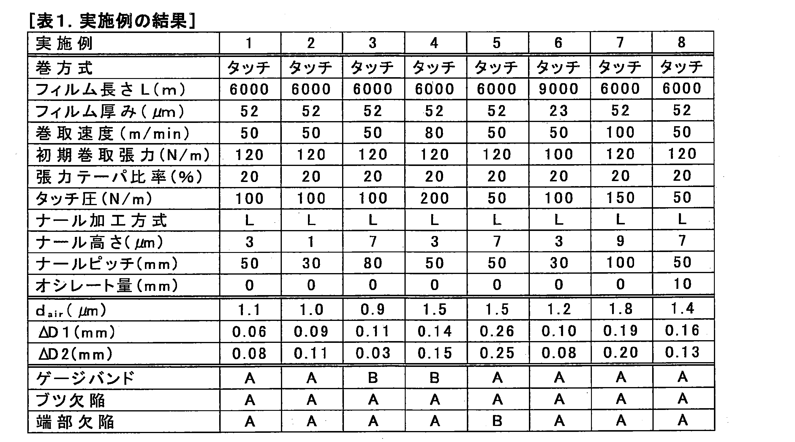

1 フィルムロール
2 フィルムロール
10 巻芯
10A 巻芯の中心軸
10S 巻芯の周面
100 長尺フィルム
100U 長尺フィルムの面
110L、110R ナール領域
111L、111R ナール部
112L、112R 間隔部
120 平坦領域
130 凹凸部
131 凹部
132 凸部
133 角部
134、135 直線部
140L、140R 縁
210L 第一大径部
210R 第二大径部
220 小径部
221L、221R 小径部内の測定範囲
230 境界部分
300L、300R レーザー変位計
310L、310R レーザー光の光軸
400 加工前フィルム
410 加工装置
411 レーザー光
420 搬送ロール
430 タッチロール
500 長尺フィルム
2 フィルムロール
10 巻芯
10A 巻芯の中心軸
10S 巻芯の周面
100 長尺フィルム
100U 長尺フィルムの面
110L、110R ナール領域
111L、111R ナール部
112L、112R 間隔部
120 平坦領域
130 凹凸部
131 凹部
132 凸部
133 角部
134、135 直線部
140L、140R 縁
210L 第一大径部
210R 第二大径部
220 小径部
221L、221R 小径部内の測定範囲
230 境界部分
300L、300R レーザー変位計
310L、310R レーザー光の光軸
400 加工前フィルム
410 加工装置
411 レーザー光
420 搬送ロール
430 タッチロール
500 長尺フィルム
Claims (14)
- 巻芯と、前記巻芯に巻き取られた長尺フィルムと、を有するフィルムロールであって;
前記長尺フィルムが、フィルム幅方向の両端部に設けられ複数の凸部を含む2つのナール領域と、前記2つのナール領域の間に設けられた平坦領域と、を含み;
前記フィルムロールが、前記長尺フィルムの前記ナール領域が巻き取られた2つの大径部と、前記2つの大径部の間に設けられ前記長尺フィルムの前記平坦領域が巻き取られた小径部と、を含み;
下記式(1)で表される第一巻径差ΔD1、及び、下記式(2)で表される第二巻径差ΔD2の両方が、0.3mmより小さく、
前記第一巻径差ΔD1及び前記第二巻径差ΔD2の少なくとも一方が、0.05mm以上であり;
前記フィルムロールのロール軸方向の中央において巻き取られた前記長尺フィルム間の空気層厚みが、0.9μm以上、2.0μm以下である、フィルムロール。

式(2)において、DN2(MAX)は、前記フィルムロールの前記2つの大径部の他方の直径の最大値を表し、DF2(AVE)は、前記フィルムロールの前記他方の大径部側の前記小径部の直径の平均値を表す。) - 前記長尺フィルムの前記ナール領域が、前記凸部を有するナール部と、前記凸部を有さない間隔部と、をフィルム長手方向において交互に含み;
フィルム長手方向における前記ナール部のピッチが、20mm以上、100mm以下である、請求項1に記載のフィルムロール。 - 前記凸部の高さが、1μm以上、10μm以下である、請求項1に記載のフィルムロール。
- 前記長尺フィルムが、シクロオレフィン重合体を含む、請求項1に記載のフィルムロール。
- 前記長尺フィルムの長さが、2000m以上、10000m以下である、請求項1に記載のフィルムロール。
- 巻芯と、前記巻芯に巻き取られた長尺フィルムと、を有するフィルムロールの製造方法であって;
前記長尺フィルムが、フィルム幅方向の両端部に設けられ複数の凸部を含む2つのナール領域と、前記2つのナール領域の間に設けられた平坦領域と、を含み;
前記長尺フィルムの前記ナール領域が、前記凸部を有するナール部と、前記凸部を有さない間隔部と、をフィルム長手方向において交互に含み;
フィルム長手方向における前記ナール部のピッチが、20mm以上、100mm以下であり;
前記製造方法が、
前記長尺フィルムをタッチロールに巻き掛ける工程と、
前記タッチロールを前記長尺フィルムの前記ナール領域に接触させながら、前記タッチロールに巻き掛けられた前記長尺フィルムを前記巻芯に巻き取る工程と、
を含む、フィルムロールの製造方法。 - 加工前フィルムに前記ナール部を形成して前記長尺フィルムを得る工程を含む、請求項6に記載のフィルムロールの製造方法。
- レーザー光の照射によって前記ナール部を形成することを含む、請求項7に記載のフィルムロールの製造方法。
- 前記加工前フィルムに前記ナール部を形成する工程が、前記ナール部の形成位置をフィルム幅方向においてオシレートさせることを含み;
前記ナール部1つの幅に対する前記ナール部のオシレート量の比が、0.5以上1.0以下である、請求項7に記載のフィルムロールの製造方法。 - 前記凸部の高さが、1μm以上、10μm以下である、請求項6に記載のフィルムロールの製造方法。
- 前記長尺フィルムが、シクロオレフィン重合体を含む、請求項6に記載のフィルムロールの製造方法。
- 巻き取られる前記長尺フィルムの長さが、2000m以上、10000m以下である、請求項6に記載のフィルムロールの製造方法。
- 前記タッチロールの軸方向長さが、前記長尺フィルムの幅以上であり、
前記長尺フィルムを前記巻芯に巻き取る工程において、前記タッチロールが、製造途中の前記フィルムロールを、前記巻芯の中心に向かって50N/m~200N/mの荷重で押している、請求項6に記載のフィルムロールの製造方法。 - 前記長尺フィルムのフィルム巻取速度が、10m/min以上、150m/min以下である、請求項6に記載のフィルムロールの製造方法。
Applications Claiming Priority (2)
| Application Number | Priority Date | Filing Date | Title |
|---|---|---|---|
| JP2023-202485 | 2023-11-30 | ||
| JP2023202485 | 2023-11-30 |
Publications (1)
| Publication Number | Publication Date |
|---|---|
| WO2025115641A1 true WO2025115641A1 (ja) | 2025-06-05 |
Family
ID=95897744
Family Applications (1)
| Application Number | Title | Priority Date | Filing Date |
|---|---|---|---|
| PCT/JP2024/040573 Pending WO2025115641A1 (ja) | 2023-11-30 | 2024-11-15 | フィルムロール及びその製造方法 |
Country Status (2)
| Country | Link |
|---|---|
| TW (1) | TW202537914A (ja) |
| WO (1) | WO2025115641A1 (ja) |
Citations (3)
| Publication number | Priority date | Publication date | Assignee | Title |
|---|---|---|---|---|
| JP2016132537A (ja) * | 2015-01-20 | 2016-07-25 | 日本ゼオン株式会社 | フィルムロールの製造方法及びフィルムロール |
| JP2017056648A (ja) * | 2015-09-17 | 2017-03-23 | 東レ株式会社 | 中間製品ロール |
| JP2023015895A (ja) * | 2021-07-20 | 2023-02-01 | 日本ゼオン株式会社 | フィルムロール及びその製造方法 |
-
2024
- 2024-11-15 WO PCT/JP2024/040573 patent/WO2025115641A1/ja active Pending
- 2024-11-22 TW TW113145024A patent/TW202537914A/zh unknown
Patent Citations (3)
| Publication number | Priority date | Publication date | Assignee | Title |
|---|---|---|---|---|
| JP2016132537A (ja) * | 2015-01-20 | 2016-07-25 | 日本ゼオン株式会社 | フィルムロールの製造方法及びフィルムロール |
| JP2017056648A (ja) * | 2015-09-17 | 2017-03-23 | 東レ株式会社 | 中間製品ロール |
| JP2023015895A (ja) * | 2021-07-20 | 2023-02-01 | 日本ゼオン株式会社 | フィルムロール及びその製造方法 |
Also Published As
| Publication number | Publication date |
|---|---|
| TW202537914A (zh) | 2025-10-01 |
Similar Documents
| Publication | Publication Date | Title |
|---|---|---|
| KR102157058B1 (ko) | 이형용 2축 배향 폴리에스테르 필름 | |
| JP7652215B2 (ja) | 二軸配向ポリエステルフィルムロール | |
| JP6451338B2 (ja) | フィルムロールの製造方法 | |
| TWI750376B (zh) | 薄膜輥及其製造方法 | |
| JP7802713B2 (ja) | 基材間のインターリーフとして使用されるフィルム | |
| TWI411850B (zh) | Optical sheet and its manufacturing method | |
| JP5522544B2 (ja) | 樹脂フィルムロールおよびその製造方法 | |
| JP7694221B2 (ja) | フィルムロール及びその製造方法 | |
| KR20110061592A (ko) | 광학 시트 및 액정표시장치용 면광원 | |
| TW202537914A (zh) | 薄膜卷及其製造方法 | |
| JP2021134007A (ja) | フィルムロールの製造方法及び製造装置 | |
| JP2017043493A (ja) | フィルムロールの製造方法 | |
| JP2010253696A (ja) | エンボス転写用熱可塑性樹脂シート、熱可塑性樹脂製エンボスシート、および、熱可塑性樹脂製エンボスシートの製造方法 | |
| EP3914445B1 (en) | Film for use as interleaf between substrates, method for manufacturing, use and stack of substrates | |
| JP2013237256A (ja) | 熱可塑性樹脂フィルム | |
| JP7830965B2 (ja) | フィルムロールの製造方法 | |
| JP7816152B2 (ja) | 長尺フィルム | |
| TW202108381A (zh) | 多層薄膜及其製造方法,以及捲繞體 | |
| JP2007070514A (ja) | 熱可塑性樹脂フィルムロール | |
| JP7815686B2 (ja) | 複層延伸フィルムの製造方法 | |
| KR0158734B1 (ko) | 폴리에스테르 필름 및 이의 제조방법 | |
| WO2020241692A1 (ja) | 二軸配向ポリエステルフィルム | |
| KR102753580B1 (ko) | 박리 필름 롤, 세라믹 부품 시트 및 그 제조 방법과 세라믹 부품 및 그 제조 방법 | |
| JP2009149420A (ja) | シート状物の巻取用巻芯体 | |
| JP2017030209A (ja) | 巻回体及びその製造方法、並びに、巻回体収納物及びその製造方法 |
Legal Events
| Date | Code | Title | Description |
|---|---|---|---|
| 121 | Ep: the epo has been informed by wipo that ep was designated in this application |
Ref document number: 24897328 Country of ref document: EP Kind code of ref document: A1 |
|
| ENP | Entry into the national phase |
Ref document number: 2025560997 Country of ref document: JP Kind code of ref document: A |