WO2025110221A1 - 車両の制動制御装置 - Google Patents
車両の制動制御装置 Download PDFInfo
- Publication number
- WO2025110221A1 WO2025110221A1 PCT/JP2024/041347 JP2024041347W WO2025110221A1 WO 2025110221 A1 WO2025110221 A1 WO 2025110221A1 JP 2024041347 W JP2024041347 W JP 2024041347W WO 2025110221 A1 WO2025110221 A1 WO 2025110221A1
- Authority
- WO
- WIPO (PCT)
- Prior art keywords
- pressure
- wheel
- target
- fluid
- control
- Prior art date
- Legal status (The legal status is an assumption and is not a legal conclusion. Google has not performed a legal analysis and makes no representation as to the accuracy of the status listed.)
- Pending
Links
Images



Classifications
-
- B—PERFORMING OPERATIONS; TRANSPORTING
- B60—VEHICLES IN GENERAL
- B60T—VEHICLE BRAKE CONTROL SYSTEMS OR PARTS THEREOF; BRAKE CONTROL SYSTEMS OR PARTS THEREOF, IN GENERAL; ARRANGEMENT OF BRAKING ELEMENTS ON VEHICLES IN GENERAL; PORTABLE DEVICES FOR PREVENTING UNWANTED MOVEMENT OF VEHICLES; VEHICLE MODIFICATIONS TO FACILITATE COOLING OF BRAKES
- B60T13/00—Transmitting braking action from initiating means to ultimate brake actuator with power assistance or drive; Brake systems incorporating such transmitting means, e.g. air-pressure brake systems
- B60T13/10—Transmitting braking action from initiating means to ultimate brake actuator with power assistance or drive; Brake systems incorporating such transmitting means, e.g. air-pressure brake systems with fluid assistance, drive, or release
- B60T13/12—Transmitting braking action from initiating means to ultimate brake actuator with power assistance or drive; Brake systems incorporating such transmitting means, e.g. air-pressure brake systems with fluid assistance, drive, or release the fluid being liquid
- B60T13/14—Transmitting braking action from initiating means to ultimate brake actuator with power assistance or drive; Brake systems incorporating such transmitting means, e.g. air-pressure brake systems with fluid assistance, drive, or release the fluid being liquid using accumulators or reservoirs fed by pumps
- B60T13/142—Systems with master cylinder
- B60T13/147—In combination with distributor valve
-
- B—PERFORMING OPERATIONS; TRANSPORTING
- B60—VEHICLES IN GENERAL
- B60T—VEHICLE BRAKE CONTROL SYSTEMS OR PARTS THEREOF; BRAKE CONTROL SYSTEMS OR PARTS THEREOF, IN GENERAL; ARRANGEMENT OF BRAKING ELEMENTS ON VEHICLES IN GENERAL; PORTABLE DEVICES FOR PREVENTING UNWANTED MOVEMENT OF VEHICLES; VEHICLE MODIFICATIONS TO FACILITATE COOLING OF BRAKES
- B60T13/00—Transmitting braking action from initiating means to ultimate brake actuator with power assistance or drive; Brake systems incorporating such transmitting means, e.g. air-pressure brake systems
- B60T13/10—Transmitting braking action from initiating means to ultimate brake actuator with power assistance or drive; Brake systems incorporating such transmitting means, e.g. air-pressure brake systems with fluid assistance, drive, or release
- B60T13/12—Transmitting braking action from initiating means to ultimate brake actuator with power assistance or drive; Brake systems incorporating such transmitting means, e.g. air-pressure brake systems with fluid assistance, drive, or release the fluid being liquid
- B60T13/14—Transmitting braking action from initiating means to ultimate brake actuator with power assistance or drive; Brake systems incorporating such transmitting means, e.g. air-pressure brake systems with fluid assistance, drive, or release the fluid being liquid using accumulators or reservoirs fed by pumps
- B60T13/148—Arrangements for pressure supply
-
- B—PERFORMING OPERATIONS; TRANSPORTING
- B60—VEHICLES IN GENERAL
- B60T—VEHICLE BRAKE CONTROL SYSTEMS OR PARTS THEREOF; BRAKE CONTROL SYSTEMS OR PARTS THEREOF, IN GENERAL; ARRANGEMENT OF BRAKING ELEMENTS ON VEHICLES IN GENERAL; PORTABLE DEVICES FOR PREVENTING UNWANTED MOVEMENT OF VEHICLES; VEHICLE MODIFICATIONS TO FACILITATE COOLING OF BRAKES
- B60T8/00—Arrangements for adjusting wheel-braking force to meet varying vehicular or ground-surface conditions, e.g. limiting or varying distribution of braking force
- B60T8/17—Using electrical or electronic regulation means to control braking
Definitions
- This disclosure relates to a vehicle braking control device.
- Patent document 1 describes a vehicle brake device that includes an electric hydraulic pressure generating means (23) that generates brake hydraulic pressure by operating an electric motor (32) and an electric motor control means (U) that controls the operation of the electric motor (32) in order to maintain a constant relationship between the rotation angle and the generated brake hydraulic pressure when the brake hydraulic pressure generated by the electric hydraulic pressure generating means is controlled by feedback of the rotation angle of the electric motor, the electric motor control means (U) calculates a target rotation angle of the electric motor (32) for causing the electric hydraulic pressure generating means (23) to generate brake hydraulic pressure corresponding to the amount of brake operation by the driver, and feedback controls the actual rotation angle of the electric motor (32) to match the target rotation angle, and the electric motor control means (U) includes a correction means (M5) that corrects the target rotation angle of the electric motor (32) based on the actual brake hydraulic pressure generated by the electric hydraulic pressure generating means (23).
- M5 correction means
- the correction means M5 calculates a hydraulic pressure correction amount converted into the rotation angle of the electric motor 32 (also called the “electric motor”) based on the deviation between the target brake hydraulic pressure output by the subtraction means M4 and the actual brake hydraulic pressure (also called the “hydraulic pressure deviation").
- the hydraulic pressure deviation is converted into the rotation angle of the electric motor.
- This conversion is affected by the nonlinear characteristics of the hydraulic pressure (also called “wheel pressure") generated in the wheel cylinder. Specifically, even if the same hydraulic pressure deviation occurs, when the wheel pressure is low, the rotation angle of the electric motor needs to be larger than when the wheel pressure is high.
- the object of the present invention is to provide a vehicle braking control device that adjusts wheel pressure using an electric motor and that can take into account the nonlinear characteristics of wheel pressure.
- the vehicle braking control device (SA) of the present invention comprises a control cylinder (CC) into which a control piston (NC) is inserted and which generates a servo pressure (Pa) by moving the control piston (NC) using an electric motor (MA), a servo pressure sensor (PA) which detects the servo pressure (Pa), and a controller (EA) which calculates a target pressure (Pt) based on a braking demand (Bs) and controls the electric motor (MA) based on the target pressure (Pt) and the servo pressure (Pa), and adjusts the wheel pressure (Pw) of the wheel cylinder (CW) using the servo pressure (Pa).
- the controller (EA) calculates the standard fluid volume (Es) that should flow into the wheel cylinder (CW) based on the target pressure (Pt), calculates the estimated fluid volume (Ee) that is assumed to have flowed into the wheel cylinder (CW) based on the servo pressure (Pa), and controls the electric motor (MA) based on the deviation (hE) between the estimated fluid volume (Ee) and the standard fluid volume (Es).
- the controller (EA) controls the rotation angle (Ka) of the electric motor (MA) based on the reference value (Ks) calculated from the standard fluid volume (Es) and the correction value (Kp) calculated from the deviation (hE).
- the controller (EA) also determines the standard fluid volume (Es) and the estimated fluid volume (Ee) based on a conversion map (Zef, Zer, Zek) that represents the relationship between the volume of the brake fluid (BF) in the wheel cylinder (CW) and the wheel pressure (Pw).
- FIG. 1 is a schematic diagram for explaining a first embodiment of a vehicle braking control device SA;
- FIG. 4 is a flow chart for explaining a pressure regulation control process.
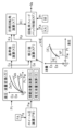
- FIG. 4 is a block diagram for explaining drive control of the electric cylinder DN.
- FIG. 2 is a schematic diagram for explaining a second embodiment of a vehicle braking control device SA.
- the vehicle is equipped with a regenerative device KG.
- the regenerative device KG is composed of a generator GN for energy regeneration (also called an “electric motor/generator” or “regenerative generator”), a control unit EG for the regenerative device KG (also called a “regenerative controller”), and a regenerative storage battery (not shown).
- the regenerative generator GN also serves as an electric motor for driving.
- the electric motor/generator GN operates as a generator, and the generated electric power is stored in the regenerative storage battery via the regenerative controller EG.
- a regenerative braking force Fg acts on the wheels. That is, the regenerative device KG can generate a regenerative braking force Fg.
- the regenerative device KG is provided on the front wheels WHf. Therefore, the regenerative braking force Fg is generated on the front wheels WHf.
- the regenerative device KG (particularly, the regenerative controller EG) is connected to the communication bus BS.
- the vehicle is equipped with a driving assistance device KJ.
- the driving assistance device KJ executes automatic speed control.
- the driving assistance device KJ is composed of an object detection sensor SJ and a driving assistance controller EJ (also simply referred to as a “driving assistance controller”).
- the object detection sensor SJ detects a distance Sj (called the "relative distance”, and also called the “inter-vehicle distance" when the object is a preceding vehicle) to an object present in front of the vehicle (including a preceding vehicle traveling in front of the vehicle).
- a radar sensor, a millimeter wave sensor, an image sensor, etc. are used as the object detection sensor SJ.
- the driving assistance controller EJ calculates the target acceleration Gs of the vehicle (the target value of the vehicle body acceleration in the longitudinal direction of the vehicle) based on the detection result Sj (relative distance) of the object detection sensor SJ.
- the driving assistance device KJ (particularly, the driving assistance controller EJ) is connected to a communication bus BS.
- the target acceleration Gs is transmitted to the brake control device SA via the communication bus BS.
- the brake control device SA the braking forces Fg and Fe are adjusted according to the target acceleration Gs.
- the vehicle's traveling speed Vx (vehicle speed) is controlled.
- the vehicle is equipped with a brake operating member BP and various sensors (SP, etc.).
- the brake operating member BP e.g., a brake pedal
- the vehicle is provided with an operating displacement sensor SP that detects the operating displacement Sp of the brake operating member BP.
- the operating displacement Sp is one of the state quantities (state variables) that indicate the operating amount of the brake operating member BP, and in a brake-by-wire type brake control device SA, it is a signal that indicates the driver's intention to brake (i.e., a braking instruction).
- each wheel WH is equipped with various sensors for braking control (i.e., individual control of each wheel pressure Pw), such as anti-lock brake control and anti-skid control.
- each wheel WH is equipped with a wheel speed sensor VW that detects its rotational speed Vw (called “wheel speed”).
- a steering amount sensor that detects the steering amount Sw (e.g., the steering angle) of a steering operation member (e.g., the steering wheel), a yaw rate sensor that detects the yaw rate Yr of the vehicle, a longitudinal acceleration sensor that detects the longitudinal acceleration Gx of the vehicle (also called “deceleration”), and a lateral acceleration sensor that detects the lateral acceleration Gy of the vehicle (all not shown).
- the vehicle is equipped with a brake control device SA.
- the brake control device SA uses a so-called front and rear type (also called "type II") brake system as the two-system brake system.
- the brake control device SA adjusts the wheel pressure Pw of each wheel cylinder CW.
- the brake control device SA (particularly, the brake controller EA) and the hydraulic pressure correction device SZ (particularly, the correction controller EZ) are connected to a communication bus BS. Signals are transmitted between the multiple controllers (EA, EZ, EG, EJ, etc.) via the communication bus BS. In other words, the multiple controllers can send signals (detection values, calculation values, control flags, etc.) to the communication bus BS and can receive signals from the communication bus BS.
- the configuration of the brake control device SA according to the first embodiment will be described.
- the brake control device SA generates a servo pressure Pa in response to the operation of a brake operating member BP (brake pedal). Then, the brake control device SA outputs a supply pressure Pm and a servo pressure Pa to a hydraulic pressure correction device SZ.
- the hydraulic pressure correction device SZ adjusts the supply pressure Pm and the servo pressure Pa, and ultimately supplies front and rear wheel pressures Pwf and Pwr to the front and rear wheel cylinders CWf and CWr.
- the brake control device SA is composed of a brake actuator YA and a brake controller EA.
- the brake actuator YA is composed of a hydraulic pressure generating unit PU, an apply unit AP, and an input unit NR.
- the electric motor MA is a power source (pressurizing source) for generating the servo pressure Pa (hydraulic pressure generated by the electric cylinder DN).
- Power refers to the energy required to move the movable members (GS, GH, NC, etc.) in the electric cylinder DN.
- power is defined as a physical quantity, energy per unit time (also called “power”).
- Rotational power (also called “first rotational power”) is output from the electric motor MA.
- the rotational power of the electric motor MA is the shaft torque of the electric motor MA multiplied by the rotational speed of the electric motor MA (particularly the motor shaft).
- the linear power of the linearly moving member (described later) is the thrust of the linearly moving member (force acting in the direction of the central axis) multiplied by the linear speed of the linearly moving member (speed in the direction along the central axis).
- a three-phase brushless motor is used as the electric motor MA.
- the electric motor MA includes a motor coil, a motor shaft, and a rotation angle sensor KA.
- the motor coil is fixed to the motor housing.
- the controller EA (particularly the drive circuit DR) supplies power to the motor coil.
- the motor shaft is rotatably supported relative to the motor housing.
- a permanent magnet is fixed to the outer periphery of the motor shaft.
- the magnetic pole position of the permanent magnet i.e., the motor rotation angle Ka
- the rotation angle sensor KA also equivalent to a "liquid volume sensor"
- the three-phase motor current Im (a collective term for the currents flowing through the U, V, and W phases) relating to the U, V, and W phases is switched based on the rotation angle Ka of the motor shaft.
- a signal of the rotation angle Ka (which also corresponds to the "discharge liquid volume Ej (described later)" detected by the rotation angle sensor KA is transmitted to the controller EA (particularly the microprocessor MP).
- the controller EA drives the switching element of the drive circuit DR (also called the “inverter circuit") according to the rotation angle Ka. This switches the motor current Im flowing through the motor coil, and drives the electric motor MA.
- the first rotational power is then output from the electric motor MA to the reducer GS.
- the first rotational power output from the electric motor MA is reduced by the reducer GS.
- the input shaft of the reducer GS and the motor shaft are fixed.
- the output shaft of the reducer GS and the rotating member of the conversion mechanism GH are fixed.
- the reducer GS the speed input from the electric motor MA is reduced and the torque input from the electric motor MA is increased.
- the reduced rotational power (also called the "second rotational power") is then output from the reducer GS to the conversion mechanism GH.
- the conversion mechanism GH is composed of a rotating member that performs rotational motion, and a linear member that performs linear motion.
- the second rotational power output from the reducer GS is input to the rotating member.
- the rotational power input to the rotating member is then converted into linear power for the linear member.
- the conversion mechanism GH is also called the "rotation-linear conversion mechanism.”
- a rotation-stop member is engaged with the linear member. This prevents the rotational motion of the linear member, so that the linear member moves along the rotation axis of the rotating member.
- a "ball screw” is used as the conversion mechanism GH.
- a rotating member which is a shaft member, is fixed to the output shaft of the reducer GS.
- the rotating member is inserted into a linear motion member having a cylindrical shape.
- a ball screw groove is formed on the outer peripheral surface of the rotating member.
- a ball screw groove is also formed on the inner peripheral surface of the linear motion member. Multiple balls (steel balls) are fitted into the ball screw groove.
- the control piston NC is inserted into the control cylinder CC. Inside the control cylinder CC, the control piston NC forms a control chamber Rc (hydraulic pressure chamber). In detail, the outer peripheral surface of the control piston NC and the inner peripheral surface of the control cylinder CC are sealed by two seal members SL. This makes the control chamber Rc liquid-tight.
- the hydraulic pressure in the control cylinder CC i.e., the control chamber Rc
- the servo pressure Pa is the servo pressure Pa. That is, in the electric cylinder DN, the electric motor MA is used as the power source, and the servo pressure Pa is output.
- FIG. 1 shows a state in which the electric cylinder DN is not generating servo pressure Pa.
- the control cylinder CC has a through hole between two seal members SL.
- the control piston NC also has a through hole.
- a supply path HH (fluid path) connected to the master reservoir RV is connected to the through hole of the control cylinder CC.
- the control chamber Rc is connected to the master reservoir RV via the through hole and the supply path HH, and the servo pressure Pa is "0 (atmospheric pressure)".
- the position of the control piston NC in this state is called the "initial position". In the initial position, the control piston NC is displaced to its maximum in the backward direction Hb, and the volume of the control chamber Rc is maximum.
- Servo pressure Pa is supplied to the servo chamber Ru from the hydraulic pressure generating unit PU (electric cylinder DN).
- the servo pressure Pa causes the apply unit AP to output a supply pressure Pm.
- supply pressure Pm is the internal pressure of the master chamber Rm, and is also called “master pressure.”
- Pa 0
- the master piston NM is in the most retracted position (i.e., the position where the volume of the master chamber Rm is maximum). In this state, the master chamber Rm of the master cylinder CM is connected to the master reservoir RV. Therefore, the master pressure Pm is "0 (atmospheric pressure)."
- Brake fluid BF is stored inside the master reservoir RV (also called the "atmospheric pressure reservoir”).
- the master piston NM moves in the forward direction Da (the direction in which the volume of the master chamber Rm decreases). This movement blocks communication between the master chamber Rm and the master reservoir RV.
- the supply pressure Pm master pressure
- the supply pressure Pm master pressure
- the input unit NR realizes regenerative cooperative control.
- the "regenerative cooperative control” cooperates the frictional braking force Fe (braking force due to the wheel pressure Pw) and the regenerative braking force Fg (braking force due to the regenerative device KG) so that the kinetic energy of the vehicle can be efficiently recovered as electrical energy during braking.
- the brake operating member BP is operated, but a state is created in which the wheel pressure Pw is not generated.
- the input unit NR is composed of an input cylinder CN, an input piston NN, a first control valve VA, a second control valve VB, a stroke simulator SS, and an input pressure sensor PN.
- the input cylinder CN is fixed to the master cylinder CM.
- An input piston NN is inserted into the input cylinder CN.
- the input piston NN is mechanically connected to the brake operating member BP (brake pedal) so as to move in conjunction with the movement of the brake operating member BP.
- the separation distance Ln is adjusted by the servo pressure Pa, thereby achieving regenerative cooperative control.
- the input chamber Rn of the input unit NR is connected to the reaction chamber Rs of the apply unit AP via an input path HN (fluid path).
- a normally closed first control valve VA is provided in the input path HN.
- the input path HN is connected to the master reservoir RV between the first control valve VA and the reaction chamber Rs via a reservoir path HR (fluid path).
- a normally open second control valve VB is provided in the reservoir path HR.
- On-off type solenoid valves are used for the first and second control valves VA and VB.
- a stroke simulator SS is connected to the input path HN between the first control valve VA and the reaction chamber Rs.
- the first control valve VA When power is not supplied to the first and second control valves VA and VB, the first control valve VA is closed and the second control valve VB is open.
- the input chamber Rn When the first control valve VA is closed, the input chamber Rn is sealed and fluid locked. This causes the master piston NM to displace integrally with the brake operating member BP.
- the second control valve VB When the second control valve VB is open, the stroke simulator SS and the reaction chamber Rs are connected to the master reservoir RV.
- the first control valve VA When power is supplied to the first and second control valves VA, VB, the first control valve VA is opened and the second control valve VB is closed. This allows the master piston NM to be displaced separately from the brake operating member BP.
- the input chamber Rn is connected to the stroke simulator SS, so that the operating force of the brake operating member BP is generated by the stroke simulator SS.
- An input pressure sensor PN is provided in the input path HN between the input chamber Rn and the first control valve VA to detect the input pressure Pn.
- the input pressure Pn is also the hydraulic pressure inside the stroke simulator SS.
- the brake actuator YA is controlled by a brake controller EA.
- the brake controller EA is composed of a microprocessor MP and a drive circuit DR.
- the controller EA is connected to a communication bus BS so that signals (detection values, calculation values, control flags, etc.) can be shared between the controller EA and other controllers (EZ, EG, EJ, etc.).
- the brake controller EA directly receives various signals such as the operation displacement Sp (detection value of the operation displacement sensor SP), input pressure Pn (detection value of the input pressure sensor PN), servo pressure Pa (detection value of the servo pressure sensor PA), and motor rotation angle Ka (detection value of the rotation angle sensor KA).
- the controller EA receives various signals such as the supply pressure Pm, standard regenerative braking force Fz, vehicle speed Vx, and target acceleration Gs from the communication bus BS.
- the brake controller EA also outputs a target regenerative braking force Fh (target value of the regenerative braking force Fg) to the communication bus BS.
- the regenerative controller EG controls the regenerative braking force Fg (actual value) based on the target regenerative braking force Fh (target value) obtained from the communication bus BS.
- the braking controller EA (particularly the microprocessor MP) is programmed with a pressure regulation control algorithm.
- the drive circuit DR drives the electric motor MA and various solenoid valves (VA, etc.).
- the drive circuit DR includes an inverter circuit made of switching elements (e.g., MOS-FET) to drive the electric motor MA.
- the drive circuit DR also includes switching elements to drive the various solenoid valves.
- the drive circuit DR includes a motor current sensor (not shown) that detects the supply current Im (motor current) to the electric motor MA.
- the electric motor MA is provided with a rotation angle sensor KA to detect the position Ka (rotation angle) of the motor shaft.
- the braking controller EA calculates the drive signals Va, Vb for the first and second control valves VA, VB, and the drive signal Ma for the electric motor MA. Then, the switching elements are driven in response to the various drive signals (Ma, etc.). Specifically, in controlling the solenoid valves, power is supplied to the first and second control valves VA, VB based on the drive signals Va, Vb. This opens the first control valve VA and closes the second control valve VB.
- the drive signal Ma is determined based on the pressure regulation control algorithm, and the electric motor MA is controlled based on the drive signal Ma.
- a hydraulic pressure correction device SZ is provided between the brake control device SA and the wheel cylinder CW. Antilock brake control, traction control, anti-skid control, etc. are performed by the hydraulic pressure correction device SZ.
- a supply pressure Pm is supplied from a master cylinder CM to the hydraulic pressure correction device SZ.
- a servo pressure Pa is directly supplied from a hydraulic pressure generating unit PU to the hydraulic pressure correction device SZ.
- the supply pressure Pm and the servo pressure Pa are adjusted (increased or decreased) by the hydraulic pressure correction device SZ, and are output as hydraulic pressures Pwf, Pwr (front and rear wheel pressures) of the front and rear wheel cylinders CWf, CWr.
- the hydraulic pressure correction device SZ is composed of a correction actuator YZ and a correction controller EZ.
- the configuration of the correction actuator YZ is publicly known, so a description thereof will be omitted.
- the correction actuator YZ is provided with a supply pressure sensor PM to detect the supply pressure Pm.
- the servo pressure Pa is transmitted as the supply pressure Pm via the master piston NM. Therefore, the supply pressure Pm corresponds to the servo pressure Pa, and the supply pressure sensor PM corresponds to the servo pressure sensor PA.
- the supply pressure Pm is an example of the servo pressure Pa
- the supply pressure sensor PM is an example of the servo pressure sensor PA.
- a regenerative cooperative control between the regenerative device KG and the brake control device SA is executed.
- the regenerative braking force Fg and the friction braking force Fe are adjusted to cooperate with each other, and a total braking force Fu according to the required braking amount Bs is achieved.
- Total braking force Fu is the actual braking force acting on the entire vehicle.
- a target value corresponding to the total braking force Fu is “target total braking force Fv.”
- Friction braking force Fe (hydraulic braking force) is the braking force actually generated by the wheel pressure Pw.
- a target value corresponding to the friction braking force Fe is the “target friction braking force Fn.”
- Regenerative braking force Fg is the braking force actually generated by the regenerative device KG.
- a target value corresponding to the regenerative braking force Fg is the "target regenerative braking force Fh”.
- the target regenerative braking force Fh is calculated by the braking control device SA (particularly, the braking controller EA) and transmitted to the regenerative device KG (particularly, the regenerative controller EG) via the communication bus BS.
- the regenerative controller EG controls the generator GN so that the actual regenerative braking force Fg approaches and coincides with the target regenerative braking force Fh.
- the standard regenerative braking force Fz is calculated by the regenerative device KG (particularly, the regenerative controller EG) and transmitted to the brake control device SA (particularly, the brake controller EA) via the communication bus BS.
- the standard regenerative braking force Fz can be limited depending on the driving conditions of the vehicle (for example, the friction coefficient of the road).
- Servo pressure Pa is the output of the electric cylinder DN (i.e., the internal pressure of the control chamber Rc).
- the servo pressure Pa is detected (acquired) by the servo pressure sensor PA.
- Target pressure Pt corresponds to a target value for controlling the servo pressure Pa (actual value).
- the hydraulic pressure transmission in the brake control device SA involves various resistances, such as pipe friction resistance in the fluid path, resistance as the solenoid valve orifice, and sliding resistance of the seal member SL.
- the actual value is controlled to match the target value, but taking the above resistance into consideration, it is desirable to compare the actual value with the target value at the same location. In the following explanation, this comparison is performed at the wheel cylinder CW. That is, the target pressure Pt is determined to correspond to the wheel pressure Pw. The wheel pressure Pw (actual value) is then determined from the servo pressure Pa (detection value of the servo pressure sensor PA) with the hydraulic pressure equivalent to the above resistance compensated for.
- first power is supplied to the first and second control valves VA, VB.
- the normally closed first control valve VA is opened, and the normally open second control valve VB is closed.
- the operating force of the brake operating member BP is generated by the stroke simulator SS.
- step S110 various signals are read in the brake controller EA.
- the brake controller EA acquires the braking operation amount Ba (generic term for Sp and Pn), the target acceleration Gs, the servo pressure Pa, and the standard regenerative braking force Fz.
- the braking operation amount Ba and the target acceleration Gs are collectively referred to as the "braking demand amount Bs.”
- the braking demand amount Bs is a state amount that represents the braking demand for the vehicle.
- the servo pressure Pa is acquired by at least one of the servo pressure sensor PA and the supply pressure sensor PM.
- the standard regenerative braking force Fz is determined by the regenerative device KG (particularly the regenerative controller EG) and is received by the brake controller EA via the communication bus BS.
- step S120 the target total braking force Fv (the target value of the total braking force Fu acting on the entire vehicle) is calculated based on the braking demand Bs and the calculation map Zfv.
- the target total braking force Fv is calculated to be "0" according to the calculation map Zfv.
- the target total braking force Fv is calculated to increase from "0" as the braking demand Bs increases.
- the "predetermined amount bo” is preset as a predetermined value (constant) (see target total braking force calculation block FV).
- step S130 the target pressure Pt is calculated based on the target total braking force Fv and the standard regenerative braking force Fz so that regenerative cooperative control is performed.
- the "target pressure Pt” is the target value of the wheel pressure Pw, and is the target value for controlling the servo pressure Pa.
- step S130 first, the sum Fnt (also called the “target sum") of the target regenerative braking force Fh and the target frictional braking force Fn is calculated.
- the target pressure Pt is then determined for the following two cases:
- the “specifications of the braking device SX” include the pressure-receiving area of the wheel cylinder CW, the effective braking radius of the rotating member KT (brake disc), the friction coefficient of the friction member (brake pad), and the effective radius of the wheel WH.
- the servo pressure Pa is transmitted to the front wheel cylinder CWf via the master cylinder CM and the master piston NM, so that the sliding resistance of the seal member SL can be taken into account in the calculation of the target pressure Pt.
- step S140 the electric motor MA is controlled based on the target pressure Pt. Specifically, first, the wheel pressure Pw is calculated from the servo pressure Pa, taking into account the resistance in the hydraulic pressure transmission path (such as the sliding resistance of the seal member SL).
- the servo pressure Pa is acquired by at least one of the servo pressure sensor PA and the supply pressure sensor PM. Then, by driving the electric cylinder DN (particularly the electric motor MA), the servo pressure Pa is controlled so that the wheel pressure Pw (calculated actual value) approaches and matches the target pressure Pt (target value).
- the wheel pressure Pw is calculated in the wheel pressure calculation block PW based on the servo pressure Pa. As described above, the target pressure Pt is determined to correspond to the wheel pressure Pw. Therefore, the wheel pressure Pw is determined from the servo pressure Pa based on the resistance in the hydraulic pressure transmission path.
- the hydraulic pressure to fluid volume conversion block ZE converts (converts) hydraulic pressure to fluid volume.
- Hydraulic pressure is the pressure in the wheel cylinder CW
- fluid volume is the volume of brake fluid BF in the wheel cylinder CW.
- the fluid volume conversion block ZE has front and rear wheel conversion maps Zef and Zer (corresponding to “conversion maps”).
- the conversion maps Zef and Zer express the relationship between the hydraulic pressure Pw generated in the wheel cylinder CW and the volume of brake fluid BF in the wheel cylinder CW (also called “hydraulic pressure-fluid volume characteristics").
- the front and rear wheel conversion maps Zef and Zer are obtained in advance through experiments, analysis, etc., and are stored in the controller EA.
- the hydraulic pressure-fluid volume characteristic (nonlinear characteristic of wheel pressure Pw)
- a larger volume of fluid is required to generate the wheel pressure Pw compared to when the wheel pressure Pw is large.
- a smaller volume of fluid can generate the wheel pressure Pw compared to when the wheel pressure Pw is small.
- the volume of fluid increases in an "upwardly convex" manner as the wheel pressure Pw increases.
- the hydraulic pressure/fluid volume conversion block ZE includes a standard fluid volume calculation block ES and an estimated fluid volume calculation block EE.
- a standard fluid volume Es is calculated based on the target pressure Pt and the front and rear wheel conversion maps Zef and Zer.
- the "standard fluid volume Es" is the amount (volume) of brake fluid BF that should flow into the front wheel cylinder CWf and the rear wheel cylinder CWr to achieve the target pressure Pt.
- the standard fluid volume Es is the target value for the amount of fluid that should be supplied from the control cylinder CC to the wheel cylinder CW.
- the standard fluid volume calculation block ES calculates the front wheel standard fluid volume Esf based on the target pressure Pt and the front wheel conversion map Zef.
- the "front wheel standard fluid volume Esf” is the volume of fluid (volume of brake fluid BF) that should flow into the front wheel cylinder CWf to achieve the target pressure Pt.
- the standard fluid volume calculation block ES calculates the rear wheel standard fluid volume Esr based on the target pressure Pt and the rear wheel conversion map Zer.
- the "rear wheel standard fluid volume Esr” is the volume of fluid that should flow into the rear wheel cylinder CWr to achieve the target pressure Pt.
- the standard fluid volume Es is the sum of the front wheel standard fluid volume Esf and the rear wheel standard fluid volume Esr.
- an estimated fluid volume Ee is calculated based on the wheel pressure Pw and the front and rear wheel conversion maps Zef and Zer.
- the "estimated fluid volume Ee" is the amount (volume) of brake fluid BF that should already have been supplied to the front wheel cylinder CWf and the rear wheel cylinder CWr in order to generate the wheel pressure Pw.
- the front wheel estimated fluid volume Eef is calculated based on the wheel pressure Pw and the front wheel conversion map Zef (i.e., the hydraulic pressure-fluid volume characteristics of the front wheel cylinder CWf).
- the rear wheel estimated fluid volume Eer is calculated based on the rear wheel pressure Pw and the rear wheel conversion map Zer (i.e., the hydraulic pressure-fluid volume characteristics of the rear wheel cylinder CWr).
- the estimated fluid volume Ee is the sum of the front wheel estimated fluid volume Eef and the rear wheel estimated fluid volume Eer, and is the volume of fluid estimated to have flowed from the control cylinder CC to the wheel cylinder CW. Note that since the wheel pressure Pw is derived from the servo pressure Pa, it can be said that "the estimated fluid volume Ee is calculated based on the servo pressure Pa and the front and rear wheel conversion maps Zef and Zer.”
- the "reference value Ks" is a state quantity (variable) for determining a target value for controlling the electric motor MA.
- the reference value Ks is a state variable obtained by converting the standard liquid volume Es into a dimension (i.e., a physical quantity) from the standard liquid volume Es to the rotation angle of the electric motor MA.
- the dimension (physical quantity) of the reference value Ks any one of the dimensions of the liquid volume, the dimension of the displacement of the control piston NC, and the dimension of the rotation angle of the electric motor MA can be adopted.
- the electric cylinder DN the specifications of the components are known.
- a correction value Kp is calculated based on the standard fluid volume Es and the estimated fluid volume Ee.
- a fluid volume deviation hE is calculated from the standard fluid volume Es and the estimated fluid volume Ee.
- the "fluid volume deviation hE" is the difference between the standard fluid volume Es and the estimated fluid volume Ee, and is the difference between the fluid volume Es (standard fluid volume) that should be supplied to the wheel cylinder CW to achieve the target pressure Pt and the fluid volume Ee (estimated fluid volume) that actually flows into the wheel cylinder CW.
- the correction value Kp is a state quantity for making the servo pressure Pa coincide with the target pressure Pt.
- the correction of the reference value Ks based on the correction value Kp corresponds to feedback control of the amount of brake fluid BF. That is, closed-loop control is executed so that the estimated fluid amount Ee (actual value) approaches and coincides with the standard fluid amount Es (target value).
- the correction using the correction value Kp also functions as feedback control of the fluid pressure.
- the brake control device SA feedback control based on the correction value Kp is used to control the servo pressure Pa to approach and coincide with the target pressure Pa, taking into account the nonlinearity of the wheel pressure Pw.
- the target rotation angle Kt is calculated based on the command value Ku.
- the command value Ku is converted into the dimension (physical quantity) of the motor rotation angle Ka using the specifications of the components of the electric cylinder DN (reduction ratio of the reducer GS, lead of the conversion mechanism GH, etc.), and the target rotation angle Kt is determined.
- the responsiveness of the electric motor MA can be taken into consideration. For example, a limit is imposed on the response speed (i.e., the amount of change per unit time) of the target rotation angle Kt through a response model of the electric motor MA.
- the target rotation angle Kt which is the final target value, is determined based on the reference value Ks and the correction value Kp.
- the electric motor MA is controlled in the rotation angle feedback control block KF based on the target rotation angle Kt and the actual motor rotation angle Ka. Specifically, the drive signal Ma of the electric motor MA is determined so that the motor rotation angle Ka (actual value) acquired by the rotation angle sensor KA approaches and matches the target rotation angle Kt (target value) (i.e., so that the deviation hK between the target value Kt and the actual value Ka approaches "0"). Then, in the drive circuit DR (inverter circuit), the current Im (motor current) supplied to the electric motor MA is adjusted based on the motor drive signal Ma. That is, the rotation angle feedback control block KF executes what is called rotation angle feedback control.
- the drive circuit DR inverter circuit
- the standard fluid volume calculation block ES and the estimated fluid volume calculation block EE are provided with the front wheel conversion map Zef and the rear wheel conversion map Zer as calculation maps for converting the hydraulic pressure to the hydraulic volume.
- the front wheel standard fluid volume Esf and the rear wheel standard fluid volume Esr are calculated separately, and the front wheel estimated fluid volume Eef and the rear wheel estimated fluid volume Eer are determined separately.
- a conversion map Zek also called an "integrated conversion map” in which the front and rear wheel conversion maps Zef and Zer are integrated may be used as a calculation map for converting the hydraulic pressure to the hydraulic volume (see the characteristics shown by the dashed line).
- the integrated conversion map Zek also specifies the relationship between the hydraulic pressure and the hydraulic volume.
- the reference value Ks is determined based on the target pressure Pt and the standard fluid volume Es calculated from the integrated conversion map Zek.
- the correction value Kh is determined based on the servo pressure Pa (i.e., the wheel pressure Pw) and the estimated fluid volume Ee calculated from the integrated conversion map Zek.
- the integrated conversion map Zek is also obtained in advance by experiment, analysis, etc., like the front and rear wheel conversion maps Zef and Zer.
- the electric motor MA is controlled based on the difference hE (fluid volume deviation) between the standard fluid volume Es and the estimated fluid volume Ee, not the difference hP (fluid pressure deviation) between the target pressure Pt and the wheel pressure Pw.
- the blowout section XHE illustrates a situation in which the wheel pressure Pw is insufficient for the target pressure Pt by the fluid pressure deviation hP.
- the characteristic (A) indicates the fluid pressure-fluid volume characteristic in the wheel cylinder CW (i.e., the nonlinear characteristic of the wheel pressure Pw).
- the fluid pressure-fluid volume characteristic (A) is taken into account by the conversion maps Zef, Zer, and Zek.
- the amount of fluid supplied to the wheel cylinder CW is insufficient by the hydraulic volume deviation hE.
- the amount of fluid supplied to the wheel cylinder CW is in excess by the hydraulic volume deviation hE (not shown).
- the amount of fluid (volume) discharged from the electric cylinder DN is proportional to the rotation angle Ka of the electric motor MA. Therefore, the relationship between the motor rotation angle Ka and the wheel pressure Pw is nonlinear. In contrast, the relationship between the motor rotation angle Ka and the hydraulic volume is linear.
- the brake control device SA does not use the hydraulic pressure deviation hP, but uses the hydraulic volume deviation hE. Since the conversion maps Zef, Zer, and Zek are taken into account in the calculation of the hydraulic volume deviation hE, the nonlinear characteristics of the wheel pressure Pw can be appropriately taken into account in the control of the electric motor MA.
- ⁇ Second embodiment of the brake control device SA> A second embodiment of the vehicle brake control device SA will be described with reference to the schematic diagram of Fig. 4.
- the electric motor MA of the electric cylinder DN is controlled in the same manner as in the first embodiment.
- the servo pressure Pa is transmitted as the supply pressure Pm via the master cylinder CM and the master piston NM. That is, the apply unit AP and the hydraulic pressure generating unit PU are arranged in series in the hydraulic pressure transmission path. Alternatively, the apply unit AP and the hydraulic pressure generating unit PU may be arranged in parallel. In the second embodiment, the apply unit AP (particularly, the master cylinder CM) and the hydraulic pressure generating unit PU are each directly connected to the hydraulic pressure correction device SZ (particularly, the correction actuator YZ).
- a shutoff valve VM is a normally open on-off solenoid valve
- the simulator valve VS and the communication valve VC are normally closed on-off solenoid valves.
- the shutoff valve VM is provided in the front wheel communication passage HSf that connects the master cylinder CM (particularly the master chamber Rm) and the front wheel cylinder CWf.
- the stroke simulator SS is connected to the front wheel communication passage HSf between the master cylinder CM and the shutoff valve VM via the simulator valve VS.
- the front and rear wheel communication passages HSf, HSr (fluid passages connected to the front and rear wheel cylinders CWf, CWr) and the control cylinder CC (particularly the control chamber Rc) are connected via a communication passage HV (fluid passage).
- the communication passage HV is also a fluid passage that connects the front wheel communication passage HSf and the rear wheel communication passage HSf.
- a communication valve VC is provided in the communication passage HV.
- the servo pressure sensor PA may be provided in the hydraulic pressure generating unit PU or in the correction actuator YZ. In a configuration in which the servo pressure sensor PA is provided in the correction actuator YZ, the servo pressure Pa is acquired by the brake controller EA via the communication bus BS.
- the same regenerative cooperative control as in the first embodiment is executed, and the same effect (control of the electric motor MA based on the nonlinear characteristics of the wheel pressure Pw) is achieved.
- the servo pressure Pa is obtained as the detection result of the servo pressure sensor PA provided at the discharge portion of the electric cylinder DN.
- the servo pressure sensor PA may be provided in the hydraulic pressure transmission path from the control cylinder CC to the wheel cylinder CW (see, for example, the supply pressure sensor PM).
- the servo pressure Pa used in the calculation of the estimated hydraulic volume Ee is based on the actual value detected by the servo pressure sensor PA.
- the target pressure Pt is determined as a target value corresponding to the wheel pressure Pw (actual value). That is, the part where the target value and the actual value are compared (also called the “comparison part") is the wheel cylinder CW.
- the comparison part may be any part in the path where the hydraulic pressure is transmitted, from the discharge part of the electric cylinder DN to the wheel cylinder CW.
- the detection part of the servo pressure sensor PA may be adopted as the comparison part.
- the target pressure Pt is determined so as to correspond to the servo pressure Pa (actual value) with the hydraulic pressure component due to the above resistance compensated.
- the target pressure Pt is a target value for controlling the servo pressure Pa.
- the standard fluid volume Es is determined based on the target pressure Pt
- the estimated fluid volume Ee is determined based on the servo pressure Pa.
- the actual hydraulic pressure (Pa, Pw, etc.) corresponding to the target pressure Pt is controlled to approach and match the target pressure Pt.
- a disc-type brake device SX is used.
- a drum-type brake device SX may be used.
- the rotating member KT fixed to the wheel WH is a brake drum
- the friction member is a brake lining attached to a brake shoe.
- the wheel pressure Pw of the wheel cylinder CW presses the brake lining (friction member) against the brake drum (rotating member), generating a frictional braking force Fe.
- the target values of various braking forces were calculated in the dimension of the longitudinal force acting on the vehicle (corresponding physical quantity). Alternatively, they may be calculated in the dimension of the acceleration of the vehicle or the torque of the wheels WH. This is based on the fact that the state quantities from the longitudinal force to the vehicle acceleration (referred to as "force-related state quantities") are equivalent. Therefore, the target pressure Pt is calculated based on the braking demand quantity Bs via the state quantities related to the force from the longitudinal force acting on the vehicle to the vehicle deceleration.
- the above-mentioned brake control device SA is applied to a vehicle in which a regenerative device KG is provided on the front wheels WHf and in which regenerative cooperative control is performed.
- the regenerative device KG only needs to be provided on at least one of the front wheels WHf and the rear wheels WHr.
- the brake control device SA can also be applied to vehicles in which the regenerative device KG is omitted and in which regenerative cooperative control is not performed. In other words, the brake control device SA can be applied to various vehicles, regardless of whether or not regenerative cooperative control is performed.
- the pressure receiving area rm (master area) of the master chamber Rm and the pressure receiving area ru (servo area) of the servo chamber Ru are set equal.
- the master area rm and the servo area ru do not have to be equal.
- the supply pressure sensor PM is used as the servo pressure sensor PA and the supply pressure Pm is used as the servo pressure Pa
- the supply pressure Pm is converted to the servo pressure Pa based on the above area ratio.
- the vehicle brake control device SA adjusts the wheel pressure Pw of the wheel cylinder CW by the servo pressure Pa.
- the brake control device SA includes a control cylinder CC, a control piston NC, an electric motor MA, servo pressure sensors (PA, PM, etc.), and a controller EA.
- a control piston NC is inserted into the control cylinder CC.
- the control piston NC is moved by the power of the electric motor MA, generating a servo pressure Pa.
- the controller EA calculates a target pressure Pt based on the vehicle braking demand Bs.
- the electric motor MA is then controlled based on the target pressure Pt.
- the target pressure Pt is a target value for controlling the servo pressure Pa.
- the servo pressure Pa (actual value) is detected by a servo pressure sensor (PA, PM, etc.) and acquired by the controller EA.
- the standard fluid volume Es (the amount of fluid that should flow into the wheel cylinder CW) is calculated based on the target pressure Pt
- the estimated fluid volume Ee (the amount of fluid that is estimated to have flowed into the wheel cylinder CW) is calculated based on the servo pressure Pa.
- the conversion maps Zef, Zer, and Zek are used to determine the standard fluid volume Es and the estimated fluid volume Ee.
- the electric motor MA is then controlled based on the deviation hE (fluid volume deviation) between the estimated fluid volume Ee and the standard fluid volume Es.
- the reference value Ks is determined based on the standard fluid volume Es
- the correction value Kp is determined based on the fluid volume deviation hE.
- the target rotation angle Kt is calculated based on the reference value Ks and the correction value Kp.
- the current Im supplied to the electric motor MA is then controlled so that the rotation angle Ka (actual value) of the electric motor MA approaches and matches the target rotation angle Kt (target value).
- the relationship between the wheel pressure Pw and the amount of fluid in the wheel cylinder is nonlinear.
- the amount of fluid supplied from the control cylinder CC is proportional to the rotation angle Ka of the electric motor MA. Therefore, the relationship between the motor rotation angle Ka and the wheel pressure Pw is nonlinear.
- the hydraulic pressure is converted to the amount of fluid by the conversion maps Zef, Zer, Zek (characteristics representing the relationship between the amount of fluid in the wheel cylinder CW and the wheel pressure Pw).
- the motor rotation angle Ka is controlled based on the comparison result (i.e., the fluid amount deviation hE) between the standard fluid amount Es based on the target pressure Pt and the estimated fluid amount Ee based on the servo pressure Pa.
- the rotation angle Ka of the electric motor MA is controlled so that the estimated fluid amount Ee (actual value) approaches and matches the standard fluid amount Es (target value) (i.e., the fluid amount deviation hE approaches and matches "0").
- the electric motor MA is controlled in terms of the hydraulic volume, so that the nonlinear characteristics of the wheel pressure Pw (i.e., hydraulic volume-pressure characteristics) are appropriately reflected in the rotation angle control of the electric motor MA, thereby improving the accuracy of regulating the wheel pressure Pw by the electric cylinder DN.
Landscapes
- Engineering & Computer Science (AREA)
- Transportation (AREA)
- Mechanical Engineering (AREA)
- Regulating Braking Force (AREA)
- Braking Systems And Boosters (AREA)
Abstract
制動制御装置は、制御ピストンが挿入され、電気モータにより該制御ピストンを移動することでサーボ圧を発生する制御シリンダと、サーボ圧を検出するサーボ圧センサと、制動要求量に基づいて目標圧を演算し、該目標圧、及びサーボ圧に基づいて電気モータを制御するコントローラと、を備える。そして、制動制御装置は、サーボ圧によりホイールシリンダのホイール圧を調整する。ここで、コントローラは、目標圧に基づいてホイールシリンダに流入されるべき規範液量を演算し、サーボ圧に基づいてホイールシリンダに流入したと推測される推定液量を演算し、推定液量と規範液量との偏差に基づいて電気モータを制御する。
Description
本開示は、車両の制動制御装置に関する。
特許文献1には、電動液圧発生手段が発生するブレーキ液圧を電動モータの回転角フィードバックで制御する場合に、前記回転角と発生するブレーキ液圧との関係を一定に維持するために、電動モータ(32)の作動によりブレーキ液圧を発生する電動液圧発生手段(23)と、前記電動モータ(32)の作動を制御する電動モータ制御手段(U)とを備え、前記電動モータ制御手段(U)は、運転者のブレーキ操作量に応じたブレーキ液圧を前記電動液圧発生手段(23)に発生させるための前記電動モータ(32)の目標回転角を算出し、前記電動モータ(32)の実回転角が前記目標回転角に一致するようにフィードバック制御する車両用ブレーキ装置であって、前記電動モータ制御手段(U)は、前記電動液圧発生手段(23)が発生した実ブレーキ液圧に基づいて前記電動モータ(32)の目標回転角を補正する補正手段(M5)を備えることが記載されている。具体的には、特許文献1に記載される装置では、補正手段M5では、減算手段M4が出力する目標ブレーキ液圧と実ブレーキ液圧との偏差(「液圧偏差」ともいう)に基づいて、電動モータ32(「電気モータ」ともいう)の回転角に換算した液圧補正量が算出される。
特許文献1の装置では、液圧偏差が、電気モータの回転角に換算される。該変換には、ホイールシリンダにて発生する液圧(「ホイール圧」ともいう)の非線形特性が影響を及ぼす。具体的には、同一の液圧偏差が生じていても、ホイール圧が低い場合には、ホイール圧が高い場合に比較して、電気モータの回転角を大きくする必要がある。
上記課題を鑑み、本発明の目的は、電気モータによりホイール圧を調整する車両の制動制御装置において、ホイール圧の非線形特性が考慮され得るものを提供することである。
本発明に係る車両の制動制御装置(SA)は、制御ピストン(NC)が挿入され、電気モータ(MA)により該制御ピストン(NC)を移動することでサーボ圧(Pa)を発生する制御シリンダ(CC)と、前記サーボ圧(Pa)を検出するサーボ圧センサ(PA)と、制動要求量(Bs)に基づいて目標圧(Pt)を演算し、該目標圧(Pt)、及び前記サーボ圧(Pa)に基づいて前記電気モータ(MA)を制御するコントローラ(EA)と、を備え、前記サーボ圧(Pa)によりホイールシリンダ(CW)のホイール圧(Pw)を調整する。そして、前記コントローラ(EA)は、前記目標圧(Pt)に基づいて前記ホイールシリンダ(CW)に流入されるべき規範液量(Es)を演算し、前記サーボ圧(Pa)に基づいて前記ホイールシリンダ(CW)に流入したと推測される推定液量(Ee)を演算し、前記推定液量(Ee)と前記規範液量(Es)との偏差(hE)に基づいて前記電気モータ(MA)を制御する。
本発明に係る車両の制動制御装置(SA)では、前記コントローラ(EA)は、前記規範液量(Es)から算出される基準値(Ks)、及び前記偏差(hE)から算出される前記修正値(Kp)に基づいて前記電気モータ(MA)の回転角(Ka)を制御する。また、前記コントローラ(EA)は、前記ホイールシリンダ(CW)内の制動液(BF)の体積と前記ホイール圧(Pw)との関係を表す変換マップ(Zef、Zer、Zek)に基づいて、前記規範液量(Es)、及び前記推定液量(Ee)を決定する。
制御シリンダCCから吐出される制動液BFの体積(液量)は、電気モータMAの回転角Kaに比例する。上記構成によれば、ホイール圧Pwを調整するために、液量の次元で電気モータMAが制御される。これにより、ホイール圧Pwにおける非線形性(即ち、液量-液圧特性)が、電気モータMAの制御に適切に考慮される。結果、ホイール圧Pwの調圧精度が向上される。
<構成部材等の記号、及び記号末尾の添字>
以下の説明において、「CW」等の如く、同一記号を付された構成部材、演算処理、信号、特性、及び値は、同一機能のものである。各車輪に係る記号末尾に付された添字「f」、「r」は、それが前後車輪の何れの系統に関するものであるかを示す包括記号である。例えば、各車輪に設けられたホイールシリンダCWにおいて、「前輪ホイールシリンダCWf、後輪ホイールシリンダCWr」と表記される。更に、記号末尾の添字「f」、「r」は省略され得る。添字「f」、「r」が省略された場合には、各記号はその総称を表す。例えば、「CW」は、車両の前後車輪に設けられたホイールシリンダの総称である。また、総称としての「CW」は、「CW(=CWf、CWr)」とも表記される。
以下の説明において、「CW」等の如く、同一記号を付された構成部材、演算処理、信号、特性、及び値は、同一機能のものである。各車輪に係る記号末尾に付された添字「f」、「r」は、それが前後車輪の何れの系統に関するものであるかを示す包括記号である。例えば、各車輪に設けられたホイールシリンダCWにおいて、「前輪ホイールシリンダCWf、後輪ホイールシリンダCWr」と表記される。更に、記号末尾の添字「f」、「r」は省略され得る。添字「f」、「r」が省略された場合には、各記号はその総称を表す。例えば、「CW」は、車両の前後車輪に設けられたホイールシリンダの総称である。また、総称としての「CW」は、「CW(=CWf、CWr)」とも表記される。
制動制御装置SA、液圧修正装置SZ、及びホイールシリンダCWは、流体路(連絡路HS)にて接続される。更に、制動制御装置SA、及び液圧修正装置SZでは、各種構成要素(CC等)が流体路にて接続される。ここで、「流体路」は、制動液BFを移動するための経路であり、配管、アクチュエータ内の流路、ホース等が該当する。以下の説明で、連絡路HS、リザーバ路HR、入力路HN、サーボ路HU、補給路HH等は流体路である。
<制動制御装置SAの第1の実施形態>
図1の概略図を参照して、車両の制動制御装置SAに係る第1の実施形態について説明する。制動制御装置SAは、例えば、走行用の電気モータを備えたハイブリッド車両、又は電気自動車に適用される。
図1の概略図を参照して、車両の制動制御装置SAに係る第1の実施形態について説明する。制動制御装置SAは、例えば、走行用の電気モータを備えたハイブリッド車両、又は電気自動車に適用される。
車両の前後車輪WHf、WHr(=WH)には、制動装置SX(=SXf、SXr)が備えられる。制動装置SXは、ブレーキキャリパ、摩擦部材(例えば、ブレーキパッド)、及び回転部材KT(例えば、ブレーキディスク)にて構成される。ブレーキキャリパ(非図示)には、ホイールシリンダCWが設けられる。ホイールシリンダCW内の液圧Pw(「ホイール圧」という)によって、摩擦部材(非図示)が、各車輪WHに固定された回転部材KTに押し付けられ、車輪に制動トルクTbが付与される。その結果、車輪WHでは摩擦制動力Fe(「液圧制動力」ともいう)が発生される。従って、制動装置SXは、「ホイール圧Pwにより摩擦制動力Feを発生する装置」、或いは、「ホイール圧Pwを摩擦制動力Feに変換する装置」ということができる。
車両には、回生装置KGが備えられる。回生装置KGは、エネルギ回生用のジェネレータGN(「電気モータ/ジェネレータ」、或いは、「回生ジェネレータ」ともいう)、回生装置KG用の制御ユニットEG(「回生コントローラ」ともいう)、及び回生用蓄電池(非図示)にて構成される。回生ジェネレータGNは、走行用の電気モータでもある。回生制動では、電気モータ/ジェネレータGNが発電機として作動し、発電された電力が、回生コントローラEGを介して、回生用蓄電池に蓄えられる。このとき、車輪には回生制動力Fgが作用する。即ち、回生装置KGは、回生制動力Fgを発生することができる。例えば、回生装置KGは前輪WHfに備えられる。従って、回生制動力Fgは、前輪WHfで発生される。回生装置KG(特に、回生コントローラEG)は、通信バスBSに接続される。
車両には、運転支援装置KJが備えられる。運転支援装置KJでは、自動速度制御が実行される。運転支援装置KJは、物体検出センサSJ、及び運転支援用のコントローラEJ(単に、「運転支援コントローラ」ともいう)にて構成される。物体検出センサSJによって、自車両の前方に存在する物体(自車両の前方を走行する先行車両を含む)までの距離Sj(「相対距離」と称呼し、物体が先行車両である場合には「車間距離」ともいう)が検出される。例えば、物体検出センサSJとして、レーダセンサ、ミリ波センサ、画像センサ等が採用される。運転支援コントローラEJにて、物体検出センサSJの検出結果Sj(相対距離)に基づいて、自車両の目標加速度Gs(自車両の前後方向における車体加速度の目標値)が演算される。運転支援装置KJ(特に、運転支援コントローラEJ)は、通信バスBSに接続される。目標加速度Gsは、通信バスBSを介して、制動制御装置SAに伝達される。制動制御装置SAでは、目標加速度Gsに応じて、制動力Fg、Feが調整される。結果、車両の走行速度Vx(車体速度)が制御される。
車両には、制動操作部材BP、及び各種センサ(SP等)が備えられる。制動操作部材BP(例えば、ブレーキペダル)は、運転者が車両を減速するための操作部材である。車両には、制動操作部材BPの操作変位Spを検出する操作変位センサSPが設けられる。操作変位Spは、制動操作部材BPの操作量を表示する状態量(状態変数)の1つであり、ブレーキバイワイヤ型の制動制御装置SAにおいては、運転者の制動意志を表す信号(即ち、制動指示)である。操作変位センサSPの他に、制動操作量を表す他の状態量として、入力室Rn(後述)の液圧Pn(「入力圧」という)が採用される。入力圧Pnは、入力圧センサPNによって検出される。操作変位Sp、入力圧Pn等が総称して、「制動操作量Ba」と称呼される。また、操作変位Sp、入力圧Pn(即ち、制動操作量Ba)を検出する操作変位センサSP、入力圧センサPNが「制動操作量センサBA」と称呼される。
車両には、アンチロックブレーキ制御、横滑り防止制御等の制動制御(即ち、各ホイール圧Pwの個別制御)のために、各種センサが備えられる。具体的には、各車輪WHには、その回転速度Vw(「車輪速度」という)を検出する車輪速度センサVWが備えられる。また、操舵操作部材(例えば、ステアリングホイール)の操舵量Sw(例えば、操作角)を検出する操舵量センサ、車両のヨーレイトYrを検出するヨーレイトセンサ、車両の前後加速度Gx(「減速度」ともいう)を検出する前後加速度センサ、及び車両の横加速度Gyを検出する横加速度センサが備えられる(以上、非図示)。
車両には、制動制御装置SAが備えられる。制動制御装置SAでは、2系統の制動系統として、所謂、前後型(「II型」ともいう)のものが採用される。制動制御装置SAによって、各ホイールシリンダCWのホイール圧Pwが調整される。
制動制御装置SA(特に、制動コントローラEA)、及び液圧修正装置SZ(特に、修正コントローラEZ)は、通信バスBSに接続される。通信バスBSによって、複数のコントローラ(EA、EZ、EG、EJ等)の間で信号伝達が行われる。つまり、複数のコントローラは、通信バスBSに信号(検出値、演算値、制御フラグ等)を送信することができるとともに、通信バスBSから信号を受信することができる。
<制動制御装置SAの構成>
第1の実施形態に係る制動制御装置SAの構成について説明する。制動制御装置SAは、制動操作部材BP(ブレーキペダル)の操作に応じて、サーボ圧Paを発生する。そして、制動制御装置SAから液圧修正装置SZに、供給圧Pm、及びサーボ圧Paが出力される。液圧修正装置SZでは、供給圧Pm、及びサーボ圧Paが調整されて、最終的には、前輪、後輪ホイールシリンダCWf、CWrに前輪、後輪ホイール圧Pwf、Pwrが供給される。制動制御装置SAは、制動アクチュエータYA、及び制動コントローラEAにて構成される。
第1の実施形態に係る制動制御装置SAの構成について説明する。制動制御装置SAは、制動操作部材BP(ブレーキペダル)の操作に応じて、サーボ圧Paを発生する。そして、制動制御装置SAから液圧修正装置SZに、供給圧Pm、及びサーボ圧Paが出力される。液圧修正装置SZでは、供給圧Pm、及びサーボ圧Paが調整されて、最終的には、前輪、後輪ホイールシリンダCWf、CWrに前輪、後輪ホイール圧Pwf、Pwrが供給される。制動制御装置SAは、制動アクチュエータYA、及び制動コントローラEAにて構成される。
≪制動アクチュエータYA≫
制動アクチュエータYAは、液圧発生ユニットPU、アプライユニットAP、及び入力ユニットNRにて構成される。
制動アクチュエータYAは、液圧発生ユニットPU、アプライユニットAP、及び入力ユニットNRにて構成される。
[液圧発生ユニットPU]
液圧発生ユニットPUは、電気モータMAを動力源にして、サーボ圧Paを発生する。液圧発生ユニットPUは「電動シリンダDN」とも称呼される。電動シリンダDNには、電気モータMA、回転角センサKA、減速機GS、変換機構GH、制御シリンダCC、及び制御ピストンNCが含まれている。
液圧発生ユニットPUは、電気モータMAを動力源にして、サーボ圧Paを発生する。液圧発生ユニットPUは「電動シリンダDN」とも称呼される。電動シリンダDNには、電気モータMA、回転角センサKA、減速機GS、変換機構GH、制御シリンダCC、及び制御ピストンNCが含まれている。
電気モータMAは、サーボ圧Pa(電動シリンダDNの発生液圧)を発生するための動力源(加圧源)である。「動力」は、電動シリンダDNにおける可動部材(GS、GH、NC等)を動かすために必要なエネルギのことである。例えば、動力は、物理量として、単位時間当りのエネルギ(「仕事率」ともいう)として規定される。電気モータMAから、回転動力(「第1回転動力」ともいう)が出力される。電気モータMAの回転動力は、電気モータMAの軸トルクに、電気モータMA(特に、モータシャフト)の回転速度を乗じたものである。なお、直動部材(後述)の直線動力は、直動部材の推力(中心軸の方向に作用する力)に直動部材の直線速度(中心軸に沿った方向の速度)を乗じたものである。
電気モータMAとして、3相ブラシレスモータが採用される。電気モータMAには、モータコイル、モータシャフト、及び回転角センサKAが含まれる。モータコイルは、モータハウジングに固定される。モータコイルには、コントローラEA(特に、駆動回路DR)から電力が供給される。モータシャフトは、モータハウジングに対して回転可能に支持される。モータシャフトの外周には、永久磁石が固定されている。3相ブラシレスモータMAでは、永久磁石の磁極位置(即ち、モータ回転角Ka)が、回転角センサKA(「液量センサ」にも相当)によって検出される。そして、モータシャフトの回転角Kaに基づいて、U相、V相、W相に係る3相のモータ電流Im(U相、V相、W相に流される電流の総称)が切り替えられる。
具体的には、回転角センサKAにより検出された回転角Ka(「吐出液量Ej(後述)」にも相当)の信号は、コントローラEA(特に、マイクロプロセッサMP)に伝達される。コントローラEAでは、回転角Kaに応じて、駆動回路DR(「インバータ回路」ともいう)のスイッチング素子が駆動される。これにより、モータコイルに流されるモータ電流Imが切り替えられ、電気モータMAが駆動される。そして、第1回転動力が、電気モータMAから減速機GSに出力される。
減速機GSにより、電気モータMAから出力された第1回転動力が減速される。具体的には、減速機GSの入力軸とモータシャフトとが固定される。また、減速機GSの出力軸と変換機構GHの回転部材とが固定される。減速機GSでは、電気モータMAから入力される速度が減少されるとともに、電気モータMAから入力されるトルクが増加される。そして、減速された回転動力(「第2回転動力」ともいう)が、減速機GSから変換機構GHに出力される。
変換機構GHは、回転運動をする回転部材、及び直線運動をする直動部材にて構成される。変換機構GHでは、減速機GSから出力される第2回転動力が、回転部材に入力される。そして、回転部材に入力された回転動力が、直動部材の直線動力に変換される。変換機構GHは、「回転・直動変換機構」とも称呼される。直動部材には、回り止め部材が咬み合わされる。これにより、直動部材の回転運動が阻止されるので、直動部材は、回転部材の回転軸線に沿って移動する。
例えば、変換機構GHとして、「ボールねじ」が採用される。具体的には、ボールねじ機構では、シャフト部材である回転部材が、減速機GSの出力軸に固定される。回転部材は、円筒形状を有する直動部材に挿入される。回転部材の外周面にはボールねじ溝が形成される。同様に、直動部材の内周面にもボールねじ溝が形成される。ボールねじ溝には、複数のボール(鋼球)がはめ込まれている。
変換機構GHの直動部材により、制御ピストンNCに直線動力が伝達される。制御ピストンNCは、制御シリンダCCに挿入される。制御シリンダCCの内部には、制御ピストンNCによって、制御室Rc(液圧室)が形成される。詳細には、制御ピストンNCの外周面と制御シリンダCCの内周面とは、2つのシール部材SLにて封止される。これにより、制御室Rcは液密状態にされる。制御シリンダCC(即ち、制御室Rc)の液圧が、サーボ圧Paである。つまり、電動シリンダDNでは、電気モータMAが動力源とされて、サーボ圧Paが出力される。
制御シリンダCCは、サーボ路HU(流体路)を介して、アプライユニットAPのサーボ室Ru(後述)に接続される。また、制御シリンダCCは、後輪連絡路HSr(流体路)を介して、液圧修正装置SZを経由して、後輪ホイールシリンダCWrに接続される。液圧発生ユニットPUには、サーボ圧Pa(電動シリンダDNの発生液圧)を検出するよう、サーボ圧センサPAが設けられる。
図1には、電動シリンダDNがサーボ圧Paを発生していない状態が図示されている。制御シリンダCCには、2つのシール部材SLの間に貫通孔が設けられる。また、制御ピストンNCにも貫通孔が設けられる。制御シリンダCCの貫通孔には、マスタリザーバRVに接続された補給路HH(流体路)が接続されている。図示される状態では、制御室Rcは、貫通孔、及び補給路HHを介して、マスタリザーバRVに接続されていて、サーボ圧Paは「0(大気圧)」である。該状態での制御ピストンNCの位置が「初期位置」と称呼される。初期位置では、制御ピストンNCは、その後退方向Hbに最大限に変位し、制御室Rcの体積は最大になっている。
サーボ圧Paの増加が必要な場合には、電気モータMAの回転動力は増加される。該回転動力は、減速機GSを介して、変換機構GHに伝達され、直動部材の直線動力として出力される。そして、直動部材により制御ピストンNCが押圧されることにより、制御ピストンNCが前進方向Ha(制御室Rcの体積が減少する方向)に移動される。該移動により、先ず、制御室RcとマスタリザーバRVとの連通が遮断される。制御ピストンNCが、更に、前進方向Haに移動されると、サーボ圧Pa(制御室Rcの内圧)が「0(大気圧)」から増加される。サーボ圧Paに加圧された制動液BFが、制御シリンダCCの制御室Rcから出力(圧送)される。
サーボ圧Paの保持が必要な場合には、電気モータMAの回転が停止される。制御ピストンNCの移動が停止され、サーボ圧Paは一定に維持される。サーボ圧Paの減少が必要な場合には、電気モータMAの回転動力が減少される。サーボ圧Paにより、電気モータMAは逆転方向に回転するので、制御ピストンNCは、後退方向Hb(制御室Rcの体積が増加する方向)に移動される。制動液BFは、制御室Rcに向けて戻されるため、サーボ圧Paは減少される。
[アプライユニットAP]
アプライユニットAPは、シングル型のマスタシリンダCM、及びマスタピストンNMにて構成される。シングル型マスタシリンダCMには、マスタピストンNMが挿入される。マスタシリンダCMの内部は、マスタピストンNMによって、3つの液圧室Rm、Ru、Rsに区画される。マスタ室Rmは、マスタシリンダCM、及びマスタピストンNMによって形成される。更に、マスタシリンダCMの内部は、マスタピストンNMのつば部Tuによって、サーボ室Ruと反力室Rsとに仕切られる。ここで、マスタ室Rmの受圧面積rmとサーボ室Ruの受圧面積ruとは等しくされている。
アプライユニットAPは、シングル型のマスタシリンダCM、及びマスタピストンNMにて構成される。シングル型マスタシリンダCMには、マスタピストンNMが挿入される。マスタシリンダCMの内部は、マスタピストンNMによって、3つの液圧室Rm、Ru、Rsに区画される。マスタ室Rmは、マスタシリンダCM、及びマスタピストンNMによって形成される。更に、マスタシリンダCMの内部は、マスタピストンNMのつば部Tuによって、サーボ室Ruと反力室Rsとに仕切られる。ここで、マスタ室Rmの受圧面積rmとサーボ室Ruの受圧面積ruとは等しくされている。
サーボ室Ruには、液圧発生ユニットPU(電動シリンダDN)からサーボ圧Paが供給される。サーボ圧Paによって、アプライユニットAPからは、供給圧Pmが出力される。ここで、「供給圧Pm」は、マスタ室Rmの内圧であり、「マスタ圧」とも称呼される。「Pa=0」の場合(例えば、非制動時)には、マスタピストンNMは、最も後退した位置(即ち、マスタ室Rmの体積が最大になる位置)にある。該状態では、マスタシリンダCMのマスタ室Rmは、マスタリザーバRVに連通している。このため、マスタ圧Pmは「0(大気圧)」である。
マスタリザーバRV(「大気圧リザーバ」ともいう)の内部には、制動液BFが貯蔵される。サーボ圧Paが「0」から増加されると、マスタピストンNMは前進方向Da(マスタ室Rmの体積が減少する方向)に移動する。該移動により、マスタ室RmとマスタリザーバRVとの連通は遮断される。そして、マスタピストンNMが、更に、前進方向Daに移動すると、供給圧Pm(マスタ圧)が「0(大気圧)」から増加される。これにより、マスタシリンダCMのマスタ室Rmから、供給圧Pmに加圧された制動液BFが、液圧修正装置SZに向けて出力(圧送)される。なお、「rm=ru」であるため、シール部材SLの摺動抵抗を無視すれば、「Pa=Pm」である。
[入力ユニットNR]
入力ユニットNRによって、回生協調制御が実現される。「回生協調制御」は、制動時に、車両が有する運動エネルギを効率良く電気エネルギとして回収できるよう、摩擦制動力Fe(ホイール圧Pwによる制動力)と回生制動力Fg(回生装置KGによる制動力)とを協働させるものである。回生協調制御では、制動操作部材BPは操作されるが、ホイール圧Pwが発生しない状態が生み出される。入力ユニットNRは、入力シリンダCN、入力ピストンNN、第1制御弁VA、第2制御弁VB、ストロークシミュレータSS、及び入力圧センサPNにて構成される。
入力ユニットNRによって、回生協調制御が実現される。「回生協調制御」は、制動時に、車両が有する運動エネルギを効率良く電気エネルギとして回収できるよう、摩擦制動力Fe(ホイール圧Pwによる制動力)と回生制動力Fg(回生装置KGによる制動力)とを協働させるものである。回生協調制御では、制動操作部材BPは操作されるが、ホイール圧Pwが発生しない状態が生み出される。入力ユニットNRは、入力シリンダCN、入力ピストンNN、第1制御弁VA、第2制御弁VB、ストロークシミュレータSS、及び入力圧センサPNにて構成される。
入力シリンダCNは、マスタシリンダCMに固定される。入力シリンダCNには、入力ピストンNNが挿入される。入力ピストンNNは、制動操作部材BP(ブレーキペダル)の動きに連動するよう、制動操作部材BPに機械的に接続される。入力ピストンNNの端面とマスタピストンNMの端面とは隙間Ln(「離間距離」ともいう)を有している。離間距離Lnがサーボ圧Paによって調節されることで、回生協調制御が実現される。
入力ユニットNRの入力室Rnは、入力路HN(流体路)を介して、アプライユニットAPの反力室Rsに接続される。入力路HNには、常閉型の第1制御弁VAが設けられる。入力路HNは、第1制御弁VAと反力室Rsとの間にて、リザーバ路HR(流体路)を介して、マスタリザーバRVに接続される。リザーバ路HRには、常開型の第2制御弁VBが設けられる。第1、第2制御弁VA、VBには、オン・オフ型の電磁弁が採用される。第1制御弁VAと反力室Rsとの間で、入力路HNにストロークシミュレータSSが接続される。
第1、第2制御弁VA、VBに電力が供給されていない場合には、第1制御弁VAは閉弁され、第2制御弁VBは開弁される。第1制御弁VAの閉弁により、入力室Rnは封止され、流体ロックされる。これにより、マスタピストンNMは、制動操作部材BPと一体で変位する。また、第2制御弁VBの開弁により、ストロークシミュレータSS、及び反力室Rsは、マスタリザーバRVに連通される。
第1、第2制御弁VA、VBに電力が供給される場合には、第1制御弁VAは開弁され、第2制御弁VBは閉弁される。これにより、マスタピストンNMは、制動操作部材BPとは別体で変位することが可能になる。このとき、入力室RnはストロークシミュレータSSに接続されるので、制動操作部材BPの操作力はストロークシミュレータSSによって発生される。入力路HNには、入力圧Pnを検出するよう、入力室Rnと第1制御弁VAとの間に、入力圧センサPNが設けられる。なお、入力圧Pnは、ストロークシミュレータSS内の液圧でもある。
≪制動コントローラEA≫
制動コントローラEAによって、制動アクチュエータYAが制御される。制動コントローラEAは、マイクロプロセッサMP、及び駆動回路DRにて構成される。コントローラEAは、他のコントローラ(EZ、EG、EJ等)との間で信号(検出値、演算値、制御フラグ等)を共有できるよう、通信バスBSに接続される。
制動コントローラEAによって、制動アクチュエータYAが制御される。制動コントローラEAは、マイクロプロセッサMP、及び駆動回路DRにて構成される。コントローラEAは、他のコントローラ(EZ、EG、EJ等)との間で信号(検出値、演算値、制御フラグ等)を共有できるよう、通信バスBSに接続される。
制動コントローラEAには、操作変位Sp(操作変位センサSPの検出値)、入力圧Pn(入力圧センサPNの検出値)、サーボ圧Pa(サーボ圧センサPAの検出値)、モータ回転角Ka(回転角センサKAの検出値)等の各種信号が直接入力される。更に、コントローラEAには、供給圧Pm、規範回生制動力Fz、車体速度Vx、目標加速度Gs等の各種信号が、通信バスBSから入力される。また、制動コントローラEAからは、目標回生制動力Fh(回生制動力Fgの目標値)が、通信バスBSに出力される。なお、回生コントローラEGでは、通信バスBSから取得される目標回生制動力Fh(目標値)に基づいて、回生制動力Fg(実際値)が制御される。
制動コントローラEA(特に、マイクロプロセッサMP)には、調圧制御のアルゴリズムがプログラムされている。「調圧制御」は、ホイール圧Pw(=Pwf、Pwr)を調節するための制御であり、回生協調制御を含む。調圧制御は、上記の各種信号(Sp、Pa等)に基づいて実行される。調圧制御のアルゴリズムに基づいて、駆動回路DRによって、電気モータMA、及び各種電磁弁(VA等)が駆動される。駆動回路DRには、電気モータMAを駆動するよう、スイッチング素子(例えば、MOS-FET)にてインバータ回路が構成される。また、駆動回路DRには、各種電磁弁を駆動するよう、スイッチング素子が備えられる。加えて、駆動回路DRには、電気モータMAへの供給電流Im(モータ電流)を検出するモータ電流センサ(非図示)が含まれる。電気モータMAには、モータシャフトの位置Ka(回転角)を検出するよう、回転角センサKAが設けられる。
制動コントローラEAでは、第1、第2制御弁VA、VBの駆動信号Va、Vb、及び電気モータMAの駆動信号Maが演算される。そして、各種の駆動信号(Ma等)に応じて、上記スイッチング素子が駆動される。具体的には、電磁弁の制御では、駆動信号Va、Vbに基づいて、第1、第2制御弁VA、VBへの給電が行われる。これにより、第1制御弁VAが開弁され、第2制御弁VBが閉弁される。加えて、調圧制御のアルゴリズムに基づいて、駆動信号Maが決定され、駆動信号Maに基づいて電気モータMAが制御される。
<液圧修正装置SZ>
制動制御装置SAとホイールシリンダCWとの間に、液圧修正装置SZが設けられる。液圧修正装置SZによって、アンチロックブレーキ制御、トラクション制御、横滑り防止制御等が実行される。前輪WHfに係る制動系統(即ち、前輪連絡路HSf)では、供給圧Pmが、マスタシリンダCMから液圧修正装置SZに供給される。一方、後輪WHrに係る制動系統(即ち、後輪連絡路HSr)では、サーボ圧Paが、液圧発生ユニットPUから液圧修正装置SZに直接供給される。液圧修正装置SZにて、供給圧Pm、及びサーボ圧Paが調整(増減)され、前輪、後輪ホイールシリンダCWf、CWrの液圧Pwf、Pwr(前輪、後輪ホイール圧)として出力される。
制動制御装置SAとホイールシリンダCWとの間に、液圧修正装置SZが設けられる。液圧修正装置SZによって、アンチロックブレーキ制御、トラクション制御、横滑り防止制御等が実行される。前輪WHfに係る制動系統(即ち、前輪連絡路HSf)では、供給圧Pmが、マスタシリンダCMから液圧修正装置SZに供給される。一方、後輪WHrに係る制動系統(即ち、後輪連絡路HSr)では、サーボ圧Paが、液圧発生ユニットPUから液圧修正装置SZに直接供給される。液圧修正装置SZにて、供給圧Pm、及びサーボ圧Paが調整(増減)され、前輪、後輪ホイールシリンダCWf、CWrの液圧Pwf、Pwr(前輪、後輪ホイール圧)として出力される。
液圧修正装置SZは、修正アクチュエータYZ、及び修正コントローラEZにて構成される。修正アクチュエータYZの構成は公知であるため、その説明は省略する。修正アクチュエータYZには、供給圧Pmを検出するよう、供給圧センサPMが設けられる。サーボ圧Paは、マスタピストンNMを介して、供給圧Pmとして伝達される。従って、供給圧Pmはサーボ圧Paに相当し、供給圧センサPMはサーボ圧センサPAに相当する。換言すれば、供給圧Pmはサーボ圧Paの一例であり、供給圧センサPMはサーボ圧センサPAの一例である。
回生協調制御が実行される場合には、修正アクチュエータYZの作動は停止されている。従って、回生協調制御の実行中は、サーボ圧Paは、供給圧Pmを介して、前輪ホイール圧Pwfとして、前輪ホイールシリンダCWfに伝達される一方で、後輪ホイール圧Pwrとして、後輪ホイールシリンダCWrに直接伝達される。つまり、前輪制動系統では「Pa=Pm=Pwf」であり、後輪制動系統では「Pa=Pwr」である。
修正コントローラEZは、制動コントローラEAと通信バスBSを介して接続される。修正コントローラEZには、車輪速度センサVWにより検出される車輪速度Vw、及び供給圧センサPMにより検出される供給圧Pmが入力される。そして、修正コントローラEZでは、車輪速度Vwに基づいて、車両の走行速度Vx(車体速度)が演算される。車体速度Vx、及び供給圧Pmは、通信バスBSを通して、制動コントローラEAに送信される。
<調圧制御の処理>
図2のフロー図を参照して、調圧制御の処理例について説明する。調圧制御では、回生装置KGと制動制御装置SAとの回生協調制御が実行される。回生協調制御では、回生制動力Fgと摩擦制動力Feとが協働するよう調整されて、要求制動量Bsに応じた総制動力Fuが達成される。
図2のフロー図を参照して、調圧制御の処理例について説明する。調圧制御では、回生装置KGと制動制御装置SAとの回生協調制御が実行される。回生協調制御では、回生制動力Fgと摩擦制動力Feとが協働するよう調整されて、要求制動量Bsに応じた総制動力Fuが達成される。
≪各種制動力≫
調圧制御の説明における各種の制動力は、以下の通りである。
-「総制動力Fu」は、車両の全体に作用する実際の制動力である。総制動力Fuに対応する目標値が「目標総制動力Fv」である。
-「摩擦制動力Fe(液圧制動力)」は、ホイール圧Pwによって実際に発生する制動力である。摩擦制動力Feに対応する目標値が、「目標摩擦制動力Fn」である。
-「回生制動力Fg」は、回生装置KGによって実際に発生される制動力である。回生制動力Fgに対応する目標値が「目標回生制動力Fh」である。目標回生制動力Fhは、制動制御装置SA(特に、制動コントローラEA)にて演算され、通信バスBSを介して、回生装置KG(特に、回生コントローラEG)に送信される。回生装置KGでは、回生コントローラEGによって、実際の回生制動力Fgが、目標回生制動力Fhに近付き、一致するように、ジェネレータGNが制御される。
-「規範回生制動力Fz」は、回生装置KGが発生し得る回生制動力Fgの最大値(限界値)である。従って、回生装置KGは、「Fg=0」から規範回生制動力Fzまでの範囲で、回生制動力Fgを発生することができる。規範回生制動力Fzは、回生装置KG(特に、回生コントローラEG)にて演算され、通信バスBSを介して、制動制御装置SA(特に、制動コントローラEA)に送信される。なお、規範回生制動力Fzは、車両の走行条件(例えば、走行路の摩擦係数)に応じて制限され得る。
調圧制御の説明における各種の制動力は、以下の通りである。
-「総制動力Fu」は、車両の全体に作用する実際の制動力である。総制動力Fuに対応する目標値が「目標総制動力Fv」である。
-「摩擦制動力Fe(液圧制動力)」は、ホイール圧Pwによって実際に発生する制動力である。摩擦制動力Feに対応する目標値が、「目標摩擦制動力Fn」である。
-「回生制動力Fg」は、回生装置KGによって実際に発生される制動力である。回生制動力Fgに対応する目標値が「目標回生制動力Fh」である。目標回生制動力Fhは、制動制御装置SA(特に、制動コントローラEA)にて演算され、通信バスBSを介して、回生装置KG(特に、回生コントローラEG)に送信される。回生装置KGでは、回生コントローラEGによって、実際の回生制動力Fgが、目標回生制動力Fhに近付き、一致するように、ジェネレータGNが制御される。
-「規範回生制動力Fz」は、回生装置KGが発生し得る回生制動力Fgの最大値(限界値)である。従って、回生装置KGは、「Fg=0」から規範回生制動力Fzまでの範囲で、回生制動力Fgを発生することができる。規範回生制動力Fzは、回生装置KG(特に、回生コントローラEG)にて演算され、通信バスBSを介して、制動制御装置SA(特に、制動コントローラEA)に送信される。なお、規範回生制動力Fzは、車両の走行条件(例えば、走行路の摩擦係数)に応じて制限され得る。
≪各種液圧≫
調圧制御の説明における各種の液圧は、以下の通りである。
-「サーボ圧Pa」は、電動シリンダDNの出力(即ち、制御室Rcの内圧)である。サーボ圧Paは、サーボ圧センサPAによって検出(取得)される。
-「目標圧Pt」は、サーボ圧Pa(実際値)を制御するための目標値に相当する。
調圧制御の説明における各種の液圧は、以下の通りである。
-「サーボ圧Pa」は、電動シリンダDNの出力(即ち、制御室Rcの内圧)である。サーボ圧Paは、サーボ圧センサPAによって検出(取得)される。
-「目標圧Pt」は、サーボ圧Pa(実際値)を制御するための目標値に相当する。
制動制御装置SAにおける液圧伝達には、流体路での管摩擦抵抗、電磁弁のオリフィスとしての抵抗、シール部材SLの摺動抵抗等の各種抵抗が存在する。液圧に係るフィードバック制御では、実際値が目標値に一致するように制御されるが、上記抵抗を考慮すると、実際値と目標値との比較は、同一部位にて比較されることが望ましい。以下の説明では、該比較は、ホイールシリンダCWにて行われる。即ち、目標圧Ptは、ホイール圧Pwに対応するように決定される。そして、ホイール圧Pw(実際値)は、上記抵抗に相当する液圧分が補償されて、サーボ圧Pa(サーボ圧センサPAの検出値)から決定される。
調圧制御では、先ず、第1、第2制御弁VA、VBに電力供給が行われる。常閉型の第1制御弁VAが開弁され、常開型の第2制御弁VBが閉弁される。これにより、マスタピストンNMと制動操作部材BPとが別体で変位することができるので、前輪、後輪ホイール圧Pwf、Pwrは、制動操作部材BPの操作とは独立で調整され得る。このとき、制動操作部材BPの操作力は、ストロークシミュレータSSによって発生される。
ステップS110にて、制動コントローラEAにて、各種信号が読み込まれる。制動コントローラEAでは、制動操作量Ba(Sp、Pnの総称)、目標加速度Gs、サーボ圧Pa、及び規範回生制動力Fzが取得される。制動操作量Ba、及び目標加速度Gsは、「制動要求量Bs」と総称される。制動要求量Bsは、車両に対する制動要求を表す状態量である。サーボ圧Paは、サーボ圧センサPA、及び供給圧センサPMのうちの少なくとも1つによって取得される。規範回生制動力Fzは、回生装置KG(特に、回生コントローラEG)によって決定され、通信バスBSを介して、制動コントローラEAにて受信される。
ステップS120にて、制動要求量Bs、及び演算マップZfvに基づいて、目標総制動力Fv(車両全体に作用する総制動力Fuの目標値)が演算される。目標総制動力Fvは、演算マップZfvに従って、制動要求量Bsが所定量bo未満の場合には「0」に演算される。そして、制動要求量Bsが所定量bo以上の場合には、制動要求量Bsの増加に伴い、目標総制動力Fvが「0」から増加するように演算される。ここで、「所定量bo」は、所定値(定数)として予め設定されている(以上、目標総制動力演算ブロックFVを参照)。
ステップS130にて、回生協調制御が実行されるよう、目標圧Ptが、目標総制動力Fv、及び規範回生制動力Fzに基づいて演算される。「目標圧Pt」は、ホイール圧Pwの目標値であり、サーボ圧Paを制御するための目標値である。ステップS130では、先ず、目標回生制動力Fh、及び目標摩擦制動力Fnの総和Fnt(「目標総和」ともいう)が演算される。ここで、「目標総和Fnt」は、前輪目標摩擦制動力Fnfと後輪目標摩擦制動力Fnrとの和である(即ち、「Fnt=Fnf+Fnr」)。そして、以下の2つの場合に分けられて、目標圧Ptが決定される。
場合(1):目標総制動力Fvが規範回生制動力Fz以下である場合には、目標回生制動力Fhは目標総制動力Fvに等しくされ、目標摩擦制動力Fnの総和Fnt(目標総和)は「0」にされる。即ち、「Fv≦Fz」の場合には「Fh=Fv、Fnt=0」が決定される。
場合(2):目標総制動力Fvが規範回生制動力Fzよりも大きい場合には、目標回生制動力Fhは規範回生制動力Fzに等しくされ、目標総和Fntは「目標総制動力Fvから目標回生制動力Fh(=Fz)が減算された値」にされる。即ち、「Fv>Fz」の場合には「Fh=Fz、Fnt=Fv-Fh=Fv-Fz」が決定される。
次に、目標総和Fntに基づいて、目標圧Ptが演算される。具体的には、目標総和Fntが満足されるように、制動装置SX(=SXf、SXr)の諸元に基づいて、目標圧Ptが決定される。つまり、「Fv≦Fz」である場合(1)では、目標圧Ptは「0」に決定される。これに対して、「Fv>Fz」である場合(2)では、目標摩擦制動力Fnの合計Fnt(目標総和)が値「Fv-Fh」に等しくなるように、目標圧Ptが決定される。ここで、「制動装置SXの諸元」には、ホイールシリンダCWの受圧面積、回転部材KT(ブレーキディスク)の有効制動半径、摩擦部材(ブレーキバッド)の摩擦係数、車輪WHの有効半径が含まれる。なお、サーボ圧Paは、マスタシリンダCM、及びマスタピストンNMを介して、前輪ホイールシリンダCWfに伝達されるので、目標圧Ptの演算においては、シール部材SLの摺動抵抗が考慮され得る。
ステップS140にて、目標圧Ptに基づいて、電気モータMAが制御される。具体的には、先ず、液圧伝達経路における抵抗分(シール部材SLの摺動抵抗等)が考慮されて、サーボ圧Paからホイール圧Pwが算出される。ここで、サーボ圧Paは、サーボ圧センサPA、及び供給圧センサPMのうちの少なくとも1つによって取得される。そして、電動シリンダDN(特に、電気モータMA)の駆動により、ホイール圧Pw(算出された実際値)が目標圧Pt(目標値)に近付き、一致するように、サーボ圧Paが制御される。
<電動シリンダDNの駆動制御>
図3のブロック図を参照して、電動シリンダDNの駆動制御(即ち、ステップS140の処理)の詳細について説明する。電動シリンダDN(特に、電気モータMA)は、目標圧Pt、サーボ圧Pa、及びモータ回転角Kaに基づいて制御される。電気モータMAの駆動制御は、ホイール圧演算ブロックPW、液圧・液量変換ブロックZE、基準値演算ブロックKS、修正値演算ブロックKP、目標回転角演算ブロックKT、及び回転角フィードバック制御ブロックKFにて構成される。
図3のブロック図を参照して、電動シリンダDNの駆動制御(即ち、ステップS140の処理)の詳細について説明する。電動シリンダDN(特に、電気モータMA)は、目標圧Pt、サーボ圧Pa、及びモータ回転角Kaに基づいて制御される。電気モータMAの駆動制御は、ホイール圧演算ブロックPW、液圧・液量変換ブロックZE、基準値演算ブロックKS、修正値演算ブロックKP、目標回転角演算ブロックKT、及び回転角フィードバック制御ブロックKFにて構成される。
ホイール圧演算ブロックPWにて、サーボ圧Paに基づいて、ホイール圧Pwが演算される。上述したように、目標圧Ptは、ホイール圧Pwに対応するように決定される。このため、液圧伝達経路における抵抗に基づいて、サーボ圧Paからホイール圧Pwが決定される。
液圧・液量変換ブロックZEにて、液圧から液量への変換(換算)が行われる。「液圧」は、ホイールシリンダCWにおける圧力であり、「液量」はホイールシリンダCW内の制動液BFの体積である。液量換算ブロックZEには、前輪、後輪変換マップZef、Zer(「変換マップ」に相当)が設定されている。変換マップZef、Zerには、ホイールシリンダCWで発生する液圧PwとホイールシリンダCW内の制動液BFの液量との関係(「液圧-液量特性」ともいう)が表現されている。なお、前輪、後輪変換マップZef、Zerは、実験、解析等を通して予め求められ、コントローラEAに記憶されている。
液圧-液量特性(ホイール圧Pwの非線形特性)では、ホイール圧Pwが小さい場合には、ホイール圧Pwが大きい場合に比較して、ホイール圧Pwを発生するために、より多量の液量が必要になる。逆に、ホイール圧Pwが大きい場合には、ホイール圧Pwが小さい場合に比較して、少量の液量でホイール圧Pwを発生することができる。つまり、液圧-液量特性では、液量は、ホイール圧Pwの増加に対して、「上に凸」の特性で増加する。液圧-液量特性の非線形性は、制動装置SX(=SXf、SXr)における剛性特性(例えば、ブレーキキャリパ、摩擦部材等の剛性)が非線形であることに基づく。前輪制動装置SXfと後輪制動装置SXrとでは剛性特性が異なるため、前輪、後輪変換マップZef、Zerは個別に設定される。
液圧・液量変換ブロックZEには、規範液量演算ブロックES、及び推定液量演算ブロックEEが含まれる。規範液量演算ブロックESでは、目標圧Pt、及び前輪、後輪変換マップZef、Zerに基づいて、規範液量Esが演算される。「規範液量Es」は、目標圧Ptを達成するために、前輪ホイールシリンダCWf、及び後輪ホイールシリンダCWrに流入されるべき制動液BFの量(体積)である。換言すれば、規範液量Esは、制御シリンダCCからホイールシリンダCWに供給されるべき液量の目標値である。
詳細には、規範液量演算ブロックESでは、目標圧Pt、及び前輪変換マップZefに基づいて、前輪規範液量Esfが演算される。「前輪規範液量Esf」は、目標圧Ptを達成するために、前輪ホイールシリンダCWfに流入されるべき液量(制動液BFの体積)である。同様に、規範液量演算ブロックESでは、目標圧Pt、及び後輪変換マップZerに基づいて、後輪規範液量Esrが演算される。「後輪規範液量Esr」は、目標圧Ptを達成するために、後輪ホイールシリンダCWrに流入されるべき液量である。そして、前輪規範液量Esfと後輪規範液量Esrとが加算されて、規範液量Esが決定される(即ち、「Es=Esf+Esr」)。つまり、規範液量Esは、前輪規範液量Esfと後輪規範液量Esrとの和である。
推定液量演算ブロックEEでは、ホイール圧Pw、及び前輪、後輪変換マップZef、Zerに基づいて、推定液量Eeが演算される。「推定液量Ee」は、ホイール圧Pwを発生するために、既に、前輪ホイールシリンダCWf、及び後輪ホイールシリンダCWrに供給されたはずである制動液BFの量(体積)である。具体的には、ホイール圧Pw、及び前輪変換マップZef(即ち、前輪ホイールシリンダCWfの液圧-液量特性)に基づいて、前輪推定液量Eefが演算される。同様に、後輪ホイール圧Pw、及び後輪変換マップZer(即ち、後輪ホイールシリンダCWrの液圧-液量特性)に基づいて、後輪推定液量Eerが演算される。そして、前輪推定液量Eefと後輪推定液量Eerとが加算されて、推定液量Eeが決定される(即ち、「Ee=Eef+Eer」)。つまり、推定液量Eeは、前輪推定液量Eefと後輪推定液量Eerとの和であり、制御シリンダCCからホイールシリンダCWに流入したと推測される液量である。なお、ホイール圧Pwは、サーボ圧Paから導出されるので、「推定液量Eeは、サーボ圧Pa、及び前輪、後輪変換マップZef、Zerに基づいて演算される」ということができる。
基準値演算ブロックKSにて、規範液量Es(=Esf+Esr)に基づいて、基準値Ksが決定される。「基準値Ks」は、電気モータMAを制御するための目標値を決定するための状態量(変数)である。具体的には、基準値Ksは、規範液量Esが、規範液量Esから電気モータMAの回転角に至るまでの次元(即ち、物理量)に換算された状態変数である。例えば、基準値Ksの次元(物理量)として、液量の次元、制御ピストンNCの変位の次元、及び電気モータMAの回転角の次元のうちの何れか1つが採用され得る。電動シリンダDNにおいて、構成部材の諸元は既知である。基準値演算ブロックKSでは、電動シリンダDNの諸元に基づいて、規範液量Esが基準値Ksに変換される。従って、基準値Ksは、規範液量Esが大きいほど、大きくなるように決定される。なお、電動シリンダDNの諸元には、減速機GSの減速比、変換機構GHのリード(回転部材の1回転当りの直動部材の変位)、制御ピストンNCの受圧面積等が含まれる。
修正値演算ブロックKPにて、規範液量Es、及び推定液量Eeに基づいて、修正値Kpが演算される。修正値演算ブロックKPでは、先ず、規範液量Es、及び推定液量Eeから液量偏差hEが演算される。「液量偏差hE」は、規範液量Esと推定液量Eeとの差であり、目標圧Ptを達成するために、ホイールシリンダCWに供給されるべき液量Es(規範液量)と、ホイールシリンダCWに実際に流入した液量Ee(推定液量)との差である。具体的には、規範液量Esから推定液量Eeが減算されて、液量偏差hEが決定される(即ち、「hE=Es-Ee」)。そして、液量偏差hEが、電動シリンダDNの構成部材の諸元に基づいて、基準値Ksと同じ次元(物理量)に換算される。修正値Kpは、液量偏差hEが大きいほど大きくなるように決定され、液量偏差hEが小さいほど小さくなるように決定される。
目標回転角演算ブロックKTにて、基準値Ks、及び修正値Kpに基づいて、目標回転角Ktが演算される。「目標回転角Kt」は、電気モータMAの回転角Kaを制御するための最終的な目標値である。例えば、基準値Ksと修正値Kpとが加算されて、指示値Kuが決定される(即ち、「Ku=Ks+Kp」)。「指示値Ku」は、目標回転角Ktを決定するための中間的な目標値に相当する。ここで、指示値Kuの物理量(次元)は、基準値Ks、及び修正値Kpの物理量と同じである。
修正値Kpは、サーボ圧Paを目標圧Ptに一致させるための状態量である。換言すれば、修正値Kpに基づく基準値Ksの修正は、制動液BFの液量に係るフィードバック制御に相当する。即ち、推定液量Ee(実際値)が、規範液量Es(目標値)に近付き、一致するように、閉ループ制御が実行される。また、修正値Kpによる修正は、液圧に係るフィードバック制御としても機能する。これは、「推定液量Eeはサーボ圧Pa(実際値)から求められること」、及び「液量が適正化されると液圧も適正化されること」に基づく。制動制御装置SAでは、修正値Kpに基づくフィードバック制御により、ホイール圧Pwの非線形が考慮された上で、サーボ圧Paが、目標圧Paに近付き、一致するように制御される。
目標回転角演算ブロックKTでは、指示値Kuに基づいて、目標回転角Ktが演算される。具体的には、電動シリンダDNの構成部材の諸元(減速機GSの減速比、変換機構GHのリード等)を用いて、指示値Kuが、モータ回転角Kaの次元(物理量)に換算されて、目標回転角Ktが決定される。目標回転角Ktの決定に際しては、電気モータMAの応答性が考慮され得る。例えば、電気モータMAの応答モデルを通して、目標回転角Ktに応答速度(即ち、単位時間当りの変化量)に制限が加えられる。これは、ステップ的に変化する目標回転角Ktが演算されても、電気モータMAはこれに追従できないことに基づく。何れにしても、目標回転角演算ブロックKTでは、基準値Ks、及び修正値Kpに基づいて、最終的な目標値である目標回転角Ktが決定される。
回転角フィードバック制御ブロックKFにて、目標回転角Kt、及び実際のモータ回転角Kaに基づいて、電気モータMAが制御される。具体的には、回転角センサKAにて取得されたモータ回転角Ka(実際値)が、目標回転角Kt(目標値)に近付き、一致するように(即ち、目標値Ktと実際値Kaとの偏差hKが「0」に近付くように)、電気モータMAの駆動信号Maが決定される。そして、駆動回路DR(インバータ回路)では、モータ駆動信号Maに基づいて、電気モータMAに供給される電流Im(モータ電流)が調整される。即ち、回転角フィードバック制御ブロックKFでは、所謂、回転角フィードバック制御が実行される。
≪変形例≫
上述の実施形態では、規範液量演算ブロックES、及び推定液量演算ブロックEEでは、液圧を液量に変換する演算マップとして、前輪変換マップZefと後輪変換マップZerとが個別に設けられた。そして、前輪規範液量Esfと後輪規範液量Esrとが別々に演算されるとともに、前輪推定液量Eefと後輪推定液量Eerとが別々に決定された。これに代えて、液圧を液量に変換する演算マップとして、前輪、後輪変換マップZef、Zerが統合された変換マップZek(「統合変換マップ」ともいう)が採用されてもよい(破線で示す特性を参照)。統合変換マップZekでも、液圧と液量との関係が規定される。統合変換マップZekが採用される構成では、目標圧Pt、及び統合変換マップZekから算出される規範液量Esに基づいて、基準値Ksが決定される。同様に、サーボ圧Pa(即ち、ホイール圧Pw)、及び統合変換マップZekから算出される推定液量Eeに基づいて、補正値Khが決定される。なお、統合変換マップZekも、前輪、後輪変換マップZef、Zerと同様に、実験、解析等により、予め求められている。
上述の実施形態では、規範液量演算ブロックES、及び推定液量演算ブロックEEでは、液圧を液量に変換する演算マップとして、前輪変換マップZefと後輪変換マップZerとが個別に設けられた。そして、前輪規範液量Esfと後輪規範液量Esrとが別々に演算されるとともに、前輪推定液量Eefと後輪推定液量Eerとが別々に決定された。これに代えて、液圧を液量に変換する演算マップとして、前輪、後輪変換マップZef、Zerが統合された変換マップZek(「統合変換マップ」ともいう)が採用されてもよい(破線で示す特性を参照)。統合変換マップZekでも、液圧と液量との関係が規定される。統合変換マップZekが採用される構成では、目標圧Pt、及び統合変換マップZekから算出される規範液量Esに基づいて、基準値Ksが決定される。同様に、サーボ圧Pa(即ち、ホイール圧Pw)、及び統合変換マップZekから算出される推定液量Eeに基づいて、補正値Khが決定される。なお、統合変換マップZekも、前輪、後輪変換マップZef、Zerと同様に、実験、解析等により、予め求められている。
≪作用・効果≫
制動制御装置SAでは、目標圧Ptとホイール圧Pwとの差hP(液圧偏差)ではなく、規範液量Esと推定液量Eeとの差hE(液量偏差)に基づいて、電気モータMAの制御が行われる。このことについて、吹出し部XHEを参照して説明する。吹出し部XHEには、目標圧Ptに対して、ホイール圧Pwが、液圧偏差hP分だけ不足している状況が例示されている。ここで、特性(A)は、ホイールシリンダCWにおける液圧-液量特性(即ち、ホイール圧Pwの非線形特性)を示している。電動シリンダDNの制御では、液圧-液量特性(A)は、変換マップZef、Zer、Zekによって考慮されている。
制動制御装置SAでは、目標圧Ptとホイール圧Pwとの差hP(液圧偏差)ではなく、規範液量Esと推定液量Eeとの差hE(液量偏差)に基づいて、電気モータMAの制御が行われる。このことについて、吹出し部XHEを参照して説明する。吹出し部XHEには、目標圧Ptに対して、ホイール圧Pwが、液圧偏差hP分だけ不足している状況が例示されている。ここで、特性(A)は、ホイールシリンダCWにおける液圧-液量特性(即ち、ホイール圧Pwの非線形特性)を示している。電動シリンダDNの制御では、液圧-液量特性(A)は、変換マップZef、Zer、Zekによって考慮されている。
ホイール圧Pwが、液圧偏差hP分だけ不足している場合には、ホイールシリンダCWに供給された液量が、液量偏差hE分だけ足りていない。逆に、ホイール圧Pwが、液圧偏差hPだけ過剰である場合には、ホイールシリンダCWに供給された液量が、液量偏差hE分だけ余分である(非図示)。電動シリンダDNから吐出される液量(体積)は、電気モータMAの回転角Kaに比例する。従って、モータ回転角Kaとホイール圧Pwとの関係は非線形である。これに対して、モータ回転角Kaと液量との関係は線形である。従って、制動制御装置SAでは、液圧に係るフィードバック制御において、液圧偏差hPは採用されず、液量偏差hEが採用される。液量偏差hEの演算には、変換マップZef、Zer、Zekが考慮されているので、電気モータMAの制御において、ホイール圧Pwの非線形特性が適切に考慮され得る。
<制動制御装置SAの第2の実施形態>
図4の概略図を参照して、車両の制動制御装置SAに係る第2の実施形態について説明する。第2の実施形態でも、第1の実施形態と同様の方法により、電動シリンダDNの電気モータMAが制御される。
図4の概略図を参照して、車両の制動制御装置SAに係る第2の実施形態について説明する。第2の実施形態でも、第1の実施形態と同様の方法により、電動シリンダDNの電気モータMAが制御される。
第1の実施形態では、サーボ圧Paが、マスタシリンダCM、及びマスタピストンNMを介して、供給圧Pmとして伝達された。即ち、液圧の伝達経路においてアプライユニットAPと液圧発生ユニットPUとが直列に配置された。該構成に代えて、アプライユニットAPと液圧発生ユニットPUとが並列に配置されてもよい。第2の実施形態では、アプライユニットAP(特に、マスタシリンダCM)、及び液圧発生ユニットPUの夫々は、液圧修正装置SZ(特に、修正アクチュエータYZ)に直に接続される。
具体的には、第2の実施形態に係る制動制御装置SAでは、入力ユニットNRに代えて、遮断弁VM、シミュレータ弁VS、及び連通弁VCが設けられる。遮断弁VMは、常開型のオン・オフ電磁弁であり、シミュレータ弁VS、及び連通弁VCは、常閉型のオン・オフ電磁弁である。遮断弁VMは、マスタシリンダCM(特に、マスタ室Rm)と前輪ホイールシリンダCWfとを接続する前輪連絡路HSfに設けられる。ストロークシミュレータSSは、マスタシリンダCMと遮断弁VMとの間の前輪連絡路HSfに、シミュレータ弁VSを介して接続される。
前輪、後輪連絡路HSf、HSr(前輪、後輪ホイールシリンダCWf、CWrに接続される流体路)と制御シリンダCC(特に、制御室Rc)とが、連通路HV(流体路)を介して接続されている。連通路HVは、前輪連絡路HSfと後輪連絡路HSfとを接続する流体路でもある。連通路HVには、連通弁VCが設けられる。
調圧制御の実行時には、遮断弁VM、シミュレータ弁VS、及び連通弁VCに電力が供給される。これにより、遮断弁VMは閉弁されるとともに、シミュレータ弁VS、及び連通弁VCは開弁される。マスタ室Rmと前輪ホイールシリンダCWfとの接続が遮断され、サーボ圧Paが前輪ホイールシリンダCWfに供給される。また、マスタ室RmはストロークシミュレータSSに接続されるので、制動操作部材BP(ブレーキペダル)の操作力は、ストロークシミュレータSSによって発生される。なお、サーボ圧センサPAは、液圧発生ユニットPUに設けられてもよいし、修正アクチュエータYZに設けられてもよい。サーボ圧センサPAが、修正アクチュエータYZに設けられる構成では、サーボ圧Paは、通信バスBSを介して、制動コントローラEAに取得される。
第2の実施形態でも、第1の実施形態と同様の回生協調制御が実行され、同様の効果(ホイール圧Pwの非線形特性に基づく電気モータMAの制御)を奏する。
<制動制御装置SAの他の実施形態等>
電動シリンダDNを備える制動制御装置SAの他の実施形態について説明する。他の実施形態でも、上記同様の効果を奏する。
電動シリンダDNを備える制動制御装置SAの他の実施形態について説明する。他の実施形態でも、上記同様の効果を奏する。
上述した制動制御装置SAの実施形態では、サーボ圧Paが、電動シリンダDNの吐出部に設けられたサーボ圧センサPAの検出結果として取得された。これに代えて、サーボ圧センサPAは、制御シリンダCCからホイールシリンダCWに至るまでの液圧伝達経路に設けられ得る(例えば、供給圧センサPMを参照)。何れにしても、推定液量Eeの演算に採用されるサーボ圧Paは、サーボ圧センサPAによって検出された実際値に基づく。
上述した制動制御装置SAの実施形態では、目標圧Ptは、ホイール圧Pw(実際値)に対応する目標値として決定された。即ち、目標値と実際値とが比較される部位(「比較部位」ともいう)が、ホイールシリンダCWであった。これに代えて、比較部位は、液圧が伝達される経路において、電動シリンダDNの吐出部からホイールシリンダCWまでの何れの箇所であってもよい。例えば、比較部位として、サーボ圧センサPAの検出部位が採用されてもよい。該構成では、目標圧Ptは、上記抵抗による液圧成分が補償されて、サーボ圧Pa(実際値)に対応するように決定される。調圧制御において、目標値と実際値との比較部位が何れの場所であっても、目標圧Ptは、サーボ圧Paを制御するための目標値である。また、規範液量Esは目標圧Ptに基づいて決定され、推定液量Eeはサーボ圧Paに基づいて決定される。更に、目標圧Ptに対応する実際の液圧(Pa、Pw等)は、目標圧Ptに近付き、一致するように制御される。
上述した制動制御装置SAの実施形態では、制動装置SXとして、ディスク型のものが採用された。これに代えて、制動装置SXとして、ドラム型のものが採用されてもよい。ドラム型の制動装置SXでは、車輪WHに固定される回転部材KTはブレーキドラムであり、摩擦部材はブレーキシューに張り付けられたブレーキライニングである。ドラム型の制動装置SXでも、ディスク型の制動装置SXと同様に、ホイールシリンダCWのホイール圧Pwにより、ブレーキライニング(摩擦部材)がブレーキドラム(回転部材)に押圧されて、摩擦制動力Feが発生される。
上述した制動制御装置SAの実施形態では、各種制動力の目標値(Fv、Fz、Fh、Fn等)が車両に作用する前後力の次元(対応する物理量)で演算された。これに代えて、車両の加速度の次元、或いは、車輪WHのトルクの次元で演算されてもよい。これは、前後力から車両加速度に至る状態量(「力に係る状態量」という)は、等価であることに基づく。従って、目標圧Ptは、制動要求量Bsに基づいて、車両に作用する前後力から車両の減速度に至るまでの力に係る状態量を介して演算される。
上述した制動制御装置SAは、前輪WHfに回生装置KGが備えられ、回生協調制御が実行される車両に適用された。回生協調制御が実行される車両では、回生装置KGは、前輪WHf、及び後輪WHrのうちの少なくとも1つに備えられていればよい。また、制動制御装置SAは、回生装置KGが省略され、回生協調制御が実行されない車両にも適用され得る。つまり、制動制御装置SAは、回生協調制御の有無とは無関係に、各種車両に適用され得る。
上述した制動制御装置SAの第1の実施形態では、アプライユニットAPにおいて、マスタ室Rmの受圧面積rm(マスタ面積)とサーボ室Ruの受圧面積ru(サーボ面積)とが等しく設定された。マスタ面積rmとサーボ面積ruとは等しくなくてもよい。マスタ面積rmとサーボ面積ruとが異なる構成では、サーボ面積ruとマスタ面積rmとの面積比に基づいて、供給圧Pm(マスタ圧)とサーボ圧Paとの変換演算が可能である(即ち、「Pm・rm=Pa・ru」に基づく換算)。そして、サーボ圧センサPAとして供給圧センサPMが採用され、サーボ圧Paとして供給圧Pmが採用される構成では、供給圧Pmが上記面積比に基づいて、サーボ圧Paに換算される。
<実施形態のまとめ>
車両の制動制御装置SAは、サーボ圧PaによってホイールシリンダCWのホイール圧Pwを調整する。制動制御装置SAには、制御シリンダCC、制御ピストンNC、電気モータMA、サーボ圧センサ(PA、PM等)、及びコントローラEAが備えられる。
車両の制動制御装置SAは、サーボ圧PaによってホイールシリンダCWのホイール圧Pwを調整する。制動制御装置SAには、制御シリンダCC、制御ピストンNC、電気モータMA、サーボ圧センサ(PA、PM等)、及びコントローラEAが備えられる。
制御シリンダCCには、制御ピストンNCが挿入される。制御シリンダCCでは、電気モータMAの動力により制御ピストンNCが移動されることでサーボ圧Paが発生する。コントローラEAでは、車両の制動要求量Bsに基づいて目標圧Ptが演算される。そして、目標圧Ptに基づいて電気モータMAが制御される。ここで、目標圧Ptは、サーボ圧Paを制御するための目標値である。また、サーボ圧Pa(実際値)は、サーボ圧センサ(PA、PM等)によって検出され、コントローラEAにて取得される。
コントローラEAでは、目標圧Ptに基づいて規範液量Es(ホイールシリンダCWに流入されるべき液量)が演算され、サーボ圧Paに基づいて推定液量Ee(ホイールシリンダCWに流入したと推測される液量)が演算される。規範液量Es、及び推定液量Eeの決定には、変換マップZef、Zer、Zekが用いられる。そして、推定液量Eeと規範液量Esとの偏差hE(液量偏差)に基づいて電気モータMAが制御される。詳細には、基準値Ksが規範液量Esに基づいて決定され、修正値Kpが液量偏差hEに基づいて決定される。目標回転角Ktが、基準値Ks、及び修正値Kpに基づいて演算される。そして、電気モータMAの回転角Ka(実際値)が、目標回転角Kt(目標値)に近付き、一致するよう、電気モータMAへの供給電流Imが制御される。
ホイール圧Pwとホイールシリンダ内の液量との関係は非線形である。これに対して、制御シリンダCCから供給される液量は電気モータMAの回転角Kaに比例する。このため、モータ回転角Kaとホイール圧Pwとの関係は非線形である。制動制御装置SAでは、ホイール圧Pwを制御するにあたり、変換マップZef、Zer、Zek(ホイールシリンダCW内の液量とホイール圧Pwとの関係を表す特性)により液圧が液量に変換される。そして、目標圧Ptに基づく規範液量Esとサーボ圧Paに基づく推定液量Eeとの比較結果(即ち、液量偏差hE)により、モータ回転角Kaが制御される。具体的には、推定液量Ee(実際値)が、規範液量Es(目標値)に近付き、一致するよう(即ち、液量偏差hEが、「0」に近付き、一致するよう)、電気モータMAの回転角Kaが制御される。液圧フィードバック制御において、液量の次元にて電気モータMAが制御されることにより、ホイール圧Pwの非線形特性(即ち、液量-液圧特性)が、電気モータMAの回転角制御に適切に反映される。結果、電動シリンダDNによるホイール圧Pwの調圧精度が向上される。
Claims (3)
- 制御ピストンが挿入され、電気モータにより該制御ピストンを移動することでサーボ圧を発生する制御シリンダと、前記サーボ圧を検出するサーボ圧センサと、制動要求量に基づいて目標圧を演算し、該目標圧、及び前記サーボ圧に基づいて前記電気モータを制御するコントローラと、を備え、前記サーボ圧によりホイールシリンダのホイール圧を調整する、車両の制動制御装置において、
前記コントローラは、前記目標圧に基づいて前記ホイールシリンダに流入されるべき規範液量を演算し、前記サーボ圧に基づいて前記ホイールシリンダに流入したと推測される推定液量を演算し、前記推定液量と前記規範液量との偏差に基づいて前記電気モータを制御する、車両の制動制御装置。 - 請求項1に記載される車両の制動制御装置において、
前記コントローラは、前記規範液量から算出される基準値、及び前記偏差から算出される前記修正値に基づいて前記電気モータの回転角を制御する、車両の制動制御装置。 - 請求項1に記載される車両の制動制御装置において、
前記コントローラは、前記ホイールシリンダ内の制動液の体積と前記ホイール圧との関係を表す変換マップに基づいて、前記規範液量、及び前記推定液量を決定する、車両の制動制御装置。
Applications Claiming Priority (2)
| Application Number | Priority Date | Filing Date | Title |
|---|---|---|---|
| JP2023-198086 | 2023-11-22 | ||
| JP2023198086A JP2025084297A (ja) | 2023-11-22 | 2023-11-22 | 車両の制動制御装置 |
Publications (1)
| Publication Number | Publication Date |
|---|---|
| WO2025110221A1 true WO2025110221A1 (ja) | 2025-05-30 |
Family
ID=95826628
Family Applications (1)
| Application Number | Title | Priority Date | Filing Date |
|---|---|---|---|
| PCT/JP2024/041347 Pending WO2025110221A1 (ja) | 2023-11-22 | 2024-11-21 | 車両の制動制御装置 |
Country Status (2)
| Country | Link |
|---|---|
| JP (1) | JP2025084297A (ja) |
| WO (1) | WO2025110221A1 (ja) |
Citations (1)
| Publication number | Priority date | Publication date | Assignee | Title |
|---|---|---|---|---|
| JP2023131933A (ja) * | 2022-03-10 | 2023-09-22 | 株式会社アドヴィックス | 車両の制動制御装置 |
-
2023
- 2023-11-22 JP JP2023198086A patent/JP2025084297A/ja active Pending
-
2024
- 2024-11-21 WO PCT/JP2024/041347 patent/WO2025110221A1/ja active Pending
Patent Citations (1)
| Publication number | Priority date | Publication date | Assignee | Title |
|---|---|---|---|---|
| JP2023131933A (ja) * | 2022-03-10 | 2023-09-22 | 株式会社アドヴィックス | 車両の制動制御装置 |
Also Published As
| Publication number | Publication date |
|---|---|
| JP2025084297A (ja) | 2025-06-03 |
Similar Documents
| Publication | Publication Date | Title |
|---|---|---|
| US11332106B2 (en) | Electric booster and brake control device | |
| CN102463976B (zh) | 电动助力装置 | |
| JP6355825B2 (ja) | ブレーキ制御装置 | |
| CN111683843B (zh) | 车辆的制动控制装置 | |
| US20150115700A1 (en) | Brake System for a Motor Vehicle and Method for Controlling said Brake System | |
| JP2015146657A (ja) | ブレーキ制御装置 | |
| JPWO2020241637A1 (ja) | ブレーキシステム、制動力配分装置および電動ブレーキ装置 | |
| WO2019065332A1 (ja) | 電動倍力装置 | |
| JP2012131293A (ja) | 車両用ブレーキ装置 | |
| US12296719B2 (en) | Braking control device for vehicle | |
| WO2023171810A1 (ja) | 車両の制動制御装置 | |
| US10556573B2 (en) | Braking control device for vehicle | |
| JP5566873B2 (ja) | 車両用ブレーキ装置 | |
| JP6058486B2 (ja) | 車両用制動システム | |
| JP2025084297A (ja) | 車両の制動制御装置 | |
| JP7852306B2 (ja) | 車両の制動制御装置 | |
| WO2025110223A1 (ja) | 車両の制動制御装置 | |
| US20250153693A1 (en) | Vehicle braking control device | |
| JP2018088735A (ja) | ブレーキ制御装置 | |
| JP5982885B2 (ja) | 制動制御装置 | |
| JP2025084298A (ja) | 車両の制動制御装置 | |
| WO2025089424A1 (ja) | 車両の制動制御装置 | |
| WO2025094983A1 (ja) | 車両の制動制御装置 | |
| WO2025094982A1 (ja) | 車両の制動制御装置 | |
| JP2023110712A (ja) | 車両の制動制御装置 |
Legal Events
| Date | Code | Title | Description |
|---|---|---|---|
| 121 | Ep: the epo has been informed by wipo that ep was designated in this application |
Ref document number: 24894212 Country of ref document: EP Kind code of ref document: A1 |