WO2025109869A1 - 空気電池の正極に用いる多孔炭素膜形成用の多孔質炭素粒子、空気電池の正極用の多孔炭素膜、及び空気電池 - Google Patents
空気電池の正極に用いる多孔炭素膜形成用の多孔質炭素粒子、空気電池の正極用の多孔炭素膜、及び空気電池 Download PDFInfo
- Publication number
- WO2025109869A1 WO2025109869A1 PCT/JP2024/034872 JP2024034872W WO2025109869A1 WO 2025109869 A1 WO2025109869 A1 WO 2025109869A1 JP 2024034872 W JP2024034872 W JP 2024034872W WO 2025109869 A1 WO2025109869 A1 WO 2025109869A1
- Authority
- WO
- WIPO (PCT)
- Prior art keywords
- porous carbon
- less
- positive electrode
- pores
- carbon particles
- Prior art date
- Legal status (The legal status is an assumption and is not a legal conclusion. Google has not performed a legal analysis and makes no representation as to the accuracy of the status listed.)
- Pending
Links
Classifications
-
- C—CHEMISTRY; METALLURGY
- C01—INORGANIC CHEMISTRY
- C01B—NON-METALLIC ELEMENTS; COMPOUNDS THEREOF; METALLOIDS OR COMPOUNDS THEREOF NOT COVERED BY SUBCLASS C01C
- C01B32/00—Carbon; Compounds thereof
- C01B32/05—Preparation or purification of carbon not covered by groups C01B32/15, C01B32/20, C01B32/25, C01B32/30
-
- H—ELECTRICITY
- H01—ELECTRIC ELEMENTS
- H01M—PROCESSES OR MEANS, e.g. BATTERIES, FOR THE DIRECT CONVERSION OF CHEMICAL ENERGY INTO ELECTRICAL ENERGY
- H01M12/00—Hybrid cells; Manufacture thereof
- H01M12/08—Hybrid cells; Manufacture thereof composed of a half-cell of a fuel-cell type and a half-cell of the secondary-cell type
-
- H—ELECTRICITY
- H01—ELECTRIC ELEMENTS
- H01M—PROCESSES OR MEANS, e.g. BATTERIES, FOR THE DIRECT CONVERSION OF CHEMICAL ENERGY INTO ELECTRICAL ENERGY
- H01M4/00—Electrodes
- H01M4/86—Inert electrodes with catalytic activity, e.g. for fuel cells
- H01M4/96—Carbon-based electrodes
-
- Y—GENERAL TAGGING OF NEW TECHNOLOGICAL DEVELOPMENTS; GENERAL TAGGING OF CROSS-SECTIONAL TECHNOLOGIES SPANNING OVER SEVERAL SECTIONS OF THE IPC; TECHNICAL SUBJECTS COVERED BY FORMER USPC CROSS-REFERENCE ART COLLECTIONS [XRACs] AND DIGESTS
- Y02—TECHNOLOGIES OR APPLICATIONS FOR MITIGATION OR ADAPTATION AGAINST CLIMATE CHANGE
- Y02E—REDUCTION OF GREENHOUSE GAS [GHG] EMISSIONS, RELATED TO ENERGY GENERATION, TRANSMISSION OR DISTRIBUTION
- Y02E60/00—Enabling technologies; Technologies with a potential or indirect contribution to GHG emissions mitigation
- Y02E60/10—Energy storage using batteries
Definitions
- the present invention relates to porous carbon particles for forming a porous carbon membrane used in the positive electrode of an air battery, a porous carbon membrane for the positive electrode of an air battery, and an air battery.
- Batteries are attracting attention as the driving force behind a smart society, and demand for them is growing rapidly. There are many different types of batteries, but air batteries are attracting particular attention as they are small, lightweight, and have a large capacity.
- Air batteries use oxygen in the air as the positive electrode active material and a metal as the negative electrode active material, and are also called metal-air batteries. They are considered to be a type of fuel cell.
- a representative example is the lithium-air battery, which uses a metal or compound capable of absorbing and releasing lithium ions as the negative electrode active material.
- the reaction at each electrode in a lithium-air battery is expressed by the following formula: Negative electrode: 2Li ⁇ 2Li + +2e - Positive electrode: 2Li + +O 2 +2e - ⁇ Li 2 O 2
- the positive electrode active material is oxygen in the air, and it is possible to supply the positive electrode active material from outside the battery, making it possible to make the battery smaller and lighter, and it can be said that the structure is suitable for large capacity.
- Patent Document 1 discloses an air battery having a positive electrode mainly made of a carbonaceous material with a pore volume of 1.0 ml/g or more occupied by pores with a diameter of 1 nm or more.
- the use of Ketjen Black EC600JD which has a pore volume of 2.15 ml/g occupied by pores with a diameter of 1 nm or more and a BET specific surface area of 1350 m 2 /g, is cited as the carbonaceous material. It also describes that by mixing this carbonaceous material with a binder and forming it into a sheet and using it as a positive electrode, the air battery showed a discharge capacity of 2450 mAh/g.
- Patent Document 2 describes that, with regard to the porous carbon used in the positive electrode of a metal-air battery, it is preferable that the ratio of pores having a pore diameter of 20 nm or more is 70% or more of the total pore volume, and that it is preferable that the pore volume occupied by pores of 1 nm or more is 1 ml/g or more. It also describes that in Example 1, a high capacity was maintained even after five charge/discharge cycles (capacity retention rate 60%).
- Patent Document 3 describes a porous carbon structure used in the positive electrode of an air battery, which is produced by a novel method using Ketjen Black (registered trademark) as the raw porous carbon particles, in which the pore volume occupied by pores with diameters of 1 nm or more and 200 nm or less is 1.2 cm 3 /g or more and 7.0 cm 3 /g or less, and the pore volume occupied by pores with diameters of 1 nm or more and 1000 nm or less is 2.3 cm 3 /g or more and 10.0 cm 3 /g or less, and which describes that by using this as a positive electrode, an air battery with a large discharge capacity can be obtained.
- Ketjen Black registered trademark
- Patent Documents 1 to 3 progress has been made in improving the discharge capacity of air batteries through various technical studies. However, in order to use them as secondary batteries, it is also required that the decrease in discharge capacity due to repeated charging and discharging is small, i.e., excellent cycle characteristics.
- Patent Document 1 describes the discharge capacity at the third cycle as an improvement in discharge capacity, but does not mention any description of the number of cycles beyond that, i.e., measures to improve the number of cycles that can be repeated.
- the capacity retention rate after five charge and discharge cycles is only 60%.
- Patent Document 3 does not provide any specific description of the cycle characteristics. As such, conventional air batteries have not been sufficient in terms of cycle characteristics for practical use.
- the objective of the present invention is to provide an air battery that has a large discharge capacity and excellent cycle characteristics.
- the inventors conducted extensive research to solve the above problems, and discovered that by using porous carbon particles with specific structures and physical properties as the constituent material of the porous carbon membrane used as the positive electrode of the air battery, and by specifying the structure and physical properties of the membrane, an air battery with excellent cycle characteristics can be obtained, thus completing the present invention.
- the porous carbon particles for forming a porous carbon membrane used in a positive electrode of an air battery satisfy all of the following a) to g): a) The half width of the D band peak in the Raman spectrum is 30 cm ⁇ 1 or more and 60 cm ⁇ 1 or less. b) The half-width of the G-band peak in the Raman spectrum is 32 cm ⁇ 1 or more and 80 cm ⁇ 1 or less. c) The R value, which is the ratio of the D band peak intensity to the G band peak intensity in a Raman spectrum, is 0.8 or more.
- the interplanar spacing d 002 of the carbon (002) plane as determined by X-ray diffraction (XRD) is in a range of 0.336 nm to 0.355 nm in a portion.
- the volume of pores having a diameter of 1 nm or more and 1000 nm or less, as determined by the BJH method from an adsorption isotherm obtained by a nitrogen adsorption method, is 1.5 cm 3 /g or more and 10.0 cm 3 /g or less.
- a porous carbon membrane for a positive electrode of an air battery comprising the porous carbon particles according to aspect [1] and satisfying all of the following A) to D):
- A) The half-width of the D band peak in the Raman spectrum is less than 64 cm -1 .
- the present invention provides an air battery that has a large discharge capacity and excellent cycle characteristics.
- FIG. 1 is a flowchart showing a manufacturing process of a porous carbon membrane for a positive electrode of an air battery according to one aspect (second aspect) of the present invention.
- FIG. 2 is a schematic cross-sectional view showing an example of the structure of an air battery according to one aspect (third aspect) of the present invention.
- FIG. 2 is a cross-sectional view showing a structural example of a stacked air battery according to one aspect (third aspect) of the present invention.
- 1 is a diagram for explaining a method for determining the half-width of a peak in a Raman spectrum of a porous carbon particle, the spectrum being measured for a porous carbon particle (KB) according to Comparative Example 8.
- 1 is an X-ray diffraction chart of porous carbon particles (PC-1) according to Example 1.
- 1 is a Raman spectrum of the porous carbon particles (PC-1) according to Example 1.
- FIG. 2 is a schematic cross-sectional view showing the structure of a coin cell (CR2032) for capacity measurement produced in the examples and comparative examples.
- FIG. 2 is a cross-sectional view showing the structure of a cell for evaluating cycle characteristics produced in the examples and comparative examples.
- 1 is an X-ray diffraction chart of porous carbon particles (CPC-1) according to Comparative Example 1.
- 1 is a Raman spectrum of porous carbon particles (CPC-1) according to Comparative Example 1.
- 1 is an X-ray diffraction chart of porous carbon particles (PC-2) according to Example 2.
- 1 is an X-ray diffraction chart of porous carbon particles (CPC-2) according to Comparative Example 2.
- 1 is an X-ray diffraction chart of porous carbon particles (PC-3) according to Example 3.
- 1 is an X-ray diffraction chart of porous carbon particles (CPC-3) according to Comparative Example 3.
- 1 is an X-ray diffraction chart of porous carbon particles (PC-4) according to Example 4.
- 1 is a Raman spectrum of porous carbon particles (PC-4) according to Example 4.
- 1 is an X-ray diffraction chart of porous carbon particles (PC-5) according to Example 5.
- 1 is a Raman spectrum of porous carbon particles (PC-5) according to Example 5.
- 1 is an X-ray diffraction chart of porous carbon particles (CPC-4) according to Comparative Example 4.
- 1 is a Raman spectrum of porous carbon particles (CPC-4) according to Comparative Example 4.
- 1 is an X-ray diffraction chart of porous carbon particles (CPC-5) according to Comparative Example 5.
- 1 is a Raman spectrum of porous carbon particles (CPC-5) according to Comparative Example 5.
- 1 is an X-ray diffraction chart of porous carbon particles (CPC-6) according to Comparative Example 6.
- 1 is a Raman spectrum of porous carbon particles (CPC-6) according to Comparative Example 6.
- 1 is an X-ray diffraction chart of porous carbon particles (PC-8) according to Example 8.
- 1 is an X-ray diffraction chart of porous carbon particles (CPC-7) according to Comparative Example 7.
- 1 is an X-ray diffraction chart of porous carbon particles (KB) according to Comparative Example 8.
- the porous carbon particles for forming a porous carbon membrane used in a positive electrode of an air battery according to one aspect of the present invention (hereinafter, may be referred to as "porous carbon particles according to the first aspect") have a half-width of D-band peak in Raman spectrum of 30 cm -1 to 60 cm -1 .
- the half-width of the D-band peak in the Raman spectrum is within the above range, an air battery having good cycle characteristics can be obtained. This is presumably due to the following mechanism of action.
- a peak called the G-band peak which is derived from the crystallinity of carbon
- a peak called the D-band peak which is derived from crystal disorder
- Both the G-band peak and the D-band peak become sharper as the crystallinity of carbon increases, and their half-widths, i.e., the peak width at the position where the intensity is half of the maximum value, become smaller.
- Carbon with a half-width of the D-band peak derived from crystal disorder exceeding 60 cm -1 can be said to have a fairly low crystallinity and a large amount of crystal disorder.
- carbon with a half-width of the D-band peak less than 30 cm -1 can be said to have a fairly high crystallinity and a small amount of crystal disorder.
- the porous carbon particles according to the first aspect in which the half-width of the D-band peak in the Raman spectrum is 30 cm -1 or more and 60 cm -1 or less, can be said to have an appropriate amount of crystal disorder.
- the reaction that occurs at the positive electrode during discharge is that lithium ions moving from the negative electrode and oxygen moving and diffusing from the external atmosphere receive electrons from the inner surface of the carbon pores to generate lithium peroxide in the pores.
- a positive electrode with a larger amount of pores is preferable in that it can store more lithium peroxide and obtain a battery with a large discharge capacity.
- a large amount of pores means that the area of carbon participating in the reaction is large, a positive electrode with a large amount of pores is not preferable in that the electrolyte is easily decomposed by the reaction between the electrolyte and oxygen.
- the half width of the D band peak in the Raman spectrum is set to 30 cm -1 or more and 60 cm -1 or less. From the viewpoint of further improving the cycle characteristics of the air battery, the half width of the D band peak is preferably 35 cm -1 or more and 55 cm -1 or less.
- the porous carbon particles according to the first aspect have a half-width of G-band peak in Raman spectrum of 32 cm -1 or more and 80 cm -1 or less.
- the half-width of G-band peak in Raman spectrum is within the above range, an air battery having good cycle characteristics can be obtained. This is presumably due to the following mechanism of action.
- carbon having a G band peak half width of 32 cm -1 or more and 80 cm -1 or less in the Raman spectrum has higher crystallinity than carbon having a half width exceeding 80 cm -1 and lower crystallinity than carbon having a half width less than 32 cm -1 .
- porous carbon film is formed using porous carbon particles having a not too low crystallinity and a half-width of the G-band peak in the Raman spectrum of 80 cm ⁇ 1 or less, and the porous carbon film is used as a positive electrode of a lithium-air battery, the electrolyte decomposition caused by the reaction between the electrolyte and oxygen is suppressed, and the decrease in discharge capacity due to repeated charge and discharge is suppressed.
- the half width of the G band peak in the Raman spectrum is set to 32 cm -1 or more and 80 cm -1 or less. From the viewpoint of further improving the cycle characteristics of the air battery, the half width of the G band peak is preferably 35 cm -1 or more and 75 cm -1 or less.
- R value is the ratio of the intensity I D of the D band peak to the intensity I G of the G band peak in the Raman spectrum, of 0.8 or more. The higher the crystallinity of the carbon, the smaller the R value becomes, and when it reaches graphite, the R value becomes 0.02 or less.
- the R value is less than 0.8, the crystallinity of the carbon becomes too high, i.e., the amorphous nature becomes too low, and the affinity between the inner surface of the pores and the electrolyte decreases, making it difficult for the electrolyte to stay on the pore surface, resulting in a decrease in discharge capacity with a small number of charge and discharge cycles.
- the R value is about 0.4 in the Raman spectrum of a positive electrode (porous carbon film) containing mesoporous carbon and a PTFE binder.
- the G band peak and the D band peak in the Raman spectrum of this positive electrode almost coincide with the respective peaks obtained for mesoporous carbon, so the R value of the mesoporous carbon is outside the range of the present invention, and therefore the number of cycles is also low, at 5 cycles with a capacity retention rate of 60%.
- the R value is preferably 1.0 or more.
- the porous carbon particles according to the first aspect have a portion in which the interplanar spacing d002 of the (002) plane of carbon is 0.355 nm or less as measured by X-ray diffraction (XRD). This allows an air battery with good cycle characteristics to be obtained. This is presumably due to the following mechanism of action.
- carbon has a peak in the thickness direction of the carbon crystal, that is, the lamination direction of the carbon net plane, in the range of 2 ⁇ from 20 deg to 30 deg.
- the Bragg formula is used to calculate the lattice spacing of the carbon net plane, d 002.
- the higher the crystallinity of carbon the smaller the lattice spacing of the carbon net plane, that is, the smaller the distance between the carbon net planes.
- the value of 2 ⁇ (deg) at the position of the peak top shifts to the larger side, and conversely, when the crystallinity is poor and the distance between the carbon net planes is large, 2 ⁇ (deg) shifts to the smaller side and the peak becomes broad.
- the lattice spacing d 002 of the (002) plane When the lattice spacing d 002 of the (002) plane is 0.355 nm or less, it indicates that the carbon particle contains a certain amount of crystalline carbon, and when it exceeds 0.355 nm, it indicates that the carbon particle contains little crystalline carbon.
- the lattice spacing d 002 of the (002) plane of graphite which has the highest crystallinity, is 0.3354 nm, which is the smallest value.
- the reaction that occurs at the positive electrode during discharge is that lithium ions moving from the negative electrode and oxygen moving and diffusing from the external atmosphere receive electrons from the inner surface of the carbon pores to generate lithium peroxide in the pores.
- a positive electrode with a large amount of pores is preferable in that it can store more lithium peroxide and obtain a battery with a large discharge capacity.
- a large amount of pores means that the area of carbon involved in the reaction is large, a positive electrode with a large amount of pores is not preferable in that the electrolyte is easily decomposed by the reaction between the electrolyte and oxygen.
- the crystallinity of the carbon forming the inner surface of the pores is too low, that is, if the amorphous nature is too strong, the reaction between the electrolyte and oxygen is promoted, and the electrolyte is easily decomposed, and the decrease in the electrolyte is accelerated, resulting in a decrease in the discharge capacity with a small number of charge and discharge cycles.
- the decomposition of the electrolyte caused by the reaction between the electrolyte and oxygen is suppressed, and the decrease in the discharge capacity due to repeated charge and discharge is suppressed.
- the interplanar spacing d002 of the (002) plane of the carbon is 0.350 nm or less.
- the lower limit is preferably 0.336 nm or more. If it is below this value, the crystallinity becomes too high, the affinity with the electrolyte becomes small, the electrolyte becomes difficult to stay on the inner surface of the pores, and the discharge capacity decreases with a small number of charge/discharge cycles.
- the porous carbon particles according to the first aspect have a volume of pores with a diameter of 1 nm to 1000 nm, which is determined by the BJH (Barrett-Joyner-Hallenda) method from an adsorption isotherm obtained by a nitrogen adsorption method, of 1.5 cm 3 /g to 10.0 cm 3 /g.
- BJH Barrett-Joyner-Hallenda
- the volume of pores with a diameter of 1 nm to 1000 nm is 1.5 cm 3 /g or more
- a porous carbon film formed using the porous carbon particles is used as the positive electrode of a lithium-air battery, more lithium peroxide generated by the reaction of lithium ions and oxygen during discharge can be stored, and a lithium-air battery with a large discharge capacity can be obtained.
- the volume of pores with a diameter of 1 nm to 1000 nm is preferably 1.6 cm 3 /g or more.
- the volume of the pores having a diameter of 1 nm or more and 1000 nm or less is preferably 8.0 cm3 /g or less.
- the porous carbon particles according to the first aspect have a volume of pores with diameters of 1 nm to 100 nm, which is determined by the BJH method from an adsorption isotherm obtained by a nitrogen adsorption method, of 1.0 cm 3 /g to 8.0 cm 3 /g.
- the large volume of pores with diameters of 1 nm to 100 nm means that many pores have relatively small diameters. In pores with small diameters, the size of lithium peroxide generated by the reaction of lithium ions and oxygen during discharge of a lithium-air battery is also kept relatively small.
- the volume of the pores having a diameter of 1 nm to 100 nm is preferably 1.5 cm 3 /g or more.
- the volume of the pores having a diameter of 1 nm to 100 nm 8.0 cm 3 /g or less the decrease in strength of the porous carbon membrane formed using the porous carbon particles can be suppressed.
- the volume of the pores having a diameter of 1 nm to 100 nm is preferably 7.0 cm 3 /g or less.
- the porous carbon particles according to the first aspect have a specific surface area of 500 cm 2 /g or more and 2000 cm 2 /g or less, as determined by the BET method from the adsorption isotherm obtained by the nitrogen adsorption method.
- the specific surface area determined by the BET method is 500 cm 2 /g or more
- the porous carbon membrane formed using the porous carbon particles is used as the positive electrode of a lithium-air battery, the number of reaction sites for oxygen and lithium ions to receive electrons and become lithium peroxide during discharge, and the number of reaction sites for lithium peroxide to release electrons and become oxygen and lithium ions during charge are both increased, and the discharge reaction and the charge reaction are facilitated.
- the specific surface area determined by the BET method is 700 cm 2 /g or more.
- the specific surface area determined by the BET method is 2000 cm 2 /g or less, the decrease in strength of the porous carbon membrane formed using the porous carbon particles can be suppressed.
- the specific surface area determined by the BET method is preferably 1700 cm 2 /g or less.
- the porous carbon particles according to the first aspect can be produced by optimizing various conditions in the procedure disclosed in the above Patent Document 4, in which an organic resin is wet- or dry-mixed with oxide particles (template particles) in a solution or powder state, the mixture is subjected to a primary heat treatment in a non-oxidizing atmosphere or a reduced pressure atmosphere to carbonize the organic resin, and then the oxide is removed by a cleaning treatment to produce amorphous porous carbon (carbonaceous sintered body), and then this amorphous porous carbon is subjected to a secondary heat treatment in a non-oxidizing atmosphere or a reduced pressure atmosphere at a temperature equal to or higher than the temperature at which the amorphous porous carbon crystallizes.
- This production method will be described in detail below.
- an organic resin is mixed with oxide particles.
- the organic resin is a constituent material of the carbonaceous wall of the porous carbon particles.
- resins include synthetic resins such as polyvinyl alcohol, aliphatic or aromatic polyester resins, polyolefin resins, acrylic resins, styrene resins, polyamide resins, polyacrylonitrile resins, elastomers mainly composed of polybutadiene and polyisoprene, thermoplastic resins such as natural rubber and petroleum resins, and thermosetting resins such as phenol resins, furan resins, epoxy resins, and alkyd resins.
- oxide particles are mixed with an organic resin and removed after the primary heat treatment described below, thereby contributing to the formation of pores in the porous carbon particles.
- oxides that form the oxide particles oxides of Group 2 elements in the periodic table can be preferably used because they are easy to remove in the removal step described below.
- Group 2 elements include magnesium, calcium, strontium, barium, etc., and among these, magnesium and calcium are preferred, with magnesium being the most suitable.
- the crystallite size of the oxide particles is a factor that affects the pore size of the resulting porous carbon particles.
- the preferred average crystallite size of the oxide particles to obtain the porous carbon particles according to the first aspect is 5 nm or more and 50 nm or less, and more preferably 10 nm or more and 30 nm or less.
- the method of mixing the organic resin and the oxide particles is not particularly limited as long as it produces a mixture in which both components and any other components that are added optionally are uniformly distributed.
- Examples include the use of general-purpose mixing devices such as mixers equipped with an impeller, blades or screws, mixers in which the container itself revolves around itself, and ball mill mixers.
- the primary heat treatment is performed by heating a mixture containing an organic resin and oxide particles in a non-oxidizing atmosphere or a reduced pressure atmosphere.
- the primary heat treatment carbonizes the organic resin while covering the oxide particles, forming a carbonaceous wall.
- Examples of the non-oxidizing atmosphere include an argon atmosphere and a nitrogen atmosphere.
- Examples of the reduced pressure atmosphere include an atmosphere with an absolute pressure of 133 Pa (1 Torr) or less.
- the heating temperature is preferably 500°C or more and 1500°C or less.
- the heating time can be appropriately determined depending on the materials used, the mixing ratio, and other heat treatment conditions, and is, for example, 0.5 hours to 3 hours, more preferably 1 hour to 3 hours.
- the oxide particles are removed by immersing the composite of the carbonaceous wall and the oxide particles obtained by the primary heat treatment in a removal solution that dissolves the oxide particles.
- a removal solution common inorganic acids such as hydrochloric acid, sulfuric acid, nitric acid, and acetic acid, and hot water can be used.
- an inorganic acid it is preferable to use a dilute acid of 4 mol/L or less, and when hot water is used, it is preferable to set the temperature at 80° C. or more.
- the use of an inorganic acid as the removal solution has the advantage that the oxide particles are quickly removed.
- the secondary heat treatment of the amorphous porous carbon obtained by removing the oxide particles is performed by heating in a non-oxidizing atmosphere or a reduced pressure atmosphere to a temperature at which the amorphous carbon crystallizes or higher.
- a non-oxidizing atmosphere include an argon atmosphere or a nitrogen atmosphere.
- the reduced pressure atmosphere include an atmosphere with an absolute pressure of 133 Pa (1 Torr) or less. From the viewpoint of smoothly forming a desired crystal structure in a short time, the heating temperature is preferably 1650°C or higher, more preferably 1700°C or higher, and even more preferably 1750°C or higher.
- the heating temperature is preferably 2300°C or lower, and preferably 2200°C or lower.
- the heat treatment time can be appropriately determined depending on the material used, the mixture ratio, and other heat treatment conditions, and is, for example, 1 hour to 3 hours, more preferably 1 hour to 2 hours.
- a porous carbon membrane for a positive electrode of an air battery according to another aspect of the present invention (hereinafter, sometimes referred to as a "porous carbon membrane according to the second aspect") contains the porous carbon particles according to the first aspect described above, and has the following characteristics. Thereby, when used as a positive electrode of an air battery, an air battery having excellent cycle characteristics can be obtained by utilizing the characteristics of the carbon particles according to the first aspect.
- the porous carbon membrane according to the second aspect has a half-width of D-band peak in Raman spectrum of less than 64 cm -1 . Since the half-width of D-band peak in Raman spectrum is not too large, less than 64 cm -1 , and the crystallinity of carbon is not too low, the reaction between the electrolyte and oxygen, which tends to occur in a porous carbon membrane with a large amount of pores, and the decomposition of the electrolyte caused by this reaction can be suppressed, and the decrease in discharge capacity due to repeated charging and discharging can be suppressed. From the viewpoint of enhancing the effect of suppressing the decrease in discharge capacity due to repeated charging and discharging, the half-width of D-band peak in Raman spectrum is preferably 63 cm -1 or less.
- the lower limit of the half width of the D band peak in the Raman spectrum is not particularly limited as long as it is obtained in the porous carbon membrane containing the porous carbon particles according to the first aspect, but from the viewpoint of maintaining the affinity between the inner surfaces of the pores and the electrolyte and suppressing the decrease in discharge capacity due to repeated charging and discharging, it is preferably 37 cm -1 or more, and more preferably 40 cm -1 or more.
- the porous carbon membrane according to the second aspect has a volume of pores with diameters of 1 nm to 1000 nm, determined by the BJH method from an adsorption isotherm obtained by a nitrogen adsorption method, of 1.2 cm 3 /g to 8.0 cm 3 /g.
- the volume of pores with diameters of 1 nm to 1000 nm in the porous carbon membrane is 1.2 cm 3 /g or more, more lithium peroxide produced by the reaction of lithium ions and oxygen during discharge can be stored, and a lithium-air battery with a large discharge capacity can be obtained.
- the volume of pores with diameters of 1 nm to 1000 nm is preferably 1.3 cm 3 /g or more, and more preferably 1.4 cm 3 /g or more.
- the porous carbon membrane has sufficient strength.
- the volume of the pores having a diameter of 1 nm or more and 1000 nm or less is preferably 6.0 cm 3 /g or less.
- the porous carbon membrane according to the second aspect has a volume of pores with diameters of 1 nm to 100 nm, which is determined by the BJH method from an adsorption isotherm obtained by a nitrogen adsorption method, of 0.8 cm 3 /g to 7.0 cm 3 /g.
- the size of lithium peroxide generated during discharge of the lithium-air battery is suppressed to be small, making it easier for the reaction during charging to proceed, and suppressing the decrease in discharge capacity due to repeated charging and discharging.
- the volume of pores with diameters of 1 nm to 100 nm in the porous carbon membrane is 0.8 cm 3 /g or more, so in the porous carbon membrane according to the second aspect, the volume of pores with diameters of 1 nm to 100 nm is 0.8 cm 3 /g or more.
- the volume of the pores having a diameter of 1 nm or more and 100 nm or less is preferably 0.9 cm 3 /g or more, and more preferably 1.0 cm 3 /g or more.
- the porous carbon membrane has sufficient strength.
- the volume of the pores having a diameter of 1 nm or more and 100 nm or less is preferably 5.0 cm 3 /g or less.
- the porous carbon membrane according to the second aspect has a specific surface area of 400 cm 2 /g or more and 2000 cm 2 /g or less, as determined by the BET method from the adsorption isotherm obtained by the nitrogen adsorption method.
- the porous carbon membrane has a specific surface area of 400 cm 2 /g or more, as determined by the BET method, when the porous carbon membrane is used as the positive electrode of a lithium-air battery, the number of reaction sites for oxygen and lithium ions to receive electrons and become lithium peroxide during discharge, and the number of reaction sites for lithium peroxide to release electrons and become oxygen and lithium ions during charge are both increased, and the discharge reaction and the charge reaction are facilitated.
- the specific surface area determined by the BET method is preferably 500 cm 2 /g or more.
- the specific surface area determined by the BET method is 2000 cm 2 /g or less, the porous carbon membrane has sufficient strength.
- the specific surface area determined by the BET method is preferably 1800 cm 2 /g or less.
- the porous carbon membrane according to the second aspect preferably has an apparent density of 0.10 g/cm 3 or more and 0.20 cm 3 /g or less.
- the apparent density is 0.10 g/cm 3 or more, the strength of the porous carbon membrane is sufficient, and breakage during assembly into an air battery is suppressed.
- the apparent density of the porous carbon membrane is 0.11 g/cm 3 or more.
- the apparent density is 0.20 g/cm 3 or less
- the amount of voids in the porous carbon membrane is sufficient to ensure the movement path of oxygen used in the discharge reaction of the air battery, and an air battery with a large discharge capacity is obtained.
- the apparent density of the porous carbon membrane is 0.19 g/cm 3 or less.
- the porous carbon membrane according to the second aspect preferably has a porosity of 85% or more and 99% or less.
- a porosity of 85% or more the amount of voids between the porous carbon particles constituting the porous carbon membrane is ensured, and when used as a positive electrode of an air battery, the movement and diffusion of oxygen necessary for the discharge reaction in the porous carbon membrane is smoothly performed, and a large discharge capacity can be obtained even under high load.
- the porosity of the porous carbon membrane is more preferably 88% or more, and even more preferably 90% or more.
- the porosity of the porous carbon membrane is more preferably 97% or less, and even more preferably 95% or less.
- the porosity is determined from the apparent density and true density of the porous carbon membrane, 1 - (apparent density of the porous carbon membrane) / (true density of the constituent material of the porous carbon membrane) As is clear from this formula, the voids between particles represented by the porosity are different from the pores in the porous carbon particles themselves, the volume of which is determined by the nitrogen adsorption method.
- a mixture slurry is prepared.
- the mixture is, for example, composed of 40% by mass to 90% by mass of porous carbon particles, 1% by mass to 15% by mass of carbon fibers, 5% by mass to 49% by mass of a polymeric material for a binder, and 10% by mass or less of carbon nanotubes as an optional component, and a solvent for uniformly dispersing them.
- carbon nanotubes are not an essential component, it is preferable to contain them from the viewpoint of obtaining a reinforcing effect of the porous carbon membrane.
- carbon fibers having a diameter of 0.1 ⁇ m to 20 ⁇ m and a length of 1 mm to 20 mm can be used.
- Polymer materials that can be used as binders include polyacrylonitrile (PAN), polyvinylidene fluoride, polysulfone, polyethylene oxide (PEO), and solvent-soluble polyimide.
- PAN polyacrylonitrile
- PEO polyethylene oxide
- solvent-soluble polyimide solvent-soluble polyimide
- solvents examples include dimethyl sulfoxide (DMSO), N-methylpyrrolidone (NMP), dimethylformamide (DMF), and dimethylacetamide (DMA).
- Carbon nanotubes that can be used have, for example, a diameter of 0.5 nm to 20 nm and a length of 1 ⁇ m to 20 ⁇ m.
- Mixing can be performed by any suitable method, such as manual mixing using a stirring rod or spatula, or mechanical mixing using a mixer.
- a mixer a three-one motor type mixer, homogenizer, self-revolving kneader, planetary rotating mixer, etc. can be used.
- the molding method is not particularly limited, but for example, a well-known wet film formation method using a doctor blade or the like can be mentioned.
- a roll coater method, a die coater method, a spin coat method, a spray coating method, etc. can be mentioned.
- the shape of the molded body can vary depending on the purpose. For example, it can be in the form of a sheet of uniform thickness.
- Step S3 The molded body is then immersed in a solvent. Specifically, the molded body obtained in step S2 is immersed in a solvent in which the binder polymer material contained therein has low solubility to form a porous molded body.
- This solvent immersion step is a step in which the binder polymer material is precipitated between the porous carbon particles by a non-solvent induced phase separation method, thereby bonding the porous carbon particles together.
- Solvents that can be used include, for example, alcohols such as ethyl alcohol, methyl alcohol, isopropyl alcohol, and butyl alcohol, water, and mixtures of these solvents.
- the porous molded body is dried to volatilize various solvents from the porous molded body.
- the drying method include a method of placing the porous molded body in a dry air environment, a reduced pressure drying method, a vacuum drying method, etc.
- the temperature may be raised to a temperature exceeding the boiling point of the solvent.
- Step S5 the dried porous molded body is subjected to an infusibility treatment.
- This treatment is performed for the purpose of preventing the binder polymer material contained in the porous molded body from melting and separating during the carbonization treatment in the next step, which would cause the molded body to lose its shape.
- Infusibility can be achieved by oxidatively crosslinking the binder polymer material and solidifying it.
- the infusibility is achieved by heating the porous molded body in the presence of oxygen using an oven furnace, an infrared irradiation furnace, or the like.
- the heating temperature is preferably 250°C or higher and 350°C or lower.
- the heating temperature is more preferably 260°C or higher, and even more preferably 270°C or higher.
- the heating temperature is more preferably 340°C or lower, and even more preferably 330°C or lower.
- the rate of temperature rise to the heating temperature is preferably 100°C/min or less, more preferably 50°C/min or less, and even more preferably 30°C/min or less.
- the rate of temperature rise is preferably 100°C/min or less, more preferably 50°C/min or less, and even more preferably 30°C/min or less.
- the infusibility is preferably carried out under air circulation or air flow. Infusibility can also be achieved in an atmosphere of a mixture of oxygen and an inert gas such as nitrogen or argon, but the use of air is preferred from the viewpoint of cost.
- the air flow rate is preferably 0.1 mL/min or more, and more preferably 1 mL/min or more.
- the air flow rate is preferably 100 m 3 /min or less, more preferably 50 m 3 /min or less, and even more preferably 10 m 3 /min or less.
- the holding time at the heating temperature during infusibility is preferably 1 minute or more and 100 hours or less.
- the holding time is preferably 10 minutes or more, and more preferably 20 minutes or more.
- the processing time can be shortened and manufacturing costs can be reduced.
- the holding time is preferably 10 hours or less, and more preferably 5 hours or less.
- Binder polymer materials that require infusibility are polymers that melt and liquefy when heated as is. To prevent this, intermolecular crosslinking must be promoted by oxygen, and the structure must be changed to one that does not melt and liquefy when heated. Examples of binder polymer materials that require infusibility include polyvinyl chloride (PVC) and polyvinyl acetate. On the other hand, binder polymer materials that do not require infusibility are those that, even if heated as is, will undergo intermolecular crosslinking due to their own functional groups, soften, but will not become liquid, and will instead carbonize.
- PVC polyvinyl chloride
- binder polymer materials that do not require infusibility are those that, even if heated as is, will undergo intermolecular crosslinking due to their own functional groups, soften, but will not become liquid, and will instead carbonize.
- Polyacrylonitrile (PAN) is a polymeric material that softens when heated as is and carbonizes to a degree, but when industrially producing carbon fiber from polyacrylonitrile, in order to promote the crosslinking reaction, it is heated in air at 200°C to 400°C to make it infusible, and carbonization is then carried out after it has been converted into fibers that do not melt even at high temperatures.
- polyacrylonitrile PAN
- PAN polyacrylonitrile
- Step S6 the porous molded body is subjected to a carbonization treatment.
- the purpose of carbonization is to convert the binder polymer material into carbon, which imparts electrical conductivity and increases the binding strength between the porous carbon particles, carbon fibers, and carbon nanotubes, thereby increasing the strength of the porous carbon membrane.
- the equipment used for carbonization is not particularly limited, but examples that can be used include oven furnaces, tubular furnaces, box furnaces, infrared irradiation furnaces, and lead hammer furnaces.
- the atmosphere during carbonization is preferably an inert atmosphere such as argon (Ar) gas or nitrogen (N 2 ) gas.
- the inert atmosphere may be formed by sealing the above gas in a processing device, or may be formed while circulating the above gas through the processing device.
- the flow rate is not particularly limited, but from the viewpoint of reducing the influence of other gases such as outside air, it is preferably 0.1 mL/min or more, more preferably 1 mL/min or more, and even more preferably 10 mL/min or more.
- the flow rate of the inert gas is preferably 100 m 3 /min or less, more preferably 50 m 3 /min or less, and even more preferably 10 m 3 /min or less.
- the temperature during carbonization is preferably 600°C or higher, more preferably 700°C or higher, and even more preferably 800°C or higher, in order to fully carbonize the binder polymer material.
- the carbonization temperature is preferably 1700°C or lower, more preferably 1600°C or lower, and even more preferably 1500°C or lower.
- the heating rate during carbonization is preferably 100°C/min or less, more preferably 50°C/min or less, and even more preferably 30°C/min or less, from the viewpoint of sufficiently carbonizing the binder polymer.
- a rate of 0.01°C/min or more is preferred.
- Air battery An air battery according to yet another aspect of the present invention (hereinafter, sometimes referred to as an "air battery according to the third aspect") has the porous carbon membrane according to the second aspect described above in the positive electrode. This results in a lithium-air battery that has both a large discharge capacity and excellent cycle characteristics.
- air battery according to the third aspect has the porous carbon membrane according to the second aspect described above in the positive electrode.
- ⁇ Coin Cell> 2 is a cross-sectional schematic diagram showing the structure of a coin cell, which is one embodiment of the air battery according to the third aspect.
- the coin cell 600 includes a laminate in which a negative electrode structure 610 and a positive electrode structure 620 are laminated with a separator 660 interposed therebetween. This laminate is restrained by a coin cell-type restraining device 630 to maintain the laminated structure. An insulating gasket 685 is disposed between the coin cell-type restraining device 630 and the positive electrode structure 620, ensuring insulation between the coin cell-type restraining device 630 and the positive electrode structure 620.
- the negative electrode structure 610 is composed of a current collector 635, a metal layer 640 arranged on the current collector 635, and columnar spacers 650 arranged on both ends of the metal layer 640.
- a space 670 is provided between the metal layer 640 and the separator 660, and is filled with an electrolyte solution, which will be described later.
- the current collector 635 for example, metals such as copper (Cu), tungsten (W), aluminum (Al), nickel (Ni), titanium (Ti), gold (Au), silver (Ag), platinum (Pt), and palladium (Pd), as well as alloys containing any of these metals, and compounds containing any of these metals (for example, compounds with carbon and/or nitrogen) can be used.
- metals such as copper (Cu), tungsten (W), aluminum (Al), nickel (Ni), titanium (Ti), gold (Au), silver (Ag), platinum (Pt), and palladium (Pd), as well as alloys containing any of these metals, and compounds containing any of these metals (for example, compounds with carbon and/or nitrogen) can be used.
- alloys iron (Fe) and chromium (Cr) can also be included.
- the metal layer 640 contains an alkali metal and/or an alkaline earth metal. In particular, it is preferable that the layer is made of lithium metal.
- the spacer 650 is an insulator.
- the material may be a metal oxide, a metal nitride, a metal oxynitride, or the like.
- Al 2 O 3 and SiO 2 are preferable in that they are easily available and have excellent processability.
- the spacer 650 may be a resin.
- resins include polyolefin resins, polyester resins, polyimide resins, and polyether ether ketone (PEEK) resins.
- PEEK polyether ether ketone
- polyolefin resins include polyethylene and polypropylene.
- polyester resins include polyethylene terephthalate (PET), polybutylene terephthalate (PBT), polyethylene naphthalate (PEN), and polytributylene terephthalate (PTT). These resins are preferred because they are easy to obtain and have excellent processability.
- the positive electrode structure 620 includes a porous carbon membrane electrode 690 that is in mechanical and electrical contact with a metal-containing mesh (metal mesh) 680, which serves as a current collector.
- a metal-containing mesh metal mesh
- the metal mesh 680 serves as the positive electrode substrate and also functions as a flow path through which air or oxygen passes.
- the metal mesh 680 can be made of any of the materials listed above as examples of materials that can be used for the current collector 635 that constitutes the negative electrode structure 610.
- the mesh can have a thickness of 0.2 mm and a mesh size of 1 mm, for example.
- the porous carbon membrane electrode 690 uses the porous carbon membrane related to the second side.
- the positive electrode structure 620 has a porous carbon film electrode 690 and a metal mesh 680, but the air battery according to the third aspect is not limited to this structure, and may have only the porous carbon film electrode 690 as the positive electrode structure 620.
- a separator 660 is disposed between the negative electrode structure 610 and the positive electrode structure 620 to separate them.
- the separator 660 is a porous insulator that allows alkali metal ions and/or alkaline earth metal ions to pass through.
- Separator 660 is composed of metal layer 640, any inorganic material (including metal materials) that is not reactive with the electrolyte, and an organic material.
- materials that compose separator 660 include resins such as polyethylene, polypropylene, and polyolefin, as well as glass.
- Separator 660 may be a woven or nonwoven fabric formed from fibers of each of the above materials.
- the space 670 between the metal layer 640 and the separator 660, and the voids in the separator 660, are filled with an electrolyte.
- the electrolyte may be any aqueous or non-aqueous solution containing an alkali metal salt and/or an alkaline earth metal salt.
- Examples of lithium salts used in the aqueous electrolyte include LiOH, LiCl, LiNO 3 , and Li 2 SO 4 .
- the solvent may be water or a water-soluble solvent.
- lithium salts used in the non-aqueous electrolyte include LiPF6 , LiBF4, LiSbF6 , LiSiF6 , LiAsF6 , LiN( SO2C2F5 ) 2 , Li( FSO2 ) 2N , LiCF3SO3 (LiTfO), Li( CF3SO2 ) 2N ( LiTFSI), LiC4F9SO3 , LiClO4 , LiAlO2 , LiAlCl4 , and LiB ( C2O4 ) 2 .
- LiPF6 LiBF4, LiSbF6 , LiSiF6 , LiAsF6 , LiN( SO2C2F5 ) 2 , Li( FSO2 ) 2N , LiCF3SO3 (LiTfO), Li( CF3SO2 ) 2N ( LiTFSI), LiC4F9SO3 , LiClO4 , LiAlO2 , LiAlCl
- Non-aqueous solvents used in non-aqueous electrolytes include, for example, glymes (monoglyme, diglyme, triglyme, tetraglyme), methyl butyl ether, diethyl ether, ethyl butyl ether, dibutyl ether, polyethylene glycol dimethyl ether, tetraethylene glycol dimethyl ether, cyclohexanone, dioxane, dimethoxyethane, 2-methyltetrahydrofuran, 2,2-dimethyltetrahydrofuran, 2,5-dimethyltetrahydrofuran, tetrahydrofuran, methyl acetate, ethyl acetate, n-propyl acetate, dimethyl acetate, methyl propionate, ethyl propionate, methyl formate, ethyl formate, dimethyl carbonate, diethyl carbonate, etc.
- glymes monogly
- ester ethyl methyl carbonate, dipropyl carbonate, methyl propyl carbonate, ethyl propyl carbonate, ethylene carbonate, propylene carbonate, butylene carbonate, polyethylene carbonate, gamma-butyrolactone, decanolide, valerolactone, mevalonolactone, caprolactone, acetonitrile, benzonitrile, nitromethane, nitrobenzene, triethylamine, triphenylamine, tetraethylene glycol diamine, dimethylformamide, diethylformamide, N-methylpyrrolidone, dimethylsulfone, tetramethylene sulfone, triethylphosphine oxide, 1,3-dioxolane, and sulfolane.
- the coin cell 600 is manufactured, for example, by the following procedure.
- the negative electrode structure 610 is prepared.
- the negative electrode structure 610 is obtained by stacking a disk-shaped metal layer 640 made of lithium or the like on a disk-shaped current collector 635, the metal layer 640 being concentric with the current collector 635 and having a smaller diameter than the current collector 635, and pressing a columnar spacer 650 onto the current collector 635.
- the separator 660 is prepared and pressed onto the spacer 650. At this time, a space 670 is formed between the metal layer 640 (lithium metal), the spacer 650, and the separator 660.
- the separator 660 is filled with electrolyte.
- the space 670 is also filled with electrolyte.
- a metal mesh 680 is placed on the porous carbon membrane electrode 690 to prepare the positive electrode structure 620.
- the positive electrode structure 620 is attached to the separator 660 filled with the electrolyte, and is restrained by a coin cell-type restraining device 630 to form the coin cell 600.
- a coin cell-type restraining device 630 to form the coin cell 600.
- Each of the above steps is preferably performed in dry air, for example, in dry air with a dew point temperature of -50°C or lower.
- Stacked-type air battery 3 is a cross-sectional schematic diagram showing the structure of a stacked air battery, which is one embodiment of the air battery according to the third aspect.
- the stacked air battery 500 has a stacked structure in which a positive electrode structure 510 and a negative electrode structure 100 are stacked via a separator 540.
- the number of stacked pairs may be one or more pairs, with one positive electrode structure 510 and one negative electrode structure 100 being regarded as one pair, and there is no particular upper limit to the number of pairs.
- the negative electrode structure 100 is composed of a pair of negative electrode active material layers (metal layers) and a negative electrode current collector 520 sandwiched between them.
- the negative electrode active material layers can be made of the same material as the metal layer 640 in the above-mentioned coin cell 600.
- the negative electrode current collector 520 can be made of the same material as the current collector 635 in the above-mentioned coin cell 600.
- the positive electrode structure 510 is composed of a pair of laminates each including a porous carbon membrane electrode 550 and a gas diffusion layer 560, and a positive electrode current collector 525 sandwiched between the laminates.
- the gas diffusion layer 560 and the porous carbon membrane electrode 550 are arranged in this order from the positive electrode current collector 525 side.
- the porous carbon membrane electrode 550 uses the porous carbon membrane related to the second side.
- the gas diffusion layer 560 is configured to allow air, oxygen, and other gases to pass between the porous carbon membrane electrode 550 and the outside of the battery.
- the gas diffusion layer 560 also functions as a path for electrons to move between the porous carbon membrane electrode 550 and the positive electrode current collector 525. For this reason, the gas diffusion layer 560 needs to have both breathability and electronic conductivity.
- Toray's carbon paper TGP-H or Kureha's KREKA E704 can be used as the gas diffusion layer 560.
- the positive electrode current collector 525 also functions as a flow path for air or oxygen, the stacked air battery 500 can have a larger capacity with a simpler structure.
- the negative electrode current collector 520 and the positive electrode current collector 525 for example, metals such as copper (Cu), tungsten (W), aluminum (Al), nickel (Ni), titanium (Ti), gold (Au), silver (Ag), platinum (Pt), and palladium (Pd), as well as alloys containing any of these metals, and compounds containing any of these metals (for example, compounds with carbon and/or nitrogen) can be used.
- metals such as copper (Cu), tungsten (W), aluminum (Al), nickel (Ni), titanium (Ti), gold (Au), silver (Ag), platinum (Pt), and palladium (Pd)
- alloys containing any of these metals for example, compounds with carbon and/or nitrogen
- an alloy it may contain iron (Fe) and chromium (Cr).
- the stacked air battery 500 is manufactured, for example, by the following procedure: First, the negative electrode structure 100 is constructed from a pair of negative electrode active material layers (metal layers) and a negative electrode current collector 520 sandwiched therebetween, and the negative electrode current collector 520 is surrounded by a separator 540 so as to extend to the outside, and the space within the separator is filled with an electrolyte.
- the negative electrode structure 100 is constructed from a pair of negative electrode active material layers (metal layers) and a negative electrode current collector 520 sandwiched therebetween, and the negative electrode current collector 520 is surrounded by a separator 540 so as to extend to the outside, and the space within the separator is filled with an electrolyte.
- the positive electrode structure 510 is constructed from a pair of laminates consisting of a porous carbon membrane electrode 550 and a gas diffusion layer 560, and a positive electrode current collector 525 sandwiched between them. Note that the gas diffusion layer 560 and the porous carbon membrane 550 are arranged in this order from the positive electrode current collector 525 side.
- the negative electrode structure 100 and the positive electrode structure 510 are stacked with a separator 540 interposed therebetween to form a stacked air battery 500.
- This stacked air battery 500 may be housed in a storage container (not shown).
- the air battery according to the third aspect operates satisfactorily when supplied with oxygen at or above 21%, the oxygen concentration in air.
- oxygen in order to reduce the effects of diffusion limitation, it is preferable to supply oxygen at a higher concentration, and the best characteristics can be achieved if pure oxygen can be supplied.
- Plane spacing d of (002) plane From each peak position of the 002 reflection obtained in (4) above, the interplanar spacing d 002 of the (002) plane was calculated using Bragg's equation.
- Average pore diameter of pores with a diameter of 1 nm to 1000 nm An adsorption isotherm was obtained by a nitrogen adsorption method using 3Flex (manufactured by Micromeritics Instrument Corp.) The average pore diameter of pores with a diameter of 1 nm to 1000 nm was calculated from the obtained adsorption isotherm using the BJH method.
- BET specific surface area An adsorption isotherm was obtained by a nitrogen adsorption method using 3Flex (Micromeritics Instrument Corp.) The specific surface area was calculated from the obtained adsorption isotherm by the BET (Brunauer-Emmett-Teller) method.
- Example 1 ⁇ Preparation of porous carbon particles> A mixture of organic resin phenol resin and oxide particles MgO (average crystallite size 10 nm) was prepared in a mass ratio of 25:75, and the mixture was heat-treated (primary heat treatment) at 900°C in a nitrogen gas atmosphere for 1 hour to carbonize the phenol resin and obtain a composite of carbonaceous walls and MgO particles. The composite was then washed with a sulfuric acid solution having a concentration of 1 mol/L to completely dissolve MgO, thereby obtaining amorphous porous carbon having a large number of mesopores and micropores. The amorphous porous carbon was heat-treated (secondary heat treatment) at 1800°C in a nitrogen gas atmosphere for 1 hour to crystallize the carbon, thereby obtaining porous carbon particles PC-1 according to Example 1.
- the half-width of the D band peak in the Raman spectrum was 44 cm -1 , and it was confirmed that the porous carbon particles had an appropriate amount of crystal disorder within the range of the present invention.
- the interplanar spacing d 002 of the (002) plane calculated from each peak was 0.3731 nm, 0.3447 nm, and 0.3361 nm, respectively.
- the phenomenon in which multiple peaks with the same index appear is believed to occur when the carbonization temperature (heat treatment temperature) of the phenolic resin is high, and indicates the coexistence of carbons with different crystallinity.
- the volume of pores in PC-1 having a diameter of 1 nm or more and 1000 nm or less was 2.01 cm 3 /g, the average pore size of pores having a diameter of 1 nm or more and 1000 nm or less was 6 nm, and the BET specific surface area was 1423 m 2 /g.
- the physical properties of the porous carbon particles PC-1 according to Example 1 are summarized in Tables 1 and 2. The results of Raman spectrum measurement of these porous carbon particles are shown in FIG.
- porous carbon particles 75 parts by mass of the porous carbon particles PC-1 according to Example 1, 5 parts by mass of carbon fibers (average fiber diameter 6 ⁇ m, average length 3 mm), 5 parts by mass of carbon nanotubes (diameter 2 nm, length 5 ⁇ m or less), and 15 parts by mass of polyacrylonitrile (PAN) as a polymer material for binder were prepared, and after adding N-methylpyrrolidone as a solvent to these, they were mixed in a rotary kneader ARE310 (manufactured by Thinky) to prepare a mixture slurry.
- PAN polyacrylonitrile
- the obtained mixture slurry was formed into a sheet having a thickness of 400 ⁇ m by a wet film forming method using a doctor blade.
- the obtained sheet was immersed in methanol, which is a poor solvent for polyacrylonitrile (PAN), to form a porous membrane by a non-solvent-induced phase separation method.
- the non-solvent-induced phase separation method is a method in which a polymer solution is immersed in a non-solvent to cause phase separation and precipitation of a polymer.
- PAN polyacrylonitrile
- methanol which is a non-solvent (poor solvent)
- the obtained sheet is placed in a tray, 220 g of methanol is added thereto, and the sheet is left to stand for 2 hours, and then the methanol in the tray is discharged, and 220 g of new methanol is added and left to stand for 17 hours, and then the methanol in the tray is discharged.
- the dried porous membrane was subjected to an infusible heat treatment at 320°C for 3 hours in an air circulating atmosphere using an inert oven DN411 (manufactured by Yamato Scientific Co., Ltd.), and the polyacrylonitrile (PAN) in the dried porous membrane was oxidized and cross-linked to form an infusible resin.
- PAN polyacrylonitrile
- the stabilised porous membrane having a length of 90 mm and a width of 80 mm obtained by the stabilisation treatment was heated to 1,050°C at a heating rate of 10°C/min while flowing nitrogen gas at 600 mL/min in a box furnace (manufactured by Denken Hydental Co., Ltd.), held at 1,050°C for 3 hours and then allowed to cool to room temperature, thereby carbonising the stabilised PAN and obtaining a porous carbon membrane according to Example 1 made entirely of carbon.
- the conditions in each of the above steps are summarised in Table 3.
- the obtained porous carbon membrane had a half-width of the D-band peak in the Raman spectrum of 43 cm -1 , and it was confirmed that the porous carbon membrane contained porous carbon particles with a moderately low crystallinity, but had a crystallinity that was not too low overall.
- the volume of the pores with a diameter of 1 nm or more and 1000 nm or less measured by the BJH method was 1.59 cm 3 /g, and the specific surface area by the BET method was 1169 m 2 /g.
- the physical properties of the porous carbon membrane according to Example 1 are summarized in Table 4.
- a CR2032 type coin cell 800 having a structure shown in FIG. 7 was produced using the porous carbon membrane according to Example 1 as the positive electrode, and the discharge capacity was measured.
- the positive electrode 840 the porous carbon membrane according to Example 1 cut to ⁇ 16 mm was prepared.
- the gas diffusion layer 830 of the positive electrode GDL-TGP-H030 (manufactured by Toray Industries, Inc., ⁇ 16 mm, thickness 0.1 mm) was prepared.
- As the negative electrode 860 metallic lithium ( ⁇ 16 mm, thickness 0.2 mm) was prepared.
- glass fiber paper As the separator 850, glass fiber paper (Whatman (registered trademark), GF/A) containing 100 ⁇ L of 1M-tetraethylene glycol dimethyl ether solution of LiTFS (lithium trifluoromethanesulfonate) as an electrolyte was prepared. Furthermore, a stainless steel metal mesh 820, a stainless steel spacer 870, a disc spring 875, a positive electrode can 810, a negative electrode can 815, and a gasket 880 were prepared. The above materials were assembled in a dry room with a dry air atmosphere at a dew point temperature of -50°C or less to produce a coin cell according to Example 1.
- LiTFS lithium trifluoromethanesulfonate
- the gasket 880 is sandwiched between the positive electrode can 810 and the negative electrode can 815, and serves to prevent the two from shifting positions and to ensure insulation between them. Outside air (oxygen in this evaluation) is taken into the positive electrode 840 through the metal mesh 820 and the gas diffusion layer 830.
- the discharge capacity of the coin cell was measured and calculated by the following method.
- the coin cell according to Example 1 was discharged in a pure oxygen atmosphere at a current density of 0.4 mA/ cm2 , and the discharge capacity was measured at the discharge end point when the voltage dropped to 2.3 V.
- the discharge capacity per positive electrode area was calculated by dividing the obtained discharge capacity by the area of the porous carbon film used as the positive electrode.
- the discharge capacity per positive electrode mass (specific capacity) was calculated by dividing the obtained discharge capacity by the mass of the porous carbon film used as the positive electrode.
- the discharge capacity per positive electrode area was 8.0 mAh/ cm2
- the discharge capacity per positive electrode mass was 1245 mAh/g.
- a cycle characteristic evaluation cell 200 having a structure shown in FIG. 8 was produced using the porous carbon membrane according to Example 1 as the positive electrode, and cycle characteristics were evaluated.
- the porous carbon membrane according to Example 1 was cut into a 20 mm square and prepared as the positive electrode 101.
- Metallic lithium (20 mm square, thickness 0.1 mm) was prepared as the negative electrode 105.
- Two sheets of TR-7 (manufactured by Toray Industries, Inc., 22 mm square) were prepared as the separator 109.
- GDL-TGP-H030 manufactured by Toray Industries, Inc., thickness 0.1 mm, 20 mm square) was prepared as the gas diffusion layer 102 of the positive electrode.
- LICG-AG01 manufactured by Ohara Co., Ltd., 23 mm square
- a stainless steel foil (thickness 20 ⁇ m, 20 mm ⁇ 60 mm square) was prepared as the positive electrode current collector 103, and a copper foil (thickness 5 ⁇ m, 20 mm ⁇ 60 mm square) was prepared as the negative electrode current collector 106.
- an electrolyte of 0.5 M LiTFSI (lithium bis(trifluoromethanesulfonyl)imide, 0.5 M LiNO 3 , and tetraethylene glycol dimethyl ether in which 0.2 M LiBr was dissolved was prepared.
- the cycle characteristics were evaluated by first placing the cycle characteristics evaluation cell 200 in a pure oxygen atmosphere, and "discharging at a current density of 0.4 mA/ cm2 for 1 hour, pausing for 0.5 hours, charging at a current density of 0.4 mA/ cm2 for 1 hour, and pausing for 0.5 hours" three times, which was called conditioning operation. This conditioning operation is not included in the number of cycles. Thereafter, as cycle characteristics evaluation, "discharging at a current density of 0.4 mA/ cm2 for 10 hours, pausing for 0.5 hours, charging at a current density of 0.4 mA/ cm2 for 10 hours, and pausing for 0.5 hours” was repeated as one cycle. The discharge limit voltage at this time was 2.0 V, and the charge limit voltage was 4.8 V.
- the discharge capacity was 4 mAh/ cm2 .
- the discharge capacity dropped to 80% or less of 4 mAh/ cm2 , that is, when it was 3.2 mAh/ cm2 or less, the evaluation was terminated, and the number of cycles just before the discharge capacity was 3.2 mAh/ cm2 or less was taken as the number of cycles. As a result, the number of cycles was a large value of 38.
- Table 5 shows the basis weight of the electrode, the amount of electrolyte used in preparing the evaluation cell, and the number of cycles.
- porous carbon particles CPC-1 according to Comparative Example 1 had a large half-width of the D band peak in the Raman spectrum of 189 cm -1 , and the crystal disorder was too large.
- the interplanar spacing d 002 of the (002) plane calculated from the peak was 0.3840 nm.
- the volume of pores having a diameter of 1 nm or more and 1000 nm or less in CPC-1 was 2.48 cm 3 /g
- the average pore diameter of pores having a diameter of 1 nm or more and 1000 nm or less was 5 nm
- the BET method specific surface area was 1898 m 2 /g.
- the physical properties of the porous carbon particles CPC-1 according to Comparative Example 1 are summarized in Tables 1 and 2.
- the Raman spectrum of this porous carbon particle CPC-1 is shown in FIG. 10.
- the obtained porous carbon membrane was found to have a half-width of 86 cm -1 in the D band peak in the Raman spectrum, and to have excessive crystal disorder.
- the volume of the pores having a diameter of 1 nm or more and 1000 nm or less was 1.77 cm 3 /g, and the BET specific surface area was 1449 m 2 /g.
- the physical properties of the porous carbon membrane according to Comparative Example 1 are summarized in Table 4.
- a coin cell 800 and a cell 200 for evaluating cycle characteristics according to Comparative Example 1 were produced in the same manner as in Example 1, except that the porous carbon membrane according to Comparative Example 1 was used for the positive electrode, and the discharge capacity and cycle characteristics were evaluated.
- Example 2 ⁇ Preparation of porous carbon particles> Porous carbon particles PC-2 according to Example 2 were produced in the same manner as in Example 1, except that the mixing ratio of the phenol resin and MgO was 35:65 by mass.
- the porous carbon particles PC-2 according to Example 2 had a half-width of the D band peak in the Raman spectrum of 50 cm -1 , and were confirmed to be porous carbon particles with an appropriate amount of crystal disorder within the range of the present invention.
- the interplanar spacing d 002 of the (002) plane calculated from each peak was 0.364, 0.407, and 0.409, respectively.
- the average pore size of the porous carbon particles PC-2 according to Example 2 was 1280 m 2 / g.
- the physical properties of the porous carbon particles PC-2 according to Example 2 are summarized in Tables 1 and 2.
- a porous carbon membrane according to Example 2 was produced in the same manner as in Example 1, except that the porous carbon particles PC-2 according to Example 2 were used as the porous carbon particles.
- the production conditions for the porous carbon membrane according to Example 2 are summarized in Table 3.
- the obtained porous carbon membrane had a half-width of the D-band peak in the Raman spectrum of 46 cm -1 , and it was confirmed that the porous carbon membrane contained porous carbon particles with a moderately low crystallinity, but had a crystallinity that was not too low overall.
- the volume of the pores with a diameter of 1 nm or more and 1000 nm or less was 2.38 cm 3 /g, and the BET specific surface area was 1051 m 2 /g.
- the physical properties of the porous carbon membrane according to Example 2 are summarized in Table 4.
- a coin cell 800 and a cell 200 for evaluating cycle characteristics according to Example 2 were produced in the same manner as in Example 1, except that the porous carbon membrane according to Example 2 was used for the positive electrode, and the discharge capacity and cycle characteristics were evaluated.
- the discharge capacity per positive electrode area was 15.1 mAh/ cm2
- the discharge capacity per positive electrode mass was 2187 mAh/g
- the number of cycles was also high at 39.
- Table 5 shows the basis weight of the electrode, the discharge capacity, the amount of electrolyte used in preparing the evaluation cell, and the number of cycles.
- porous carbon particles CPC-2 according to Comparative Example 2 had a large half-width of the D band peak in the Raman spectrum of 181 cm -1 , and the crystal disorder was too large.
- the interplanar spacing d 002 of the (002) plane calculated from the peak was 0.3769 nm.
- the volume of pores having a diameter of 1 nm or more and 1000 nm or less in CPC-2 was 3.46 cm 3 /g
- the average pore diameter of pores having a diameter of 1 nm or more and 1000 nm or less was 9 nm
- the BET method specific surface area was 1615 m 2 /g.
- a porous carbon membrane according to Comparative Example 2 was produced in the same manner as in Example 1, except that the porous carbon particles CPC-2 according to Comparative Example 2 were used as the porous carbon particles.
- the production conditions for the porous carbon membrane according to Comparative Example 2 are summarized in Table 3.
- the obtained porous carbon membrane was found to have a half-width of 71 cm -1 in the D band peak in the Raman spectrum, and to have excessive crystal disorder.
- the volume of the pores having a diameter of 1 nm or more and 1000 nm or less was 2.76 cm3 /g, and the BET specific surface area was 1299 m2 /g.
- the physical properties of the porous carbon membrane according to Comparative Example 2 are summarized in Table 4.
- a coin cell 800 and a cell for evaluating cycle characteristics 200 according to Comparative Example 2 were produced in the same manner as in Example 1, except that the porous carbon membrane according to Comparative Example 2 was used for the positive electrode, and the discharge capacity and cycle characteristics were evaluated.
- Example 3 Preparation of porous carbon particles> Porous carbon particles PC-3 according to Example 3 were produced in the same manner as in Example 1, except that MgO having an average crystallite diameter of 20 nm was used and the mixing ratio of the phenol resin to MgO was set to 30:70 by mass.
- the porous carbon particles PC-3 according to Example 3 had a half-width of the D band peak in the Raman spectrum of 46 cm -1 , and was confirmed to be porous carbon particles with an appropriate amount of crystal disorder within the range of the present invention.
- the interplanar spacing d 002 of the (002) plane calculated from each peak was 0.3657 nm, 0.3440 nm, and 0.3371 nm, respectively.
- the volume of pores with a diameter of 1 nm to 1000 nm in PC-3 was 3.76 cm 3 /g
- the average pore diameter of pores with a diameter of 1 nm to 1000 nm was 17 nm
- the BET specific surface area was 877 m 2 /g.
- a porous carbon membrane according to Example 3 was produced in the same manner as in Example 1, except that the porous carbon particles PC-3 according to Example 3 were used as the porous carbon particles.
- the production conditions for the porous carbon membrane according to Example 3 are summarized in Table 3.
- the obtained porous carbon membrane had a half-width of the D-band peak in the Raman spectrum of 43 cm -1 , and it was confirmed that the porous carbon membrane contained porous carbon particles with a moderately low crystallinity, but had a crystallinity that was not too low overall.
- the volume of the pores with diameters of 1 nm to 1000 nm was 3.21 cm 3 /g, and the BET specific surface area was 728 m 2 /g.
- the physical properties of the porous carbon membrane of Example 3 are summarized in Table 4.
- a coin cell 800 and a cell 200 for evaluating cycle characteristics according to Example 3 were produced in the same manner as in Example 1, except that the porous carbon membrane according to Example 3 was used for the positive electrode, and the discharge capacity and cycle characteristics were evaluated.
- the discharge capacity per positive electrode area was 10.5 mAh/ cm2
- the discharge capacity per positive electrode mass was 2674 mAh/g
- the number of cycles was also high at 38.
- Table 5 shows the electrode weight, discharge capacity, amount of electrolyte used in preparing the evaluation cell, and number of cycles.
- the porous carbon particles CPC-3 according to Comparative Example 3 had a large half-width of the D band peak in the Raman spectrum of 183 cm -1 , and it was found that the crystal disorder was too large.
- the interplanar spacing d 002 of the (002) plane calculated from the peak was 0.3766 nm.
- the volume of pores having a diameter of 1 nm or more and 1000 nm or less in CPC-3 was 3.80 cm 3 /g
- the average pore diameter of pores having a diameter of 1 nm or more and 1000 nm or less was 16 nm
- the BET method specific surface area was 1150 m 2 /g.
- a porous carbon membrane according to Comparative Example 3 was produced in the same manner as in Example 1, except that the porous carbon particles CPC-3 according to Comparative Example 3 were used as the porous carbon particles.
- the production conditions for the porous carbon membrane according to Comparative Example 3 are summarized in Table 3.
- the obtained porous carbon membrane was found to have a half-width of 145 cm -1 in the D band peak in the Raman spectrum, and to have excessive crystal disorder.
- the volume of the pores having a diameter of 1 nm or more and 1000 nm or less was 3.37 cm 3 /g, and the BET specific surface area was 967 m 2 /g.
- the physical properties of the porous carbon membrane according to Comparative Example 3 are summarized in Table 4.
- a coin cell 800 and a cell for evaluating cycle characteristics 200 according to Comparative Example 3 were produced in the same manner as in Example 1, except that the porous carbon membrane according to Comparative Example 3 was used for the positive electrode, and the discharge capacity and cycle characteristics were evaluated.
- Example 4 ⁇ Preparation of porous carbon particles> Porous carbon particles PC-4 according to Example 4 were produced in the same manner as in Example 1, except that the mixing ratio of the phenol resin and MgO was 30:70 by mass.
- the porous carbon particles PC-4 according to Example 4 had a half-width of the D band peak in the Raman spectrum of 46 cm -1 , and was confirmed to be porous carbon particles with an appropriate amount of crystal disorder within the range of the present invention.
- the interplanar spacing d 002 of the (002) plane calculated from each peak was 0.3764 nm and 0.3420 nm, respectively.
- the volume of pores with a diameter of 1 nm to 1000 nm in PC-4 was 2.98 cm 3 /g
- the average pore diameter of pores with a diameter of 1 nm to 1000 nm in PC-4 was 9 nm
- the BET specific surface area was 1233 m 2 /g.
- a porous carbon membrane according to Example 4 was produced in the same manner as in Example 1, except that the porous carbon particles PC-4 according to Example 4 were used as the porous carbon particles and the sheet thickness in the molding step was set to 300 ⁇ m.
- the production conditions for the porous carbon membrane according to Example 4 are summarized in Table 3.
- the obtained porous carbon membrane had a half-width of the D-band peak in the Raman spectrum of 44 cm -1 , and it was confirmed that the porous carbon membrane contained porous carbon particles with a moderately low crystallinity, but had a crystallinity that was not too low overall.
- the volume of the pores with a diameter of 1 nm or more and 1000 nm or less was 2.63 cm 3 /g, and the BET specific surface area was 1004 m 2 /g.
- the physical properties of the porous carbon membrane according to Example 4 are summarized in Table 4.
- a coin cell 800 and a cell 200 for evaluating cycle characteristics according to Example 4 were produced in the same manner as in Example 1, except that the porous carbon membrane according to Example 4 was used for the positive electrode, and the discharge capacity and cycle characteristics were evaluated.
- the discharge capacity per positive electrode area was 12.5 mAh/ cm2
- the discharge capacity per positive electrode mass was 1981 mAh/g
- the number of cycles was also high at 35.
- Table 5 shows the electrode weight, discharge capacity, amount of electrolyte used in preparing the evaluation cell, and number of cycles.
- Example 5 Preparation of porous carbon particles> Porous carbon particles PC-5 according to Example 5 were produced in the same manner as in Example 4, except that the temperature of the secondary heat treatment was set to 2100°C.
- the porous carbon particles PC-5 according to Example 5 had a half-width of the D band peak in the Raman spectrum of 40 cm -1 , and was confirmed to be porous carbon particles with an appropriate amount of crystal disorder within the range of the present invention.
- the interplanar spacing d 002 of the (002) plane calculated from each peak was 0.3661 nm, 0.3435 nm, and 0.3362 nm, respectively.
- the volume of pores with a diameter of 1 nm to 1000 nm in PC-5 was 2.58 cm 3 /g
- the average pore diameter of pores with a diameter of 1 nm to 1000 nm was 9 nm
- the BET method specific surface area was 1071 m 2 /g.
- a porous carbon membrane according to Example 5 was produced in the same manner as in Example 4, except that the porous carbon particles PC-5 according to Example 5 were used as the porous carbon particles.
- the production conditions for the porous carbon membrane according to Example 5 are summarized in Table 3.
- the obtained porous carbon membrane had a half-width of the D-band peak in the Raman spectrum of 53 cm -1 , and it was confirmed that the porous carbon membrane contained porous carbon particles with a moderately low crystallinity, but had a crystallinity that was not too low overall.
- the volume of the pores with a diameter of 1 nm or more and 1000 nm or less was 2.15 cm 3 /g, and the BET specific surface area was 827 m 2 /g.
- the physical properties of the porous carbon membrane of Example 5 are summarized in Table 4.
- a coin cell 800 and a cell 200 for evaluating cycle characteristics according to Example 5 were produced in the same manner as in Example 1, except that the porous carbon membrane according to Example 5 was used for the positive electrode, and the discharge capacity and cycle characteristics were evaluated.
- the discharge capacity per positive electrode area was 7.6 mAh/ cm2
- the discharge capacity per positive electrode mass was 1381 mAh/g
- the number of cycles was also high at 31.
- Table 5 shows the electrode weight, discharge capacity, amount of electrolyte used in preparing the evaluation cell, and number of cycles.
- the volume of pores having a diameter of 1 nm or more and 1000 nm or less in CPC-4 was 3.80 cm /g, the average pore size of pores having a diameter of 1 nm or more and 1000 nm or less was 8 nm, and the BET specific surface area was 1481 m /g.
- the physical properties of the porous carbon particles CPC-4 according to Comparative Example 4 are summarized in Tables 1 and 2. The results of Raman spectrum measurement of these porous carbon particles are shown in Figure 20.
- a porous carbon membrane according to Comparative Example 4 was produced in the same manner as in Example 4, except that the porous carbon particles CPC-4 according to Comparative Example 4 were used as the porous carbon particles.
- the production conditions for the porous carbon membrane according to Comparative Example 4 are summarized in Table 3.
- the obtained porous carbon membrane was found to have a half-width of 156 cm -1 in the D band peak in the Raman spectrum, and to have excessive crystal disorder.
- the volume of the pores having a diameter of 1 nm or more and 1000 nm or less was 3.02 cm 3 /g, and the BET specific surface area was 1339 m 2 /g.
- the physical properties of the porous carbon membrane according to Comparative Example 4 are summarized in Table 4.
- a coin cell 800 and a cell for evaluating cycle characteristics 200 according to Comparative Example 4 were produced in the same manner as in Example 1, except that the porous carbon membrane according to Comparative Example 4 was used for the positive electrode, and the discharge capacity and cycle characteristics were evaluated.
- the volume of pores having a diameter of 1 nm or more and 1000 nm or less in CPC-5 was 3.45 cm /g, the average pore size of pores having a diameter of 1 nm or more and 1000 nm or less was 8 nm, and the BET specific surface area was 1652 m /g.
- the physical properties of the porous carbon particles CPC-5 according to Comparative Example 5 are summarized in Tables 1 and 2. The results of Raman spectrum measurement of these porous carbon particles are shown in Figure 22.
- a porous carbon membrane according to Comparative Example 5 was produced in the same manner as in Example 4, except that the porous carbon particles CPC-5 according to Comparative Example 5 were used as the porous carbon particles.
- the production conditions for the porous carbon membrane according to Comparative Example 5 are summarized in Table 3.
- the obtained porous carbon membrane was found to have a half-width of 64 cm -1 in the D band peak in the Raman spectrum, and to have excessive crystal disorder.
- the volume of the pores having a diameter of 1 nm or more and 1000 nm or less was 2.93 cm 3 /g, and the BET specific surface area was 1361 m 2 /g.
- the physical properties of the porous carbon membrane according to Comparative Example 5 are summarized in Table 4.
- a coin cell 800 and a cell for evaluating cycle characteristics 200 according to Comparative Example 5 were produced in the same manner as in Example 1, except that the porous carbon membrane according to Comparative Example 5 was used for the positive electrode, and the discharge capacity and cycle characteristics were evaluated.
- the half width of the D band peak in the Raman spectrum was 38 cm -1 , which was within the predetermined range, but the half width of the G band peak in the Raman spectrum was 30 cm -1 and the R value was 0.56, both of which were smaller than the predetermined range, indicating that the crystal disorder was too small.
- the interplanar spacing d 002 of the (002) plane calculated from each peak was 0.3513 nm, 0.3428 nm, and 0.3364 nm, respectively.
- the peak intensity indexed to 002 is significantly larger than that of the porous carbon particles PC-5 according to Example 5 shown in FIG. 17. This result indicates that the carbon particles CPC-6 according to this comparative example have too much crystalline carbon. It was also found that the volume of pores having a diameter of 1 nm or more and 1000 nm or less in CPC-6 was as small as 1.42 cm 3 /g, and the BET specific surface area was also small as 335 m 2 /g.
- the average pore size of pores having a diameter of 1 nm or more and 1000 nm or less in the porous carbon particles CPC-6 according to comparative example 6 was 15 nm.
- the physical properties of the porous carbon particles CPC-6 according to comparative example 6 are summarized in Tables 1 and 2. The Raman spectrum of this porous carbon particle is shown in FIG. 24.
- a porous carbon membrane according to Comparative Example 6 was produced in the same manner as in Example 4, except that the porous carbon particles CPC-6 according to Comparative Example 6 were used as the porous carbon particles.
- the production conditions for the porous carbon membrane according to Comparative Example 6 are summarized in Table 3.
- the obtained porous carbon membrane had a half-width of the D band peak in the Raman spectrum of 36 cm -1 , and was confirmed to be a porous carbon membrane with relatively high crystallinity.
- the volume of the pores with diameters of 1 nm to 1000 nm was 1.19 cm 3 /g, and the BET specific surface area was 269 m 2 /g, which were quite small.
- the apparent density was large at 0.22 g/cm 3 , and the porosity was small at 89%.
- the physical properties of the porous carbon membrane according to Comparative Example 6 are summarized in Table 4.
- a coin cell 800 and a cell for evaluating cycle characteristics 200 according to Comparative Example 6 were produced in the same manner as in Example 1, except that the porous carbon membrane according to Comparative Example 6 was used for the positive electrode, and the discharge capacity and cycle characteristics were evaluated.
- the discharge capacity per positive electrode area was 6.1 mAh/cm 2
- the discharge capacity per positive electrode mass was 1160 mAh/g, which was small. This is thought to be because the void volume of the positive electrode was small and the specific surface area was also small, making it difficult for a reaction to occur at the positive electrode during discharge.
- the number of cycles was small at 8 times. This is thought to be because the affinity between the inner surface of the pores in the positive electrode and the electrolyte was poor due to the high crystallinity of the porous carbon particles contained in the positive electrode.
- Table 5 shows the basis weight of the electrode, the discharge capacity, the amount of electrolyte used in preparing the evaluation cell, and the number of cycles.
- Example 6 Preparation of porous carbon membrane> A porous carbon membrane according to Example 6 was produced in the same manner as in Example 1, except that the blending ratio of the porous carbon particles PC-1 was 65 parts by mass and the blending ratio of PAN was 25 parts by mass when the composite slurry was produced.
- the production conditions for the porous carbon membrane according to Example 6 are summarized in Table 3.
- the obtained porous carbon membrane had a half-width of the D-band peak in the Raman spectrum of 61 cm -1 , and it was confirmed that the porous carbon membrane contained porous carbon particles with a moderately low crystallinity, but had a crystallinity that was not too low overall.
- the volume of the pores with a diameter of 1 nm or more and 1000 nm or less was 1.44 cm 3 /g, and the BET specific surface area was 1038 m 2 /g.
- the physical properties of the porous carbon membrane of Example 6 are summarized in Table 4.
- a coin cell 800 and a cell 200 for evaluating cycle characteristics according to Example 6 were produced in the same manner as in Example 1, except that the porous carbon membrane according to Example 6 was used for the positive electrode, and the discharge capacity and cycle characteristics were evaluated.
- the discharge capacity per positive electrode area was 9.1 mAh/ cm2
- the discharge capacity per positive electrode mass was 1,330 mAh/g
- the number of cycles was also high at 39.
- Table 5 shows the electrode basis weight, discharge capacity, amount of electrolyte used in preparing the evaluation cell, and number of cycles.
- Example 7 Preparation of porous carbon membrane> A porous carbon membrane according to Example 7 was produced in the same manner as in Example 2, except that the blending ratio of the porous carbon particles PC-2 was 55 parts by mass and the blending ratio of PAN was 35 parts by mass when the composite slurry was produced.
- the production conditions for the porous carbon membrane according to Example 7 are summarized in Table 3.
- the obtained porous carbon membrane had a half-width of the D-band peak in the Raman spectrum of 62 cm -1 , and it was confirmed that the porous carbon membrane contained porous carbon particles with a moderately low crystallinity, but had a crystallinity that was not too low overall.
- the volume of the pores with a diameter of 1 nm or more and 1000 nm or less was 1.96 cm 3 /g, and the BET specific surface area was 826 m 2 /g.
- the physical properties of the porous carbon membrane of Example 7 are summarized in Table 4.
- a coin cell 800 and a cell 200 for evaluating cycle characteristics according to Example 7 were produced in the same manner as in Example 1, except that the porous carbon membrane according to Example 7 was used for the positive electrode, and the discharge capacity and cycle characteristics were evaluated.
- the discharge capacity per positive electrode area was 5.9 mAh/ cm2
- the discharge capacity per positive electrode mass was 1380 mAh/g
- the number of cycles was also high at 37.
- Table 5 shows the electrode basis weight, discharge capacity, amount of electrolyte used in preparing the evaluation cell, and number of cycles.
- Example 8 Preparation of porous carbon particles> Porous carbon particles PC-8 according to Example 8 were produced in the same manner as in Example 3, except that polyvinyl alcohol (PVA) was used as the organic resin and the mixing ratio of PVA to MgO was 40:60 by mass.
- PVA polyvinyl alcohol
- the porous carbon particles PC-8 according to Example 8 had a half-width of the D band peak in the Raman spectrum of 40 cm -1 , and was confirmed to be porous carbon particles with an appropriate amount of crystal disorder within the range of the present invention.
- the interplanar spacing d 002 of the (002) plane calculated from each peak was 0.3593 nm and 0.3450 nm, respectively.
- the volume of pores with a diameter of 1 nm or more and 1000 nm or less in PC-8 was 5.41 cm 3 /g
- the average pore diameter of pores with a diameter of 1 nm or more and 1000 nm or less was 27 nm
- the BET method specific surface area was 779 m 2 /g.
- a porous carbon membrane according to Example 8 was produced in the same manner as in Example 1, except that the porous carbon particles PC-8 according to Example 8 were used as the porous carbon particles.
- the production conditions for the porous carbon membrane according to Example 8 are summarized in Table 3.
- the obtained porous carbon membrane had a half-width of the D-band peak in the Raman spectrum of 42 cm -1 , and it was confirmed that the porous carbon membrane contained porous carbon particles with a moderately low crystallinity, but had a crystallinity that was not too low overall.
- the volume of the pores with a diameter of 1 nm or more and 1000 nm or less was 3.01 cm 3 /g, and the BET specific surface area was 536 m 2 /g.
- the physical properties of the porous carbon membrane of Example 8 are summarized in Table 4.
- a coin cell 800 and a cell 200 for evaluating cycle characteristics according to Example 8 were produced in the same manner as in Example 1, except that the porous carbon membrane according to Example 8 was used for the positive electrode, and the discharge capacity and cycle characteristics were evaluated.
- the discharge capacity per positive electrode area was 9.9 mAh/ cm2
- the discharge capacity per positive electrode mass was 1877 mAh/g
- the number of cycles was also high at 38.
- Table 5 shows the electrode weight, discharge capacity, amount of electrolyte used in preparing the evaluation cell, and number of cycles.
- the porous carbon particles CPC-7 according to Comparative Example 7 had a large half-width of the D-band peak in the Raman spectrum of 230 cm -1 , and it was found that the crystal disorder was too large.
- the volume of pores having a diameter of 1 nm or more and 1000 nm or less in CPC-7 was 3.87 cm 3 /g
- the average pore diameter of pores having a diameter of 1 nm or more and 1000 nm or less was 21 nm
- the BET method specific surface area was 796 m 2 /g.
- the obtained porous carbon membrane was found to have a half-width of 172 cm -1 in the D band peak in the Raman spectrum, and to have excessive crystal disorder.
- the volume of the pores having a diameter of 1 nm or more and 1000 nm or less was 3.44 cm 3 /g, and the BET specific surface area was 642 m 2 /g.
- the physical properties of the porous carbon membrane of Comparative Example 7 are summarized in Table 4.
- a coin cell 800 and a cell 200 for evaluating cycle characteristics according to Comparative Example 7 were produced in the same manner as in Example 1, except that the porous carbon membrane according to Comparative Example 7 was used for the positive electrode, and the discharge capacity and cycle characteristics were evaluated.
- Ketjen Black (registered trademark) EC600JD (manufactured by Lion Specialty Chemicals) was used as the porous carbon particles KB.
- the half-width of the D band peak in the Raman spectrum of this porous carbon particle is 105 cm -1 , and the crystal disorder is too large.
- the interplanar spacing d 002 of the (002) plane calculated from the peak was 0.3611 nm.
- the volume of pores with a diameter of 1 nm to 1000 nm in KB was 3.55 cm 3 /g
- the average pore diameter of pores with a diameter of 1 nm to 1000 nm in KB was 12 nm
- the BET method specific surface area was 1328 m 2 /g.
- the physical properties of the porous carbon particles KB according to Comparative Example 8 are summarized in Tables 1 and 2.
- FIG. 4 shows the results of Raman spectrum measurement of the porous carbon particles KB.
- a porous carbon membrane according to Comparative Example 8 was produced in the same manner as in Comparative Example 7, except that the porous carbon particles KB according to Comparative Example 8 were used as the porous carbon particles.
- the production conditions for the porous carbon membrane according to Comparative Example 8 are summarized in Table 3.
- the obtained porous carbon membrane was found to have a half-width of 90 cm -1 in the D band peak in the Raman spectrum, and to have excessive crystal disorder.
- the volume of the pores having a diameter of 1 nm or more and 1000 nm or less was 3.36 cm3 /g, and the BET specific surface area was 1022 m2 /g.
- the physical properties of the porous carbon membrane of Comparative Example 8 are summarized in Table 4.
- a coin cell 800 and a cell 200 for evaluating cycle characteristics according to Comparative Example 8 were produced in the same manner as in Example 1, except that the porous carbon membrane according to Comparative Example 8 was used for the positive electrode, and the discharge capacity and cycle characteristics were evaluated.
- the present invention provides an air battery that has a large discharge capacity and excellent cycle characteristics. Therefore, the present invention is useful in that it makes it possible to provide an air battery that is more resistant to repeated charging and discharging than conventional batteries.
Landscapes
- Chemical & Material Sciences (AREA)
- Chemical Kinetics & Catalysis (AREA)
- Electrochemistry (AREA)
- General Chemical & Material Sciences (AREA)
- Organic Chemistry (AREA)
- Engineering & Computer Science (AREA)
- Manufacturing & Machinery (AREA)
- Inorganic Chemistry (AREA)
- Battery Electrode And Active Subsutance (AREA)
- Hybrid Cells (AREA)
- Inert Electrodes (AREA)
- Carbon And Carbon Compounds (AREA)
Abstract
Description
空気電池は、正極活物質として空気中の酸素を用い、負極活物質として金属を用いた電池で、金属空気電池とも呼ばれ、燃料電池の一種と位置づけられている電池である。その代表としては、リチウムイオンを吸蔵放出可能な金属又は化合物を負極活物質として用いる、リチウム空気電池がある。リチウム空気電池における各電極での反応は、次式で表される。
負極:2Li⇔2Li++2e-
正極:2Li++O2+2e-⇔Li2O2
[1]
下記a)からg)を全て満たす、空気電池の正極に用いる多孔炭素膜形成用の多孔質炭素粒子。
a)ラマンスペクトルにおけるDバンドピークの半値幅が、30cm-1以上60cm-1以下である。
b)ラマンスペクトルにおけるGバンドピークの半値幅が、32cm-1以上80cm-1以下である。
c)ラマンスペクトルにおけるGバンドピークの強度に対するDバンドピークの強度の比であるR値が、0.8以上である。
d)エックス線回折法(XRD)による、炭素の(002)面の面間隔d002が0.336nm以上0.355nm以下の部分を有する。
e)窒素吸着法で得られた吸着等温線からBJH法により求めた、直径1nm以上1000nm以下の細孔の容積が、1.5cm3/g以上10.0cm3/g以下である。
f)窒素吸着法で得られた吸着等温線からBJH法により求めた、直径1nm以上100nm以下の細孔の容積が、1.0cm3/g以上8.0cm3/g以下である。
g)窒素吸着法で得られた吸着等温線からBET法により求めた比表面積が、500cm2/g以上2000cm2/g以下である。
[2]
態様[1]に記載の多孔質炭素粒子を含むと共に、下記A)からD)を全て満たす、空気電池の正極用の多孔炭素膜。
A)ラマンスペクトルにおけるDバンドピークの半値幅が64cm-1未満である。
B)窒素吸着法で得られた吸着等温線からBJH法により求めた、直径1nm以上1000nm以下の細孔の容積が、1.2cm3/g以上8.0cm3/g以下である。
C)窒素吸着法で得られた吸着等温線からBJH法により求めた、直径1nm以上100nm以下の細孔の容積が、0.8cm3/g以上7.0cm3/g以下である。
D)窒素吸着法で得られた吸着等温線からBET法により求めた比表面積が、400cm2/g以上2000cm2/g以下である。
[3]
前記A)ラマンスペクトルにおけるDバンドピークの半値幅が37cm-1以上である、態様[2]に記載の多孔炭素膜。
[4]
見かけ密度が0.10g/cm3以上0.20cm3/g以下である、態様[2]又は[3]に記載の多孔炭素膜。
[5]
空隙率が85%以上99%以下である、態様[2]から[4]のいずれかの多孔炭素膜。
[6]
態様[2]から[5]のいずれかに記載の多孔炭素膜を正極に備える空気電池。
a)ラマンスペクトルにおけるDバンドピークの半値幅
本発明の一側面に係る、空気電池の正極に用いる多孔炭素膜形成用の多孔質炭素粒子(以下、「第1の側面に係る多孔質炭素粒子」と記載することがある)は、ラマンスペクトルにおけるDバンドピークの半値幅が、30cm-1以上60cm-1以下である。ラマンスペクトルにおけるDバンドピークの半値幅が上記範囲内にあることで、良好なサイクル特性を有する空気電池が得られる。これは、以下の作用機序によるものと推定される。
第1の側面に係る多孔質炭素粒子は、ラマンスペクトルにおけるGバンドピークの半値幅が、32cm-1以上80cm-1以下である。ラマンスペクトルにおけるGバンドピークの半値幅が上記範囲内にあることで、良好なサイクル特性を有する空気電池が得られる。これは、以下の作用機序によるものと推定される。
第1の側面に係る多孔質炭素粒子は、ラマンスペクトルにおけるGバンドピークの強度IGに対するDバンドピークの強度IDの比であるR値(=ID/IG)が、0.8以上である。R値は、炭素の結晶性が高くなるほど小さい値となり、グラファイトに至るとR値は0.02以下となる。多孔質炭素粒子のラマンスペクトルにおけるR値が0.8以上であるということは、炭素が適度の非晶質性を有することを示しており、この非晶質性により、多孔炭素膜を形成してリチウム空気電池の正極に用いた場合に、細孔内表面と電解液との親和性が高まることで、充放電の繰り返しに伴う放電容量の低下が抑制される。これに対し、R値が0.8未満であると、炭素の結晶性が高くなり過ぎて、すなわち非晶質性が低くなり過ぎて、細孔内表面と電解液の親和性が低下し、電解液が細孔表面に止まり難くなることで、少ない充放電サイクル数で放電容量が低下してしまう。特許文献2の実施例1では、メソポーラスカーボンとPTFEバインダとを含む正極(多孔炭素膜)のラマンスペクトルにおいて、R値が0.4程度となっている。この正極のラマンスペクトルにおけるGバンドピーク及びDバンドピークは、正極の製法から見て、メソポーラスカーボンについて得られる各ピークにほぼ一致することから、当該メソポーラスカーボンのR値は本発明の範囲外であり、このためサイクル数も容量維持率60%で5サイクルと、低いレベルにとどまっている。空気二次電池のサイクル特性をより向上させる点からは、R値は、1.0以上が好ましい。
d)エックス線回折法(XRD)による、炭素の(002)面の面間隔d002
第1の側面に係る多孔質炭素粒子は、エックス線回折法(XRD)で得られる、炭素の(002)面の面間隔d002が0.355nm以下の部分を有する。これにより良好なサイクル特性を有する空気電池が得られる。これは、以下の作用機序によるものと推定される。
エックス線回折において炭素は、2θが20degから30degの範囲に、炭素結晶の厚み方向、すなわち炭素網面の積層方向に起因するピークが現れる。このときのピークトップの位置の2θの値から、Braggの式により、炭素網の面間隔であるd002を算出する。この炭素網面の面間隔は、炭素の結晶性が高い程小さくなる、すなわち炭素網面間の距離が小さくなる。炭素網面の面間隔が小さくなると、エックス線回折では、ピークトップの位置の2θ(deg)の値が大きい側にシフトし、反対に、結晶性が悪く炭素網面の距離が大きい場合は、2θ(deg)は小さい側にシフトし、ピークもブロードになってしまう。この(002)面の面間隔d002が0.355nm以下の場合は、炭素粒子に結晶性炭素がある程度存在し、0.355nmを超える場合は、結晶性炭素が少ない炭素粒子であることを示す。因みに、最も結晶性の高い黒鉛の(002)面の面間隔d002は0.3354nmで、最も小さい値となっている。
正極に多孔炭素膜を備えるリチウム空気電池において、放電時に正極で起こる反応は、負極から移動してくるリチウムイオンと外部雰囲気から移動拡散してくる酸素とが、炭素細孔内表面から電子を受け取り、該細孔内に過酸化リチウムを生成するものである。この場合、細孔量の多い正極の方が、より多くの過酸化リチウムを蓄えることができ、放電容量の大きな電池が得られる点で好ましい。しかし、細孔量が多いということは、反応に与る炭素の面積が大きいということであるから、細孔量の多い正極は、電解液と酸素との反応により電解液の分解が生じやすくなる点では好ましくない。このとき、細孔の内表面を形成する炭素の結晶性が低すぎる、すなわち非晶質性が強すぎると、電解液と酸素との反応が促進されて電解液の分解が進み易くなり、電解液の減少が早まることで、少ない充放電サイクル数で放電容量が低下してしまう。これに対し、結晶性炭素がある程度存在すると、電解液と酸素との反応に起因する電解液の分解が抑制され、充放電の繰り返しに伴う放電容量の低下が抑制される。空気電池のサイクル特性をより向上させる点からは、炭素の(002)面の面間隔d002が0.350nm以下であることが、より好ましい。下限は、0.336nm以上であることが好ましい。この値を下回ると結晶性が高くなり過ぎて、電解液との親和性が小さくなり、電解液が細孔内表面に止まり難くなり、少ない充放電サイクル数で放電容量が低下してしまう。
第1の側面に係る多孔質炭素粒子は、窒素吸着法で得られた吸着等温線からBJH(Barrett-Joyner-Hallenda)法により求めた、直径1nm以上1000nm以下の細孔の容積が、1.5cm3/g以上10.0cm3/g以下である。直径1nm以上1000nm以下の細孔の容積が1.5cm3/g以上であることで、多孔質炭素粒子を用いて形成した多孔炭素膜をリチウム空気電池の正極とした際に、放電時にリチウムイオンと酸素とが反応して生成する過酸化リチウムを、より多く蓄えることができ、放電容量の大きなリチウム空気電池が得られる。放電容量のより大きなリチウム空気電池を得る点からは、直径1nm以上1000nm以下の細孔の容積は、1.6cm3/g以上であることが好ましい。他方、直径1nm以上1000nm以下の細孔の占める細孔容積が10.0cm3/g以下であることで、多孔質炭素粒子を用いて形成した多孔炭素膜の強度の低下を抑制できる。多孔炭素膜の強度保持の点からは、直径1nm以上1000nm以下の細孔の容積は、8.0cm3/g以下であることが好ましい。
第1の側面に係る多孔質炭素粒子は、窒素吸着法で得られた吸着等温線からBJH法により求めた、直径1nm以上100nm以下の細孔の容積が1.0cm3/g以上8.0cm3/g以下である。直径1nm以上100nm以下の細孔の容積が大きいことは、細孔の中でも比較的径の小さいものが多く存在することを意味する。径の小さい細孔では、リチウム空気電池の放電時にリチウムイオンと酸素とが反応して生成する過酸化リチウムのサイズも、比較的小さく抑えられる。そして、このような小さなサイズの過酸化リチウムは、その表面積が大きいことに起因して、充電時にリチウムイオンと酸素とに分かれる反応が進みやすいため、充放電の繰り返しによる放電容量の低下が抑制される。この作用は、多孔炭素膜を構成する多孔質炭素粒子における直径1nm以上100nm以下の細孔の容積が1.0cm3/g以上の場合に顕著となることから、第1側面に係る多孔質炭素粒子では、直径1nm以上100nm以下の細孔の容積を1.0cm3/g以上とする。充放電の繰り返しによる放電容量の低下をより抑制する点からは、直径1nm以上100nm以下の細孔の容積は1.5cm3/g以上であることが好ましい。他方、直径1nm以上100nm以下の細孔の容積が8.0cm3/g以下であることで、多孔質炭素粒子を用いて形成した多孔炭素膜の強度の低下を抑制できる。多孔炭素膜の強度保持の点からは、直径1nm以上100nm以下の細孔の容積は、7.0cm3/g以下であることが好ましい。
第1の側面に係る多孔質炭素粒子は、窒素吸着法で得られた吸着等温線からBET法により求めた比表面積が、500cm2/g以上2000cm2/g以下である。BET法により求めた比表面積が500cm2/g以上であることで、多孔質炭素粒子を用いて形成した多孔炭素膜をリチウム空気電池の正極とした際に、放電時に酸素とリチウムイオンとが電子を受け取り、過酸化リチウムとなるための反応の場、及び充電時に過酸化リチウムが電子を手放し、酸素とリチウムイオンになるための反応の場が共に多くなり、放電反応及び充電反応が進み易くなる。充放電反応を促進する点からは、BET法により求めた比表面積は700cm2/g以上であることが好ましい。他方、BET法による比表面積が2000cm2/g以下であることで、多孔質炭素粒子を用いて形成した多孔炭素膜の強度の低下を抑制できる。多孔炭素膜の強度保持の点からは、BET法により求めた比表面積は1700cm2/g以下であることが好ましい。
第1の側面に係る多孔質炭素粒子は、例えば、上記特許文献4に開示された、有機質樹脂を、酸化物粒子(鋳型粒子)と溶液または粉末状態において湿式もしくは乾式混合し、混合物を非酸化性雰囲気又は減圧雰囲気で一次熱処理して有機質樹脂を炭化した後、洗浄処理することで酸化物を取り除いて非晶質の多孔質炭素(炭素質焼成体)を作製し、しかる後、この非晶質の多孔質炭素を、非酸化雰囲気或いは減圧雰囲気で、非晶質の多孔質炭素が結晶化する温度以上で二次熱処理する操作において、各種条件を最適化することで製造することができる。以下、この製造方法について詳述する。
まず、有機質樹脂と酸化物粒子とを混合する。有機質樹脂は、多孔質炭素粒子の炭素質壁の構成材料となる。このような樹脂としては、ポリビニルアルコール、脂肪族系又は芳香族系のポリエステル系樹脂、ポリオレフィン系樹脂、アクリル系樹脂、スチレン系樹脂、ポリアミド系樹脂、ポリアクリロニトリル系樹脂、ポリブタジエン及びポリイソプレン等を主体とするエラストマー等の合成樹脂、天然ゴム、及び石油樹脂等の熱可塑性樹脂、並びに、フェノール系樹脂、フラン系樹脂、エポキシ系樹脂、アルキド系樹脂等の熱硬化性樹脂が例示される。
一次熱処理は、有機質樹脂と酸化物粒子とを含む混合物を、非酸化性雰囲気又は減圧雰囲気で加熱することで行う。一次熱処理により、有機質樹脂が酸化物粒子を被覆した状態で炭化し、炭素質壁となる。非酸化性雰囲気としては、アルゴン雰囲気及び窒素雰囲気が例示される。また、減圧雰囲気としては、絶対圧133Pa(1Torr)以下の雰囲気が例示される。加熱温度は、500℃以上1500℃以下が好ましい。加熱時間については、使用する材料、混合比、及びその他の熱処理条件等に応じて、適宜に決定することができるが、例えば、0.5時間以上3時間以内であり、より好ましくは1時間以上3時間以内である。
酸化物粒子の除去は、一次熱処理により得られた炭素質壁と酸化物粒子との複合体を、酸化物粒子を溶解する除去用溶液に浸漬することで行う。除去用溶液としては、塩酸、硫酸、硝酸、酢酸等の一般的な無機酸、及び、熱水を用いることができる。炭素質壁の変質を抑制するため、無機酸を用いる場合には、4mol/L以下の希酸として用いることが好ましく、熱水を用いる場合には、温度を80℃以上とすることが好ましい。除去用溶液に無機酸を用いると、酸化物粒子が速やかに除去されるという利点がある。
酸化物粒子を除去して得た、非晶質の多孔質炭素の二次熱処理は、非酸化性雰囲気又は減圧雰囲気で、非晶質の炭素が結晶化する温度以上に加熱することで行う。非酸化性雰囲気としては、アルゴン雰囲気又は窒素雰囲気が例示される。また、減圧雰囲気としては、絶対圧133Pa(1Torr)以下の雰囲気が例示される。加熱温度は、所望の結晶構造を短時間で円滑に形成する点からは、1650℃以上であることが好ましく、1700℃以上であることがより好ましく、1750℃以上であることがさらに好ましい。他方、極端な結晶性の向上を抑制する点からは、加熱温度は2300℃以下であることが好ましく、2200℃以下であることが好ましい。また、熱処理時間は、使用する材料、混合比、及びその他の熱処理条件等に応じて、適宜に決定することができるが、例えば、1時間以上3時間以内であり、より好ましくは1時間以上2時間以内である。
本発明の別の側面に係る、空気電池の正極用の多孔炭素膜(以下、「第2の側面に係る多孔炭素膜」と記載することがある)は、上述した第1の側面に係る多孔質炭素粒子を含むと共に、下記の特徴を有する。これにより、空気電池の正極とした際に、第1の側面に係る炭素粒子の特徴を活かした、サイクル特性に優れる空気電池が得られる。
第2の側面に係る多孔炭素膜は、ラマンスペクトルにおけるDバンドピークの半値幅が64cm-1未満である。ラマンスペクトルにおけるDバンドピークの半値幅が64cm-1未満と大きすぎず、炭素の結晶性が低すぎないことで、細孔量が多い多孔炭素膜において生じやすくなる電解液と酸素との反応、及びこれに起因する電解液の分解を抑制し、充放電の繰り返しに伴う放電容量の低下を抑制することができる。充放電の繰り返しに伴う放電容量の低下の抑制効果を高める点からは、ラマンスペクトルにおけるDバンドピークの半値幅は、63cm-1以下であることが好ましい。
第2の側面に係る多孔炭素膜は、窒素吸着法で得られた吸着等温線からBJH法により求めた、直径1nm以上1000nm以下の細孔の容積が、1.2cm3/g以上8.0cm3/g以下である。多孔炭素膜における直径1nm以上1000nm以下の細孔の容積が1.2cm3/g以上であることで、放電でリチウムイオンと酸素が反応して生成する過酸化リチウムをより多く蓄えることができ、放電容量の大きなリチウム空気電池が得られる。放電容量のより大きなリチウム空気電池を得る点からは、直径1nm以上1000nm以下の細孔の容積は、1.3cm3/g以上であることが好ましく、1.4cm3/g以上であることがより好ましい。他方、直径1nm以上1000nm以下の細孔の容積が8.0cm3/g以下であることで、多孔炭素膜が十分な強度を有するものとなる。多孔炭素膜の強度保持の点からは、直径1nm以上1000nm以下の細孔の容積は、6.0cm3/g以下であることが好ましい。
第2の側面に係る多孔炭素膜は、窒素吸着法で得られた吸着等温線からBJH法により求めた、直径1nm以上100nm以下の細孔の容積が、0.8cm3/g以上7.0cm3/g以下である。上記f)にて説明したように、直径1nm以上100nm以下の細孔の容積が大きいことで、リチウム空気電池の放電時に生成する過酸化リチウムのサイズが小さく抑えられて、充電時の反応が進みやすくなり、充放電の繰り返しによる放電容量の低下が抑制される。この作用は、多孔炭素膜における直径1nm以上100nm以下の細孔の容積が0.8cm3/g以上の場合に顕著となることから、第2の側面に係る多孔炭素膜では、直径1nm以上100nm以下の細孔の容積を0.8cm3/g以上とする。充放電の繰り返しによる放電容量の低下をより抑制する点からは、直径1nm以上100nm以下の細孔の容積は0.9cm3/g以上であることが好ましく、1.0cm3/g以上であることがより好ましい。他方、直径1nm以上100nm以下の細孔の容積が7.0cm3/g以下であることで、多孔炭素膜が十分な強度を有するものとなる。多孔炭素膜の強度保持の点からは、直径1nm以上100nm以下の細孔の容積は、5.0cm3/g以下であることが好ましい。
第2の側面に係る多孔炭素膜は、窒素吸着法で得られた吸着等温線からBET法により求めた比表面積が、400cm2/g以上2000cm2/g以下である。多孔炭素膜のBET法により求めた比表面積が400cm2/g以上であることで、リチウム空気電池の正極とした際に、放電時に酸素とリチウムイオンとが電子を受け取り、過酸化リチウムとなるための反応の場、及び充電時に過酸化リチウムが電子を手放し、酸素とリチウムイオンになるための反応の場が共に多くなり、放電反応及び充電反応が進み易くなる。充放電反応を促進する点からは、BET法により求めた比表面積は500cm2/g以上であることが好ましい。他方、BET法による比表面積が2000cm2/g以下であることで、多孔炭素膜が十分な強度を有するものとなる。多孔炭素膜の強度保持の点からは、BET法により求めた比表面積は1800cm2/g以下であることが好ましい。
1-(多孔炭素膜の見かけ密度)/(多孔炭素膜の構成材料の真密度)
により算出される。この式からも明らかなように、空隙率で表される粒子間の空隙は、窒素吸着法により容積が求められる、多孔質炭素粒子自身が持つ細孔とは別のものである。
第2の側面に係る多孔炭素膜の製造方法の例を、図1を参照しながら説明する。
最初に、合剤スラリーを調製する。合剤は、例えば、40質量%以上90質量%以下の多孔質炭素粒子、1質量%以上15質量%以下のカーボンファイバー、5質量%以上49質量%以下のバインダー用高分子材料、及び任意成分としての10質量%以下のカーボンナノチューブ、並びにそれらを均一に分散する溶媒からなる。カーボンナノチューブは必須成分ではないものの、多孔炭素膜の補強効果を得る点からは、含有することが好ましい。
次に、得られた合剤スラリーを成型し、成型体を得る。成型方法は特に限定されないが、例えば、よく知られているドクターブレードなどを用いた湿式製膜法を挙げることができる。このほか、ロールコーター法、ダイコーター法、スピンコート法、スプレーコーティング法などを挙げることができる。
その後、成型体に対して溶媒浸漬を行う。具体的には、工程S2で得られた成型体をこれに含まれるバインダー用高分子材料の溶解度が低い溶媒中に浸漬して、多孔成型体とする。この溶媒浸漬工程は、非溶媒誘起相分離法により、バインダー用高分子材料を多孔質炭素粒子間に析出させて、多孔質炭素粒子同士を結着させるものである。
〈乾燥(工程S4)〉
次に、多孔成型体を乾燥し、多孔成型体から各種溶媒を揮発させる。乾燥方法としては、例えば、多孔成型体を乾燥空気環境下に置く方法、減圧乾燥法、真空乾燥法などを挙げることができる。この乾燥工程では、乾燥速度を速めるために、溶媒の沸点を超える程度の温度まで加温してもよい。
次に、乾燥後の多孔成型体に対して不融化処理を行う。この処理は、多孔成型体に含まれるバインダー用高分子材料が、次工程の炭素化処理中に溶融分離して成型体の形状が崩れるのを防止する目的で行う。不融化は、バインダー用高分子材料が酸化架橋して固体化することで達成できる。
次に、多孔成型体に対して炭素化処理を行う。炭素化の目的は、バインダー用高分子材料を炭素に変化させることにあり、炭素化によって電気伝導性を有するようになると共に、多孔質炭素粒子、カーボンファイバー、及びカーボンナノチューブとの結着性が増加して、多孔炭素膜の強度が増加する。
本発明のさらに別の側面に係る空気電池(以下、「第3の側面に係る空気電池」と記載することがある)は、上述した第2の側面に係る多孔炭素膜を正極に備える。このことで、大きな放電容量と、優れたサイクル特性とを兼ね備えた、リチウム空気電池となる。以下、第3の側面に係る空気電池の構造例を、図面を参照しながら説明する。
図2は、第3の側面に係る空気電池の一実施形態であるコインセルの構造を示す断面模式図である。コインセル600は、負極構造体610と正極構造体620とが、セパレータ660を介して積層された積層体を含む。そして、この積層体は、コインセル型拘束具630により拘束され、積層構造を保持している。なお、コインセル型拘束具630と正極構造体620との間には、絶縁性のガスケット685が配置され、コインセル型拘束具630と正極構造体620との絶縁性が確保されている。
図3は、第3の側面に係る空気電池の一実施形態である積層型空気電池の構造を示す断面模式図である。積層型空気電池500は、正極構造体510と負極構造体100とがセパレータ540を介して積層された積層構造を備える。積層数は、正極構造体510と負極構造体100とが各々1からなる1対を単位として、1対以上複数対でよく、対数に特段の上限はない。
負極構造体100は、一対の負極活物質層(金属層)と、それらにより挟まれる負極用集電体520とから構成されている。負極活物質層には上述したコインセル600における金属層640と同様の材料が使用できる。また、負極用集電体520には、上述したコインセル600における集電体635と同様の材料が使用できる。
正極構造体510は、多孔炭素膜電極550と、ガス拡散層560とからなる一対の積層体と、上記積層体により挟まれる正極用集電体525から構成されている。なお、正極用集電体525側から、順に、ガス拡散層560、多孔炭素膜電極550が配置されている。
ガス拡散層560は、多孔炭素膜電極550と電池外部との間で、空気、酸素及びその他のガスが行き来できるように構成される。また、ガス拡散層560は、多孔炭素膜電極550と正極用集電体525間での電子の移動路としても働く。このため、ガス拡散層560は、通気性を有すると共に、電子伝導性を有することが必要となる。ガス拡散層560としては、例えば、東レのカーボンペーパーTGP-Hや、クレハのクレカE704等が使用できる。
正極用集電体525は、空気又は酸素の流路の機能も有しているため、積層型空気電池500は、より単純な構造でより大きな容量が得られるようになっている。
負極用集電体520、及び正極用集電体525としては、例えば、銅(Cu)、タングステン(W)、アルミニウム(Al)、ニッケル(Ni)、チタン(Ti)、金(Au)、銀(Ag)、白金(Pt)、及びパラジウム(Pd)等の金属、並びに該各金属のいずれかを含む合金、及び該各金属のいずれかを含む化合物(例えば、炭素及び/又は窒素との化合物)が使用できる。合金を使用する場合、鉄(Fe)、クロム(Cr)を含んでも良い。
上記積層型空気電池500は、例えば、以下の手順で製造される。まず、負極構造体100を、一対の負極活物質層(金属層)と、それらにより挟まれる負極用集電体520から構成し、負極用集電体520を外部に引き出すようにセパレータ540で囲み、セパレータ内の空間に電解液を充填する。
(1)ラマンスペクトルにおけるDバンドピークの半値幅
ラマン分光器Touch-VIS-NIR(ナノフォトン株式会社製)を用い、対物レンズ10倍、励起波長532nm、照射レーザーパワー1mWでラマンスペクトルを測定した。得られたラマンスペクトルにおける乱層構造炭素由来のDバンドのピークについて、強度が最大値の半分となる位置におけるピーク幅を測定した。これを3回繰り返し、各測定で得られたピーク幅の平均値を、Dバンドピークの半値幅とした。なお、この半値幅の測定法のイメージを図4に示す。
(2)ラマンスペクトルにおけるGバンドピークの半値幅
ラマン分光器Touch-VIS-NIR(ナノフォトン株式会社製)を用い、対物レンズ10倍、励起波長532nm、照射レーザーパワー1mWでラマンスペクトルを測定した。得られたラマンスペクトルにおける結晶性炭素由来のGバンドのピークについて、強度が最大値の半分となる位置におけるピーク幅を測定した。これを3回繰り返し、各測定で得られたピーク幅の平均値を、Gバンドピークの半値幅とした。
(3)ラマンスペクトルにおけるR値
ラマン分光器Touch-VIS-NIR(ナノフォトン株式会社製)を用い、対物レンズ10倍、励起波長532nm、照射レーザーパワー1mWでラマンスペクトルを測定した。得られたラマンスペクトル、結晶構造炭素由来のGバンドのピーク強度(高さ)をIG、乱層構造炭素由来のDバンドのピーク強度(高さ)をIDとして、両者の比であるID/IGを算出した。これを3回繰り返し、各測定で得られたID/IGの平均値をR値とした。
エックス線回折装置RINT-TTR3型(株式会社リガク製)を用い、線源をCuKα、加速電圧を50kV、電流を300mA、発散スリット幅を1/2deg、受光スリット幅は開放、散乱スリット幅は1/2degとした。測定範囲は、5deg≦2θ≦90degとし、測定ステップ間隔を0.02degとして測定を行い、エックス線回折(XRD)パターンを得た。得られたXDRパターンを、Pearson VII関数を用いてピーク分離し、002に指数付けされた各ピークの最大回折強度を示した2θの値を、002反射のピーク位置とした。
上記(4)で得られた002反射の各ピーク位置から、ブラッグの式を用いて、(002)面の面間隔d002を算出した。
3Flex(Micromeritics Instrument Corp.製)を用いて、窒素吸着法により吸着等温線を得た。得られた吸着等温線から、BJH(Barrett-Joyner-Hallenda)法を用いて、直径1nm以上1000nm以下の細孔の容積を算出した。
3Flex(Micromeritics Instrument Corp.製)を用いて、窒素吸着法により吸着等温線を得た。得られた吸着等温線からBJH法を用いて、直径1nm以上100nm以下の細孔の容積を算出した。
3Flex(Micromeritics Instrument Corp.製)を用いて、窒素吸着法により吸着等温線を得た。得られた吸着等温線からBJH法を用いて、直径1nm以上1000nm以下の細孔の平均細孔径を算出した。
(9)直径20nm以上1000nm以下の細孔の容積
3Flex(Micromeritics Instrument Corp.製)を用いて、窒素吸着法により吸着等温線を得た。得られた吸着等温線からBJH(Barrett-Joyner-Hallenda)法を用いて、直径20nm以上1000nm以下の細孔の容積を算出した。
上記(6)で得られた直径1nm以上1000nm以下の細孔の容積と、上記(7)で得られた直径1nm以上100nm以下の細孔の容積とから、次式を用いて算出した。
{(直径1nm以上100nm以下の細孔の容積)/(直径1nm以上
1000nm以下の細孔の容積)}×100
上記(6)で得られた直径1nm以上1000nm以下の細孔の容積と、上記(9)で得られた直径20nm以上1000nm以下の細孔の容積とから、次式を用いて算出した。
{(直径20nm以上1000nm以下の細孔の容積)/(直径1nm
以上1000nm以下の細孔の容積)}×100
3Flex(Micromeritics Instrument Corp.製)を用いて、窒素吸着法により吸着等温線を得た。得られた吸着等温線からBET(Brunauer-Emmett-Teller)法を用いて、比表面積を算出した。
レーザー回折型粒度分布装置LA-950(株式会社堀場製作所製)を用いて測定した。溶媒には純水を、分散剤にはPEO(polyethylene oxide)又はPEO相当品を用いた。
多孔炭素膜の質量をその体積で割って算出した。
上記(14)で得られた見かけ密度と、多孔炭素膜の構成材料の真密度とから、次式を用いて算出した。
{1-(多孔炭素膜の見かけ密度)/(多孔炭素膜の構成材料の真密度
)}×100
≪多孔質炭素粒子の作製≫
有機質樹脂であるフェノール樹脂と酸化物粒子であるMgO(平均結晶子径10nm)とを、25:75の質量比で混合した混合物を用意し、これを窒素ガス雰囲気中900℃で1時間熱処理(一次熱処理)してフェノール樹脂を炭化させ、炭素質壁とMgO粒子との複合体を得た。次いで、得られた複合体を1mol/Lの濃度の硫酸溶液で洗浄して、MgOを完全に溶出させることにより、多数のメソ孔とミクロ孔とを有する非晶質の多孔質炭素を得た。この非晶質の多孔質炭素を、窒素ガス雰囲気中1800℃で1時間熱処理(二次熱処理)し、炭素を結晶化することで、実施例1に係る多孔質炭素粒子PC-1を得た。
〈合剤スラリー作製工程〉
多孔質炭素粒子として実施例1に係る多孔質炭素粒子PC-1を75質量部、カーボンファイバー(平均繊維径6μm、平均長さ3mm)を5質量部、カーボンナノチューブ(直径2nm、長さ5μm以下)を5質量部、及びバインダー用高分子材料としてポリアクリロニトリル(PAN)を15質量部準備し、これらに溶媒としてN-メチルピロリドンを加えた後、自公転混練機ARE310(シンキー製)で混合し、合剤スラリーを作製した。
得られた合剤スラリーを、ドクターブレードを用いた湿式製膜法にて、厚み400μmに成型してシート化した。
得られたシートを、ポリアクリロニトリル(PAN)の貧溶媒であるメタノール中に浸漬して、非溶媒誘起相分離法により多孔質膜化した。非溶媒誘起相分離法とは、高分子溶液を非溶媒に浸漬して高分子を相分離析出させる方法で、本実施例では、バインダー用高分子材料であるポリアクリロニトリル(PAN)がN-メチルピロリドンに溶解した溶液中に、多孔質炭素粒子、炭素繊維、及びカーボンナノチューブが分散した状態の上記シートを、非溶媒(貧溶媒)であるメタノールに浸漬することで、ポリアクリロニトリル(PAN)が、多孔質炭素粒子、炭素繊維、及びカーボンナノチューブを結合した状態で相分離析出し、多孔質炭素粒子を骨格とした炭素質膜が形成される。このとき、N-メチルピロリドンは、ほとんどがメタノール中に溶け出す。具体的な操作としては、得られたシートをトレーに入れ、そこにメタノール220gを投入して2時間静置した後、トレー中のメタノールを排出し、新たにメタノール220gを投入して17時間静置した後、トレー中のメタノールを排出した。
メタノールへの浸漬後、トレーから多孔質膜を取り出し、多孔質膜に含まれている揮発性の溶媒を取り除くため、50℃で2時間、次いで80℃で10時間の乾燥を行なった。
乾燥した多孔質膜を、イナートオーブンDN411(ヤマト科学株式会社製)を用い、大気循環雰囲気下、320℃で3時間の不融化熱処理を行ない、乾燥多孔質膜中のポリアクリロニトリル(PAN)を酸化架橋環化し、不融樹脂に変化させた。
不融化処理で得られた長さ90mm、幅80mmの不融化多孔質膜を、ボックス型炉(デンケン・ハイデンタル株式会社製)を用い、窒素ガスを600mL/minで流しながら、昇温速度10℃/minで1050℃まで昇温し、1050℃で3時間保持後、室温まで放冷することで、不融化されたPANを炭素化せしめ、全炭素からなる実施例1に係る多孔炭素膜を得た。上記各工程における条件を、表3にまとめて示す。
実施例1に係る多孔炭素膜を正極に用いた、図7に示す構造のCR2032型コインセル800を作製し、放電容量を測定した。正極840として、実施例1に係る多孔炭素膜をφ16mmに切り出したものを準備した。正極のガス拡散層830として、GDL-TGP-H030(東レ株式会社製、φ16mm、厚さ0.1mm)を準備した。負極860として、金属リチウム(φ16mm、厚さ0.2mm)を準備した。セパレータ850として、ガラス繊維ペーパ(Whatman(登録商標)、GF/A)に、電解液であるLiTFS(トリフルオロメタンスルホン酸リチウム)の1M-テトラエチレングリコールジメチルエーテル溶液を100μL含ませたものを準備した。さらに、ステンレス製の金属メッシュ820、ステンレス製のスペーサー870、皿ばね875、正極缶810、負極缶815、及びガスケット880を準備した。上記各材料を、露点温度-50℃以下の乾燥空気雰囲気としたドライルーム内で組み立て、実施例1に係るコインセルを作製した。コインセルにおいて、ガスケット880は、正極缶810と負極缶815との間に挟みこまれ、両者の位置ずれ防止、及び両者の間での絶縁性確保の役割を果たしている。外気(本評価の場合酸素)は、金属メッシュ820及びガス拡散層830を通じて、正極840に取り込まれる。
コインセルの放電容量は、以下の方法で測定・算出した。実施例1に係るコインセルを、純酸素雰囲気下で、電流密度0.4mA/cm2で放電させ、電圧が2.3Vまで下がった時点を放電終点として、放電容量を測定した。得られた放電容量を、正極として用いた多孔炭素膜の面積で割ることで、正極面積当たりの放電容量を算出した。また、得られた放電容量を、正極として用いた多孔炭素膜の質量で割ることで、正極質量当たりの放電容量(比容量)を算出した。その結果、正極面積当たりの放電容量は8.0mAh/cm2、正極質量当たりの放電容量は、1245mAh/gであった。これらの結果を、正極の目付けと共に、表5にまとめて示す。
実施例1に係る多孔炭素膜を正極に用いた、図8に示す構造のサイクル特性評価用セル200を作製し、サイクル特性を評価した。正極101として、実施例1に係る多孔炭素膜を20mm角に切り出したものを準備した。負極105として、金属リチウム(20mm角、厚さ0.1mm)を準備した。セパレータ109として、TR-7(東レ株式会社製、22mm角)を2枚準備した。正極のガス拡散層102として、GDL-TGP-H030(東レ株式会社製、厚み0.1mm、20mm角、)を準備した。固体電解質膜108としてLICG―AG01(株式会社オハラ製、23mm角)を準備した。正極集電体103として、ステンレス箔(厚み20μm、20mm×60mm角)を、負極集電体106として、銅箔(厚み5μm、20mm×60mm角)を、それぞれ準備した。非水電解液として、電解質である0.5MのLiTFSI(リチウムビス(トリフルオロンメタンスルホニル)イミド、0.5MのLiNO3、及び0.2MのLiBrを溶解したテトラエチレングリコールジメチルエーテルを準備した。上記非水電解液をセパレータ109に染み込ませた後、負極集電体106、負極105、セパレータ109、固体電解質膜108、セパレータ109、正極101、ガス拡散層102及び正極集電体103をこの順で積層し、上下面をガラスプレート110を介してステンレス板111で挟み、さらに固定ネジ112で固定して、実施例1に係るサイクル特性評価用セル200とした。セルの組立ては、露点温度-50℃以下の乾燥空気雰囲気としたドライルーム内で行った。サイクル特性評価用セル200では、外気(本評価の場合酸素)は、ガス拡散層102を通って正極101に取り込まれ、発生したガスは、ガス拡散層102を通って排出される。
≪多孔質炭素粒子の作製≫
二次熱処理を実施しなかったこと以外は、実施例1と同様の手順で、比較例1に係る多孔質炭素粒子CPC-1を作製した。
多孔質炭素粒子として比較例1に係る多孔質炭素粒子CPC-1を用いたこと、及び成型工程でのシート厚みを300μmとしたこと以外は、実施例1と同様の手順で、比較例1に係る多孔炭素膜を作製した。比較例1に係る多孔炭素膜の作製条件を、表3にまとめて示す。
正極に比較例1に係る多孔炭素膜を用いた以外は実施例1と同様の手順で、比較例1に係るコインセル800及びサイクル特性評価用セル200をそれぞれ作製し、放電容量及びサイクル特性を評価した。
その結果、正極面積当たりの放電容量は8.0mAh/cm2、正極質量当たりの放電容量は1544mAh/gと大きな値が得られたが、サイクル数は16回と少なかった。表5に、電極の目付量、放電容量、評価用セル作製時に使用した電解液量、及びサイクル数をまとめて示す。
≪多孔質炭素粒子の作製≫
フェノール樹脂とMgOとの混合比を、質量比で35:65としたこと以外は、実施例1と同様の手順で、実施例2に係る多孔質炭素粒子PC-2を作製した。
4nm、0.3409nm、及び0.3367nmであった。また、PC-2における直径1nm以上1000nm以下の細孔の容積は2.54cm3/g、直径1nm以上1000nm以下の細孔の平均細孔径は8nm、BET法比表面積は1280m2/gであった。実施例2に係る多孔質炭素粒子PC-2の物性を、表1及び表2にまとめて示す。
多孔質炭素粒子として実施例2に係る多孔質炭素粒子PC-2を用いたこと以外は、実施例1と同様の手順で、実施例2に係る多孔炭素膜を作製した。実施例2に係る多孔炭素膜の作製条件を、表3にまとめて示す。
正極に実施例2に係る多孔炭素膜を用いた以外は実施例1と同様の手順で、実施例2に係るコインセル800及びサイクル特性評価用セル200をそれぞれ作製し、放電容量及びサイクル特性を評価した。
その結果、正極面積当たりの放電容量は15.1mAh/cm2、正極質量当たりの放電容量は2187mAh/gと大きな値が得られ、サイクル数も39回と多いものであった。表5に、電極の目付量、放電容量、評価用セル作製時に使用した電解液量、及びサイクル数をまとめて示す。
≪多孔質炭素粒子の作製≫
二次熱処理を実施しなかったこと以外は、実施例2と同様の手順で、比較例2に係る多孔質炭素粒子CPC-2を作製した。
多孔質炭素粒子として比較例2に係る多孔質炭素粒子CPC-2を用いたこと以外は、実施例1と同様の手順で、比較例2に係る多孔炭素膜を作製した。比較例2に係る多孔炭素膜の作製条件を、表3にまとめて示す。
正極に比較例2に係る多孔炭素膜を用いた以外は実施例1と同様の手順で、比較例2に係るコインセル800及びサイクル特性評価用セル200をそれぞれ作製し、放電容量及びサイクル特性を評価した。
その結果、正極面積当たりの放電容量は9.8mAh/cm2、正極質量当たりの放電容量は2086mAh/gと大きな値が得られたが、サイクル数は19回と少なかった。表5に、電極の目付量、放電容量、評価用セル作製時に使用した電解液量、及びサイクル数をまとめて示す。
≪多孔質炭素粒子の作製≫
MgOとして、平均結晶子径20nmのものを用いたこと、及びフェノール樹脂とMgOとの混合比を、質量比で30:70としたこと以外は、実施例1と同様の手順で、実施例3に係る多孔質炭素粒子PC-3を作製した。
多孔質炭素粒子として実施例3に係る多孔質炭素粒子PC-3を用いたこと以外は、実施例1と同様の手順で、実施例3に係る多孔炭素膜を作製した。実施例3に係る多孔炭素膜の作製条件を、表3にまとめて示す。
正極に実施例3に係る多孔炭素膜を用いた以外は実施例1と同様の手順で、実施例3に係るコインセル800及びサイクル特性評価用セル200をそれぞれ作製し、放電容量及びサイクル特性を評価した。
その結果、正極面積当たりの放電容量は10.5mAh/cm2、正極質量当たりの放電容量は2674mAh/gと大きな値が得られ、サイクル数も38回と多いものであった。表5に、電極の目付量、放電容量、評価用セル作製時に使用した電解液量、及びサイクル数をまとめて示す。
≪多孔質炭素粒子の作製≫
二次熱処理を実施しなかったこと以外は、実施例3と同様の手順で、比較例3に係る多孔質炭素粒子CPC-3を作製した。
多孔質炭素粒子として比較例3に係る多孔質炭素粒子CPC-3を用いたこと以外は、実施例1と同様の手順で、比較例3に係る多孔炭素膜を作製した。比較例3に係る多孔炭素膜の作製条件を、表3にまとめて示す。
正極に比較例3に係る多孔炭素膜を用いたこと以外は実施例1と同様の手順で、比較例3に係るコインセル800及びサイクル特性評価用セル200をそれぞれ作製し、放電容量及びサイクル特性を評価した。
その結果、正極面積当たりの放電容量は11.7mAh/cm2、正極質量当たりの放電容量は2310mAh/gと大きな値が得られたが、サイクル数は20回と少なかった。表5に、電極の目付量、放電容量、評価用セル作製時に使用した電解液量、及びサイクル数をまとめて示す。
≪多孔質炭素粒子の作製≫
フェノール樹脂とMgOとの混合比を、質量比で30:70としたこと以外は、実施例1と同様の手順で、実施例4に係る多孔質炭素粒子PC-4を作製した。
多孔質炭素粒子として実施例4に係る多孔質炭素粒子PC-4を用いたこと、及び成型工程でのシート厚みを300μmとしたこと以外は、実施例1と同様の手順で、実施例4に係る多孔炭素膜を作製した。実施例4に係る多孔炭素膜の作製条件を、表3にまとめて示す。
正極に実施例4に係る多孔炭素膜を用いたこと以外は実施例1と同様の手順で、実施例4に係るコインセル800及びサイクル特性評価用セル200をそれぞれ作製し、放電容量及びサイクル特性を評価した。
その結果、正極面積当たりの放電容量は12.5mAh/cm2、正極質量当たりの放電容量は1981mAh/gと大きな値が得られ、サイクル数も35回と多いものであった。表5に、電極の目付量、放電容量、評価用セル作製時に使用した電解液量、及びサイクル数をまとめて示す。
≪多孔質炭素粒子の作製≫
二次熱処理の温度を2100℃としたこと以外は、実施例4と同様の手順で、実施例5に係る多孔質炭素粒子PC-5を作製した。
多孔質炭素粒子として実施例5に係る多孔質炭素粒子PC-5を用いたこと以外は、実施例4と同様の手順で、実施例5に係る多孔炭素膜を作製した。実施例5に係る多孔炭素膜の作製条件を、表3にまとめて示す。
正極に実施例5に係る多孔炭素膜を用いたこと以外は実施例1と同様の手順で、実施例5に係るコインセル800及びサイクル特性評価用セル200をそれぞれ作製し、放電容量及びサイクル特性を評価した。
その結果、正極面積当たりの放電容量は7.6mAh/cm2、正極質量当たりの放電容量は1381mAh/gと大きな値が得られ、サイクル数も31回と多いものであった。表5に、電極の目付量、放電容量、評価用セル作製時に使用した電解液量、及びサイクル数をまとめて示す。
≪多孔質炭素粒子の作製≫
二次熱処理を実施しなかったこと以外は、実施例4と同様の手順で、比較例4に係る多孔質炭素粒子CPC-4を作製した。
多孔質炭素粒子として比較例4に係る多孔質炭素粒子CPC-4を用いたこと以外は、実施例4と同様の手順で、比較例4に係る多孔炭素膜を作製した。比較例4に係る多孔炭素膜の作製条件を、表3にまとめて示す。
正極に比較例4に係る多孔炭素膜を用いたこと以外は実施例1と同様の手順で、比較例4に係るコインセル800及びサイクル特性評価用セル200をそれぞれ作製し、放電容量及びサイクル特性を評価した。
その結果、正極面積当たりの放電容量は6.9mAh/cm2、正極質量当たりの放電容量は2946mAh/gと大きな値が得られたが、サイクル数は14回と少なかった。表5に、電極の目付量、放電容量、評価用セル作製時に使用した電解液量、及びサイクル数をまとめて示す。
≪多孔質炭素粒子の作製≫
二次熱処理の温度を1600℃としたこと以外は、実施例4と同様の手順で、比較例5に係る多孔質炭素粒子CPC-5を作製した。
多孔質炭素粒子として比較例5に係る多孔質炭素粒子CPC-5を用いたこと以外は、実施例4と同様の手順で、比較例5に係る多孔炭素膜を作製した。比較例5に係る多孔炭素膜の作製条件を、表3にまとめて示す。
正極に比較例5に係る多孔炭素膜を用いた以外は実施例1と同様の手順で、比較例5に係るコインセル800及びサイクル特性評価用セル200をそれぞれ作製し、放電容量及びサイクル特性を評価した。
その結果、正極面積当たりの放電容量は8.4mAh/cm2、正極質量当たりの放電容量は1950mAh/gと大きな値が得られたが、サイクル数は22回と少なかった。表5に、電極の目付量、放電容量、評価用セル作製時に使用した電解液量、及びサイクル数をまとめて示す。
≪多孔質炭素粒子の作製≫
二次熱処理の温度を2400℃としたこと以外は、実施例4と同様の手順で、比較例6に係る多孔質炭素粒子CPC-6を作製した。
多孔質炭素粒子として比較例6に係る多孔質炭素粒子CPC-6を用いたこと以外は、実施例4と同様の手順で、比較例6に係る多孔炭素膜を作製した。比較例6に係る多孔炭素膜の作製条件を、表3にまとめて示す。
正極に比較例6に係る多孔炭素膜を用いた以外は実施例1と同様の手順で、比較例6に係るコインセル800及びサイクル特性評価用セル200をそれぞれ作製し、放電容量及びサイクル特性を評価した。
その結果、正極面積当たりの放電容量は6.1mAh/cm2、正極質量当たりの放電容量は1160mAh/gと小さくなった。これは、正極の空隙量が少なく、比表面積も小さいために、放電時の正極での反応が起こりにくかったためと考えられる。また、サイクル数は8回と少なかった。これは、正極中に含まれる多孔質炭素粒子の結晶性が高いことに起因して、正極における細孔内表面と電解液との親和性が乏しかったためと考えられる。表5に、電極の目付量、放電容量、評価用セル作製時に使用した電解液量、及びサイクル数をまとめて示す。
≪多孔炭素膜の作製≫
合剤スラリー作製時の、多孔質炭素粒子PC-1の配合割合を65質量部とし、PANの配合割合を25質量部としたこと以外は、実施例1と同様の手順で、実施例6に係る多孔炭素膜を作製した。実施例6に係る多孔炭素膜の作製条件を、表3にまとめて示す。
正極に実施例6に係る多孔炭素膜を用いた以外は実施例1と同様の手順で、実施例6に係るコインセル800及びサイクル特性評価用セル200をそれぞれ作製し、放電容量及びサイクル特性を評価した。
その結果、正極面積当たりの放電容量は9.1mAh/cm2、正極質量当たりの放電容量は1330mAh/gと大きな値が得られ、サイクル数も39回と多いものであった。表5に、電極の目付量、放電容量、評価用セル作製時に使用した電解液量、及びサイクル数をまとめて示す。
≪多孔炭素膜の作製≫
合剤スラリー作製時の、多孔質炭素粒子PC-2の配合割合を55質量部とし、PANの配合割合を35質量部としたこと以外は、実施例2と同様の手順で、実施例7に係る多孔炭素膜を作製した。実施例7に係る多孔炭素膜の作製条件を、表3にまとめて示す。
正極に実施例7に係る多孔炭素膜を用いた以外は実施例1と同様の手順で、実施例7に係るコインセル800及びサイクル特性評価用セル200をそれぞれ作製し、放電容量及びサイクル特性を評価した。
その結果、正極面積当たりの放電容量は5.9mAh/cm2、正極質量当たりの放電容量は1380mAh/gと大きな値が得られ、サイクル数も37回と多いものであった。表5に、電極の目付量、放電容量、評価用セル作製時に使用した電解液量、及びサイクル数をまとめて示す。
≪多孔質炭素粒子の作製≫
有機質樹脂としてポリビニルアルコール(PVA)を用いたこと、及びPVAとMgOとの混合比を、質量比で40:60としたこと以外は、実施例3と同様の手順で、実施例8に係る多孔質炭素粒子PC-8を作製した。
多孔質炭素粒子として実施例8に係る多孔質炭素粒子PC-8を用いたこと以外は、実施例1と同様の手順で、実施例8に係る多孔炭素膜を作製した。実施例8に係る多孔炭素膜の作製条件を、表3にまとめて示す。
正極に実施例8に係る多孔炭素膜を用いた以外は実施例1と同様の手順で、実施例8に係るコインセル800及びサイクル特性評価用セル200をそれぞれ作製し、放電容量及びサイクル特性を評価した。
その結果、正極面積当たりの放電容量は9.9mAh/cm2、正極質量当たりの放電容量は1877mAh/gと大きな値が得られ、サイクル数も38回と多いものであった。表5に、電極の目付量、放電容量、評価用セル作製時に使用した電解液量、及びサイクル数をまとめて示す。
≪多孔質炭素粒子の作製≫
二次熱処理を実施しなかった以外は、実施例8と同様の手順で、比較例7に係る多孔質炭素粒子CPC-7を作製した。
多孔質炭素粒子として比較例7に係る多孔質炭素粒子CPC-7を用いたこと、及び成型工程でのシート厚みを550μmとしたこと以外は、実施例1と同様の手順で、比較例7に係る多孔炭素膜を作製した。比較例7に係る多孔炭素膜の作製条件を、表3にまとめて示す。
正極に比較例7に係る多孔炭素膜を用いた以外は実施例1と同様の手順で、比較例7に係るコインセル800及びサイクル特性評価用セル200をそれぞれ作製し、放電容量及びサイクル特性を評価した。
その結果、正極面積当たりの放電容量は9.5mAh/cm2、正極質量当たりの放電容量は2678mAh/gと大きな値が得られたが、サイクル数は24回と少なかった。表5に、電極の目付量、放電容量、評価用セル作製時に使用した電解液量、及びサイクル数をまとめて示す。
多孔質炭素粒子KBとして、ケッチェンブラック(登録商標)EC600JD(ライオン・スペシャリティ・ケミカルズ製)を用いた。この多孔質炭素粒子は、ラマンスペクトルにおけるDバンドピークの半値幅が105cm-1であり、結晶の乱れが大きすぎるものである。KBについてエックス線回折測定を行った結果、図27に示すチャートが得られ、002に指数付けされる1つのピークが、2θ=24.64degに確認された。当該ピークから算出される(002)面の面間隔d002は、0.3611nmであった。また、KBにおける直径1nm以上1000nm以下の細孔の容積は3.55cm3/g、直径1nm以上1000nm以下の細孔の平均細孔径は12nm、BET法比表面積は1328m2/gであった。比較例8に係る多孔質炭素粒子KBの物性を、表1及び表2にまとめて示す。また、この多孔質炭素粒子KBのラマンスペクトル測定結果を図4に示す。
多孔質炭素粒子として比較例8に係る多孔質炭素粒子KBを用いたこと以外は、比較例7と同様の手順で、比較例8に係る多孔炭素膜を作製した。比較例8に係る多孔炭素膜の作製条件を、表3にまとめて示す。
正極に比較例8に係る多孔炭素膜を用いた以外は実施例1と同様の手順で、比較例8に係るコインセル800及びサイクル特性評価用セル200をそれぞれ作製し、放電容量及びサイクル特性を評価した。
その結果、正極面積当たりの放電容量は17.3mAh/cm2、正極質量当たりの放電容量は2671mAh/gと大きな値が得られたが、サイクル数は26回と少なかった。表5に、電極の目付量、放電容量、評価用セル作製時に使用した電解液量、及びサイクル数をまとめて示す。
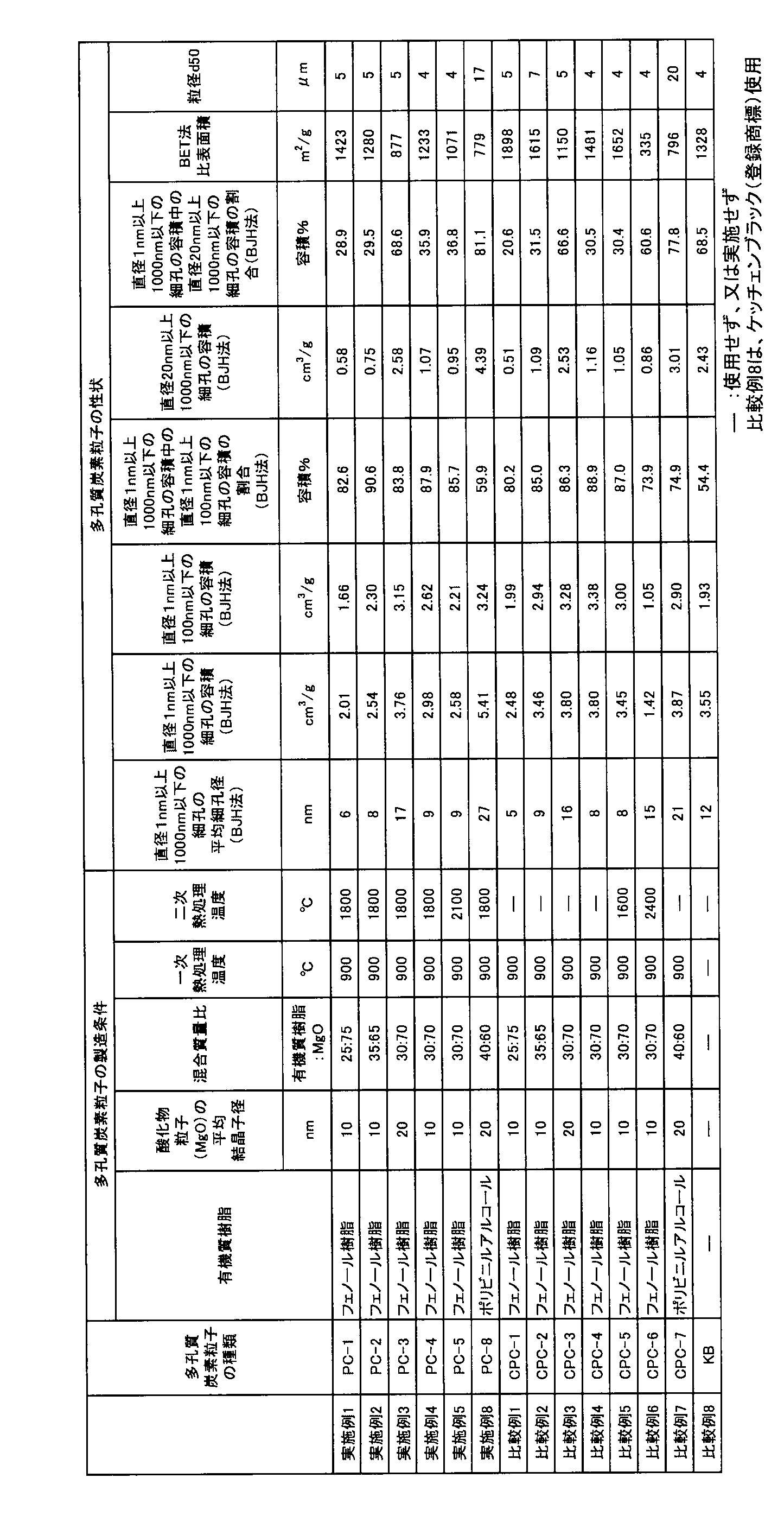
600 コインセル
610 負極構造体
620 正極構造体
630 コインセル型拘束具
635 集電体
640 金属層
650 スペーサー
660 セパレータ
670 空間(電解質充填用空間)
680 金属メッシュ
685 ガスケット
690 多孔炭素膜電極
100 負極構造体
500 積層型空気電池
510 正極構造体
520 負極用集電体
525 正極用集電体
540 セパレータ
550 多孔炭素膜電極
560 ガス拡散層
800 (CR2032型)コインセル
810 正極缶
815 負極缶
820 金属メッシュ
830 ガス拡散層
840 正極(多孔炭素膜)
850 セパレータ
860 負極(金属層)
870 スペーサー
875 皿ばね
880 ガスケット
200 サイクル特性評価用セル
101 正極(多孔炭素膜)
102 ガス拡散層
103 正極集電体
104 負極構造体
105 負極(金属リチウム)
106 負極集電体
107 非水電解質層
108 固体電解質膜
109 セパレータ
110 ガラスプレート
111 ステンレス板
112 固定ネジ
113 固定用座金
114 支柱
115 スプリング
116 スペーサー
118 正極構造体
Claims (6)
- [規則91に基づく訂正 12.11.2024]
下記a)からg)を全て満たす、空気電池の正極に用いる多孔炭素膜形成用の多孔質炭素粒子。
a)ラマンスペクトルにおけるDバンドピークの半値幅が、30cm-1以上60cm-1以下である。
b)ラマンスペクトルにおけるGバンドピークの半値幅が、32cm-1以上80cm-1以下である。
c)ラマンスペクトルにおけるGバンドピークの強度に対するDバンドピークの強度の比であるR値が、0.8以上である。
d)エックス線回折法(XRD)による、炭素の(002)面の間の面間隔d002が0.336nm以上0.355nm以下の部分を有する。
e)窒素吸着法で得られた吸着等温線からBJH法により求めた、直径1nm以上1000nm以下の細孔の容積が、1.5cm3/g以上10.0cm3/g以下である。
f)窒素吸着法で得られた吸着等温線からBJH法により求めた、直径1nm以上100nm以下の細孔の容積が、1.0cm3/g以上8.0cm3/g以下である。
g)窒素吸着法で得られた吸着等温線からBET法により求めた比表面積が、500cm2/g以上2000cm2/g以下である。 - 請求項1に記載の多孔質炭素粒子を含むと共に、下記A)からD)を全て満たす、空気電池の正極用の多孔炭素膜。
A)ラマンスペクトルにおけるDバンドピークの半値幅が64cm-1未満である。
B)窒素吸着法で得られた吸着等温線からBJH法により求めた、直径1nm以上1000nm以下の細孔の容積が、1.2cm3/g以上8.0cm3/g以下である。
C)窒素吸着法で得られた吸着等温線からBJH法により求めた、直径1nm以上100nm以下の細孔の容積が、0.8cm3/g以上7.0cm3/g以下である。
D)窒素吸着法で得られた吸着等温線からBET法により求めた比表面積が、400cm2/g以上2000cm2/g以下である。 - 前記A)ラマンスペクトルにおけるDバンドピークの半値幅が37cm-1以上である、請求項2に記載の多孔炭素膜。
- 見かけ密度が0.10g/cm3以上0.20cm3/g以下である、請求項2又は3に記載の多孔炭素膜。
- 空隙率が85%以上99%以下である、請求項2から4のいずれか1項に記載の多孔炭素膜。
- 請求項2から5のいずれか1項に記載の多孔炭素膜を正極に備える空気電池。
Priority Applications (2)
| Application Number | Priority Date | Filing Date | Title |
|---|---|---|---|
| KR1020267012850A KR20260079321A (ko) | 2023-11-22 | 2024-09-30 | 공기 전지의 정극에 사용하는 다공 탄소막 형성용 다공질 탄소 입자, 공기 전지의 정극용 다공 탄소막 및 공기 전지 |
| CN202480070953.7A CN122295766A (zh) | 2023-11-22 | 2024-09-30 | 空气电池的正极中使用的多孔碳膜形成用的多孔碳粒子、空气电池的正极用的多孔碳膜、以及空气电池 |
Applications Claiming Priority (2)
| Application Number | Priority Date | Filing Date | Title |
|---|---|---|---|
| JP2023198522 | 2023-11-22 | ||
| JP2023-198522 | 2023-11-22 |
Publications (1)
| Publication Number | Publication Date |
|---|---|
| WO2025109869A1 true WO2025109869A1 (ja) | 2025-05-30 |
Family
ID=95826304
Family Applications (1)
| Application Number | Title | Priority Date | Filing Date |
|---|---|---|---|
| PCT/JP2024/034872 Pending WO2025109869A1 (ja) | 2023-11-22 | 2024-09-30 | 空気電池の正極に用いる多孔炭素膜形成用の多孔質炭素粒子、空気電池の正極用の多孔炭素膜、及び空気電池 |
Country Status (3)
| Country | Link |
|---|---|
| KR (1) | KR20260079321A (ja) |
| CN (1) | CN122295766A (ja) |
| WO (1) | WO2025109869A1 (ja) |
Citations (4)
| Publication number | Priority date | Publication date | Assignee | Title |
|---|---|---|---|---|
| JP2015204216A (ja) * | 2014-04-15 | 2015-11-16 | トヨタ自動車株式会社 | 燃料電池用電極触媒、及び燃料電池用電極触媒の製造方法 |
| JP2017073310A (ja) * | 2015-10-08 | 2017-04-13 | 新日鐵住金株式会社 | 燃料電池用触媒層及び燃料電池 |
| JP2020126816A (ja) * | 2019-02-06 | 2020-08-20 | トヨタ自動車株式会社 | 燃料電池用触媒 |
| JP2021034128A (ja) * | 2019-08-15 | 2021-03-01 | トヨタ自動車株式会社 | 燃料電池触媒担体用の黒鉛化炭素多孔体、燃料電池触媒、及び燃料電池触媒層の製造方法 |
Family Cites Families (4)
| Publication number | Priority date | Publication date | Assignee | Title |
|---|---|---|---|---|
| JP3515492B2 (ja) | 2000-06-30 | 2004-04-05 | 株式会社東芝 | 非水電解質電池 |
| JP5860600B2 (ja) | 2011-03-09 | 2016-02-16 | 東洋炭素株式会社 | 多孔質炭素 |
| JP2015076125A (ja) | 2013-10-04 | 2015-04-20 | トヨタ自動車株式会社 | 多孔質炭素及び金属空気電池 |
| JP7177547B2 (ja) | 2019-05-23 | 2022-11-24 | 国立研究開発法人物質・材料研究機構 | 多孔炭素構造体、その製造方法、それを用いた正極材及びそれを用いた電池 |
-
2024
- 2024-09-30 WO PCT/JP2024/034872 patent/WO2025109869A1/ja active Pending
- 2024-09-30 KR KR1020267012850A patent/KR20260079321A/ko active Pending
- 2024-09-30 CN CN202480070953.7A patent/CN122295766A/zh active Pending
Patent Citations (4)
| Publication number | Priority date | Publication date | Assignee | Title |
|---|---|---|---|---|
| JP2015204216A (ja) * | 2014-04-15 | 2015-11-16 | トヨタ自動車株式会社 | 燃料電池用電極触媒、及び燃料電池用電極触媒の製造方法 |
| JP2017073310A (ja) * | 2015-10-08 | 2017-04-13 | 新日鐵住金株式会社 | 燃料電池用触媒層及び燃料電池 |
| JP2020126816A (ja) * | 2019-02-06 | 2020-08-20 | トヨタ自動車株式会社 | 燃料電池用触媒 |
| JP2021034128A (ja) * | 2019-08-15 | 2021-03-01 | トヨタ自動車株式会社 | 燃料電池触媒担体用の黒鉛化炭素多孔体、燃料電池触媒、及び燃料電池触媒層の製造方法 |
Also Published As
| Publication number | Publication date |
|---|---|
| CN122295766A (zh) | 2026-06-26 |
| KR20260079321A (ko) | 2026-06-01 |
Similar Documents
| Publication | Publication Date | Title |
|---|---|---|
| KR102106148B1 (ko) | 비수 이차 전지용 부극 및 비수 이차 전지 | |
| KR102189548B1 (ko) | 리튬 이차 전지용 음극 활물질, 및 이를 포함하는 리튬 이차 전지 | |
| JP6116144B2 (ja) | 負極活物質、それを含む電極、それを採用したリチウム電池及びその製造方法 | |
| US6569570B2 (en) | Carbonaceous electrode material for secondary battery | |
| KR102319096B1 (ko) | 탄소질 피복 흑연 입자의 제조 방법 | |
| JP7328865B2 (ja) | 多孔質炭素材料、多孔質炭素材料の製造方法、複合体、複合体の製造方法、リチウム硫黄電池用の正極、及びリチウム硫黄電池 | |
| JP6858691B2 (ja) | リチウムイオン二次電池負極材料用炭素質被覆黒鉛質粒子の製造方法 | |
| JP7177547B2 (ja) | 多孔炭素構造体、その製造方法、それを用いた正極材及びそれを用いた電池 | |
| CA3012863C (en) | Immobilized selenium, a method of making, and uses of immobilized selenium in a rechargeable battery | |
| KR20100024802A (ko) | 다공성 애노드 활물질, 그 제조방법, 이를 포함한 애노드 및 리튬 전지 | |
| JP5718874B2 (ja) | リチウム空気電池正極用炭素材料及びリチウム空気電池 | |
| US20110117415A1 (en) | Nonaqueous electrolyte secondary battery | |
| JP2002348109A (ja) | リチウム二次電池用負極材料およびその製造方法、ならびにそれを用いた二次電池 | |
| CN112313821A (zh) | 正极活性物质及电池 | |
| JP7620831B2 (ja) | 非水電解質二次電池用負極材料および非水電解質二次電池 | |
| EP2181471A2 (en) | Porous network negative electrodes for non-aqueous electrolyte secondary battery | |
| JP2011243567A (ja) | リチウムイオン二次電池用負極材料およびその製造方法、リチウムイオン二次電池用負極ならびにリチウムイオン二次電池 | |
| JP7541767B2 (ja) | 空気電池用正極シート、それを製造する方法、および、それを用いた空気電池 | |
| JP7486129B2 (ja) | 空気電池正極用の多孔炭素膜の製造方法、及びその方法で得られる多孔炭素膜を正極に用いた空気電池の製造方法 | |
| JP7660398B2 (ja) | リチウム硫黄電池 | |
| JP7497037B2 (ja) | 空気電池の正極用多孔炭素膜電極、及びそれを用いた空気電池 | |
| JP7648126B2 (ja) | 空気電池用正極シート、および、それを用いた空気電池 | |
| JP7525116B2 (ja) | 多孔炭素膜製造用組成物、及び多孔炭素膜製造用シート | |
| JP5021979B2 (ja) | リチウムイオン二次電池負極材料用メソカーボン小球体黒鉛化物およびその製造方法、リチウムイオン二次電池負極材料、リチウムイオン二次電池負極ならびにリチウムイオン二次電池 | |
| CN118451564A (zh) | 负极活性物质及负极 |
Legal Events
| Date | Code | Title | Description |
|---|---|---|---|
| 121 | Ep: the epo has been informed by wipo that ep was designated in this application |
Ref document number: 24893863 Country of ref document: EP Kind code of ref document: A1 |
|
| ENP | Entry into the national phase |
Ref document number: 2025559069 Country of ref document: JP Kind code of ref document: A |
|
| ENP | Entry into the national phase |
Ref document number: 1020267012850 Country of ref document: KR Free format text: ST27 STATUS EVENT CODE: A-0-1-A10-A15-NAP-PA0105 (AS PROVIDED BY THE NATIONAL OFFICE) |
|
| WWE | Wipo information: entry into national phase |
Ref document number: 1020267012850 Country of ref document: KR |
|
| WWP | Wipo information: published in national office |
Ref document number: 1020267012850 Country of ref document: KR |