WO2025109645A1 - 床構造 - Google Patents
床構造 Download PDFInfo
- Publication number
- WO2025109645A1 WO2025109645A1 PCT/JP2023/041598 JP2023041598W WO2025109645A1 WO 2025109645 A1 WO2025109645 A1 WO 2025109645A1 JP 2023041598 W JP2023041598 W JP 2023041598W WO 2025109645 A1 WO2025109645 A1 WO 2025109645A1
- Authority
- WO
- WIPO (PCT)
- Prior art keywords
- floor panel
- floor
- support
- steel beam
- panel support
- Prior art date
- Legal status (The legal status is an assumption and is not a legal conclusion. Google has not performed a legal analysis and makes no representation as to the accuracy of the status listed.)
- Pending
Links
Images





Classifications
-
- E—FIXED CONSTRUCTIONS
- E04—BUILDING
- E04B—GENERAL BUILDING CONSTRUCTIONS; WALLS, e.g. PARTITIONS; ROOFS; FLOORS; CEILINGS; INSULATION OR OTHER PROTECTION OF BUILDINGS
- E04B5/00—Floors; Floor construction with regard to insulation; Connections specially adapted therefor
- E04B5/02—Load-carrying floor structures formed substantially of prefabricated units
Definitions
- the invention disclosed in this application relates to a floor structure in which, when at least some of the floor beams that make up the floor surface of a frame structure are made of steel beams, wooden floor panels are laid and fixed on top of the steel beams.
- a wooden floor panel made of thick structural plywood or the like is laid on top of the floor surface surrounded by a rectangle by intersecting floor beams, and the floor panel is directly fastened to the tops of the floor beams with nails or screws to strengthen the rigidity of the floor surface, a method known as a "rigid floor construction method.”
- a floor structure disclosed in Patent Document 1 is known as a technique for joining floor panels made of wood to steel beams.
- a support member made of angle steel is bolted to the side of the web of a steel beam made of H-shaped steel, the horizontal piece of the support member is extended to the side of the steel beam, a floor panel made of cross-laminated timber (CLT) is placed on top of it, and the horizontal piece of the support member is fastened to the underside of the floor panel with screws.
- CLT cross-laminated timber
- a scaffold is required to screw the support member to the floor panel from below. Since workers are forced to perform a wide range of upward screwing work, there is room for improvement in terms of workability.
- the floor panel is dropped to the side of the steel beam, it is also necessary to layer a floor sub-surface made of plywood or the like on top of the floor panel and the steel beam.
- the invention disclosed in this application was made in consideration of the above-mentioned circumstances, and aims to solve the problem of a floor structure in which, when at least some of the floor beams that make up the floor structure are made of steel beams, floor panels made of structural plywood or other wood materials are laid and fixed on top of the steel beams, while ensuring sufficient floor rigidity and improving workability while streamlining the dimensional fit in the height direction, including the floor panels.
- the basic configuration of the floor structure adopted by the invention disclosed in this application to achieve the above-mentioned objectives is characterized as follows: at least one floor panel support member made of wood is attached to the side of a steel beam that constitutes at least one side of the floor structural surface, the top end of the steel beam and the top end of the floor panel support member are aligned flush with each other, at least one floor panel made of wood is laid on top of the steel beam and the floor panel support member, and the floor panel is fastened to the floor panel support member with nails or screws.
- the floor panel support member is a rectangular cross-section floor panel support beam that has a predetermined material length and is arranged parallel to the steel beam, and at least a pair of beam support hardware is attached to the side of the web of the steel beam with a gap equivalent to the material length of the floor panel support beam, and the floor panel support beam can be attached to the side of the steel beam by joining both ends to the pair of beam support hardware.
- the beam support hardware has a rectangular attachment base that is connected to the steel beam side via an appropriate connection means and is held in a position perpendicular to the material axis of the steel beam, and a pair of beam insertion pieces that are bent at a right angle in a plan view from both side edges of the attachment base and extend parallel to the material axis of the steel beam, and a receiving groove is formed in the upper edge of the beam insertion piece and multiple through holes are formed in the middle part of the beam insertion piece, and the beam insertion piece is inserted into a slit formed in the end of the floor panel support beam, and a pin member that crosses the slit and penetrates the floor panel support beam in the beam width direction engages with the receiving groove or the through hole of the beam insertion piece, so that the floor panel support beam can be joined to the beam support hardware.
- the connecting means for connecting the beam support hardware to the steel beam may be configured to include at least one stiffener joined to the side of the steel beam in a direction perpendicular to the material axis of the steel beam, and at least one beam support hardware support connected to the stiffener and protruding to the side of the steel beam.
- the beam support hardware may have its attachment base fastened to the beam support hardware support by bolts and nuts. Furthermore, at least a pair of the beam support hardware may be connected back-to-back with the beam support hardware support sandwiched between the attachment bases of the two.
- the floor panel support member is a floor panel support block in which a plate piece of the same thickness as the upper flange of the steel beam is overlaid on part of the upper surface of a rectangular parallelepiped, or a notch of the same thickness as the upper flange of the steel beam is formed
- the attachment means for attaching the floor panel support block to the steel beam can be configured to include at least one pair of stiffeners that are joined to the side of the steel beam in a direction perpendicular to the material axis of the steel beam and face each other at a distance equivalent to the length of the floor surface material support block, and multiple pin members that penetrate the floor panel support block in the length direction and engage with multiple mounting holes formed in the stiffener pair.
- the invention disclosed in this application allows the floor panel to be installed in the floor structure having the basic configuration described above in one of the following three configurations:
- the portion laid on the steel beam and the portion laid on the floor panel support are arranged so as to be separated along the boundary between the steel beam and the floor panel support, and the floor panel in the portion laid on the steel beam is attached to the top end of the steel beam via adhesive, double-sided tape, or clips.
- the edge of the portion laid on the steel beam is positioned so as to extend over the floor panel support material across the boundary between the steel beam and the floor panel support material, and is fastened to the floor panel support material with nails or screws.
- the tops of the wooden and steel beams that make up the floor surface are aligned flush, and floor panels made of wooden material are laid on top of them.
- the height dimension is fitted in a simple and rational way without increasing the depth of the floor beams or stacking extra materials above or below them, ensuring the levelness of the ground beneath the floor, so the ceiling height and window opening height of the lower floors are not unnecessarily restricted.
- the floor panels can be fastened from above with nails or screws to floor panel support members made of wood attached to the sides of the steel beams. All of the members used to attach the floor panel support members to the sides of the steel beams, except for the stiffeners welded to the webs of the steel beams, can be bolt-and-nut or pin-jointed, greatly improving workability at the construction site.
- the vertical and horizontal loads acting on the floor structure are transferred from the floor panels to the steel beams via the floor panel support beams, providing favorable floor rigidity.
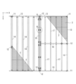
- FIG. 1 is a plan view showing an example of a mixed wood-steel floor structure to which the invention disclosed in this application is applied.
- FIG. 2 is a partial plan view of a column-beam joint (part A) in the floor structure of FIG. 1.
- FIG. 13 is a partial side view of the column-beam joint (part A) of the same embodiment.
- FIG. 13 is an exploded perspective view of the column-beam joint (part A) of the same embodiment.
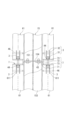
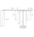
- FIG. 2 is a partial plan view of the joint (part B) between the steel beam and the floor panel support beam in the floor structure of FIG. 1.
- FIG. 2 is a partial side view of the joint (part B) between the steel beam and the floor panel support beam.
- FIG. 1 is a plan view showing an example of a mixed wood-steel floor structure to which the invention disclosed in this application is applied.
- FIG. 2 is a partial plan view of a column-beam joint (part A) in the floor structure of FIG. 1.
- FIG. 13
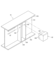
- FIG. 13 is an exploded perspective view of the joint (part B) between the steel beam and the floor panel support beam.
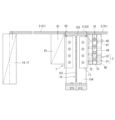
- FIG. 11 is a partial side view showing a joining form between a steel beam and a floor panel support block as another embodiment applied to part B.
- FIG. 4 is an exploded perspective view showing the connection between a steel beam and a floor panel support block.
- FIG. 11 is a partial side view showing another example of the installation form of the floor panel relative to the steel beam and the floor panel support.
- 13 is a partial side view showing yet another example of the installation form of the floor panel relative to the steel beam and the floor panel support material.
- Figure 1 shows an example of a mixed wood and steel floor structure to which the invention disclosed in this application is applied.
- This floor structure 1 is constructed by framing wooden beams with a vertically long rectangular cross section made of solid wood, laminated wood, or other wooden materials so that their top ends form the same plane.
- the illustrated floor structure 1 has a size of two spans in each of the X and Y directions, with one span (the standard distance between the column centers) being approximately 4.5 meters.
- wooden beams 13 having a material length of one span are erected between four corner columns 11 made of wooden materials and a column 12 in the middle.
- one steel beam 15 made of H-shaped steel and having a length of two spans is erected in the Y direction.
- a wooden beam 16 with a length of one span is installed in the X direction, and between the wooden beam 16 and the outer periphery of the wooden beam 13, multiple wooden beams 17 are installed in the Y direction. This creates a space with no columns in the center, which is two spans in length and width.
- Floor panels 2 made of structural plywood or other wood materials are laid on top of this floor structural surface 1.
- the floor panels 2 are formed so that at least one side length is greater than or equal to the distance between adjacent wooden beams 13, 17 or beams 14, and are spanned between adjacent wooden beams 13, 17 or beams 14, with at least the edges of the two opposing sides fastened to the wooden beams 13, 16, 17, beams 14, etc. with multiple nails or screws.
- Fig. 2 to Fig. 4 show the joint structure of the column-beam joint (circled part A) on the outer periphery of the floor structural surface 1 in Fig. 1.
- two wooden beams 13, 13 are joined so that they are continuous in the X direction, sandwiching a single column 12 made of wooden material with a square cross section between them, and further, a single steel beam 15 is joined in the Y direction perpendicular to the wooden beams 13, 13.
- the column 12 and wooden beam are joined using a beam support hardware 3 as shown in Figure 4 so that the column wins.
- the illustrated beam support hardware 3 is a hardware made by bending a steel plate into a roughly U-shape in plan view, which has been conventionally used in buildings with wooden frame structures.
- the beam support hardware 3 has a long rectangular attachment base 31 that is attached to the side of the column 12, and a pair of parallel beam insertion pieces 32, 32 that bend at a right angle in plan view from both side edges of the attachment base 31 and extend away from the column 12.
- the attachment base 31 has multiple mounting holes (not shown) formed in a vertical line at a predetermined interval, and the beam support hardware 3 is attached to the side of the column 12 by inserting bolts 41 through the mounting holes, passing them through the column 12, and tightening them with nuts.
- two beam support brackets 3, 3 are attached to the two opposing sides of the column 12 so that they are back-to-back with the column 12 in between, and are fastened together by bolts and nuts that pass through the column 12.
- Each beam insertion piece 32 of the beam support hardware 3 also has multiple through holes 33 formed vertically at a predetermined interval, and a receiving groove 34 is formed on the upper edge.
- the wooden beam 13 has two parallel slits 131, 131 opening into its end face, and multiple pin member insertion holes 132 intersecting the slits 131, 131 and penetrating the wooden beam 13 in the beam width direction, formed vertically at a predetermined interval.
- the spacing between the slits 131, 131 matches the spacing between the beam insertion pieces 32, 32 of the beam support hardware 3, and the end face of the portion sandwiched between the slits 131, 131 is cut so as not to interfere with the head of the bolt 41 that attaches the beam support hardware 3 to the column 12.
- this beam support hardware 3 is also used in column-beam joints other than part A and in orthogonal joints between wooden beams.
- the steel beam 15 is joined to the side of the joint between the column 12 and the two wooden beams 13, 13 formed in this way via the steel beam connector 5 and a pair of splice plates 54.
- the steel beam connector 5 is a steel member that is T-shaped in plan view and has a rectangular mounting base 51 and a web joint piece 52 that protrudes from the center of the mounting base 51 perpendicular to the mounting base 51.
- Mounting holes 53 are formed near both side edges of the mounting base 51, aligned vertically at a predetermined interval so as to match the positions of the pin members (bolts 42) that join the beam support hardware 3 and the wooden beam 13.
- the bolts 42 that join the beam support hardware 3 and the wooden beam 13 are inserted into these mounting holes 53 and fastened together, so that the steel beam connector 5 is attached to the side of the joint between the column 12 and the two wooden beams 13, 13.
- the web joint piece 52 of the steel beam connector 5 and the web 151 of the steel beam 15 each have a plurality of connection holes 521, 156 formed vertically at a predetermined interval.
- the end faces of the web joint piece 52 and the web 151 are butted together, and their both sides are sandwiched between a pair of splice plates 54, 54 with connection holes 541 formed at the same position and bolted and nut fastened.
- a column-beam joint that is T-shaped in plan view is formed, with the steel beam 15 joined to the side of the joint between the column 12 and the two wooden beams 13.
- an auxiliary support 18 made of a square steel pipe or the like is erected below the end of the steel beam 15 to support the lower flange 152 of the steel beam 15. This makes it possible to reduce the required strength (size of steel plate, plate thickness, number of bolts and nuts, etc.) of the steel beam connector 5 and the splice plate 54.
- Figures 5 to 7 show the structure of the middle part (circled part B) of the steel beam 15 in the floor structural surface 1 in Figure 1. Since the floor panel 2 cannot be directly fastened to the steel beam 15 with nails or screws in this area, a floor panel support member made of wood is attached to the side of the steel beam 15, and the floor panel 2 is fastened to the floor panel support member.
- This floor structure is the essential part of the invention disclosed in this application.
- the floor panel support member in the illustrated embodiment is a floor panel support beam 61 with a vertically elongated rectangular cross section made of solid wood, laminated wood, or other wood material.
- the beam width of the floor panel support beam 61 is equal to that of the wooden beam 13 described above, the beam depth is smaller than that of the wooden beam 13 described above, and the material length is set to about 1/2 the span.
- This floor panel support beam 61 is attached to a stiffener (rib plate) 154 welded to the side of the steel beam 15 by combining the same beam support hardware 3 as described above with a separately prepared beam support hardware support 7.
- the stiffener 154 is welded to the web 151, lower flange 152, and upper flange 153 of the steel beam 15 in a direction perpendicular to the material axis of the steel beam 15.
- the stiffener 154 has multiple mounting holes 155 formed in it, aligned vertically at a predetermined interval.
- the beam support hardware support 7 shown in the center of Figures 5, 6, and 7 comprises a support piece 71 joined to the stiffener 154 and extending out to the side of the steel beam 15, a widening piece 72 joined to the edge of the support piece 71 so as to be perpendicular to the support piece 71, and a pair of parallel beam support pieces 73, 73 extending out to the side of the steel beam 15 from both side edges of the widening piece 72.
- the support piece 71 has a number of bolt insertion holes 74 formed therein that match the mounting holes 155 formed in the stiffener 154.
- the support piece 71 is placed on the stiffener 154, and bolts 43 are inserted into the bolt insertion holes 74 and mounting holes 155 and fastened with nuts, thereby joining the support piece 71 to the stiffener 154.
- the beam support piece 73 also has a number of bolt insertion holes formed therein that match the mounting holes 311 formed in the attachment base 31 of the beam support hardware 3.
- the attachment base 31 of the beam support hardware 3 is placed on the beam support piece 73, and bolts 44 are inserted into the bolt insertion holes and mounting holes 311 and fastened with nuts.
- the two beam support hardware 3, 3 are placed back-to-back with the beam support hardware support 7 sandwiched between the attachment bases 31, and the respective beam insertion pieces 32, 32 are connected so that they are facing each other back-to-back and parallel to the material axis of the steel beam 15.
- the floor panel support beam 61 has two parallel slits 611, 611 opening into its end face, and multiple pin member insertion holes 612 that intersect the slits 611, 611 and penetrate the floor panel support beam 61 in the beam width direction, lined up vertically at a specified interval.
- the interval between the two slits 611, 611 matches the opposing interval between the two beam insertion pieces 32, 32 of the beam support hardware 3, and the end face of the portion sandwiched between the two slits 611, 611 is cut so as not to interfere with the head of the bolt 44 that attaches the beam support hardware 3 to the beam support hardware support 7.
- the beam insertion pieces 32, 32 of the beam support hardware 3 are inserted into the slits 611, 611 of the floor panel support beam 61, and the pin member (bolt 45 or drift pin 46) inserted into the pin member insertion hole 612 of the floor panel support beam 61 engages with the through hole 33 or receiving groove 34 of the beam insertion pieces 32, 32, so that the floor panel support beam 61 is joined to the beam support hardware 3 and the beam support hardware support 7 and held parallel to the steel beam 15.
- the beam support hardware support 7 can also be configured as a single plate formed by integrating a support piece 71 joined to the stiffener 154 with a single beam support piece 73, with a pair of beam support hardware 3 attached back-to-back to both sides of the plate.
- each part of the beam support hardware support 7 and the positions of the bolt insertion holes 74, etc. are set so that the top end of the floor panel support beam 61 attached to the steel beam 15 is flush with the top end of the steel beam 15.
- a floor panel 2 made of structural plywood or other wood material is laid on the floor panel support beam 61 and fastened to the floor panel support beam 61 with a plurality of nails 81 or screws. This fastening work can be performed from above the floor panel 2.
- the horizontality of the floor surface can be ensured by a simple and rational fit without increasing the beam depth of the floor beam or stacking extra members above or below the floor beam. Therefore, the ceiling height and window opening height of the lower floors are not unnecessarily restricted.
- the floor panel 2 (21) laid on the floor panel support beam 61 and the floor panel 2 (22) laid on the steel beam 15 are separated along the boundary between the steel beam 15 and the floor panel support beam 61.
- a floor panel 22 with a plate width that roughly matches the flange width of the steel beam 15 is laid on top of the steel beam 15, but since the floor panel 22 has a smaller area than the floor panel 21 laid over the entire floor structure 1, it can be attached to the top end of the steel beam 15 using adhesive or double-sided tape. Alternatively, it can be attached using a clip 82 that is roughly C-shaped in side view and clamps the edges of the steel beam 15 and floor panel 22 together, as shown in FIG. 6.
- FIGS 8 and 9 show another embodiment of the floor panel support member and its mounting structure.
- the floor panel support member shown is a floor panel support block 62 made of solid wood, laminated wood, or other wood material formed into a short rectangular parallelepiped shape.
- a step 621 is formed on the top surface of the floor panel support block 62 by overlapping pieces of board or by forming a recess, corresponding to the thickness of the upper flange 153 of the steel beam 15.
- This floor panel support block 62 is attached to two stiffeners (stiffener pair) 154, 154 that are joined to the sides of the steel beam 15 in a direction perpendicular to the material axis of the steel beam 15.
- the two stiffeners 154, 154 are attached with a gap equivalent to the length of the floor panel support block 62 (the dimension in the direction parallel to the material axis of the steel beam 15), and multiple mounting holes 155 are formed at the same positions in the middle.
- the floor panel support block 62 also has multiple pin member insertion holes 622 formed in it that match the mounting holes 155 formed in the stiffener 154, and by overlapping these and inserting pin members (bolts or drift pins 47) through them, the floor panel support block 62 is attached to the side of the steel beam 15 with roughly half of it submerged below the upper flange 153 of the steel beam 15. Even in this form, the positions of the mounting holes 155, etc. are set so that the top end of the steel beam 15 and the top end of the floor panel support block 62 are aligned flush, and the floor panel 2 laid on the floor panel support block 62 is fastened to the floor panel block 62 with multiple nails 81 or screws.
- the floor structure described above makes it possible to fasten the floor panel 2 to the floor surface 1 using only nails 81 or screws, even when a steel beam 15 is placed on part of the floor surface 1.
- All means for attaching the floor panel support beam 61 and floor panel support block 62 to the side of the steel beam 15, except for the stiffener 154 welded to the web 151 of the steel beam 15, can be bolt-nut or pin joints, greatly improving workability at the construction site.
- the vertical and horizontal loads acting on the floor surface 1 are transmitted from the floor panel 2 to the steel beam 15 via the floor panel support member, so favorable floor surface rigidity can be obtained.
- Figures 10 and 11 show other configurations for laying and fastening the floor panel 2.
- the edge of the floor panel 21 laid on the floor panel support member (floor panel support beam 61) is positioned so that it extends across the boundary between the steel beam 15 and the floor panel support beam 61 to near the center of the steel beam 15's axis.
- the floor panel 21 is fastened to the floor panel support beam 61 with multiple nails 81 or screws. In other words, in this configuration, only the vicinity of the edge of the floor panel 21 rests on the steel beam 15.
- the floor panel 22 laid on the steel beams 15 is formed to be larger than the width of the steel beams 15, and is positioned so that its edge extends over the boundary between the steel beams 15 and the floor panel support beams 61 and onto the floor panel support beams 61.
- the floor panel 22 is fastened to the floor panel support beams 61 with multiple nails 81 or screws. Therefore, even in this form, the floor panel 22 is simply placed on the steel beams 15.
- the floor structure described above ensures floor rigidity by stacking the floor panels 2 directly on the tops of the steel beams 15 and wooden beams. In other words, there is no need to increase the depth of the floor beams or stack extra components above or below them, which avoids unnecessarily restricting the ceiling height and window opening height of the lower floors.
- the dimensional fit in the height direction, including the floor panels 2 is streamlined, sufficient floor rigidity is ensured, and workability is improved.
- the invention disclosed in this application can be particularly well suited for use as a floor structure when using rigid floor construction in buildings with a mixed wood and steel frame structure.
Landscapes
- Engineering & Computer Science (AREA)
- Architecture (AREA)
- Physics & Mathematics (AREA)
- Electromagnetism (AREA)
- Civil Engineering (AREA)
- Structural Engineering (AREA)
- Joining Of Building Structures In Genera (AREA)
- Floor Finish (AREA)
Priority Applications (3)
| Application Number | Priority Date | Filing Date | Title |
|---|---|---|---|
| PCT/JP2023/041598 WO2025109645A1 (ja) | 2023-11-20 | 2023-11-20 | 床構造 |
| JP2025558924A JPWO2025109645A1 (https=) | 2023-11-20 | 2023-11-20 | |
| AU2023473814A AU2023473814A1 (en) | 2023-11-20 | 2023-11-20 | Floor structure |
Applications Claiming Priority (1)
| Application Number | Priority Date | Filing Date | Title |
|---|---|---|---|
| PCT/JP2023/041598 WO2025109645A1 (ja) | 2023-11-20 | 2023-11-20 | 床構造 |
Publications (1)
| Publication Number | Publication Date |
|---|---|
| WO2025109645A1 true WO2025109645A1 (ja) | 2025-05-30 |
Family
ID=95826344
Family Applications (1)
| Application Number | Title | Priority Date | Filing Date |
|---|---|---|---|
| PCT/JP2023/041598 Pending WO2025109645A1 (ja) | 2023-11-20 | 2023-11-20 | 床構造 |
Country Status (3)
| Country | Link |
|---|---|
| JP (1) | JPWO2025109645A1 (https=) |
| AU (1) | AU2023473814A1 (https=) |
| WO (1) | WO2025109645A1 (https=) |
Citations (10)
| Publication number | Priority date | Publication date | Assignee | Title |
|---|---|---|---|---|
| JPS5055720U (https=) * | 1973-09-14 | 1975-05-27 | ||
| JPS50122027A (https=) * | 1974-03-12 | 1975-09-25 | ||
| JPS5747601U (https=) * | 1980-08-31 | 1982-03-17 | ||
| JPS5780506U (https=) * | 1980-11-03 | 1982-05-18 | ||
| JPS58191844A (ja) * | 1982-04-30 | 1983-11-09 | ミサワホ−ム株式会社 | 床パネル |
| JPS5932019U (ja) * | 1982-08-25 | 1984-02-28 | ナシヨナル住宅産業株式会社 | 床パネル取付構造 |
| JPS59102036A (ja) * | 1982-12-01 | 1984-06-12 | 旭化成株式会社 | 建築構造 |
| JPS5988126U (ja) * | 1982-12-07 | 1984-06-14 | 植原鉄構有限会社 | 木造用フリ−サイズ軽量h型鋼梁 |
| JP2006328646A (ja) * | 2005-05-23 | 2006-12-07 | Sekisui House Ltd | 大梁と小梁の接合部構造 |
| GB2436335A (en) * | 2006-03-23 | 2007-09-26 | Gang Nail Systems Ltd | Composite joist |
-
2023
- 2023-11-20 AU AU2023473814A patent/AU2023473814A1/en active Pending
- 2023-11-20 JP JP2025558924A patent/JPWO2025109645A1/ja active Pending
- 2023-11-20 WO PCT/JP2023/041598 patent/WO2025109645A1/ja active Pending
Patent Citations (10)
| Publication number | Priority date | Publication date | Assignee | Title |
|---|---|---|---|---|
| JPS5055720U (https=) * | 1973-09-14 | 1975-05-27 | ||
| JPS50122027A (https=) * | 1974-03-12 | 1975-09-25 | ||
| JPS5747601U (https=) * | 1980-08-31 | 1982-03-17 | ||
| JPS5780506U (https=) * | 1980-11-03 | 1982-05-18 | ||
| JPS58191844A (ja) * | 1982-04-30 | 1983-11-09 | ミサワホ−ム株式会社 | 床パネル |
| JPS5932019U (ja) * | 1982-08-25 | 1984-02-28 | ナシヨナル住宅産業株式会社 | 床パネル取付構造 |
| JPS59102036A (ja) * | 1982-12-01 | 1984-06-12 | 旭化成株式会社 | 建築構造 |
| JPS5988126U (ja) * | 1982-12-07 | 1984-06-14 | 植原鉄構有限会社 | 木造用フリ−サイズ軽量h型鋼梁 |
| JP2006328646A (ja) * | 2005-05-23 | 2006-12-07 | Sekisui House Ltd | 大梁と小梁の接合部構造 |
| GB2436335A (en) * | 2006-03-23 | 2007-09-26 | Gang Nail Systems Ltd | Composite joist |
Also Published As
| Publication number | Publication date |
|---|---|
| AU2023473814A1 (en) | 2025-09-25 |
| JPWO2025109645A1 (https=) | 2025-05-30 |
Similar Documents
| Publication | Publication Date | Title |
|---|---|---|
| JP3581426B2 (ja) | 木造建築物の構造材と床構造及び屋根構造並びにそれらを用いた構築工法 | |
| JP2020084729A (ja) | 建築工法および建築構造 | |
| JP6841439B2 (ja) | 建築工法および建築構造 | |
| JP2020143502A (ja) | 耐力壁 | |
| JP2024024423A (ja) | 耐力壁パネル接続構造 | |
| JP3714902B2 (ja) | 柱と横材の接合装置 | |
| JP6595146B1 (ja) | 建築物およびその建築工法 | |
| WO2025109645A1 (ja) | 床構造 | |
| JP6892991B2 (ja) | 壁部材と基礎の接合構造 | |
| JP7032051B2 (ja) | 床構造施工方法および床構造再利用方法 | |
| JP3787140B2 (ja) | 壁体の構造 | |
| JP2015045190A (ja) | 壁補強構造 | |
| JP6564606B2 (ja) | 木・鋼重ね梁構造 | |
| JP7450204B2 (ja) | 支持構造 | |
| JP6886722B2 (ja) | 固定具 | |
| JP7701688B2 (ja) | 木質材料からなる壁部材の設置構造 | |
| JP7677823B2 (ja) | 構造部材の接合構造 | |
| JP7364267B2 (ja) | 木造建物の構造 | |
| JP2019011655A (ja) | 建物ユニットおよび建物 | |
| JPH05148907A (ja) | 住戸ユニツトからなる建築物 | |
| JP7356695B2 (ja) | 木造建物の構造 | |
| JP2025180602A (ja) | 耐震壁構造 | |
| JP7790667B2 (ja) | 耐力壁と耐力壁架構 | |
| JP5385098B2 (ja) | 建築構造用部材 | |
| JP2025012079A (ja) | 木材被覆鉄骨構造およびその構築方法 |
Legal Events
| Date | Code | Title | Description |
|---|---|---|---|
| 121 | Ep: the epo has been informed by wipo that ep was designated in this application |
Ref document number: 23959390 Country of ref document: EP Kind code of ref document: A1 |
|
| ENP | Entry into the national phase |
Ref document number: 2025558924 Country of ref document: JP Kind code of ref document: A |
|
| WWE | Wipo information: entry into national phase |
Ref document number: 2025558924 Country of ref document: JP |
|
| WWE | Wipo information: entry into national phase |
Ref document number: AU2023473814 Country of ref document: AU |
|
| ENP | Entry into the national phase |
Ref document number: 2023473814 Country of ref document: AU Date of ref document: 20231120 Kind code of ref document: A |