WO2025104903A1 - ボールねじ - Google Patents
ボールねじ Download PDFInfo
- Publication number
- WO2025104903A1 WO2025104903A1 PCT/JP2023/041416 JP2023041416W WO2025104903A1 WO 2025104903 A1 WO2025104903 A1 WO 2025104903A1 JP 2023041416 W JP2023041416 W JP 2023041416W WO 2025104903 A1 WO2025104903 A1 WO 2025104903A1
- Authority
- WO
- WIPO (PCT)
- Prior art keywords
- screw
- ball
- groove
- circulation path
- nut
- Prior art date
- Legal status (The legal status is an assumption and is not a legal conclusion. Google has not performed a legal analysis and makes no representation as to the accuracy of the status listed.)
- Pending
Links
Images






Classifications
-
- F—MECHANICAL ENGINEERING; LIGHTING; HEATING; WEAPONS; BLASTING
- F16—ENGINEERING ELEMENTS AND UNITS; GENERAL MEASURES FOR PRODUCING AND MAINTAINING EFFECTIVE FUNCTIONING OF MACHINES OR INSTALLATIONS; THERMAL INSULATION IN GENERAL
- F16H—GEARING
- F16H25/00—Gearings comprising primarily only cams, cam-followers and screw-and-nut mechanisms
- F16H25/18—Gearings comprising primarily only cams, cam-followers and screw-and-nut mechanisms for conveying or interconverting oscillating or reciprocating motions
- F16H25/20—Screw mechanisms
- F16H25/22—Screw mechanisms with balls, rollers, or similar members between the co-operating parts; Elements essential to the use of such members
-
- F—MECHANICAL ENGINEERING; LIGHTING; HEATING; WEAPONS; BLASTING
- F16—ENGINEERING ELEMENTS AND UNITS; GENERAL MEASURES FOR PRODUCING AND MAINTAINING EFFECTIVE FUNCTIONING OF MACHINES OR INSTALLATIONS; THERMAL INSULATION IN GENERAL
- F16H—GEARING
- F16H25/00—Gearings comprising primarily only cams, cam-followers and screw-and-nut mechanisms
- F16H25/18—Gearings comprising primarily only cams, cam-followers and screw-and-nut mechanisms for conveying or interconverting oscillating or reciprocating motions
- F16H25/20—Screw mechanisms
- F16H25/24—Elements essential to such mechanisms, e.g. screws, nuts
Definitions
- This disclosure relates to ball screws.
- a ball screw that includes a screw shaft, a nut, a number of balls, and a bearing member that circulates the balls (see, for example, Patent Document 1, Patent Document 2, Patent Document 3, and Patent Document 4).
- Ball screws are required to ensure smooth ball rolling and circulation over a long period of time. Ball screws also need to be made easier to work with during maintenance and assembly.
- one of the objectives is to provide a ball screw that can improve workability while ensuring smooth ball rolling and circulation over a long period of time.
- the ball screw according to the present disclosure comprises a threaded shaft having a first helical thread groove on its outer circumferential surface, a nut attached to the outer circumferential side of the threaded shaft, having a second helical thread groove on its inner circumferential surface, movable in the longitudinal direction of the threaded shaft, and having an elongated hole penetrating in the radial direction, a plurality of balls that roll in a rolling path formed between the first thread groove and the second thread groove, and a top member attached to the nut so as to cover the elongated hole and provided with a circulation path that guides the balls so that they pass over the threads of the first threaded shaft and enter the adjacent rolling path.
- the top member includes a first member provided with a first groove that constitutes a part of the circulation path, a second member provided with a second groove that constitutes a part of the circulation path and combined with the first member to form the circulation path, a greasing member having a contact portion exposed to the circulation path side and in contact with the balls, and a third member that holds the greasing member so as to cover the outer diameter side of the greasing member.
- the above-mentioned ball screw can improve workability while ensuring smooth ball rolling and circulation over a long period of time.
- FIG. 1 is a schematic perspective view of a ball screw according to a first embodiment of the present disclosure.
- FIG. 2 is a schematic side view of the ball screw shown in FIG.
- FIG. 3 is a schematic cross-sectional view of a portion taken along the line III-III in FIG.
- FIG. 4 is a schematic perspective view showing a nut included in the ball screw.
- FIG. 5 is a schematic perspective view showing the appearance of the piece member.
- FIG. 6 is an exploded perspective view of the link member.
- FIG. 7 is a schematic cross-sectional view of a portion of the piece member.
- FIG. 8 is a schematic perspective view of the link member as viewed from the inner diameter side of the nut.
- FIG. 9 is a schematic perspective view showing a state in which the first member and the second member are combined.
- FIG. 10 is a schematic perspective view showing a state in which the first member and the second member are combined.
- FIG. 11 is a schematic perspective view showing the first member.
- FIG. 12 is a schematic perspective view showing the second member.
- FIG. 13 is a schematic perspective view showing the third member.
- the ball screw of the present disclosure includes a threaded shaft having a first helical thread groove on its outer circumferential surface, a nut attached to the outer circumferential side of the threaded shaft, having a second helical thread groove on its inner circumferential surface, being movable in the longitudinal direction of the threaded shaft and having an elongated hole penetrating in the radial direction, a plurality of balls rolling in a rolling path formed between the first thread groove and the second thread groove, and a top member attached to the nut so as to cover the elongated hole and provided with a circulation path for guiding the balls so that the balls pass over the threads of the first threaded shaft and enter the adjacent rolling path.
- the top member includes a first member provided with a first groove constituting a part of the circulation path, a second member provided with a second groove constituting a part of the circulation path and combined with the first member to form the circulation path, a greasing member having a contact portion exposed to the circulation path side and contacting the balls, and a third member that holds the greasing member so as to cover the outer diameter side of the greasing member.
- the top member is not composed of one part, but is composed of a combination of a first member, a second member, a third member, and a greasing member.
- the circulation path is formed by combining the first groove and the second groove.
- the greasing member has a contact portion exposed to the circulation path and in contact with the ball, the contact portion can graze the ball passing through the circulation path. In this way, it is possible to ensure smooth rolling and circulation of the balls for a long period of time.
- the third member is arranged to cover the outer diameter side of the greasing member, the greasing member is not exposed to the outer diameter side, and as a result, it is possible to prevent the greasing member from drying out. Since the greasing member is held by the third member, when replacing the greasing member, the third member can be removed from the nut. This allows the lubrication member to be replaced without removing the first and second members from the nut, reducing the risk of an increase in assembly man-hours and improving workability. As a result, the ball screw can improve workability while ensuring smooth ball rolling and circulation over a long period of time.
- the greasing member may be plate-shaped. In this way, the thickness direction of the greasing member is arranged in the radial direction of the ball screw, and it is possible to impregnate the greasing member with a relatively large amount of lubricating oil while suppressing an increase in volume, particularly in the radial direction. In addition, the greasing member can be made easier to handle.
- the greasing member may be held so as to be sandwiched between the third member and the second member. In this way, the position of the greasing member can be stably maintained within the top member. Therefore, the balls can be greased more stably for a long period of time.
- the contact portion may have a protruding region that protrudes toward the circulation path.
- the second member may be provided with a housing groove that houses the protruding region. In this way, the lubricating oil can be gradually exuded from the protruding region to grease the balls.
- the protruding region since the protruding region is housed in the housing groove, it is possible to stably hold the protruding region and prevent the greasing position from shifting. Therefore, the balls can be more reliably greased over a long period of time.
- the protruding length of the protruding region may be 30% or more and 70% or less of the diameter of the ball. This allows the ball and the protruding region to be in contact with each other reliably. Therefore, the ball can be more reliably greased. More preferably, the protruding length of the protruding region is selected to be 40% or more and 60% or less of the diameter of the ball.
- the third member may be provided with a storage recess for storing the greasing member.
- the greasing member can be fitted into the storage recess provided in the third member and stored therein, and the greasing member can be held more stably.
- the third member can be attached by fitting the greasing member into the storage recess, improving workability.
- the first member and the third member may each be attached to the nut by a screw.
- the second member may be sandwiched between the first member and the third member.
- the first member and the third member can be securely fixed to the nut by the screw, and the first member and the third member can be removed by turning the screw.
- the second member since the second member is sandwiched between the first member and the third member, it can be more securely fixed to the nut. In other words, by adopting such a configuration, it is possible to easily attach and detach the top member. This makes it easy to replace the greasing member, etc. This can further improve workability.
- multiple top members may be provided at intervals in the circumferential direction. In this way, multiple balls can be circulated smoothly by multiple top members. Therefore, the balls can be circulated more smoothly.
- FIG. 1 is a schematic perspective view of a ball screw in the first embodiment of the present disclosure.
- FIG. 2 is a schematic side view of the ball screw shown in FIG. 1.
- FIG. 2 is a view seen in the opposite direction to the direction of the arrow Y shown in FIG. 1.
- FIG. 3 is a schematic cross-sectional view of a part cut at the cross section shown by III-III in FIG. 1.
- the direction shown by the arrow Z is the longitudinal direction of the screw shaft described later, and the directions shown by the arrows X and Y are radial directions.
- the direction shown by the arrows X and Y are perpendicular to each other.
- the ball screw 10a in the first embodiment includes a screw shaft 11a, a nut 12a, balls 13a as rolling elements, and a plurality of top members 14a, three in this embodiment.
- the balls 13a are, for example, steel balls.
- the screw shaft 11a has a shape that extends in the longitudinal direction (Z direction).
- a first helical screw groove 16a is provided on the outer circumferential surface of the screw shaft 11a over the entire longitudinal area. When the ball screw 10a is viewed from the side, a first screw thread 17a is disposed between adjacent first screw grooves 16a.
- FIG. 4 is a schematic perspective view showing the nut 12a included in the ball screw 10a.
- the nut 12a is attached to the outer periphery of the screw shaft 11a.
- the nut 12a includes a hollow cylindrical tubular portion 21a and a flange portion 22a arranged on one side in the longitudinal direction of the tubular portion 21a.
- the flange portion 22a is rectangular when viewed from the thickness direction, which is the longitudinal direction of the screw shaft 11a, specifically, a square shape with four chamfered corners.
- the nut 12a has a shape in which the tubular portion 21a and the flange portion 22a are connected in the longitudinal direction.
- Nut 12a specifically cylindrical portion 21a included in nut 12a, has multiple, in this embodiment, three long holes 23a, 23b, 23c that penetrate radially.
- Cylindrical portion 21a has three recesses 24a, the outer circumferential surface of which is recessed toward the inner diameter, spaced circumferentially, specifically at intervals of 120 degrees.
- Long holes 23a, 23b, 23c are provided in the areas where these three recesses 24a are located.
- Long holes 23a are each provided at intervals in the circumferential direction.
- long holes 23a, 23b, 23c are provided at intervals in the circumferential direction.
- Long holes 23a, 23b, 23c are also provided at intervals in the axial direction (longitudinal direction (Z direction)).
- Long holes 23a, 23b, 23c are each provided at an inclination in the axial direction. Each of the long holes 23a, 23b, and 23c opens so as to straddle two adjacent first screw grooves 16a when viewed from the outer diameter side when the nut 12a is attached to the outer periphery of the screw shaft 11a. The two first screw grooves 16a straddled by the long holes 23a, 23b, and 23c are offset by one.
- a top member 14a that circulates the ball 13a is attached to each of the long holes 23a, 23b, and 23c. This will be described in detail later.
- multiple screw holes for attaching the top member 14a are provided around the long holes 23a, 23b, and 23c.
- four through holes for attaching other members to the nut 12a are provided near the four corners of the flange portion 22a.
- a second helical screw groove 18a is provided on the inner peripheral surface of the nut 12a.
- a plurality of balls 13a are arranged in a rolling path 19a formed between the first screw groove 16a and the second screw groove 18a.
- the balls 13a roll in the rolling path 19a.
- the nut 12a can move in the longitudinal direction of the screw shaft 11a as the balls 13a circulate while rolling.
- the nut 12a can perform linear reciprocating motion relative to the screw shaft 11a.
- the nut 12a includes a first annular seal ring 25a attached to one longitudinal side where the cylindrical portion 21a is disposed, and a second annular seal ring 26a attached to the other longitudinal side where the flange portion 22a is disposed.
- the first seal ring 25a is fitted into a first fitting recess 27a provided on the inner circumferential side of the cylindrical portion 21a
- the second seal ring 26a is fitted into a second fitting recess 28a provided on the inner circumferential side of the flange portion 22a.
- the inner circumferential surfaces of the first seal ring 25a and the second seal ring 26a are each formed with a thread groove that engages with the first thread groove 16a of the screw shaft 11a.
- the piece member 14a is attached to the nut 12a so as to cover each of the three long holes 23a, 23b, and 23c provided in the nut 12a.
- the piece member 14a is provided with a circulation path 29a that guides the balls 13a in a given first screw groove 16a so that the balls 13a climb over the threads of the screw shaft 11a and enter the adjacent first screw groove 16a.
- the ball screw 10a is provided with a scoop 15a that sequentially supplies the balls 13a from the rolling path 19a to the circulation path 29a.
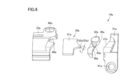
- the link member 14a includes a first member 31a, a second member 32a, a third member 33a, and a greasing member 34a.
- the first member 31a, the second member 32a, and the third member 33a are made of rigid members, for example, metal.
- the material of the first member 31a, the second member 32a, and the third member 33a is selected from at least one of a resin such as polyacetal, carbon steel, and stainless steel.
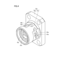
- FIG. 5 is a schematic perspective view showing the appearance of the piece member 14a.
- FIG. 6 is an exploded perspective view of the piece member 14a.
- FIG. 7 is a schematic cross-sectional view of the piece member 14a when a part of the piece member 14a is cut away.
- FIG. 8 is a schematic perspective view of the piece member 14a as viewed from the inner diameter side of the nut 12a.
- FIG. 9 and FIG. 10 are schematic perspective views showing the first member 31a and the second member 32a combined together.
- FIG. 9 and FIG. 10 are views seen from different angles.
- FIG. 11 is a schematic perspective view showing the first member 31a.
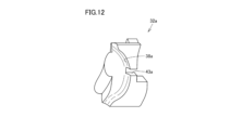
- FIG. 12 is a schematic perspective view showing the second member 32a.
- FIG. 13 is a schematic perspective view showing the third member 33a.
- the rolling balls 13a are also shown in FIG. 5, FIG. 7, and FIG. 8, and the first screw 42a is also shown in FIG. 9.
- the first member 31a is provided with a first groove 36a that constitutes part of the circulation path 29a.
- the first member 31a also has a first contact surface 37a that contacts the second member 32a when combined with the second member 32a.
- the second member 32a is provided with a second groove 38a that constitutes part of the circulation path 29a.
- the second member 32a has a second contact surface 39a that contacts the first member 31a when combined with the first member 31a.
- the shape of the second contact surface 39a corresponds to the shape of the first contact surface 37a.
- the first member 31a and the second member 32a are combined so that the first contact surface 37a and the second contact surface 39a are in contact with each other, thereby forming the circulation path 29a that is composed of the first groove 36a and the second groove 38a.
- the first member 31a is provided with a first mounting hole 41a for mounting the first member 31a to the nut 12a side.
- the first mounting hole 41a is a round hole.
- the first mounting hole 41a has a shape with a portion of a different diameter so that the body of the first mounting screw 42a passes through and the head is hooked.
- a flat head screw is used as the first screw 42a and the second screw 47a described later.
- the second member 32a is provided with an accommodation groove 43a for accommodating the protruding region 53a of the contact portion 52a of the grease supply member 34a described later.
- the grease supply member 34a is plate-shaped. More specifically, the grease supply member 34a is flat.
- the grease supply member 34a is also called an oil-containing member.
- the grease supply member 34a is composed of a member impregnated with lubricating oil, for example.
- the grease supply member 34a may be one that is made by heating and molding a porous sintered resin member and impregnating it with a lubricant.
- a solid lubricant may be used that is made by mixing a powder of a sintered resin member with a lubricant and heating and molding the mixture.
- the grease supply member 34a includes a flat plate portion 51a and a contact portion 52a exposed on the circulation path 29a side and in contact with the ball 13a.
- the flat plate portion 51a is polygonal when viewed in the thickness direction.
- the contact portion 52a has a protruding region 53a protruding from the flat plate portion 51a toward the circulation path 29a side.
- the ball 13a is greased, i.e., lubricating oil is supplied by seeping out from the protruding region 53a.
- the lubricating oil impregnated in the area of the flat plate portion 51a is gradually supplied to the protruding region 53a side.
- the protruding length L of the protruding region 53a is 30% or more and 70% or less of the diameter D of the ball 13a. In this embodiment, the protruding length L of the protruding region 53a is 40% or more and 60% or less of the diameter D of the ball 13a. (See Figures 5 and 6 in particular). In addition, in this embodiment, the length of the protruding region 53a protruding toward the circulation path 29a, as indicated by the arrow P in FIG. 7, is, for example, 40% to 60% of the protruding length L of the protruding region 53a in FIG. 6.
- the third member 33a holds the grease supply member 34a so as to cover the outer diameter side of the grease supply member 34a.
- the third member 33a is provided with a storage recess 45a for storing the grease supply member 34a.
- the shape of the storage recess 45a is provided so as to be recessed along the outer shape of the plate-shaped grease supply member 34a, mainly the outer shape of the flat plate portion 51a.
- the third member 33a is provided with a second mounting hole 46a for mounting the third member 33a to the nut 12a side.
- the second mounting hole 46a is a round hole.
- the second mounting hole 46a like the first mounting hole 41a, has a shape having a portion of a different diameter so that the body of the second mounting screw 47a passes through and the head is hooked.
- the third member 33a is provided with a third contact surface 48a that contacts the first contact surface 37a of the first member 31a during mounting.
- the first member 31a is attached to the nut 12a by a first screw 42a.
- the third member 33a is attached to the nut 12a by a second screw 47a.
- the second member 32a is sandwiched between the first member 31a and the third member 33a.
- the grease supply member 34a is sandwiched between the second member 32a and the third member 33a.
- the installation of the above-mentioned piece member 14a can be briefly explained as follows.
- the first member 31a and the second member 32a are combined so that the first contact surface 37a and the second contact surface 39a are in contact with each other, and the first member 31a is fixed to the nut 12a using the first screw 42a.
- the body of the first screw 42a is passed through the first mounting hole 41a, and the first screw 42a is attached using a screw hole provided in the nut 12a to fix the first member 31a.
- the oil supply member 34a is accommodated in the accommodation recess 45a, and the third member 33a is applied from the outer diameter side so that the protruding region 53a of the contact portion 52a is accommodated in the accommodation groove 43a of the second member 32a.
- the grease supply member 34a is placed from the outer diameter side so that the protruding region 53a of the contact portion 52a is accommodated in the accommodation groove 43a of the second member 32a, and the third member 33a is attached from the outer diameter side so that the grease supply member 34a is accommodated in the accommodation recess 45a.
- the grease supply member 34a is sandwiched between the second member 32a and the third member 33a in the radial direction.
- the third member 33a is fixed to the nut 12a using the second screw 47a so that the first contact surface 37a and the third contact surface 48a are in contact with each other.
- the body of the second screw 47a is passed through the second mounting hole 46a, and the second screw 47a is attached using the screw hole provided in the nut 12a to fix the third member 33a.
- the top member 14a is not composed of a single part, but is composed of a combination of the first member 31a, the second member 32a, the third member 33a, and the greasing member 34a.
- the circulation path 29a is formed by combining the first groove 36a and the second groove 38a. In this way, for the members other than the greasing member 34a, it is possible to select and combine members of appropriate materials and shapes according to the function required for the circulation path 29a and ease of installation.
- the greasing member 34a has a contact portion 52a that is exposed to the circulation path 29a and contacts the ball 13a, so that the contact portion 52a can graze the ball 13a passing through the circulation path 29a.
- the third member 33a is arranged to cover the outer diameter side of the grease supply member 34a, the grease supply member 34a is not exposed to the outer diameter side, and as a result, the grease supply member 34a can be prevented from drying out. Since the grease supply member 34a is held by the third member 33a, when replacing the grease supply member 34a, the third member 33a can be removed from the nut 12a. In this way, the grease supply member 34a can be replaced without removing the first member 31a and the second member 32a from the nut 12a, which reduces the risk of an increase in assembly man-hours and improves workability. As described above, according to the above-mentioned ball screw 10a, it is possible to improve workability while ensuring smooth rolling and circulation of the balls 13a for a long period of time.
- the greasing member 34a is plate-shaped. Therefore, the thickness direction of the greasing member 34a is arranged in the radial direction of the ball screw 10a, and a relatively large amount of lubricating oil can be impregnated into the greasing member 34a while preventing the volume from increasing particularly in the radial direction. In addition, the greasing member 34a can be easily handled.
- the grease supply member 34a is held by being sandwiched between the third member 33a and the second member 32a. This allows the position of the grease supply member 34a to be stably maintained within the piece member 14a. This allows the ball 13a to be greased more stably over a long period of time.
- the contact portion 52a has a protruding region 53a that protrudes toward the circulation path 29a.
- the second member 32a is provided with a storage groove 43a that houses the protruding region 53a.
- lubricating oil can be gradually exuded from the protruding region 53a to grease the ball 13a.
- the protruding region 53a since the protruding region 53a is housed in the storage groove 43a, the protruding region 53a can be stably held and the shifting of the grease supply position can be suppressed. Therefore, the ball 13a can be greased more reliably over a long period of time.
- the protruding length L of the protruding region 53a is 30% to 70% of the diameter D of the ball 13a. This allows the ball 13a and the protruding region 53a to come into contact more reliably. This allows the ball 13a to be greased more reliably.
- the third member 33a is provided with a storage recess 45a that stores the greasing member 34a. Therefore, the greasing member 34a can be fitted into the storage recess 45a provided in the third member 33a and stored therein, and the greasing member 34a can be held more stably. In addition, the third member 33a can be attached by fitting the greasing member 34a into the storage recess 45a, improving workability.
- the first member 31a and the third member 33a are attached to the nut 12a by screws 42a and 47a, respectively.
- the second member 32a is sandwiched between the first member 31a and the third member 33a. Therefore, the first member 31a and the third member 33a can be reliably fixed to the nut 12a by the screws 42a and 47a, and the first member 31a and the third member 33a can be removed by turning the screws 42a and 47a.
- the second member 32a is sandwiched between the first member 31a and the third member 33a, it can be more reliably fixed to the nut 12a side. In other words, by adopting such a configuration, it is possible to easily attach and detach the top member 14a. This makes it easy to replace the grease supply member 34a, etc. Therefore, it is possible to further improve workability.
- multiple piece members 14a are provided at intervals in the circumferential direction. Therefore, multiple balls 13a can be circulated smoothly by multiple piece members 14a. Therefore, balls 13a can be circulated more smoothly.
- the contact portion and the rolling surface of the ball are in contact with each other on the outer diameter side of the ball, but this is not limited thereto, and the contact portion and the rolling surface of the ball may be in contact with each other on one side in the axial direction of the ball.
- the grease supply member is plate-shaped, but this is not limited thereto, and the grease supply member may be, for example, block-shaped or spherical.
- first member and the third member are attached to the nut side with screws, but this is not limited thereto, and the first member and the third member may be attached to the nut side by, for example, a snap fit.
Landscapes
- Engineering & Computer Science (AREA)
- General Engineering & Computer Science (AREA)
- Mechanical Engineering (AREA)
- Transmission Devices (AREA)
Priority Applications (3)
| Application Number | Priority Date | Filing Date | Title |
|---|---|---|---|
| JP2024504257A JP7517667B1 (ja) | 2023-11-17 | 2023-11-17 | ボールねじ |
| PCT/JP2023/041416 WO2025104903A1 (ja) | 2023-11-17 | 2023-11-17 | ボールねじ |
| TW113101716A TW202521865A (zh) | 2023-11-17 | 2024-01-16 | 滾珠螺桿 |
Applications Claiming Priority (1)
| Application Number | Priority Date | Filing Date | Title |
|---|---|---|---|
| PCT/JP2023/041416 WO2025104903A1 (ja) | 2023-11-17 | 2023-11-17 | ボールねじ |
Publications (1)
| Publication Number | Publication Date |
|---|---|
| WO2025104903A1 true WO2025104903A1 (ja) | 2025-05-22 |
Family
ID=91895985
Family Applications (1)
| Application Number | Title | Priority Date | Filing Date |
|---|---|---|---|
| PCT/JP2023/041416 Pending WO2025104903A1 (ja) | 2023-11-17 | 2023-11-17 | ボールねじ |
Country Status (3)
| Country | Link |
|---|---|
| JP (1) | JP7517667B1 (https=) |
| TW (1) | TW202521865A (https=) |
| WO (1) | WO2025104903A1 (https=) |
Citations (4)
| Publication number | Priority date | Publication date | Assignee | Title |
|---|---|---|---|---|
| JP2015117780A (ja) * | 2013-12-19 | 2015-06-25 | 日本精工株式会社 | ボールねじ |
| DE202018103321U1 (de) * | 2018-06-13 | 2018-08-02 | Hiwin Technologies Corp. | Selbstschmierender Kugelgewindetrieb |
| JP2019196833A (ja) * | 2018-05-11 | 2019-11-14 | 株式会社ジェイテクト | ボールねじ機構及びステアリング装置 |
| JP2021032364A (ja) * | 2019-08-27 | 2021-03-01 | 日本ピストンリング株式会社 | ボール循環部品 |
-
2023
- 2023-11-17 WO PCT/JP2023/041416 patent/WO2025104903A1/ja active Pending
- 2023-11-17 JP JP2024504257A patent/JP7517667B1/ja active Active
-
2024
- 2024-01-16 TW TW113101716A patent/TW202521865A/zh unknown
Patent Citations (4)
| Publication number | Priority date | Publication date | Assignee | Title |
|---|---|---|---|---|
| JP2015117780A (ja) * | 2013-12-19 | 2015-06-25 | 日本精工株式会社 | ボールねじ |
| JP2019196833A (ja) * | 2018-05-11 | 2019-11-14 | 株式会社ジェイテクト | ボールねじ機構及びステアリング装置 |
| DE202018103321U1 (de) * | 2018-06-13 | 2018-08-02 | Hiwin Technologies Corp. | Selbstschmierender Kugelgewindetrieb |
| JP2021032364A (ja) * | 2019-08-27 | 2021-03-01 | 日本ピストンリング株式会社 | ボール循環部品 |
Also Published As
| Publication number | Publication date |
|---|---|
| JP7517667B1 (ja) | 2024-07-17 |
| TW202521865A (zh) | 2025-06-01 |
| JPWO2025104903A1 (https=) | 2025-05-22 |
Similar Documents
| Publication | Publication Date | Title |
|---|---|---|
| US8025128B2 (en) | Ball screw lubricative sealing device | |
| US7059777B2 (en) | Assembly for ball bearing with double raceway and method of manufacturing ball bearing with double raceway | |
| EP2613063A1 (en) | Linear motion guide device | |
| US20120321237A1 (en) | Conical roller cage | |
| EP3508742A1 (en) | Linear guide | |
| US20180195591A1 (en) | Screw apparatus | |
| US20160097425A1 (en) | Segmented outer ring for a bearing for mitigating torque degradation | |
| JP7517667B1 (ja) | ボールねじ | |
| JP4989432B2 (ja) | 運動装置 | |
| US9400047B2 (en) | Self lubricating linear motion guided screw assembly | |
| US20170184153A1 (en) | Rolling Bearing | |
| US9964149B2 (en) | Cage for a ball bearing provided with a wire and added interposed parts | |
| JP2019100416A (ja) | 4点接触玉軸受およびこれを備えるボールねじ装置 | |
| KR102300419B1 (ko) | 볼나사 | |
| CN106931038B (zh) | 包括设置有线材的保持架和密封件的轴承 | |
| JP4945413B2 (ja) | オプション部品付き運動装置及びその製造方法 | |
| JP7119358B2 (ja) | 防炭剤の浸入防止軸受構造およびこれを備える4点接触玉軸受並びにボールねじ装置 | |
| JPH0328616B2 (https=) | ||
| JP7802439B2 (ja) | ボールねじ装置 | |
| US3838897A (en) | Curvilinear bearing assembly | |
| JPWO2019138949A1 (ja) | 滑り軸受 | |
| JP5168205B2 (ja) | ボールねじ装置 | |
| JPH0328617B2 (https=) | ||
| JP3189087U (ja) | 連設軸受筒 | |
| JP2004169789A (ja) | 間座入りボールねじおよびその組立方法 |
Legal Events
| Date | Code | Title | Description |
|---|---|---|---|
| ENP | Entry into the national phase |
Ref document number: 2024504257 Country of ref document: JP Kind code of ref document: A |
|
| WWE | Wipo information: entry into national phase |
Ref document number: 2024504257 Country of ref document: JP |
|
| 121 | Ep: the epo has been informed by wipo that ep was designated in this application |
Ref document number: 23958905 Country of ref document: EP Kind code of ref document: A1 |