WO2025100367A1 - 通信装置、通信装置の制御方法及びプログラム - Google Patents
通信装置、通信装置の制御方法及びプログラム Download PDFInfo
- Publication number
- WO2025100367A1 WO2025100367A1 PCT/JP2024/039120 JP2024039120W WO2025100367A1 WO 2025100367 A1 WO2025100367 A1 WO 2025100367A1 JP 2024039120 W JP2024039120 W JP 2024039120W WO 2025100367 A1 WO2025100367 A1 WO 2025100367A1
- Authority
- WO
- WIPO (PCT)
- Prior art keywords
- file
- video file
- external device
- chunk
- imaging device
- Prior art date
- Legal status (The legal status is an assumption and is not a legal conclusion. Google has not performed a legal analysis and makes no representation as to the accuracy of the status listed.)
- Pending
Links
Images









Classifications
-
- H—ELECTRICITY
- H04—ELECTRIC COMMUNICATION TECHNIQUE
- H04N—PICTORIAL COMMUNICATION, e.g. TELEVISION
- H04N21/00—Selective content distribution, e.g. interactive television or video on demand [VOD]
- H04N21/40—Client devices specifically adapted for the reception of or interaction with content, e.g. set-top-box [STB]; Operations thereof
- H04N21/43—Processing of content or additional data, e.g. demultiplexing additional data from a digital video stream; Elementary client operations, e.g. monitoring of home network or synchronising decoder's clock; Client middleware
- H04N21/436—Interfacing a local distribution network, e.g. communicating with another STB or one or more peripheral devices inside the home
-
- H—ELECTRICITY
- H04—ELECTRIC COMMUNICATION TECHNIQUE
- H04N—PICTORIAL COMMUNICATION, e.g. TELEVISION
- H04N5/00—Details of television systems
- H04N5/76—Television signal recording
- H04N5/765—Interface circuits between an apparatus for recording and another apparatus
-
- H—ELECTRICITY
- H04—ELECTRIC COMMUNICATION TECHNIQUE
- H04N—PICTORIAL COMMUNICATION, e.g. TELEVISION
- H04N5/00—Details of television systems
- H04N5/76—Television signal recording
- H04N5/91—Television signal processing therefor
Definitions
- the present invention relates to a communication device, a control method for a communication device, and a program.
- Patent Document 1 a technology in which an imaging device such as a digital video camera is equipped with a wireless communication function, and a video file in which a video captured by the imaging device is divided and recorded at predetermined time intervals (hereinafter also referred to as chunk recording) is transmitted to an external device (Patent Document 1).
- an imaging device such as a digital video camera
- a video file in which a video captured by the imaging device is divided and recorded at predetermined time intervals hereinafter also referred to as chunk recording
- Video files generated by chunk recording (hereafter also referred to as chunk video files) can be treated as a single video by combining them on the destination external device. For this reason, the destination external device must have the entire series of files from the first chunk video file to the last chunk video file; if any chunk video files are missing, the files cannot be combined correctly on the external device.
- the present invention was made in consideration of the above problems, and its purpose is to realize a technology that can prevent a shortage of files necessary for combining time-series data, such as video files, when transferring the data to an external device.
- the communication device of the present invention has the following configuration. That is, the device has a communication means for communicating with an external device, a control means for controlling, when a file is generated in a first external device, to acquire the file from the first external device via the communication means, and a transfer means for transferring the file to a second external device via the communication means when the file is acquired, and the control means is characterized in that, when a first split file is generated in the first external device as a split file that is generated sequentially by dividing continuous time series data, the control means controls whether or not to acquire the first split file from the first external device depending on the acquisition status of split files that precede the first split file from the beginning of the time series data.
- FIG. 1 is a conceptual diagram showing an example of a system configuration according to a first embodiment.
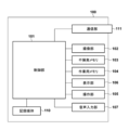
- FIG. 1 is a block diagram showing an example of the arrangement of an imaging apparatus according to a first embodiment.
- FIG. 1 is a diagram showing an example of the appearance of an imaging device according to a first embodiment;
- FIG. 1 is a block diagram showing an example of the configuration of a communication device according to a first embodiment.
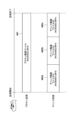
- FIG. 1 is a diagram for explaining chunk recording in the first embodiment;
- FIG. 1 is a conceptual diagram showing an example of a system configuration according to a first embodiment.
- FIG. 1 is a block diagram showing an example of the arrangement of an imaging apparatus according to a first embodiment.
- FIG. 1 is a diagram showing an example of the appearance of an imaging device according to a first embodiment;
- FIG. 1 is a block diagram showing an example of the configuration of a communication device according to a first embodiment.
- FIG. 1 is a diagram for explaining chunk recording in the first embodiment;
- FIG. 1 is a
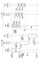
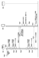
- FIG. 1 is a sequence diagram (1) showing an example of a file transfer process during proxy recording and chunk recording in the first embodiment
- FIG. 1 is a sequence diagram (1) showing an example of an operation when chunk recording is started after automatic shooting and transfer processing is started in the first embodiment
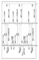
- FIG. 2 is a sequence diagram (2) showing an example of an operation when chunk recording is started after the start of the automatic shooting and transfer process in the first embodiment
- FIG. 1 is a sequence diagram (1) showing an example of an operation when automatic shooting transfer is started after chunk recording is started in the first embodiment.
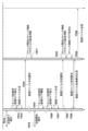
- FIG. 2 is a sequence diagram (2) showing an example of an operation when automatic shooting transfer is started after chunk recording is started in the first embodiment;
- FIG. 11 is a sequence diagram showing an example of an operation when an automatic transfer process is executed in the second embodiment;
- 13 is a screen example showing a warning message when the automatic image transfer function is executed during chunk recording in the second embodiment.
- the mobile application receives a recording completion notification of a video file from the imaging device using, for example, a PTP/IP (Picture Transfer Protocol over Internet Protocol) protocol. Then, the video file is acquired and the acquired video file is transferred to an external FTP server.
- PTP/IP Picture Transfer Protocol over Internet Protocol
- the user can automatically deliver the captured files to an external delivery destination without having to perform an operation to select the files.
- chunk video files generated by chunk recording are generally treated as one video by combining them at the delivery destination. For this reason, at the time of delivery, it is necessary that the entire series of files from the first chunk video file to the last chunk video file are available. If the delivery is made with some chunk video files missing, the files cannot be combined properly at the delivery destination.
- the automatic shooting and transfer function transitions to a state in which it can receive a recording completion notification of the video file from the imaging device. After that, when the communication device receives a recording completion notification of the video file from the imaging device, it acquires the video file from the imaging device and transfers it to an external FTP server.
- the processing sequence of the automatic shooting and transfer function is also applied to chunk recording, for example, there may be a case where chunk recording has already started on the imaging device side at the time the function is enabled. In this case, the communication device cannot receive a recording completion notification of the chunk video file recorded before the function was enabled from the imaging device. If the video file for which the recording completion notification has been received is simply acquired and transferred to an external device, the video will be delivered without the previous chunk video files necessary for combining at the delivery destination.
- a video file is transferred, but this embodiment is not limited to video, and can be applied to cases where chunk recording is applied to time-series data including video and audio data.
- the chunk video file corresponds to split files that are generated sequentially by splitting continuous time-series data.
- Fig. 1 An example of the configuration of a system in the first embodiment will be described with reference to Fig. 1.
- 100 is an imaging device such as a digital video camera. As described later, the imaging device may be any other device as long as it has a configuration capable of acquiring time-series data such as video.
- 200 is a communication device such as a mobile terminal having a communication function, such as a smartphone.
- 300 is a server as an example of an image storage device, and may be installed at a connection destination via a communication network such as the Internet.
- the imaging device 100 and the communication device 200 are connected via a connection means such as a wired cable or Wi-Fi, and can perform wired or wireless communication.
- the imaging device 100 can, for example, transfer a video file generated by the imaging device 100 to the communication device 200.
- the communication device 200 and the server 300 can communicate via a communication means such as a wireless LAN or mobile communication.
- the communication device 200 can, for example, transfer information stored in the communication device 200 to the server 300 using a communication protocol such as FTP.
- FTP communication protocol
- the system configuration is not limited to the above example, and for example, the imaging device 100, the communication device 200, and the server 300 may be connected to the same network via an access point without using mobile communication, and file transfer processing between the devices may be realized.
- Imaging device 100 An example of the configuration of an imaging device 100 according to the present embodiment will be described with reference to Fig. 2A.
- Imaging devices include, for example, portable media players, so-called tablet devices, personal computers, and the like.
- the control unit 101 includes one or more processors, and controls each part of the imaging device 100 (the entire imaging device) according to input signals and programs described below. Note that instead of the control unit 101 controlling the entire device, the entire device may be controlled by multiple hardware devices sharing the processing.
- the imaging unit 102 is composed of, for example, an optical lens unit, an optical system that controls the aperture, zoom, focus, etc., and an imaging element for converting the light (image) introduced through the optical lens unit into an electrical image signal.
- an imaging element a CMOS (Complementary Metal Oxide Semiconductor) or a CCD (Charge Coupled Device) is generally used.
- the imaging unit 102 converts the subject light imaged by the lens included in the imaging unit 102 into an electrical signal using the imaging element, performs noise reduction processing, etc., and outputs the digital data as video data.
- the video data is recorded, for example, on the recording medium 110.
- the non-volatile memory 103 is a non-volatile memory that can be electrically erased and recorded, and stores the programs executed by the control unit 101, which will be described later.
- the working memory 104 is used as a buffer memory for temporarily storing video data captured by the imaging unit 102, a memory for displaying video on the display unit 106, a working area for the control unit 101, etc.
- the working memory 104 may be a volatile memory.
- the operation unit 105 is used to receive instructions from the user for the imaging device 100.
- the operation unit 105 includes, for example, a power button that allows the user to instruct the imaging device 100 to be powered on/off, a release switch that instructs the user to start/stop shooting, and a playback button that instructs the user to play back video data. It also includes operation members such as a dedicated connection button for starting communication with an external device via the communication unit 111 described below.
- the operation unit 105 also includes a touch panel formed on the display unit 106 described below.
- the display unit 106 displays the viewfinder image during shooting, displays shot video data, displays text for interactive operation, etc. Note that the display unit 106 does not necessarily have to be built into the imaging device 100.
- the imaging device 100 can be connected to an internal or external display unit 106, and it is sufficient that the imaging device 100 has at least a display control function for controlling the display of the display unit 106.
- the audio input unit 107 is a device for inputting audio information, and the audio data converted from the audio information by the audio input unit 107 is recorded on the recording medium 110 in an audio file format.
- the recording medium 110 can record the video data output from the imaging unit 102 and the audio data output from the audio input unit 107.
- the recording medium 110 of this embodiment has, for example, two slots.
- the control unit 101 calculates the video data from the imaging unit 202, it records a high-resolution video file (hereinafter, a main video file) specified by the user, such as the resolution of an imaging sensor (not shown) (included in the imaging unit 202), in the first slot of the recording medium 110.
- the control unit 101 records a low-resolution or low-bitrate video file (hereinafter, a proxy video file) or a chunk video file recorded in chunks, which are transmitted from the communication unit 111 to the communication device 200 via a network, in the second slot of the recording medium 110.
- the recording medium 110 may be configured to be detachable from the imaging device 100, or may be built into the imaging device 100. In other words, it is sufficient that the imaging device 100 has at least a means for accessing the recording medium 110.
- the communication unit 111 is an interface for connecting to an external device.
- the imaging device 100 of this embodiment can exchange data with an external device via the communication unit 111.
- video data generated by the control unit 101 and audio data generated by the audio input unit 107 can be transmitted to an external device via the communication unit 111.
- the communication unit 111 includes an interface for communicating with an external device via a so-called wireless LAN in accordance with the IEEE802.11 standard.
- the communication unit 111 also includes a USB interface via a Universal Serial Bus (USB) cable with the external device.
- the control unit 101 realizes wireless and wired communication with the external device by controlling the communication unit 311.
- the communication unit 111 of the imaging device 100 in this embodiment can operate in an access point mode (hereinafter, AP mode) in which it operates as an access point in infrastructure mode. Furthermore, the communication unit 111 can operate in a client mode (hereinafter, CL mode) in which it operates as a client in infrastructure mode. Then, by operating the communication unit 111 in CL mode, the imaging device 100 in this embodiment can operate as a CL device in infrastructure mode. When the imaging device 100 operates as a CL device, it can connect to a surrounding AP device and participate in a network formed by the AP device.
- AP mode access point mode
- CL mode client mode
- the imaging device 100 in this embodiment can operate as a CL device in infrastructure mode.
- the imaging device 100 When the imaging device 100 operates as a CL device, it can connect to a surrounding AP device and participate in a network formed by the AP device.
- the imaging device 100 in this embodiment can operate as a simple AP (hereinafter, simple AP), which is a type of AP but has more limited functions.
- simple AP simple AP
- the imaging device 100 forms a network by itself.
- the peripheral devices of the imaging device 100 recognize the imaging device 100 as an AP device and can participate in the network formed by the imaging device 100.
- the program for operating the imaging device 100 is stored in the non-volatile memory 103.
- the imaging device 100 is a type of AP, it may be a simple AP that does not have a gateway function for transferring data received from a CL device to an Internet provider or the like. In this case, even if the imaging device 100 receives data from other devices participating in the network it has formed, it cannot transfer the data to a network such as the Internet.
- the release switch 105a, zoom lever 105b, playback button 105c, and touch panel 105d are operation members included in the operation unit 105 described above.
- the display unit 106 displays a video obtained as a result of imaging by the imaging unit 102.
- a configuration example of the communication device 200 of the present embodiment will be described with reference to Fig. 3.
- the communication device 200 is not limited to this.
- the communication device 200 may be a digital video camera with a wireless function, a tablet device, a personal computer, or the like.
- the control unit 201 includes one or more processors, and controls each part of the communication device 200 (the entire communication device) according to input signals and programs described below. Note that instead of the control unit 201 controlling the entire device, the entire device may be controlled by multiple hardware devices sharing the processing.
- the imaging unit 202 converts the subject light imaged by the lens included in the imaging unit 202 into an electrical signal, performs noise reduction processing, etc., and outputs the digital data as video data. After the captured video data is stored in a buffer memory, a predetermined calculation is performed by the control unit 201 and the data is recorded on the recording medium 210.
- the non-volatile memory 203 is a non-volatile memory that can be electrically erased and recorded.
- an OS operating system
- the non-volatile memory 203 also stores a transfer application (hereinafter, transfer app) that allows the communication device 200 to transfer data between the imaging device 100 and the server 300.
- transfer app a transfer application
- file management application hereinafter, file management app
- image management app an image management application
- the working memory 204 is used as an image display memory for the display unit 206, a working area for the control unit 201, etc. In this embodiment, it temporarily stores video files received from the imaging device 100 when they are transferred to the server 300.
- the working memory 204 may be a volatile memory.
- the operation unit 205 is used to receive instructions from the user for the communication device 200.
- the operation unit 205 includes, for example, an operation member such as a power button that allows the user to instruct the communication device 200 to be turned on/off, and a touch panel formed on the display unit 206.
- the display unit 206 displays video data, displays characters for interactive operations, and the like. Note that the display unit 206 does not necessarily have to be included in the communication device 200.
- the communication device 200 only needs to be able to connect to the display unit 206 and have at least a display control function for controlling the display of the display unit 206.
- the recording medium 210 can record image data output from the imaging unit 202.
- the recording medium 210 may be configured to be detachable from the communication device 200, or may be built into the communication device 200. In other words, the communication device 200 only needs to have at least a means for accessing the recording medium 210.
- the communication unit 211 also includes a USB interface via a Universal Serial Bus (USB) cable to connect to an external device.
- USB Universal Serial Bus
- the communication unit 211 can include a wireless communication module such as an infrared communication module, a Bluetooth (registered trademark) communication module, or a Wireless USB.
- the public network connection unit 213 is an interface used when performing public wireless communication.
- the communication device 200 can communicate with other devices via the public network connection unit 213.
- the control unit 201 realizes the call by inputting and outputting audio signals via the microphone 214 and speaker 215.
- the first mode of recording a video file is proxy recording.
- the imaging device 100 records a proxy video file that is recorded with the same recording time as the main video file.
- 401 indicates a proxy video file in which the video recording time is from the start of recording to the end of recording.
- proxy recording is a recording mode in which one proxy video file is generated from the start of recording to the end of recording.
- the imaging device 100 when generating the file name of the proxy video file 401, the imaging device 100, for example, sets the fourth character following "MVI" to "P", followed by a file number and an extension.
- the imaging device 100 sets the file name of the proxy video file to, for example, "MVIP0001.MP4".
- the imaging device 100 records proxy video files that are divided into small pieces at the timing when a predetermined time has passed during recording.
- the imaging device 100 generates a new chunk video file when a predetermined time has passed since the start of recording or the timing when the previous chunk video file was generated.
- the imaging device 100 generates chunk video file 402a when 30 seconds have passed since the start of recording.
- the imaging device 100 generates chunk video file 402b when 30 seconds have passed since the generation of chunk video file 402a.
- the imaging device 100 records chunk video files up to 402b at 30-second intervals.
- the imaging device 100 When the user presses release switch 105a to end recording, the imaging device 100 generates chunk video file 402c from the timing when the previous chunk video file 402b was generated to the time when recording ended.
- the next chunk video file 402b to be generated is assigned a character indicating that it is an intermediate video file.
- the imaging device 100 assigns the fourth character following "MVI" to be "D".
- the file name of the next chunk video to be generated will be "MVID0002.MP4".
- the last chunk video file 402c to be generated is assigned a character indicating that it is the last video file (when recording is completed). For example, the imaging device 100 assigns "E” as the fourth character following "MVI". In this case, the file name of the last chunk video file to be generated will be "MVIE0003.MP4".
- a communication device or the like that acquires the file can determine whether the recording mode is chunk recording or proxy recording, which will be described later.
- the fourth character makes it easy to identify whether the target video file is at the beginning, middle, or end.
- FIG. 4B the advantages of chunk recording will be described using an example in which a video file is transferred from the imaging device 100 to the server 300 via the communication device 200.
- the imaging device 100 cannot transmit the video file being recorded, and so begins transmitting the proxy video after recording is completed.
- the time required to transmit the proxy video file 401 is added to the time required to record the proxy video file 401.
- 405 in FIG. 4B indicates the time required from the start of recording the proxy video to the completion of transfer of the proxy video file 401.
- the imaging device 100 can sequentially transmit chunk video files that have already been generated, even while recording a video. For example, once chunk video file 402a has been generated (when recording to that file has been completed), chunk video file 402a can be transferred even while the imaging device 100 is recording. In the example of FIG. 4B, the imaging device 100 can start transferring the video file an amount of difference time 406 earlier than the recording time of proxy video file 401. When transferring a video file using chunk recording, the time from the start of recording to the completion of transmission of the video file is 407. In this way, there is an advantage in that the transfer time 407 of chunk recording can be completed an amount of difference time 408 earlier than the transfer time 405 of proxy recording.
- Fig. 5AA, Fig. 5AB, Fig. 5BC, and Fig. 5BD show a schematic display state of the operation screen of the transfer app.
- the transfer app displays, for example, a function selection screen 501, a list screen of contents in the camera, and an automatic shooting transfer screen 504 in response to a user operation.
- the function selection screen 501 includes, for example, an in-camera content list display button 502 and an automatic shooting transfer button 503.
- the in-camera content list display button 502 is a button for acquiring content (e.g., a video file) recorded in the imaging device 100 and transitioning to a camera content list screen described later.
- the automatic shooting transfer button 503 is a button for transitioning to an automatic shooting transfer screen 504 for transferring content received from the imaging device 100 to another device (e.g., the server 300).
- the communication device 200 transitions to a camera content list screen (not shown).
- the camera content list screen is a screen that displays a list of files recorded in the imaging device 100.
- the communication device 200 can display the acquired content in a list using, for example, a known method.
- the automatic capture and transfer button 503 is pressed, the communication device 200 transitions to an automatic capture and transfer screen 504.
- the communication device 200 displays the files transferred from the imaging device 100 to the server 300 via the communication device 200.
- the communication device 200 transitions to the automatic shooting and transfer screen 504, it is in a state in which it can receive a video file generation notification from the imaging device 100.
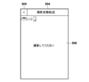
- 505 is a button for returning to the previous screen.
- 506 is the initial screen of the automatic shooting and transfer screen 504, which is displayed while no transfer has been made (when no transferred content exists).
- the communication device 200 displays the state when a proxy video file recorded by the imaging device 100 is transferred to an external device (e.g., server 300). Specifically, the communication device 200 displays information about the video file being transferred in the display area of current transfer content status 507.
- the information about the video file being transferred includes, for example, a thumbnail image and a file name.
- Information related to these video files is included in, for example, the data in the video file generation notification from the imaging device 100, and the communication device 200 can display this information by referring to the data in the video file generation notification.
- the communication device 200 also displays a character string and a progress bar indicating the progress of the content transfer.
- the progress is updated depending on, for example, whether the video file from the imaging device 100 is being acquired, or whether it is being transmitted to the server 300.
- the length of the progress bar is updated depending on the data size of the video file acquired from the imaging device 100, and the data size transmitted to the server 300.
- the communication device 200 displays a list of information about the video files that were transferred after transitioning to the automatic shooting transfer screen 504, in the display area of the transfer content list 508.
- the display of information about each video file includes a thumbnail image, file name, and a status icon indicating the transfer progress.
- the status icon indicates, for example, whether the transfer is in progress or has been completed.
- the communication device 200 displays information about "MVIP0001.MP4" in the transfer content list 508 along with an icon indicating that the transfer has been completed, and information about "MVIP0002.MP4" along with an icon indicating that the transfer is in progress.
- the communication device 200 displays the state when the chunk video file recorded by the imaging device 100 is transferred to an external device. Note that the contents displayed in the current transfer content status 507 and the transfer content list 508 are the same as those in FIG. 5BC. As shown in FIG. 5BD, the chunk video files generated by the chunk recording are transferred sequentially.
- Figs. 6A-6B a process sequence of a process (automatic transfer process) in which a transfer application of the communication device 200 automatically transfers a video file recorded by the imaging device 100 to the server 300 will be described.
- the sequence of the automatic transfer process shown in Figs. 6A-6B shows a process after the automatic shooting transfer screen 504 is displayed on the communication device 200 and the communication device 200 is in a state in which it is possible to receive a video file generation notification from the imaging device 100.
- the process described with the imaging device 100 as the processing subject is realized by the control unit 101 expanding and executing a program stored in the non-volatile memory 103 in the working memory 104 and controlling each part of the imaging device 100.
- the process described with the communication device 100 as the processing subject is realized by the control unit 201 expanding and executing a program stored in the non-volatile memory 203 in the working memory 204 and controlling each part of the communication device 200.
- T601 when the imaging device 100 receives a recording start operation from the user in a state where the proxy recording setting is enabled, the imaging device 100 starts proxy recording.
- T602 when the imaging device 100 receives a recording stop operation from the user, the imaging device 100 generates a proxy video file in T603.
- T604 the imaging device 100 transmits a video file generation notification for the proxy video to the communication device 200.
- the video file generation notification is a message notifying the communication device 200 that a video file has been generated.
- T605 when the communication device 200 receives the video file generation notification, the communication device 200 transmits a video file acquisition request to the imaging device 100. Thereafter, the communication device 200 acquires the video file in response to the video file acquisition request transmitted from the imaging device 100.
- the communication device 200 transmits the video file acquired from the imaging device 100 to the server 300.
- the proxy video file recorded by the imaging device 100 is transferred to the server 300 via the communication device 200.
- the imaging device 100 starts a periodic timer for chunk recording that fires periodically when a specified period of time has elapsed in order to generate a video file divided at each specified time interval specified by the user.
- the imaging device 100 detects that the periodic timer for chunk recording has fired.
- the imaging device 100 generates a chunked video file (including a video of a predetermined length of time).
- the imaging device 100 transmits a video file generation notification for the chunked video to the communication device 200.
- This video file generation notification is a message notifying that individual chunked video files have been generated.
- the generated video file is the first chunked video file. Therefore, the imaging device 100 sets the file name of the chunked video file to "MVIB0001.MP4".
- the communication device 200 receives the video file generation notification.
- the communication device 200 transmits a video file acquisition request to the imaging device 100.
- the communication device 200 acquires the chunked video file in response to the video file acquisition request from the imaging device 100.
- the communication device 200 transmits the chunked video file acquired from the imaging device 100 to the server 300.
- the imaging device 100 When the imaging device 100 detects again the firing of the chunk recording period timer at T614, it generates a chunk video file (including a video of a predetermined length of time) at T615. Then, at T616, the imaging device 100 transmits a generation notification of the generated chunk video file to the communication device 200. At the time of T615, the generated video file is an intermediate chunk video file (not the first chunk video file). Therefore, the imaging device 100 sets the file name of the chunk video to "MVID0002.MP4".
- the communication device 200 receives the generation notification of the video file, it transmits a request to acquire the video file to the imaging device 100. The communication device 200 acquires the chunk video file in response to the video file acquisition request from the imaging device 100. At T618, the communication device 200 transmits the chunk video file acquired from the imaging device 100 to the server 300.
- the imaging device 100 When the imaging device 100 receives a recording stop operation from the user at T619, it stops the periodic timer for chunk recording at T620. At T621, the imaging device 100 generates a proxy video file. At T622, the imaging device 100 transmits a generation notification of the generated proxy video file to the communication device 200.
- the chunked video file to be generated will be the last chunked video file, so the imaging device 100 sets the file name of the chunked video file to "MVIE0003.MP4".
- the communication device 200 receives a notification of the generation of the video file. Thereafter, the communication device 100 transmits a request to acquire the video file to the imaging device 100, and acquires the chunked video file in response to the video file acquisition request from the imaging device 100.
- the communication device 200 transmits the video file acquired from the imaging device 100 to the server 300. Through this series of processes, a series of chunked video files generated by the imaging device 100 can be transferred to the server 300 via the communication device 200.
- the communication device 200 will sequentially receive the generation notification of the intermediate chunk video files from the imaging device 100 without receiving the generation notification of the first chunk video file.
- the communication device 200 sequentially acquires the corresponding chunk video files based on the received generation notification and transfers them to the server 300, the intermediate and subsequent chunk video files are transferred to the server 300. In other words, the previous chunk video files to be combined are not transferred to the server 300.
- the automatic transfer process of this embodiment includes an operation to prevent the transfer of the intermediate and subsequent chunk video files if the previous chunk video files to be combined have not been transferred.
- a process of determining whether a video file should be transferred based on the type of the generated chunk video file and a flag indicating whether the chunks are consecutive will be described as an example.
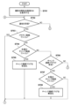
- FIGS. 7A-7B show a series of operations in the automatic transfer process executed in communication device 200.
- the automatic transfer process according to this embodiment is realized by control unit 201 expanding a program stored in non-volatile memory 203 into working memory 204, executing it, and controlling each part of communication device 200.
- the operations shown in FIGS. 7A-7B are initiated in response to, for example, pressing automatic capture transfer button 503 on function selection screen 501.
- the control unit 201 determines whether the video file indicated in the received generation notification is a proxy video file.
- the control unit 201 determines the type of video file based on the file name of the video file included in the received generation notification. If the type of video file included in the file name indicates a proxy video file, the control unit 201 determines that the video file is a proxy video file. If the control unit 201 determines that the video file is a proxy video file, the process proceeds to S709; otherwise, the process proceeds to S704. More specifically, the control unit 201 determines whether the video file is a proxy video file based on, for example, whether the fourth character following "MVI" in the video file name is a "P".
- the control unit 201 determines whether the video file indicated in the received generation notification is the first chunk video file.
- the control unit 201 determines the type of chunk video file based on the file name of the video file included in the received generation notification. If the type of chunk video file included in the file name indicates the first chunk video file, the control unit 201 proceeds to S705. On the other hand, if the video file for which the control unit 201 received the generation notification is other than the first chunk video file, the control unit 201 proceeds to S706. More specifically, the control unit 201 determines whether the video file is the first chunk video file based on whether the fourth character following "MVI" in the video file name is "B".
- the chunk succession flag is a flag that indicates whether the series of chunk video files to be combined have been transferred successfully from the first chunk video file. Depending on whether this flag is enabled, it is determined whether the intermediate or subsequent chunk video files received should be transferred.
- the chunk succession flag also essentially indicates whether "obtaining has been successful from the first chunk video file.” Therefore, the communication device 100 can also determine whether to obtain chunk video files from the middle onwards, depending on whether this flag is valid.
- control unit 201 determines whether the chunk succession flag is valid, and if it is valid (because the chunk video file should be transferred), the process proceeds to S707. On the other hand, if the chunk succession flag is not valid (because the chunk video file should not be transferred), the control unit 201 proceeds to S711.
- the control unit 201 determines whether the video file indicated in the generation notification is the last chunk video file. For example, the control unit 201 determines the type of chunk video file based on the file name included in the received generation notification. If the type of chunk video file indicates the last chunk video file, the control unit 201 advances the process to S708. On the other hand, if the video file for which the control unit 201 received the generation notification is not the last chunk video file, the control unit 201 advances the process to S709. More specifically, the control unit 201 determines whether the video file is the last chunk video file based on whether the fourth character following "MVI" in the video file name is "E". In S708, the control unit 201 disables the chunk succession flag (if the file name indicates the last chunk video file) and advances the process to S709.
- the control unit 201 determines whether the video file indicated in the generation notification is the last chunk video file. For example, the control unit 201 determines the type of chunk video file based on the file name included in the received generation notification. If the type of chunk
- control unit 201 transmits a video file acquisition request to the imaging device 100 in order to acquire the video file corresponding to the received generation notification, and acquires the video file in response to the video file acquisition request from the imaging device 100.
- control unit 201 transmits the video file acquired from the imaging device 100 to the server 300.
- the control unit 201 determines whether an operation to end automatic shooting transfer has been received (by pressing the back button 505 arranged on the automatic shooting transfer screen 504). If the control unit 201 determines that the operation to end has been received, the process proceeds to S712, otherwise the process returns to S702. In S712, the control unit 210 disables the chunk contact flag, and in S713, the control unit 201 ends the automatic shooting transfer function by displaying the function selection screen 501. As described above, by using the type of chunk video file and the chunk succession flag to determine whether previous chunk video files to be combined have been transferred, it is possible to prevent intermediate or subsequent chunk video files from being transferred.
- the communication device 200 accepts a user's press of the automatic capture and transfer button 503 on the function selection screen 501.
- the communication device 200 displays the automatic capture and transfer screen 504 (as shown in S701).
- the communication device 200 transitions to a state in which it waits for a notification from the imaging device 100 until it accepts an operation by the user to end the automatic capture and transfer (by the determination process in S711). Note that, although the example shown in Figures 8A-8B shows an example in which the communication device 200 simply enters a standby state in T803, the communication device 200 may notify the imaging device 100 that it has entered a standby state due to the automatic capture and transfer function.
- the imaging device 100 in a state in which the imaging device 100 is set to execute chunk recording, receives a recording start operation from the user and starts chunk recording.
- the imaging device 100 starts a periodic timer for chunk recording that fires periodically when a user-specified predetermined time has elapsed in order to generate a video file divided at each predetermined time specified by the user.
- the imaging device 100 When the chunk recording periodic timer fires at T806, the imaging device 100 generates a chunk video file at T807. At T808, the imaging device 100 transmits a generation notification of the generated video file to the communication device 200. At this time, since the generated video file is the first chunk video file, the imaging device 100 generates a generation notification of the video file indicating that the file name is "MVIB0001.MP4".
- the communication device 200 when the communication device 200 receives a video file generation notification from the imaging device 100, the communication device 200 references the video file name and determines that the video file is the first chunk video file (by the determination processes of S703 and S704). At T810, the communication device 200 enables the chunk continuation flag (as shown in S705).
- the communication device 200 transmits a request to acquire a video file to the imaging device 100 (as shown in S709), and acquires the video file in response to the video file acquisition request from the imaging device.
- the communication device 200 transmits the video file acquired from the imaging device 100 to the server 300 (as shown in S710), and returns to a state of waiting for a notification from the imaging device 100 again (by the determination process shown in S711).
- the imaging device 100 When the (next) chunk recording period timer fires in the imaging device 100 at T813, the imaging device 100 generates a chunk video file at T814. At T815, the imaging device 100 transmits a generation notification of the generated chunk video file to the communication device 200. At this time, since the generated video file is an intermediate chunk video file, the imaging device 100 generates a generation notification of the video file indicating that the file name is "MVID0002.MP4".
- communication device 200 when communication device 200 receives a video file generation notification, it references the video file name and determines (by the determination processes of S703 and S704) that it is not the first chunk video file. Next, communication device 200 determines whether the chunk continuation flag is enabled (as shown in S706), and determines that the chunk continuation flag is enabled based on the processing result at T810. Furthermore, communication device 200 references the video file name and determines (as shown in S707) that it is not the last chunk video file.
- the communication device 200 transmits a request to acquire the video file to the imaging device 100 (as shown in S709), and acquires the video file in response to the video file acquisition request from the imaging device.
- the communication device 200 transmits the video file acquired from the imaging device 100 to the server 300 (as shown in S710), and returns to a state of waiting for a notification from the imaging device 100 again (by the determination process shown in S711).
- the imaging device 100 When the imaging device 100 receives a recording stop operation from the user at T819, it stops the chunk recording period timer at T820. At T821, the imaging device 100 generates a proxy video file, and at T822 transmits a generation notification of the generated proxy video file to the communication device 200. At this time, since the generated video file is the last chunk video file, the imaging device 100 generates a video file generation notification indicating that the file name is "MVIE0003.MP4".
- the communication device 200 when the communication device 200 receives a video file generation notification, it refers to the video file name and determines that it is not the first chunk video file (based on the determination processes of S703 and S704). Next, the communication device 200 determines whether the chunk continuation flag is enabled (as shown in S706), and determines that the chunk continuation flag is enabled based on the processing result of T810. Furthermore, it refers to the video file name and determines that it is the last chunk video file (as shown in S707). At T824, the communication device 200 disables the chunk continuation flag (as shown in S708).
- the communication device 200 transmits a video file acquisition request to the imaging device 100 (as shown in S709), and acquires the video file in response to the video file acquisition request from the imaging device.
- the communication device 200 transmits the video file acquired from the imaging device 100 to the server 300 (as shown in S710). In this way, if chunk recording begins after the automatic shooting and transfer function has started, a series of chunk video files can be transferred successfully.
- the imaging device 100 in a state in which the imaging device 100 is set to execute chunk recording, receives a recording start operation from the user and starts chunk recording.
- the imaging device 100 starts a periodic timer for chunk recording that fires periodically when a predetermined time specified by the user has elapsed in order to generate a video file divided at each predetermined time specified by the user.
- the imaging device 100 When the chunk recording periodic timer fires at T903, the imaging device 100 generates a chunk video file at T904. At T904, the imaging device 100 transmits a generation notification of the generated video file to the communication device 200. At this time, since the generated video file is the first chunk video file, the imaging device 100 generates a generation notification of the video file indicating that the file name is "MVIB0001.MP4". At this time, the communication device 200 does nothing because it has not received a generation notification of the video file from the imaging device 100.
- the communication device 200 accepts a user press of the capture and automatic transfer button 503 on the function selection screen 501.
- the communication device 200 displays the capture and automatic transfer screen 504 on the display unit 206 (as shown in S701).
- the communication device 200 transitions to a state in which it waits for a notification from the imaging device 100 until it accepts an operation by the user to end the capture and automatic transfer (by the determination process in S711).
- the communication device 200 when the communication device 200 receives a video file generation notification, it references the video file name and determines (by the determination processes of S703 and S704) that the video file is not the first chunk video file. (As shown in S706) the communication device 200 determines whether the chunk continuation flag is enabled and determines that the chunk continuation flag is not enabled. Because the chunk continuation flag is disabled, the communication device 200 determines that the video file related to the received generation notification should not be transferred. Then, the communication device 200 transitions again to a state of waiting for a notification from the imaging device 100 (by the determination process shown in S711).
- the imaging device 100 When the imaging device 100 receives a recording stop operation from the user at T913, it stops the chunk recording period timer at T914. At T915, the imaging device 100 generates a chunk video file. At T916, the imaging device 100 transmits a generation notification of the generated chunk video file to the communication device 200. At this time, since the generated video file is the last chunk video file, the imaging device 100 generates a generation notification of the video file indicating that the file name is "MVIE0003.MP4".
- the communication device 200 when the communication device 200 receives the video file generation notification, it references the video file name and determines (by the determination process of S703 and S704) that it is not the first chunk video file. Next, the communication device 200 determines whether the chunk continuation flag is enabled (as shown in S706), and determines that the chunk continuation flag is not enabled. Because the chunk continuation flag is disabled, the communication device 200 determines that the video file related to the received generation notification should not be transferred. Then, the communication device 200 transitions again to a state of waiting for a notification from the imaging device 100 (by the determination process shown in S711).
- the communication device 200 can be configured not to transfer the chunk video file.
- the communication device 200 executes the transfer of the chunk video file (to the server 300).
- the imaging device 100 when the imaging device 100 is set to perform chunk recording, the imaging device 100 starts chunk recording by receiving a recording start operation from the user.
- the imaging device 100 starts a periodic timer for chunk recording that fires periodically when a predetermined time specified by the user has elapsed, in order to generate a video file divided into video files every predetermined time specified by the user.
- the imaging device 100 When the chunk recording periodic timer fires at T920, the imaging device 100 generates a chunk video file at T921. At T922, the imaging device 100 transmits a generation notification of the generated proxy video file to the communication device 200.
- the imaging device 100 since the generated video file is the first chunk video file, the imaging device 100 generates a video file generation notification indicating that the file name is "MVIB0004.MP4". Although the file name is different from the chunk video file "MVIB0001.MP4" generated in T904, the imaging device 100 sets the type of the chunk video file (i.e., the fourth character) to "B".
- the communication device 200 when the communication device 200 receives a video file generation notification, it refers to the video file name and determines (by the determination processes of S703 and S704) that the video file is a first chunk video file. At T924, the communication device 200 enables the chunk succession flag (as shown in S705). At T925, the communication device 200 transmits a video file acquisition request to the imaging device 100 (as shown in S709) and acquires the video file in response to the video file acquisition request from the imaging device. At T926, the communication device 200 transmits the video file acquired from the imaging device 100 to the server 300 (as shown in S710), and transitions to a state of waiting for a notification from the imaging device 100 again (by the determination process shown in S711). Note that the subsequent processes for generating the intermediate chunk video file and the end chunk video file are omitted because they are the same as those described in Figures 8A-8B.
- the communication device 200 controls to acquire the file from the imaging device, and when the file is acquired, transfers the file to the server.
- the communication device 200 determines the transfer status of the chunk video file before the chunk video file from the beginning of the video. Then, depending on the transfer status, it controls whether or not to acquire the generated chunk video file (split file) from the imaging device 100. For example, the communication device 200 determines whether the first chunk video file of a series of chunk video files to be combined has been transferred.
- the middle and last chunk transfer files are not transferred.
- chunk recording is started after that and a series of chunk video files can be transferred normally (from the first chunk video file)
- the subsequent chunk video files are transferred.
- the chunk succession flag has been described as a flag indicating whether or not the chunk video file at the beginning has been successfully "transferred”.
- the communication device 200 can also use this flag as a flag indicating whether or not the chunk video file at the beginning has been successfully "acquired”.
- the communication device 200 may determine whether or not to acquire chunk video files at or after the middle depending on whether or not this flag is valid. That is, when a chunk video file (split file) is generated by the imaging device 100, the communication device 200 can determine the acquisition status of the chunk video file before the chunk video file from the beginning of the video.
- the communication device 200 controls so as not to acquire the chunk video file to be processed from the imaging device 100. Conversely, when the communication device 200 has acquired the chunk video file before the chunk video file to be processed from the beginning of the video, it controls so as to acquire the chunk video file to be processed from the imaging device 100.
- the method of determination is not limited to this.
- the file name includes an expression indicating the order in which it was generated, this order may be used.
- the communication device 200 may store the previously transferred file name, and determine whether the file name for which a generation notification is next received has continuity with the transferred file name. In this case, the communication device 200 may not transfer the chunk video file if there is no continuity from the previous chunk video file.
- the type of a video file or chunk video file is determined based on the file name, but the determination method is not limited to this.
- information indicating the type may be input into a metadata area of the video file, and the communication device 200 may determine the type of video file or chunk video file by referring to the metadata area.
- the communication device 200 may acquire a video file from the imaging device 100, refer to the metadata area, and control whether or not to transfer the video file to the server 300 depending on the type of chunk video file, etc.
- the communication device 200 may acquire information on the metadata area of the video file from the imaging device 100, and perform processing by referring to the metadata information (without receiving the file itself).
- the video file generation notification may include the generation time of the first video file and the generation time of the video file related to the generation notification.
- the generation time of the first video file and the generation time of the video file related to the generation notification match. Even in this way, the communication device can determine whether the video file is the first or other depending on whether these times match, and can make the determination using the type of chunk video file.
- the communication device 200 may also obtain the type of the acquired chunked video file from the imaging device 100 by inquiring of the imaging device 100 about the type of the chunked video file using, for example, the file name or identifier of the video file. In this way, too, a determination can be made using the type of the chunked video file.
- the notification standby state can be entered.
- the communication device 200 controls the transfer of the middle and end chunk video files depending on whether the chunk video file of the series of chunk video files to be combined has been transferred from the first chunk video file.
- the automatic shooting transfer function cannot be started unless the chunk recording of the imaging device 100 is stopped.
- the configurations of the imaging device 100 and the communication device 200 are the same as those in the first embodiment. For this reason, the same reference numbers are used for the same or substantially the same configurations, and their description is omitted.
- the control unit 201 transmits a request to the imaging device 100 to obtain the recording status.
- the recording status includes information on whether the imaging device 100 is recording or not, and what type of recording is being performed. In other words, the recording status indicates that a video is being recorded, and whether the video being recorded is a proxy video or a chunk video.
- the imaging device 100 responds to the communication device 100 with one of the following recording statuses: "not recording,” "proxy recording in progress,” or "chunk recording in progress.”
- the control unit 201 determines whether the image capture device 100 is recording or not based on the acquired recording status. If the recording status of the image capture device 100 is "proxy recording” or "chunk recording”, the control unit 201 determines that recording is in progress and proceeds to S1003. On the other hand, if the recording status is "not recording”, the control unit 201 proceeds to S1004.
- control unit 201 determines the recording type from the acquired recording status. If the recording status is "proxy recording in progress”, the control unit 201 advances the process to S1004, and if the recording status is "chunk recording in progress", the control unit 201 advances the process to S1010. In S1004, the control unit 201 displays the automatic shooting transfer screen 504.
- control unit 201 transmits a request to the imaging device 100 to acquire the video file for which the generation notification of the video file has been received, and acquires the video file in response to the video file acquisition request from the imaging device.
- control unit 201 transmits the video file acquired from the imaging device 100 to the server 300.
- control unit 201 determines whether an end operation for automatic image capture transfer has been received by the user pressing the back button 505 arranged on the automatic image capture transfer screen 504. In S1008, if the control unit 201 determines that an end operation has been received, it ends the automatic image capture transfer function by displaying the function selection screen 501. If an end operation has not been received, the process returns to S1005, and a notification is again received from the imaging device 100.
- the control unit 201 displays a warning message 1201, as shown in FIG. 12, indicating that the automatic shooting transfer function cannot be executed because chunk recording is in progress. In this way, by making it impossible to execute the automatic shooting transfer function while chunk recording is in progress, it is possible to prevent intermediate or later chunk video files from being transferred if previous chunk video files to be combined have not been transferred.
- the communication device 200 accepts a user's press of the capture and automatic transfer button 503 on the function selection screen 501.
- the communication device 200 transmits a request to obtain the recording status to the imaging device 100 (as shown in S1001) and obtains the recording status from the imaging device 100.
- the communication device 200 displays the capture and automatic transfer screen 504 (by the process of S1004 according to the determination shown in S1002 to S1003).
- the communication device 200 displays a warning message 1201 on the display unit 206 in T1105 (as shown in S1010).
- the recording type is obtained from the imaging device 100 when the automatic image capture transfer function is started, but this is not limited to the above.
- the imaging device 100 may notify the communication device 200 of the recording type when it connects to the communication device 200 or when it changes the recording type, and the communication device 200 may enable or disable the automatic image capture transfer function when it receives the recording type.
- the communication device 200 acquires the video recording status (recording status of continuous time series data in a file) in the imaging device 100. Then, if the acquired recording status is during chunk recording (a state in which split files are being generated), the communication device 100 disables the automatic shooting and transmission function and controls so that files cannot be acquired from the imaging device 100. On the other hand, if the recording status is not during chunk recording (a state in which split files are not being generated), the communication device 100 enables the automatic shooting and transmission function and controls so that files can be acquired from the imaging device 100.
- the present invention can also be realized by a process in which a program for implementing one or more of the functions of the above-described embodiments is supplied to a system or device via a network or a storage medium, and one or more processors in a computer of the system or device read and execute the program.
- the present invention can also be realized by a circuit (e.g., ASIC) that implements one or more of the functions.
- Imaging device 100: Imaging device, 200: Communication device, 201: Control unit, 211: Communication unit, 206: Display unit
Landscapes
- Engineering & Computer Science (AREA)
- Multimedia (AREA)
- Signal Processing (AREA)
- Two-Way Televisions, Distribution Of Moving Picture Or The Like (AREA)
- Studio Devices (AREA)
Abstract
実施形態に係る通信装置は、外部装置と通信を行う通信手段と、第1の外部装置においてファイルが生成された場合に、ファイルを第1の外部装置から通信手段を介して取得するように制御する制御手段と、ファイルを取得した場合にファイルを第2の外部装置に通信手段を介して転送する転送手段と、を備える。ここで、制御手段は、第1の外部装置において、連続する時系列データを分割して順次生成される分割ファイルとして第1の分割ファイルが生成された場合に、時系列データの先頭からの、第1の分割ファイルより前の分割ファイルの取得状況に応じて、第1の分割ファイルを第1の外部装置から取得するか否かを制御する。
Description
本発明は、通信装置、通信装置の制御方法及びプログラムに関する。
従来、デジタルビデオカメラなどの撮像装置に無線通信機能を搭載し、撮像装置で撮影される動画を予め決められた時間で分割して記録(以下、チャンク記録ともいう)した動画ファイルを外部装置に送信する技術が知られている(特許文献1)。特許文献1の技術を用いることにより、撮像装置が動画を効率的に外部装置に送信することが可能になる。
チャンク記録によって生成された動画ファイル(以下、チャンク動画ファイルともいう)は、送信先の外部装置で結合することによって、1つの動画として扱うことができる。このため、送信先の外部装置では、先頭のチャンク動画ファイルから末尾のチャンク動画ファイルまでの一連のファイル群が揃っていることが必要であり、一部のチャンク動画ファイルが不足する場合、外部装置でファイルを正常に結合することができない。
ところで、マスメディア業界の撮影現場では、撮像装置で撮影、記録した動画や音声(時系列データ)のファイルを、スマートフォンなどの通信装置に送信して装置内に保存し、更に通信装置からネットワークを介してサーバに送信するシステムが知られている。このようなシステムでは、通信装置は、撮像装置で生成されたチャンク動画ファイルを不足なく転送し、サーバ側で結合できるように、チャンク動画ファイルの転送を適切に制御する必要がある。上述の特許文献1では、通信装置を介在させた場合のチャンク動画ファイルの転送については考慮していなかった。
本発明は、上記課題に鑑みてなされ、その目的は、動画ファイルなどの時系列データを外部装置に転送する際に、結合に必要なファイルの不足を防止することが可能な技術を実現することである。
この課題を解決するため、例えば本発明の通信装置は以下の構成を備える。すなわち、外部装置と通信を行う通信手段と、第1の外部装置においてファイルが生成された場合に、前記ファイルを前記第1の外部装置から前記通信手段を介して取得するように制御する制御手段と、前記ファイルを取得した場合に前記ファイルを第2の外部装置に前記通信手段を介して転送する転送手段と、を備え、前記制御手段は、前記第1の外部装置において、連続する時系列データを分割して順次生成される分割ファイルとして第1の分割ファイルが生成された場合に、前記時系列データの先頭からの、前記第1の分割ファイルより前の分割ファイルの取得状況に応じて、前記第1の分割ファイルを前記第1の外部装置から取得するか否かを制御する、ことを特徴とする。
本発明によれば、動画ファイルなどの時系列データを外部装置に転送する際に、結合に必要なファイルの不足を防止することが可能になる。
本発明のその他の特徴及び利点は、添付図面を参照とした以下の説明により明らかになるであろう。なお、添付図面においては、同じ若しくは同様の構成には、同じ参照番号を付す。
本発明のその他の特徴及び利点は、添付図面を参照とした以下の説明により明らかになるであろう。なお、添付図面においては、同じ若しくは同様の構成には、同じ参照番号を付す。
添付図面は明細書に含まれ、その一部を構成し、本発明の実施の形態を示し、その記述と共に本発明の原理を説明するために用いられる。
実施形態1におけるシステム構成例を示す概念図
実施形態1における撮像装置の構成例を示すブロック図
実施形態1における撮像装置の外観の例を示す図
実施形態1における通信装置の構成例を示すブロック図
実施形態1におけるチャンク記録について説明する図(1)
実施形態1におけるチャンク記録について説明する図(2)
実施形態1における通信装置で制御する転送アプリの画面例(1)
実施形態1における通信装置で制御する転送アプリの画面例(2)
実施形態1における通信装置で制御する転送アプリの画面例(3)
実施形態1における通信装置で制御する転送アプリの画面例(4)
実施形態1におけるプロキシ記録及びチャンク記録時のファイルの転送処理の動作例を示すシーケンス図(1)
実施形態1におけるプロキシ記録及びチャンク記録時のファイルの転送処理の動作例を示すシーケンス図(2)
実施形態1における通信装置の撮影自動転送の一連の動作を示すフローチャート(1)
実施形態1における通信装置の撮影自動転送の一連の動作を示すフローチャート(2)
実施形態1における、撮影自動転送処理を開始した後にチャンク記録を開始した場合の動作例を示すシーケンス図(1)
実施形態1における、撮影自動転送処理を開始した後にチャンク記録を開始した場合の動作例を示すシーケンス図(2)
実施形態1における、チャンク記録の開始後に撮影自動転送を開始した場合の動作例を示すシーケンス図(1)
実施形態1における、チャンク記録の開始後に撮影自動転送を開始した場合の動作例を示すシーケンス図(2)
実施形態2における通信装置の自動転送処理の一連の動作を示すフローチャート
実施形態2における自動転送処理を実行する場合の動作例を示すシーケンス図
実施形態2におけるチャンク記録中に撮影自動転送機能を実行した際の警告メッセージを表示する画面例
以下、添付図面を参照して実施形態を詳しく説明する。なお、以下の実施形態は特許請求の範囲に係る発明を限定するものではない。実施形態には複数の特徴が記載されているが、これらの複数の特徴の全てが発明に必須のものとは限らず、また、複数の特徴は任意に組み合わせられてもよい。さらに、添付図面においては、同一若しくは同様の構成に同一の参照番号を付し、重複した説明は省略する。
(実施形態1)
<チャンク動画ファイルの転送に関する概要>
まず本実施形態に係るチャンク動画ファイルの転送について概要を説明する。報道会社や通信会社などマスメディア業界の撮影現場においては、取材現場で撮影したコンテンツを報道会社等に対して迅速に納品する必要性があり、ネットワーク通信を介したファイル転送ソリューションが提供されている。具体的には、撮像装置で撮影・記録した画像・動画・音声ファイルを、スマートフォンのような通信装置に送信して装置内に保存する。そして、当該ファイルを、通信装置からネットワークを介して、外部のFTPサーバに送信するといったモバイルアプリケーションが提供されている。このようなモバイルアプリケーションは、以下の一連の処理を自動で実行する機能(以下、撮影自動転送機能ともいう)を備える。撮影自動転送機能では、モバイルアプリケーションは、例えばPTP/IP(Picture Transfer Protocol over Internet Protocol)プロトコルを用いて撮像装置から動画ファイルの記録完了通知を受信する。そして、当該動画ファイルを取得して、取得した動画ファイルを外部のFTPサーバに転送する。ユーザは、撮影自動転送機能を有効にすることによって、撮影したファイルを選択する操作を行うことなく、自動で外部の納品先へ納品することができる。
<チャンク動画ファイルの転送に関する概要>
まず本実施形態に係るチャンク動画ファイルの転送について概要を説明する。報道会社や通信会社などマスメディア業界の撮影現場においては、取材現場で撮影したコンテンツを報道会社等に対して迅速に納品する必要性があり、ネットワーク通信を介したファイル転送ソリューションが提供されている。具体的には、撮像装置で撮影・記録した画像・動画・音声ファイルを、スマートフォンのような通信装置に送信して装置内に保存する。そして、当該ファイルを、通信装置からネットワークを介して、外部のFTPサーバに送信するといったモバイルアプリケーションが提供されている。このようなモバイルアプリケーションは、以下の一連の処理を自動で実行する機能(以下、撮影自動転送機能ともいう)を備える。撮影自動転送機能では、モバイルアプリケーションは、例えばPTP/IP(Picture Transfer Protocol over Internet Protocol)プロトコルを用いて撮像装置から動画ファイルの記録完了通知を受信する。そして、当該動画ファイルを取得して、取得した動画ファイルを外部のFTPサーバに転送する。ユーザは、撮影自動転送機能を有効にすることによって、撮影したファイルを選択する操作を行うことなく、自動で外部の納品先へ納品することができる。
しかし、チャンク記録によって生成されたチャンク動画ファイルは、納品先で結合することによって、1つの動画として扱うのが一般的である。このため、納品時には、先頭のチャンク動画ファイルから末尾のチャンク動画ファイルまでの一連のファイル群が全て揃っていることが必要となる。仮に、一部のチャンク動画ファイルが損失した状態で納品がされた場合には、納品先でファイルを正常に結合することができないこととなる。撮影自動転送機能は、機能を有効にすると、撮像装置からの動画ファイルの記録完了通知を受信可能な状態に遷移する。その後、通信装置は、撮像装置からの動画ファイルの記録完了通知を受信すると、撮像装置から動画ファイルを取得して、外部のFTPサーバに転送する。撮影自動転送機能の処理シーケンスをチャンク記録にも適用した場合、例えば、機能を有効にしたタイミングにおいて、既に撮像装置側でチャンク記録が開始されている場合が生じ得る。この場合、通信装置は、機能を有効にする以前に記録されたチャンク動画ファイルの記録完了通知を、撮像装置から受信することができない。仮に、そのまま記録完了通知を受信した動画ファイルを取得して外部装置に転送した場合、納品先での結合に必要な以前のチャンク動画ファイルが不足した状態で納品が行われることになる。
このようなチャンク動画ファイルの不足を防止するため、本実施形態では、動画の先頭からの、処理対象のチャンク動画ファイルより前のチャンク動画ファイルが転送されていない場合、後続のチャンク動画ファイルを転送しないようにする。以下、詳細を説明する。
なお、以下で説明する例では、動画ファイルを転送する場合を例に説明するが、本実施形態は動画に限定されず、動画や音声データなどを含む時系列データにチャンク記録を適用した場合に適用可能である。この場合、チャンク動画ファイルは、連続する時系列データを分割して順次生成される分割ファイルに相当する。
<システムの構成例>
図1を参照して、実施形態1におけるシステムの構成例について説明する。図1において、100は、例えばデジタルビデオカメラなどの撮像装置である。撮像装置は、後述するように、動画などの時系列データを取得可能な構成を備える機器であれば他の機器であってもよい。200は、例えばスマートフォンに代表されるような通信機能を備えるモバイル端末などの通信装置である。300は、画像蓄積装置の一例としてのサーバであり、例えばインターネットなどの通信網を経た接続先に設置され得る。
図1を参照して、実施形態1におけるシステムの構成例について説明する。図1において、100は、例えばデジタルビデオカメラなどの撮像装置である。撮像装置は、後述するように、動画などの時系列データを取得可能な構成を備える機器であれば他の機器であってもよい。200は、例えばスマートフォンに代表されるような通信機能を備えるモバイル端末などの通信装置である。300は、画像蓄積装置の一例としてのサーバであり、例えばインターネットなどの通信網を経た接続先に設置され得る。
図1において、撮像装置100と通信装置200とは、有線ケーブルまたはWi-Fiなどの接続手段を介して接続され、有線通信または無線通信を行うことができる。撮像装置100は、例えば、撮像装置100で生成した動画ファイルを通信装置200に転送することができる。通信装置200とサーバ300は、無線LANや移動体通信などの通信手段を介して通信を行うことができる。通信装置200は、例えば、通信装置200に保存された情報を、サーバ300にFTPなどの通信プロトコルを用いて転送することができる。なお、システムの構成は上述の例に限らず、例えば、移動体通信を利用せずに、撮像装置100と通信装置200とサーバ300とが、アクセスポイントを介して同一のネットワークに接続して、各装置間のファイルの転送処理を実現しても良い。
<撮像装置100の構成例>
図2Aを参照して、本実施形態の撮像装置100の構成例について説明する。なお、ここでは撮像装置の一例としてデジタルビデオカメラを用いる場合を例に説明するが、撮像装置はこれに限られない。撮像装置は、例えば携帯型のメディアプレーヤや、いわゆるタブレットデバイス、パーソナルコンピュータなどを含む。
図2Aを参照して、本実施形態の撮像装置100の構成例について説明する。なお、ここでは撮像装置の一例としてデジタルビデオカメラを用いる場合を例に説明するが、撮像装置はこれに限られない。撮像装置は、例えば携帯型のメディアプレーヤや、いわゆるタブレットデバイス、パーソナルコンピュータなどを含む。
制御部101は、1つ以上のプロセッサを含み、入力された信号や、後述のプログラムに従って撮像装置100の各部(撮像装置の全体)を制御する。なお、制御部101が装置全体を制御する代わりに、複数のハードウェアが処理を分担することで、装置全体を制御してもよい。
撮像部102は、例えば、光学レンズユニットと絞り・ズーム・フォーカスなど制御する光学系と、光学レンズユニットを経て導入された光(映像)を電気的な映像信号に変換するための撮像素子などで構成される。撮像素子としては、一般的には、CMOS(Complementary Metal Oxide Semiconductor)や、CCD(Charge Coupled Device)が利用される。撮像部102は、制御部101に制御されることにより、撮像部102に含まれるレンズで結像された被写体光を、撮像素子により電気信号に変換し、ノイズ低減処理などを行い、デジタルデータを動画データとして出力する。本実施形態の撮像装置100では、動画データは、例えば記録媒体110に記録される。
不揮発性メモリ103は、電気的に消去・記録可能な不揮発性のメモリであり、制御部101で実行される後述のプログラム等が格納される。
作業用メモリ104は、撮像部102で撮像された動画データを一時的に保持するバッファメモリや、表示部106の動画表示用メモリ、制御部101の作業領域等として使用される。作業用メモリ104は揮発性のメモリであってよい。
操作部105は、ユーザが撮像装置100に対する指示をユーザから受け付けるために用いられる。操作部105は例えば、ユーザが撮像装置100の電源のON/OFFを指示するための電源ボタンや、撮影開始/停止を指示するためのレリーズスイッチ、動画データの再生を指示するための再生ボタンを含む。さらに、後述の通信部111を介して外部機器との通信を開始するための専用の接続ボタンなどの操作部材を含む。また、後述する表示部106に形成されるタッチパネルも操作部105に含まれる。
表示部106は、撮影の際のビューファインダー画像の表示、撮影した動画データの表示、対話的な操作のための文字表示などを行う。なお、表示部106は必ずしも撮像装置100が内蔵する必要はない。撮像装置100は内部又は外部の表示部106と接続することができ、表示部106の表示を制御する表示制御機能を少なくとも有していればよい。
音声入力部107は、音声情報を入力するための装置であり、音声入力部107により音声情報から変換された音声データは音声ファイル形式で記録媒体110に記録される。
記録媒体110は、撮像部102から出力された動画データと、音声入力部107から出力された音声データとを記録することができる。本実施形態の記録媒体110は、例えば、2スロットを備える。制御部101は、撮像部202からの動画データを演算する際に、(撮像部202に含まれる)撮像センサ(不図示)の解像度等の、ユーザが指定した高解像度の動画ファイル(以下、メイン動画ファイル)を記録媒体110の1スロット目に記録する。また、制御部101は、通信部111から通信装置200へネットワークを介して送信する、低解像度や低ビットレートの動画ファイル(以下、プロキシ動画ファイル)やチャンク記録によるチャンク動画ファイルを記録媒体110の2スロット目に記録する。記録媒体110は、撮像装置100に着脱可能なように構成してもよいし、撮像装置100に内蔵されていてもよい。すなわち、撮像装置100は少なくとも記録媒体110にアクセスする手段を有していればよい。
通信部111は、外部装置と接続するためのインターフェイスである。本実施形態の撮像装置100は、通信部111を介して、外部装置とデータのやりとりを行うことができる。例えば、制御部101で生成した動画データや音声入力部107で生成した音声データを、通信部111を介して外部装置に送信することができる。なお、本実施形態では、通信部111は外部装置とIEEE802.11の規格に従った、いわゆる無線LANで通信するためのインターフェイスを含む。また、通信部111は外部装置とUSB(Universal Serial Bus)ケーブルによるUSBインターフェイスも含む。制御部101は、通信部311を制御することで外部装置との無線通信及び有線通信を実現する。
なお、本実施形態における撮像装置100の通信部111は、インフラストラクチャモードにおけるアクセスポイントとして動作するアクセスポイントモード(以下、APモード)で動作可能である。更に通信部111は、インフラストラクチャモードにおけるクライアントとして動作するクライアンドモード(以下、CLモード)で動作可能である。そして、通信部111をCLモードで動作させることにより、本実施形態における撮像装置100は、インフラストラクチャモードにおけるCL機器として動作することが可能である。撮像装置100がCL機器として動作する場合、周辺のAP機器に接続することで、AP機器が形成するネットワークに参加することが可能である。また、通信部111をAPモードで動作させることにより、本実施形態における撮像装置100は、APの一種ではあるが、より機能が限定された簡易的なAP(以下、簡易AP)として動作することも可能である。撮像装置100が簡易APとして動作すると、撮像装置100は自身でネットワークを形成する。撮像装置100の周辺の装置は、撮像装置100をAP機器と認識し、撮像装置100が形成したネットワークに参加することが可能となる。上記のように撮像装置100を動作させるためのプログラムは不揮発性メモリ103に保持されているものとする。なお、撮像装置100は、APの一種であるものの、CL機器から受信したデータをインターネットプロバイダなどに転送するゲートウェイ機能は有していない簡易APである場合がある。この場合には、自機が形成したネットワークに参加している他の装置からデータを受信しても、それをインターネットなどのネットワークに転送することはできない。
次に、図2Bを参照して、撮像装置100の外観について説明する。レリーズスイッチ105aやズームレバー105b、再生ボタン105c、タッチパネル105dは、前述の操作部105に含まれる操作部材である。また、表示部106には、撮像部102による撮像の結果得られた動画が表示される。
<通信装置200の構成例>
次に、図3を参照して、本実施形態の通信装置200の構成例について説明する。なお、通信装置200の一例としてモバイル端末を用いる場合を例に説明するが、通信装置200はこれに限られない。例えば通信装置200は、無線機能付きのデジタルビデオカメラ、タブレットデバイス、あるいはパーソナルコンピュータなどであってもよい。
次に、図3を参照して、本実施形態の通信装置200の構成例について説明する。なお、通信装置200の一例としてモバイル端末を用いる場合を例に説明するが、通信装置200はこれに限られない。例えば通信装置200は、無線機能付きのデジタルビデオカメラ、タブレットデバイス、あるいはパーソナルコンピュータなどであってもよい。
制御部201は、1つ以上のプロセッサを含み、入力された信号や、後述のプログラムに従って通信装置200の各部(通信装置の全体)を制御する。なお、制御部201が装置全体を制御する代わりに、複数のハードウェアが処理を分担することで、装置全体を制御してもよい。
撮像部202は、撮像部202に含まれるレンズで結像された被写体光を電気信号に変換し、ノイズ低減処理などを行い、デジタルデータを動画データとして出力する。撮像した動画データはバッファメモリに蓄えられた後、制御部201にて所定の演算が行われて、記録媒体210に記録される。
不揮発性メモリ203は、電気的に消去・記録可能な不揮発性のメモリである。不揮発性メモリ203には、制御部201が実行する基本的なソフトウェアであるOS(オペレーティングシステム)や、このOSと協働して応用的な機能を実現するアプリケーションが記録されている。また、本実施形態では、不揮発性メモリ203には、通信装置200が撮像装置100及びサーバ300との間でデータを転送するための転送アプリケーション(以下、転送アプリ)が格納されている。また、撮像装置100から送信された動画ファイル及び音声ファイルを管理するファイル管理アプリケーション(以下、ファイル管理アプリ)及び画像管理アプリケーション(以下、画像管理アプリ)が格納されている。
作業用メモリ204は、表示部206の画像表示用メモリや、制御部201の作業領域等として使用される。本実施形態では、撮像装置100から受信した動画ファイルをサーバ300に転送する場合に、一時的に記憶する。作業用メモリ204は揮発性のメモリであってよい。
操作部205は、通信装置200に対する指示をユーザから受け付けるために用いられる。操作部205は例えば、ユーザが通信装置200の電源のON/OFFを指示するための電源ボタンや、表示部206に形成されるタッチパネルなどの操作部材を含む。
表示部206は、動画データの表示、対話的な操作のための文字表示などを行う。なお、表示部206は必ずしも通信装置200が備える必要はない。通信装置200は表示部206と接続することができ、表示部206の表示を制御する表示制御機能を少なくとも有していればよい。
記録媒体210は、撮像部202から出力された画像データを記録することができる。記録媒体210は、通信装置200に着脱可能なよう構成してもよいし、通信装置200に内蔵されていてもよい。すなわち、通信装置200は少なくとも記録媒体210にアクセスする手段を有していればよい。
通信部211は、外部装置と通信するためのインターフェイスである。本実施形態の通信装置200は、通信部211を介して、撮像装置100及びサーバ300とデータのやりとりを行うことができる。本実施形態では、通信部211は例えばアンテナであり、制御部101は、アンテナを介して、撮像装置100と接続することができる。なお、撮像装置100及びサーバ300との接続では、直接接続してもよいしアクセスポイントを介して接続してもよい。データを通信するためのプロトコルとしては、例えば無線LANを通じたPTP/IPプロトコルを用いることができる。
また、通信部211は外部装置とUSB(Universal Serial Bus)ケーブルによるUSBインターフェイスも含む。なお、外部装置との通信はこれに限られるものではない。例えば、通信部211は、赤外線通信モジュール、Bluetooth(登録商標)通信モジュール、WirelessUSB等の無線通信モジュールを含むことができる。
公衆網接続部213は、公衆無線通信を行う際に用いられるインターフェイスである。通信装置200は、公衆網接続部213を介して、他の機器と通話することができる。この際、制御部201はマイク214及びスピーカ215を介して音声信号の入力と出力を行うことで、通話を実現する。
本実施形態の通信装置200は、公衆網接続部213を介しても、サーバ300とデータのやりとりを行うことができる。公衆網接続部213は例えばアンテナであり、制御部101は、アンテナを介して、公衆網に接続することができる。なお、通信部211及び公衆網接続部213は、一つのアンテナで兼用することも可能である。また、一般に、公衆網を介した通信よりも、通信部211を介した通信のほうが、通信速度が速い。そのため、本実施形態の通信装置200では、通話していない状態ならば、通信部211を介した通信を優先する。
<チャンク記録ファイルの説明>
次に、図4A-4Bを参照して、本実施形態の撮像装置100がMP4ファイル形式の低解像度や低ビットレートの動画ファイルを記録媒体110に記録する際の2つの記録態様について説明する。なお、撮像装置100は、ユーザによるレリーズスイッチ105aの押下を受け付けると、動画の記録を開始し、再度レリーズスイッチ105aの押下を受け付けると記録を終了する。
次に、図4A-4Bを参照して、本実施形態の撮像装置100がMP4ファイル形式の低解像度や低ビットレートの動画ファイルを記録媒体110に記録する際の2つの記録態様について説明する。なお、撮像装置100は、ユーザによるレリーズスイッチ105aの押下を受け付けると、動画の記録を開始し、再度レリーズスイッチ105aの押下を受け付けると記録を終了する。
動画ファイルを記録する第1の態様はプロキシ記録である。プロキシ記録では、撮像装置100は、メイン動画ファイルと同じ記録時間で記録されるプロキシ動画ファイルを記録する。401は、動画の記録時間が記録開始から記録終了までとなっているプロキシ動画ファイルを示している。すなわち、プロキシ記録は、記録開始から記録終了までに1つのプロキシ動画ファイルを生成する記録態様である。
本実施形態では、撮像装置100は、例えば、プロキシ動画ファイル401のファイル名を生成する際に、「MVI」に続く4番目の文字を「P」とし、続いてファイル番号と拡張子を付与する。撮像装置100は、プロキシ動画ファイルのファイル名を、例えば、「MVIP0001.MP4」のように設定する。
次に、動画ファイルを記録する第2の態様はチャンク記録である。チャンク記録では、撮像装置100は、記録中に所定の時間が経過したタイミングで小さく分割したプロキシ動画ファイルを記録していく。撮像装置100は、記録開始もしくは前のチャンク動画ファイルを生成したタイミングから所定の時間が経過すると、新たなチャンク動画ファイルを生成する。例えば、撮像装置100は、記録開始から30秒経過するとチャンク動画ファイル402aを生成する。さらに、撮像装置100は、チャンク動画ファイル402aを生成してから30秒経過するとチャンク動画ファイル402bを生成する。図4A-4Bに示す例では、撮像装置100は、402bまで30秒間隔でチャンク動画ファイルを記録している。撮像装置100は、ユーザによるレリーズスイッチ105aが押下されて記録を終了する場合、前のチャンク動画ファイル402bが生成されたタイミングから記録が終了された時間までのチャンク動画ファイル402cを生成する。
本実施形態では、例えば、撮像装置100は、チャンク動画のファイル名を予め定めた命名規則に従って付与することができる。チャンク動画のファイル名の命名規則は、例えば以下のようにすることができる。最初に生成されるチャンク動画ファイル402aには、先頭(記録開始時)の動画ファイルであることを示す文字が付与される。撮像装置100は、例えば「MVI」に続く4番目の文字を「B」とする。この場合、最初に生成されるチャンク動画のファイル名は、「MVIB0001.MP4」となる。
次に生成されるチャンク動画ファイル402bには、中間の動画ファイルであることを示す文字が付与される。撮像装置100は、例えば「MVI」に続く4番目の文字を「D」とする。この場合、次に生成されるチャンク動画のファイル名は、「MVID0002.MP4」となる。
最後に生成されるチャンク動画ファイル402cには、末尾(記録完了時)の動画ファイルであることを示す文字が付与される。撮像装置100は、例えば「MVI」に続く4番目の文字を「E」とする。この場合、最後に生成されるチャンク動画ファイルのファイル名は、「MVIE0003.MP4」となる。
このようにファイル名に予め定めた特定の文字を付与する命名規則(例えば4番目の文字を振り分ける命名規則)とすることで、ファイルを取得した通信装置等は、記録態様がチャンク記録であるか、後述するプロキシ記録であるかを判定することができる。また、4番目の文字により、対象の動画ファイルが先頭であるか、中間であるか、末尾であるかを容易に識別することができる。
次に、図4Bを参照しながら、撮像装置100から通信装置200を経由してサーバ300へ動画ファイルを転送する場合を例に、チャンク記録を行う際の利点について説明する。プロキシ記録を行う場合、撮像装置100は、記録中である動画ファイルを送信することができないため、記録が完了してからプロキシ動画の送信を開始する。この場合、プロキシ動画ファイル401の記録時間に加えてプロキシ動画ファイル401の送信時間がかかる。図4Bの405は、プロキシ動画の記録開始から、プロキシ動画ファイル401の転送完了までにかかる時間を表す。
チャンク記録を行う場合、撮像装置100は、動画を記録中であっても、生成済みとなったチャンク動画ファイルを逐次送信することができる。例えば、チャンク動画ファイル402aが生成されたら(当該ファイルへの記録が完了したら)、撮像装置100が記録中であってもチャンク動画ファイル402aを転送することができる。図4Bの例では、撮像装置100は、プロキシ動画ファイル401の記録時間に対して差分時間406だけ早く、動画ファイルの転送を開始することができる。チャンク記録による動画ファイルの転送を行う場合、記録開始から動画ファイルの送信完了までの時間は407となる。このようにプロキシ記録の転送時間405に対して、チャンク記録の転送時間407は差分時間408だけ早く完了することができる利点がある。
<転送アプリケーションの画面例>
次に、図5AA、5AB、5BC及び図5BDを参照して、本実施形態の通信装置200の表示部206に表示される、転送アプリケーション(単に転送アプリともいう)の操作画面例について説明する。図5AA、5AB、5BC及び図5BDには、転送アプリの操作画面の表示状態を模式的に示している。転送アプリは、ユーザ操作に応じて、例えば機能選択画面501、カメラ内コンテンツ一覧画面、撮影自動転送画面504を表示させる。
次に、図5AA、5AB、5BC及び図5BDを参照して、本実施形態の通信装置200の表示部206に表示される、転送アプリケーション(単に転送アプリともいう)の操作画面例について説明する。図5AA、5AB、5BC及び図5BDには、転送アプリの操作画面の表示状態を模式的に示している。転送アプリは、ユーザ操作に応じて、例えば機能選択画面501、カメラ内コンテンツ一覧画面、撮影自動転送画面504を表示させる。
図5AAに示す機能選択画面501は、転送アプリを起動後、撮像装置100と接続されている状態で表示される画面である。機能選択画面501には、例えば、カメラ内コンテンツ一覧表示ボタン502と、撮影自動転送ボタン503とが含まれる。カメラ内コンテンツ一覧表示ボタン502は、撮像装置100に記録されているコンテンツ(例えば動画ファイル)を取得して、後述のカメラ内コンテンツ一覧画面に遷移するためのボタンである。撮影自動転送ボタン503は、撮像装置100から受信するコンテンツを他の装置(例えばサーバ300)に転送するための撮影自動転送画面504に遷移するためのボタンである。通信装置200は、カメラ内コンテンツ一覧表示ボタン502が押下されると、(不図示の)カメラ内コンテンツ一覧画面へ遷移する。カメラ内コンテンツ一覧画面は、撮像装置100に記録されたファイルを一覧表示する画面である。通信装置200は、取得したコンテンツを、例えば公知の方法を用いて一覧表示することができる。また、通信装置200は、撮影自動転送ボタン503が押下されると、撮影自動転送画面504へ遷移する。
図5ABに示す撮影自動転送画面504では、通信装置200は、撮像装置100から通信装置200を介してサーバ300へ転送したファイルを表示する。本実施形態では、通信装置200は、撮影自動転送画面504に遷移すると、撮像装置100からの動画ファイルの生成通知を受信可能な状態となる。505は前回の画面に戻るボタンである。506は撮影自動転送画面504の初期画面であり、未転送の間(転送したコンテンツが存在しない場合)に表示される。
図5BCに示す撮影自動転送画面504では、通信装置200は、撮像装置100で記録されたプロキシ動画ファイルを外部装置(例えばサーバ300)に転送する際の様子を表示する。具体的には、通信装置200は、カレント転送コンテンツステータス507の表示エリアに、転送処理中の動画ファイルの情報を表示する。転送処理中の動画ファイルの情報は、例えば、サムネイル画像、ファイル名を含む。これらの動画ファイルに関連する情報は、例えば、撮像装置100からの動画ファイル生成通知のデータに含まれており、通信装置200は動画ファイル生成通知のデータを参照してこれらの情報を表示することができる。
また、通信装置200は、コンテンツの転送に関する進捗状況を示す文字列及びプログレスバーを表示する。進捗状況は、例えば、撮像装置100からの動画ファイルを取得処理中か、及びサーバ300への送信処理中か、に応じて更新される。プログレスバーは、撮像装置100からの動画ファイルの取得済データサイズ、及びサーバ300への送信済データサイズに応じてバーの長さが更新される。
通信装置200は、転送コンテンツリスト508の表示エリアに、撮影自動転送画面504に遷移した後に転送された動画ファイルの情報の一覧を表示する。各動画ファイルの情報の表示には、サムネイル画像、ファイル名、転送進捗状況を示すステータスアイコンの表示を含む。ステータスアイコンは、例えば転送処理中か、転送完了かいずれかの状態を示す。例えば、通信装置200は、転送コンテンツリスト508に、転送完了を示すアイコンと共に「MVIP0001.MP4」の情報を表示し、転送処理中を示すアイコンと共に「MVIP0002.MP4」の情報を表示している。
図5BDに示す撮影自動転送画面504では、通信装置200は、撮像装置100で記録されたチャンク動画ファイルを外部装置に転送する際の様子を表示する。なお、カレント転送コンテンツステータス507及び転送コンテンツリスト508に表示する内容は、図5BCと同様である。図5BDに示すように、チャンク記録で生成されたチャンク動画ファイルが順次転送される。
<自動転送処理シーケンス>
次に、図6A-6Bを参照して、通信装置200の転送アプリにより、撮像装置100で記録された動画ファイルをサーバ300へ自動で転送する処理(自動転送処理)の処理シーケンスについて説明する。なお、図6A-6Bに示す自動転送処理のシーケンスは、通信装置200において撮影自動転送画面504が表示されて、通信装置200が撮像装置100からの動画ファイルの生成通知を受信可能な状態となった後の処理を示す。なお、以下の処理シーケンスでは、特に断らない場合、撮像装置100を処理主体として説明する処理は、制御部101が不揮発性メモリ103に格納されたプログラムを作業用メモリ104に展開、実行し撮像装置100の各部を制御することにより実現される。また、通信装置100を処理主体として説明する処理は、制御部201が不揮発性メモリ203に格納されたプログラムを作業用メモリ204に展開、実行し通信装置200の各部を制御することにより実現される。
次に、図6A-6Bを参照して、通信装置200の転送アプリにより、撮像装置100で記録された動画ファイルをサーバ300へ自動で転送する処理(自動転送処理)の処理シーケンスについて説明する。なお、図6A-6Bに示す自動転送処理のシーケンスは、通信装置200において撮影自動転送画面504が表示されて、通信装置200が撮像装置100からの動画ファイルの生成通知を受信可能な状態となった後の処理を示す。なお、以下の処理シーケンスでは、特に断らない場合、撮像装置100を処理主体として説明する処理は、制御部101が不揮発性メモリ103に格納されたプログラムを作業用メモリ104に展開、実行し撮像装置100の各部を制御することにより実現される。また、通信装置100を処理主体として説明する処理は、制御部201が不揮発性メモリ203に格納されたプログラムを作業用メモリ204に展開、実行し通信装置200の各部を制御することにより実現される。
<自動転送処理において動画記録がプロキシ記録である場合>
まず、自動転送処理において動画記録がプロキシ記録である場合について説明する。T601において、撮像装置100は、プロキシ記録の設定が有効化されている状態で、ユーザからの記録開始操作を受け付けるとプロキシ記録を開始する。T602において、撮像装置100は、ユーザからの記録停止操作を受け付けると、T603においてプロキシ動画ファイルを生成する。T604において、撮像装置100は、プロキシ動画についての動画ファイルの生成通知を通信装置200に送信する。動画ファイルの生成通知は、通信装置200に、動画ファイルを生成したことを通知するメッセージである。T605において、通信装置200は、動画ファイルの生成通知を受信すると、動画ファイルの取得要求を撮像装置100に送信する。その後、通信装置200は、撮像装置100から送信される動画ファイル取得要求の応答により動画ファイルを取得する。
まず、自動転送処理において動画記録がプロキシ記録である場合について説明する。T601において、撮像装置100は、プロキシ記録の設定が有効化されている状態で、ユーザからの記録開始操作を受け付けるとプロキシ記録を開始する。T602において、撮像装置100は、ユーザからの記録停止操作を受け付けると、T603においてプロキシ動画ファイルを生成する。T604において、撮像装置100は、プロキシ動画についての動画ファイルの生成通知を通信装置200に送信する。動画ファイルの生成通知は、通信装置200に、動画ファイルを生成したことを通知するメッセージである。T605において、通信装置200は、動画ファイルの生成通知を受信すると、動画ファイルの取得要求を撮像装置100に送信する。その後、通信装置200は、撮像装置100から送信される動画ファイル取得要求の応答により動画ファイルを取得する。
T606において、通信装置200は、撮像装置100から取得した動画ファイルをサーバ300へ送信する。このような一連の処理によって、撮像装置100で記録されたプロキシ動画ファイルが、通信装置200を介して、サーバ300へ転送される。
<自動転送処理において動画記録がチャンク記録である場合>
次に、自動転送処理において動画記録がチャンク記録である場合について説明する。T607において、撮像装置100は、チャンク記録の設定が有効化されている状態で、ユーザからの記録開始操作を受け付けるとチャンク記録を開始する。
次に、自動転送処理において動画記録がチャンク記録である場合について説明する。T607において、撮像装置100は、チャンク記録の設定が有効化されている状態で、ユーザからの記録開始操作を受け付けるとチャンク記録を開始する。
T608において、撮像装置100は、ユーザによって指定された所定の時間毎に分割された動画ファイルを生成するために、指定された所定の時間が経過したら周期的に発火するチャンク記録用の周期タイマを開始する。T609において、撮像装置100は、チャンク記録用の周期タイマが発火したことを検知する。
T610において、撮像装置100は、(所定の時間の長さの動画を含む)チャンク動画ファイルを生成する。T611において、撮像装置100は、チャンク動画についての動画ファイルの生成通知を通信装置200に送信する。この動画ファイルの生成通知は、個々のチャンク動画ファイルを生成したことを通知するメッセージである。図6Bに示すT610の時点では、生成された動画ファイルは、先頭のチャンク動画ファイルである。このため、撮像装置100は、チャンク動画ファイルのファイル名を「MVIB0001.MP4」に設定する。T612において、通信装置200は、動画ファイルの生成通知を受信する。通信装置200は、動画ファイルの生成通知を受信すると、動画ファイルの取得要求を撮像装置100に送信する。通信装置200は、撮像装置100からの動画ファイル取得要求の応答によりチャンク動画ファイルを取得する。T613において、通信装置200は、撮像装置100から取得したチャンク動画ファイルをサーバ300へ送信する。
T614において、撮像装置100は、再びチャンク記録用周期タイマの発火を検出すると、T615において、(所定の時間の長さの動画を含む)チャンク動画ファイルを生成する。そして、T616において、撮像装置100は、生成したチャンク動画ファイルの生成通知を通信装置200に送信する。T615の時点では、生成された動画ファイルは、(先頭のチャンク動画ファイルではなく)中間のチャンク動画ファイルである。このため、撮像装置100は、チャンク動画のファイル名を「MVID0002.MP4」に設定する。T617において、通信装置200は、動画ファイルの生成通知を受信すると、動画ファイルの取得要求を撮像装置100に送信する。通信装置200は、撮像装置100からの動画ファイル取得要求の応答によりチャンク動画ファイルを取得する。T618において、通信装置200は、撮像装置100から取得したチャンク動画ファイルをサーバ300へ送信する。
T619において、撮像装置100は、ユーザからの記録停止操作を受け付けると、T620にて、チャンク記録用の周期タイマを停止する。T621において、撮像装置100は、プロキシ動画ファイルを生成する。T622において、撮像装置100は、生成したプロキシ動画ファイルの生成通知を通信装置200に送信する。
図6BのT621の時点では、生成されるチャンク動画ファイルは、末尾のチャンク動画ファイルとなるため、撮像装置100は、チャンク動画ファイルのファイル名を「MVIE0003.MP4」に設定する。T623において、通信装置200は、動画ファイルの生成通知を受信する。その後、通信装置100は、動画ファイルの取得要求を撮像装置100に送信して、撮像装置100からの動画ファイル取得要求の応答によりチャンク動画ファイルを取得する。T624において、通信装置200は、撮像装置100から取得した動画ファイルをサーバ300へ送信する。このような一連の処理によって、撮像装置100で生成される一連のチャンク動画ファイルを、通信装置200を介してサーバ300へ転送することができる。
<通信装置200における自動転送処理の動作>
次に、撮像装置100が記録する動画ファイルをサーバ300へ転送する、通信装置200における自動転送処理の動作について説明する。以下で説明する自動転送処理の動作は、撮像装置100でチャンク記録が開始された後に、ユーザが通信装置200で自動転送を開始しようとする場合の処理を含んでいる。
次に、撮像装置100が記録する動画ファイルをサーバ300へ転送する、通信装置200における自動転送処理の動作について説明する。以下で説明する自動転送処理の動作は、撮像装置100でチャンク記録が開始された後に、ユーザが通信装置200で自動転送を開始しようとする場合の処理を含んでいる。
具体的には、(例えば撮像装置100における何等かの操作や処理により)撮像装置100で既にチャンク記録が開始されており、これにより先頭のチャンク動画ファイルが既に生成された後である場合があり得る。このときに、仮に通信装置200で自動転送処理を開始することができる場合、通信装置200は、先頭のチャンク動画ファイルの生成通知を受信すること無く、中間のチャンク動画ファイルの生成通知を撮像装置100から順次受信することとなる。通信装置200は受信した生成通知に基づき、対応するチャンク動画ファイルを順次取得してサーバ300に転送した場合、サーバ300には中間以降のチャンク動画ファイルが転送される。すなわち、サーバ300には、結合すべき以前のチャンク動画ファイルが転送されない。このような事態を防止するために、本実施形態の自動転送処理では、結合すべき以前のチャンク動画ファイルが転送されていない場合、中間以降のチャンク動画ファイルが転送されることを防止する動作を含んでいる。以下の説明では、生成されたチャンク動画ファイルの種別及び、チャンクが連続しているかを示すフラグによって、動画ファイルを転送すべきか判定する処理を一例として説明する。
図7A-7Bは、通信装置200において実行される自動転送処理の一連の動作を示している。本実施形態に係る自動転送処理は、特に言及しない限り、制御部201が不揮発性メモリ203に格納されたプログラムを作業用メモリ204に展開、実行し通信装置200の各部を制御することにより実現される。また、図7A-7Bに示す動作は、例えば、機能選択画面501において、撮影自動転送ボタン503が押下されたことに応じて開始される。
S701において、制御部201は、(撮影自動転送ボタン503が押下されたことに応じて)撮影自動転送画面504を表示部206に表示する。なお、制御部201は、後述のチャンク連続フラグを無効化した状態に初期化してよい。S702において、制御部201は、撮像装置100からの動画ファイルの生成通知の受信を待機し、撮像装置100から動画ファイルの生成通知を受信したかを判定する。制御部201は、動画ファイルの生成通知を受信したと判定した場合、S703に処理を進め、当該通知を受信していないと判定した場合、S711へ処理を進める。
S703において、制御部201は、受信した生成通知で示される動画ファイルがプロキシ動画ファイルであるかを判定する。制御部201は、受信した生成通知に含まれる、動画ファイルのファイル名に基づいて、動画ファイルの種別を判定する。制御部201は、ファイル名に含まれる動画ファイルの種別がプロキシ動画ファイルを示す場合、動画ファイルがプロキシ動画ファイルであると判定する。制御部201は、動画ファイルがプロキシ動画ファイルであると判定した場合、処理をS709へ進め、そうでなければS704へ処理を進める。より具体的に、制御部201は、例えば動画ファイル名の「MVI」に続く4番目の文字が「P」であるかにより、プロキシ動画ファイルかどうかを判定する。
S704において、制御部201は、受信した生成通知で示される動画ファイルが先頭のチャンク動画ファイルであるかを判定する。制御部201は、受信した生成通知に含まれる、動画ファイルのファイル名に基づいて、チャンク動画ファイルの種別を判定する。制御部201は、ファイル名に含まれるチャンク動画ファイルの種別が先頭のチャンク動画ファイルを示す場合、処理をS705へ進める。一方、制御部201は、生成通知を受信した動画ファイルが、先頭のチャンク動画ファイル以外である場合、処理をS706に進める。より具体的に、制御部201は、動画ファイル名の「MVI」に続く4番目の文字が「B」であるかにより、先頭のチャンク動画ファイルかどうかを判定する。
S705において、制御部201は、動画ファイルの生成通知に係る動画ファイルが、先頭のチャンク動画ファイルである場合、チャンク連続フラグを有効化する。なお、チャンク連続フラグは、結合すべき一連のチャンク動画ファイルに対し、先頭のチャンク動画ファイルから正常に転送できているかを示すフラグである。このフラグが有効かどうかによって、受信する中間以降のチャンク動画ファイルを転送すべきかどうかを判定する。
なお、(S709とS710により)撮像装置100からファイルが取得されれば、当該ファイルはサーバに転送される。このため、チャンク連続フラグは、実質的に「先頭のチャンク動画ファイルから正常に取得できているか」も示す。従って、通信装置100は、このフラグが有効かどうかによって、中間以降のチャンク動画ファイルを取得すべきかどうかを判定することもできる。
S706において、制御部201は、チャンク連続フラグが有効かどうかを判定し、有効である場合には(チャンク動画ファイルを転送すべきであるため)処理をS707へ進める。一方、制御部201は、チャンク連続フラグが有効でない場合には(チャンク動画ファイルを転送すべきではないため)処理をS711へ進める。
S707において、制御部201は、生成通知で示される動画ファイルが末尾のチャンク動画ファイルであるかを判定する。例えば、制御部201は、受信した生成通知に含まれる、ファイル名に基づいて、チャンク動画ファイルの種別を判定する。制御部201は、チャンク動画ファイルの種別が末尾のチャンク動画ファイルを示す場合、処理をS708へ進める。一方、制御部201は、生成通知を受信した動画ファイルが、末尾のチャンク動画ファイルでなければ処理をS709へ進める。より具体的に、制御部201は、動画ファイル名の「MVI」に続く4番目の文字が「E」であるかにより、末尾のチャンク動画ファイルかどうかを判定する。S708において、制御部201は、(ファイル名が末尾のチャンク動画ファイルを示す場合)チャンク連続フラグを無効化して処理をS709に進める。
S709において、制御部201は、受信した生成通知に対応する動画ファイルを取得するために、動画ファイルの取得要求を撮像装置100に送信し、撮像装置100からの動画ファイル取得要求の応答にて動画ファイルを取得する。S710において、制御部201は、撮像装置100から取得した動画ファイルをサーバ300へ送信する。
S711において、制御部201は、(撮影自動転送画面504に配置された戻るボタン505を押下することによる)撮影自動転送の終了操作を受け付けたかを判定する。制御部201は、当該終了操作を受信したと判定した場合、処理をS712に進め、そうでない場合には処理をS702に戻す。S712において、制御部210は、チャンク連絡フラグを無効化し、S713において、制御部201は、機能選択画面501を表示することで撮影自動転送機能を終了する。以上のように、チャンク動画ファイルの種別とチャンク連続フラグを用いて、結合すべき以前のチャンク動画ファイルが転送されているかどうかを判定することで、中間以降のチャンク動画ファイルが転送されることを防止することができる。
<先頭チャンク動画ファイルを受信できた場合の処理シーケンス>
図8A-8Bを参照して、通信装置200にて撮影自動転送機能を開始した後に、撮像装置100でチャンク記録を開始することで、全てのチャンク動画ファイルを正常に転送する場合の装置間の処理シーケンスについて説明する。
図8A-8Bを参照して、通信装置200にて撮影自動転送機能を開始した後に、撮像装置100でチャンク記録を開始することで、全てのチャンク動画ファイルを正常に転送する場合の装置間の処理シーケンスについて説明する。
T801において、通信装置200は、ユーザによる機能選択画面501の撮影自動転送ボタン503の押下を受け付ける。T802において、通信装置200は、(S701で示したように)撮影自動転送画面504を表示する。T803において、通信装置200は、(S711における判定処理によって)ユーザによる撮影自動転送の終了操作を受け付けるまで、撮像装置100からの通知を待機する状態へ遷移する。なお、図8A-8Bに示す例では、T803において、通信装置200が単に待機状態に入る例を示したが、通信装置200は、撮影自動転送機能のために待機状態に入ったことを撮像装置100に通知してもよい。
T804において、撮像装置100は、チャンク記録を実行するように設定されている状態で、ユーザからの記録開始操作を受け付けて、チャンク記録を開始する。T805において、撮像装置100は、ユーザによって指定された所定の時間毎に分割された動画ファイルを生成するために、ユーザ指定の所定時間が経過したら周期的に発火するチャンク記録用の周期タイマを開始する。
T806において、チャンク記録用周期タイマが発火すると、T807において、撮像装置100は、チャンク動画ファイルを生成する。T808において、撮像装置100は、生成した動画ファイルの生成通知を通信装置200に送信する。このとき、生成される動画ファイルは、先頭のチャンク動画ファイルであるため、撮像装置100は、ファイル名が「MVIB0001.MP4」であることを示す動画ファイルの生成通知を生成する。
T809において、通信装置200は、撮像装置100から動画ファイルの生成通知を受信すると、動画ファイル名を参照し、動画ファイルが(S703及びS704の判定処理により)先頭のチャンク動画ファイルであると判定する。T810において、通信装置200は、(S705に示したように)チャンク連続フラグを有効にする。
T811において、通信装置200は、(S709に示したように)動画ファイルの取得要求を撮像装置100に送信して、撮像装置からの動画ファイル取得要求の応答にて動画ファイルを取得する。T812において、通信装置200は、(S710に示したように)撮像装置100から取得した動画ファイルをサーバ300へ送信し、(S711に示す判定処理によって)再び撮像装置100からの通知を待機する状態へ戻る。
T813において、撮像装置100において、(次の)チャンク記録用周期タイマが発火すると、T814において、撮像装置100は、チャンク動画ファイルを生成する。T815において、撮像装置100は、生成したチャンク動画ファイルの生成通知を通信装置200に送信する。このとき、生成される動画ファイルは中間のチャンク動画ファイルであるため、撮像装置100は、ファイル名が「MVID0002.MP4」であることを示す動画ファイルの生成通知を生成する。
T816において、通信装置200は、動画ファイルの生成通知を受信すると、動画ファイル名を参照し、(S703及びS704の判定処理により)先頭のチャンク動画ファイルではないと判定する。続いて、通信装置200は、(S706に示したように)チャンク連続フラグが有効かどうかを判定し、T810での処理結果より、チャンク連続フラグが有効であると判定する。さらに、通信装置200は、動画ファイル名を参照し、(S707に示したように)末尾のチャンク動画ファイルではないと判定する。
T817において、通信装置200は、(S709に示したように)動画ファイルの取得要求を撮像装置100に送信して、撮像装置からの動画ファイル取得要求の応答にて動画ファイルを取得する。T818において、通信装置200は、(S710に示したように)撮像装置100から取得した動画ファイルをサーバ300へ送信し、(S711に示した判定処理によって)再び撮像装置100からの通知を待機する状態へ戻る。
T819において、撮像装置100は、ユーザからの記録停止操作を受信すると、T820において、チャンク記録用周期タイマを停止する。T821において、撮像装置100は、プロキシ動画ファイルを生成し、T822において生成したプロキシ動画ファイルの生成通知を通信装置200に送信する。このとき、生成される動画ファイルは末尾のチャンク動画ファイルであるため、撮像装置100は、ファイル名が「MVIE0003.MP4」であることを示す動画ファイルの生成通知を生成する。
T823において、通信装置200は、動画ファイルの生成通知を受信すると、動画ファイル名を参照し、(S703及びS704の判定処理により)先頭のチャンク動画ファイルではないと判定する。続いて、通信装置200は、(S706に示したように)チャンク連続フラグが有効かどうかを判定し、T810での処理結果より、チャンク連続フラグが有効であると判定する。さらに、動画ファイル名を参照し、(S707に示したように)末尾のチャンク動画ファイルであると判定する。T824において、通信装置200は、(S708に示したように)チャンク連続フラグを無効にする。T825において、通信装置200は、(S709に示したように)動画ファイルの取得要求を撮像装置100に送信して、撮像装置からの動画ファイル取得要求の応答にて動画ファイルを取得する。T826において、通信装置200は、(S710に示したように)撮像装置100から取得した動画ファイルをサーバ300へ送信する。このように、撮影自動転送機能を開始後に、チャンク記録を開始した場合においては、一連のチャンク動画ファイルを、正常に転送することができる。
<先頭チャンク動画ファイルを受信できなかった場合の処理シーケンス>
図9A-9Bを参照して、撮像装置100でチャンク記録を開始して先頭のチャンク動画ファイルが生成された後に、通信装置200にて撮影自動転送機能を開始した場合の装置間の処理シーケンスについて説明する。
図9A-9Bを参照して、撮像装置100でチャンク記録を開始して先頭のチャンク動画ファイルが生成された後に、通信装置200にて撮影自動転送機能を開始した場合の装置間の処理シーケンスについて説明する。
T901において、撮像装置100は、チャンク記録を実行するように設定されている状態で、ユーザからの記録開始操作を受け付けて、チャンク記録を開始する。T902において、撮像装置100は、ユーザによって指定された所定の時間毎に分割された動画ファイルを生成するために、ユーザ指定の所定時間が経過したら周期的に発火するチャンク記録用の周期タイマを開始する。
T903において、チャンク記録用周期タイマが発火すると、T904において、撮像装置100は、チャンク動画ファイルを生成する。T904において、撮像装置100は、生成した動画ファイルの生成通知を通信装置200に送信する。このとき、生成される動画ファイルは、先頭のチャンク動画ファイルであるため、撮像装置100は、ファイル名が「MVIB0001.MP4」であることを示す動画ファイルの生成通知を生成する。このとき、通信装置200は、撮像装置100からの動画ファイルの生成通知を受け付けていないため、何も行わない。
T906において、通信装置200は、ユーザによる機能選択画面501の撮影自動転送ボタン503の押下を受け付ける。T907において、通信装置200は、(S701で示したように)撮影自動転送画面504を表示部206に表示する。T908において、通信装置200は、(S711における判定処理によって)ユーザによる撮影自動転送の終了操作を受け付けるまで、撮像装置100からの通知を待機する状態へ遷移する。
T909において、チャンク記録用周期タイマが発火すると、T910において、撮像装置100は、チャンク動画ファイルを生成する。T911において、撮像装置100は、生成した動画ファイルの生成通知を通信装置200に送信する。このとき、生成される動画ファイルは中間のチャンク動画ファイルであるため、撮像装置100は、ファイル名が「MVID0002.MP4」であることを示す動画ファイルの生成通知を生成する。
T912において、通信装置200は、動画ファイルの生成通知を受信すると、動画ファイル名を参照し、(S703及びS704の判定処理により)動画ファイルが先頭のチャンク動画ファイルではないと判定する。(S706で示したように)通信装置200は、チャンク連続フラグが有効かどうかの判定を行い、チャンク連続フラグが有効ではないと判定する。通信装置200は、チャンク連続フラグが無効であるため、受信した生成通知に係る動画ファイルを転送すべきではないと判定する。そして、通信装置200は、(S711に示す判定処理によって)再び撮像装置100からの通知を待機する状態へ遷移する。
T913において、撮像装置100は、ユーザからの記録停止操作を受け付けると、T914にて、チャンク記録用周期タイマを停止する。T915において、撮像装置100は、チャンク動画ファイルを生成する。T916において、撮像装置100は、生成したチャンク動画ファイルの生成通知を通信装置200に送信する。このとき、生成した動画ファイルは末尾のチャンク動画ファイルであるため、撮像装置100は、ファイル名が「MVIE0003.MP4」であることを示す動画ファイルの生成通知を生成する。
T917において、通信装置200は、動画ファイルの生成通知を受信すると、動画ファイル名を参照し、(S703及びS704の判定処理により)先頭のチャンク動画ファイルではないと判定する。続いて、通信装置200は、(S706に示したように)チャンク連続フラグが有効かどうかを判定し、チャンク連続フラグが有効ではないと判定する。通信装置200は、チャンク連続フラグが無効であるため、受信した生成通知に係る動画ファイルを転送すべきではないと判定する。そして、通信装置200は、(S711に示す判定処理によって)再び撮像装置100からの通知を待機する状態へ遷移する。
上述したように、通信装置200は、撮影自動転送機能を有効にした後に、先頭のチャンク動画ファイルを取得していないにも関わらず、中間や末尾のチャンク動画ファイルを受信した場合は、チャンク動画ファイルの転送を行わないようにすることができる。
一方、撮影自動転送機能を有効にしたまま、撮像装置100において再び(新たな)チャンク記録が開始された場合は、先頭動画ファイルから取得可能である。このため、通信装置200はチャンク動画ファイルの(サーバ300への)転送を実行する。
T918において、撮像装置100は、チャンク記録を行うように設定されている状態で、ユーザからの記録開始操作を受信することで、チャンク記録を開始する。T919において、撮像装置100は、ユーザによって指定された所定の時間毎に分割された動画ファイルを生成するために、ユーザ指定の所定時間が経過したら周期的に発火するチャンク記録用の周期タイマを開始する。
T920において、チャンク記録用周期タイマが発火すると、T921において、撮像装置100は、チャンク動画ファイルを生成する。T922において、撮像装置100は、生成したプロキシ動画ファイルの生成通知を通信装置200に送信する。
このとき、生成される動画ファイルは、先頭のチャンク動画ファイルであるため、撮像装置100は、ファイル名が「MVIB0004.MP4」であることを示す動画ファイルの生成通知を生成する。T904で生成されたチャンク動画ファイル「MVIB0001.MP4」とはファイル名が異なるが、撮像装置100は、チャンク動画ファイルの種別(すなわち4番目の文字)を「B」に設定している。
T923において、通信装置200は、動画ファイルの生成通知を受信すると、動画ファイル名を参照し、(S703及びS704の判定処理により)動画ファイルが先頭のチャンク動画ファイルであると判定する。T924において、通信装置200は、(S705に示したように)チャンク連続フラグを有効にする。T925において、通信装置200は、(S709に示したように)動画ファイルの取得要求を撮像装置100に送信して、撮像装置からの動画ファイル取得要求の応答にて動画ファイルを取得する。T926において、通信装置200は、(S710に示したように)撮像装置100から取得した動画ファイルをサーバ300へ送信し、(S711に示す判定処理によって)再び撮像装置100からの通知を待機する状態へ遷移する。なお、以降の中間チャンク動画ファイル及び、末尾チャンク動画ファイル生成時の処理については、図8A-8Bでの説明と同等のため省略する。
以上説明したように、通信装置200は、撮像装置100においてファイルが生成された場合に、当該ファイルを撮像装置から取得するように制御し、ファイルを取得した場合に当該ファイルをサーバに転送するようにした。このとき、通信装置200は、撮像装置100でチャンク動画ファイル(分割ファイル)が生成された場合、動画の先頭からの、当該チャンク動画ファイルより前のチャンク動画ファイルの転送状況を判定する。そして、当該転送状況に応じて、生成されたチャンク動画ファイル(分割ファイル)を撮像装置100から取得するか否かを制御するようにした。例えば、通信装置200は、結合すべき一連のチャンク動画ファイルのうち、先頭のチャンク動画ファイルから転送したかを判定する。撮像装置100でチャンク記録が開始された後に撮影自動転送機能を開始した場合など、先頭のチャンク動画ファイルから転送できていなければ、中間及び末尾のチャンク転送ファイルを転送しないようにした。但し、このような場合であっても、その後に、チャンク記録が開始されて一連のチャンク動画ファイルを(先頭のチャンク動画フィルから)正常に転送可能な場合には、継続のチャンク動画ファイルを転送するようにした。
このようにすることで、動画全体を再構成することができないようなチャンク動画ファイルの転送を防止することができる。
なお、上述の実施形態では、チャンク連続フラグを、先頭のチャンク動画ファイルから正常に「転送」できているかを示すフラグとして説明した。しかし、通信装置200は、このフラグを、先頭のチャンク動画ファイルから正常に「取得」できているかを示すフラグとして用いることもできる。また、通信装置200は、このフラグが有効かどうかによって、中間以降のチャンク動画ファイルを取得すべきかどうかを判定してよい。すなわち、通信装置200は、撮像装置100でチャンク動画ファイル(分割ファイル)が生成された場合、動画の先頭からの、当該チャンク動画ファイルより前のチャンク動画ファイルの取得状況を判定することができる。そして、通信装置200は、動画の先頭からの、処理対象のチャンク動画ファイルより前のチャンク動画ファイルを取得していない場合、処理対象のチャンク動画ファイルを撮像装置100から取得しないように制御する。反対に、通信装置200は、動画の先頭からの、処理対象のチャンク動画ファイルより前のチャンク動画ファイルを取得している場合、処理対象のチャンク動画ファイルを撮像装置100から取得するように制御する。
また、本実施形態では、先頭のチャンク動画ファイルが転送されたかどうかを示すチャンク連続フラグによって、中間及び末尾のチャンク動画ファイルを転送すべきかどうかを判定する例について説明したが、判定方法はこれに限定されない。例えば、ファイル名に、生成された順番を示す表現が含まれる場合、この順番を用いるようにしてもよい。具体的には、通信装置200は、前回転送したファイル名を記憶しておき、次に生成通知を受信したファイル名が、転送したファイル名と連続性があるかどうかを判定するようにしてもよい。この場合、通信装置200は、前回のチャンク動画ファイルから連続性が無い場合には、チャンク動画ファイルを転送しないようにしてもよい。
また、本実施形態では、ファイル名によって動画ファイル或いはチャンク動画ファイルの種別を判定する例について説明したが、判定方法はこれに限らない。例えば、当該種別を示す情報を動画ファイルのメタデータ領域に入力し、通信装置200は当該メタデータ領域を参照することで、動画ファイル或いはチャンク動画ファイルの種別を判定するようにしてもよい。この場合、通信装置200は、撮像装置100から動画ファイルを取得したうえで当該メタデータ領域を参照し、チャンク動画ファイルの種別等に応じて、サーバ300に動画ファイルを転送するか否かを制御するようにしてもよい。或いは、通信装置200は、撮像装置100から動画ファイルのメタデータ領域の情報を取得して、(ファイル自体を受信すること無く)当該メタデータの情報を参照した処理を行うようにしてもよい。
或いは、動画ファイル生成通知が、先頭の動画ファイルの生成時刻と、生成通知に係る動画ファイルの生成時刻とを含むようにしてもよい。先頭の動画ファイル生成通知では、先頭の動画ファイルの生成時刻と、生成通知に係る動画ファイルの生成時刻とが一致する。このようにしても、通信装置は、これらの時刻が一致するか否かに応じて、動画ファイルが先頭かそれ以外かを判定し、チャンク動画ファイルの種別を用いた判定を行うことができる。
また、通信装置200は、取得したチャンク動画ファイルの種別を、例えば動画ファイルのファイル名や識別子を用いて撮像装置100に問い合わせることにより、撮像装置100からチャンク動画ファイルの種別を取得してもよい。このようにしても、チャンク動画ファイルの種別を用いた判定を行うことができる。
(実施形態2)
次に、実施形態2について説明する。上述の実施形態1では、チャンク記録が開始されている否かに関わらず、通知待機状態に入ることができる。そして、通信装置200は、結合すべき一連のチャンク動画ファイルのうち、先頭のチャンク動画ファイルから転送したかにより、中間及び末尾のチャンク動画ファイルの転送を制御するようにした。実施形態2では、撮像装置100のチャンク記録を停止した状態でないと、撮影自動転送機能を開始することができないように制御する。なお、実施形態2は、通信装置200における自動転送処理の一部の動作が実施形態1と異なるが、撮像装置100、通信装置200の各部の構成は実施形態1と同様である。このため、同一又は実質的に同一である構成については同じ参照番号を付してその説明を省略する。
次に、実施形態2について説明する。上述の実施形態1では、チャンク記録が開始されている否かに関わらず、通知待機状態に入ることができる。そして、通信装置200は、結合すべき一連のチャンク動画ファイルのうち、先頭のチャンク動画ファイルから転送したかにより、中間及び末尾のチャンク動画ファイルの転送を制御するようにした。実施形態2では、撮像装置100のチャンク記録を停止した状態でないと、撮影自動転送機能を開始することができないように制御する。なお、実施形態2は、通信装置200における自動転送処理の一部の動作が実施形態1と異なるが、撮像装置100、通信装置200の各部の構成は実施形態1と同様である。このため、同一又は実質的に同一である構成については同じ参照番号を付してその説明を省略する。
<通信装置200における自動転送処理の動作>
図10を参照して、通信装置200における自動転送処理の一連の動作について説明する。本処理は、特に言及しない限り、制御部201が不揮発性メモリ203に格納されたプログラムを作業用メモリ204に展開、実行し通信装置200の各部を制御することにより実現される。また、自動転送処理の一連の動作は、機能選択画面501において、撮影自動転送ボタン503が押下されたことに応じて開始される。
図10を参照して、通信装置200における自動転送処理の一連の動作について説明する。本処理は、特に言及しない限り、制御部201が不揮発性メモリ203に格納されたプログラムを作業用メモリ204に展開、実行し通信装置200の各部を制御することにより実現される。また、自動転送処理の一連の動作は、機能選択画面501において、撮影自動転送ボタン503が押下されたことに応じて開始される。
S1001において、制御部201は、撮像装置100に対して記録状態の取得要求を送信する。記録状態は、撮像100が記録中であるか否か、また、どのような記録をしているかの情報を含む。すなわち、記録状態は、動画を記録中であること、及び記録に係る動画がプロキシ動画であるかチャンク動画であるかを示す。例えば、撮像装置100は、「記録中ではない」「プロキシ記録中」「チャンク記録中」のいずれかの状態を記録状態として通信装置100に応答する。
S1002において、制御部201は、取得した記録状態に基づいて撮像装置100が記録中であるか否かを判定する。制御部201は、撮像装置100の記録状態が「プロキシ記録中」あるいは「チャンク記録中」であれば記録中と判定して、処理をS1003に進める。一方、制御部201は、記録状態が「記録中ではない」である場合、処理をS1004に進める。
S1003において、制御部201は、取得した記録状態から記録種別を判定する。制御部201は、記録状態が「プロキシ記録中」であれば、処理をS1004に進め、記録状態が「チャンク記録中」であれば処理をS1010に進める。S1004において、制御部201は、撮影自動転送画面504を表示する。
S1005において、制御部201は、撮像装置100からの動画ファイルの生成通知を受信した場合は処理をS1006に進め、動画ファイルの生成通知を受信しなかった場合はS1008へ処理を進める。
S1006において、制御部201は、動画ファイルの生成通知を受信した動画ファイルの取得要求を撮像装置100に送信して、撮像装置からの動画ファイル取得要求の応答にて動画ファイルを取得する。S1007において、制御部201は、撮像装置100から取得した動画ファイルをサーバ300へ送信する。
S1008において、制御部201は、撮影自動転送画面504に配置された戻るボタン505がユーザによって押下されることによる撮影自動転送の終了操作を受信したかどうかを判定する。S1008において、制御部201は、終了操作を受信したと判定した場合は機能選択画面501を表示することで撮影自動転送機能を終了する。終了操作を受信しなかった場合はS1005へ戻って、再び撮像装置100からの通知を受信する。
S1010において、制御部201は、図12に示すような、チャンク記録中のために撮影自動転送機能を実行できない旨を示す警告メッセージ1201を表示する。このように、チャンク記録中には撮影自動転送機能を実行できないようにすることで、結合すべき以前のチャンク動画ファイルが転送されていない場合に、中間以降のチャンク動画ファイルが転送されることを防止することができる。
<図10の処理を適用した場合の処理シーケンス>
更に、図11を参照して、ユーザによる撮影自動転送機能の選択操作以降の装置間の処理シーケンスについて説明する。
更に、図11を参照して、ユーザによる撮影自動転送機能の選択操作以降の装置間の処理シーケンスについて説明する。
T1101において、通信装置200は、ユーザによる機能選択画面501の撮影自動転送ボタン503の押下を受け付ける。T1102において、通信装置200は、(S1001で示したように)撮像装置100に対して記録状態の取得要求を送信して、撮像装置100から記録状態を取得する。T1103において、通信装置200は、記録状態が「記録中ではない」あるいは「プロキシ記録中」である場合、(S1002~S1003に示した判定に応じたS1004の処理により)撮影自動転送画面504を表示する。
T1104において、通信装置200は、(S1005及びS1008に示した判定処理を行って)ユーザによる撮影自動転送の終了操作を受信するまで、撮像装置100からの通知を待機する状態へ遷移する。以降、自動転送処理が実行される。例えば、記録状態が「記録中ではない」であった場合、プロキシ記録であれば、上述のT601~T606に示した処理が実行され、チャンク記録であれば、上述のT607~T624に示した処理が実行される。また、記録状態が「プロキシ記録中」であった場合、既に記録が開始されているため、上述のT602~T606にした処理が実行される。
一方、T1102で取得した記録状態が「チャンク記録中」である場合、通信装置200は、T1105において、(S1010に示したように)警告メッセージ1201を表示部206に表示する。
なお、本実施形態では、撮影自動転送機能を開始するタイミングで撮像装置100に対して記録種別を取得する場合を例に説明したが、これに限らない。例えば、撮像装置100が、通信装置200と接続したタイミングや記録種別を変更したタイミングで、通信装置200に記録種別を通知し、通信装置200は記録種別を受信したときに撮影自動転送機能を有効化あるいは無効化するようにしてもよい。
以上説明したように、本実施形態では、通信装置200は、撮像装置100における、動画への記録状態(連続する時系列データのファイルへの記録状態)を取得するようにした。そして、取得された記録状態が、チャンク記録中(分割ファイルを生成している状態)である場合、通信装置100は、撮影自動送信機能を無効化して、ファイルを撮像装置100から取得できないように制御する。一方、記録状態が、チャンク記録中でない(分割ファイルを生成している状態でない)場合、通信装置100は、撮影自動送信機能を有効にして、ファイルを撮像装置100から取得できるように制御するようにした。
このようにすることで、通信装置200が、結合すべき以前のチャンク動画ファイルを転送していない場合に、中間以降のチャンク動画ファイルを(サーバ等に)転送することを防止することができる。
(その他の実施形態)
本発明は、上述の実施形態の1以上の機能を実現するプログラムを、ネットワーク又は記憶媒体を介してシステム又は装置に供給し、そのシステム又は装置のコンピュータにおける1つ以上のプロセッサがプログラムを読出し実行する処理でも実現可能である。また、1以上の機能を実現する回路(例えば、ASIC)によっても実現可能である。
本発明は、上述の実施形態の1以上の機能を実現するプログラムを、ネットワーク又は記憶媒体を介してシステム又は装置に供給し、そのシステム又は装置のコンピュータにおける1つ以上のプロセッサがプログラムを読出し実行する処理でも実現可能である。また、1以上の機能を実現する回路(例えば、ASIC)によっても実現可能である。
発明は上記実施形態に制限されるものではなく、発明の精神及び範囲から離脱することなく、様々な変更及び変形が可能である。従って、発明の範囲を公にするために請求項を添付する。
本願は、2023年11月10日提出の日本国特許出願特願2023-192350を基礎として優先権を主張するものであり、その記載内容の全てを、ここに援用する。
本願は、2023年11月10日提出の日本国特許出願特願2023-192350を基礎として優先権を主張するものであり、その記載内容の全てを、ここに援用する。
100…撮像装置、200…通信装置、201…制御部、211…通信部、206…表示部
Claims (12)
- 外部装置と通信を行う通信手段と、
第1の外部装置においてファイルが生成された場合に、前記ファイルを前記第1の外部装置から前記通信手段を介して取得するように制御する制御手段と、
前記ファイルを取得した場合に前記ファイルを第2の外部装置に前記通信手段を介して転送する転送手段と、を備え、
前記制御手段は、前記第1の外部装置において、連続する時系列データを分割して順次生成される分割ファイルとして第1の分割ファイルが生成された場合に、前記時系列データの先頭からの、前記第1の分割ファイルより前の分割ファイルの取得状況に応じて、前記第1の分割ファイルを前記第1の外部装置から取得するか否かを制御する、ことを特徴とする通信装置。 - 前記制御手段は、前記時系列データの先頭からの、前記第1の分割ファイルより前の分割ファイルを取得していない場合、前記第1の分割ファイルを前記第1の外部装置から取得しない、ことを特徴とする請求項1に記載の通信装置。
- 前記制御手段は、前記時系列データの先頭からの、前記第1の分割ファイルより前の分割ファイルを取得している場合、前記第1の分割ファイルを前記第1の外部装置から取得する、ことを特徴とする請求項1に記載の通信装置。
- 前記制御手段は、前記第1の外部装置において、前記時系列データの先頭に対応する第2の分割ファイルが生成された場合、前記第2の分割ファイルを前記第1の外部装置から取得する、ことを特徴とする請求項1に記載の通信装置。
- 前記制御手段は、前記第1の外部装置において、前記時系列データの全体を含むファイルが生成された場合、前記時系列データの全体を含むファイルを前記第1の外部装置から取得する、ことを特徴とする請求項1に記載の通信装置。
- 前記制御手段は、前記第1の外部装置から、ファイルが生成されたことを通知する生成通知を取得し、前記生成通知に含まれる情報に基づいて、生成されたファイルが前記第1の分割ファイルであるか、前記時系列データの先頭に対応する第2の分割ファイルであるかを識別する、ことを特徴とする請求項1に記載の通信装置。
- 前記制御手段は、前記第1の外部装置においてファイルが生成された場合に、前記第1の外部装置から取得する当該ファイルのファイル名に従って、生成されたファイルが前記第1の分割ファイルであるか、前記時系列データの先頭に対応する第2の分割ファイルであるかを識別する、ことを特徴とする請求項1に記載の通信装置。
- 前記制御手段は、前記第1の外部装置においてファイルが生成された場合に、当該ファイルのメタデータを取得し、取得した前記メタデータに従って、生成されたファイルが前記第1の分割ファイルであるか、前記時系列データの先頭に対応する第2の分割ファイルであるかを識別する、ことを特徴とする請求項1に記載の通信装置。
- 外部装置と通信を行う通信手段と、
第1の外部装置における、連続する時系列データのファイルへの記録状態を前記通信手段を介して取得する取得手段と、
第1の外部装置においてファイルが生成された場合に、前記ファイルを前記第1の外部装置から前記通信手段を介して取得するように制御する制御手段と、
前記ファイルを取得した場合に前記ファイルを第2の外部装置に前記通信手段を介して転送する転送手段と、を備え、
前記制御手段は、前記取得手段によって取得された前記記録状態が、連続する時系列データを分割して記録した分割ファイルを生成している状態である場合、ファイルを前記第1の外部装置から取得できないように制御し、前記記録状態が、前記分割ファイルを生成している状態でない場合、ファイルを前記第1の外部装置から取得できるように制御する、ことを特徴とする通信装置。 - 外部装置と通信を行う通信手段を備える通信装置の制御方法であって、
第1の外部装置においてファイルが生成された場合に、前記ファイルを前記第1の外部装置から前記通信手段を介して取得するように制御する制御工程と、
前記ファイルを取得した場合に前記ファイルを第2の外部装置に前記通信手段を介して転送する転送工程と、を備え、
前記制御工程では、前記第1の外部装置において、連続する時系列データを分割して順次生成される分割ファイルとして第1の分割ファイルが生成された場合に、前記時系列データの先頭からの、前記第1の分割ファイルより前の分割ファイルの取得状況に応じて、前記第1の分割ファイルを前記第1の外部装置から取得するか否かを制御する、ことを特徴とする制御方法。 - 外部装置と通信を行う通信手段を備える通信装置の制御方法であって、
第1の外部装置における、連続する時系列データのファイルへの記録状態を前記通信手段を介して取得する取得工程と、
第1の外部装置においてファイルが生成された場合に、前記ファイルを前記第1の外部装置から前記通信手段を介して取得するように制御する制御工程と、
前記ファイルを取得した場合に前記ファイルを第2の外部装置に前記通信手段を介して転送する転送工程と、を備え、
前記制御工程では、前記取得工程において取得された前記記録状態が、連続する時系列データを分割して記録した分割ファイルを生成している状態である場合、ファイルを前記第1の外部装置から取得できないように制御し、前記記録状態が、前記分割ファイルを生成している状態でない場合、ファイルを前記第1の外部装置から取得できるように制御する、ことを特徴とする制御方法。 - コンピュータを、請求項1乃至9のいずれか1項に記載の通信装置の各手段として機能させるためのプログラム。
Applications Claiming Priority (2)
| Application Number | Priority Date | Filing Date | Title |
|---|---|---|---|
| JP2023-192350 | 2023-11-10 | ||
| JP2023192350A JP2025079582A (ja) | 2023-11-10 | 2023-11-10 | 通信装置、通信装置の制御方法及びプログラム |
Publications (1)
| Publication Number | Publication Date |
|---|---|
| WO2025100367A1 true WO2025100367A1 (ja) | 2025-05-15 |
Family
ID=95695716
Family Applications (1)
| Application Number | Title | Priority Date | Filing Date |
|---|---|---|---|
| PCT/JP2024/039120 Pending WO2025100367A1 (ja) | 2023-11-10 | 2024-11-01 | 通信装置、通信装置の制御方法及びプログラム |
Country Status (2)
| Country | Link |
|---|---|
| JP (1) | JP2025079582A (ja) |
| WO (1) | WO2025100367A1 (ja) |
Citations (5)
| Publication number | Priority date | Publication date | Assignee | Title |
|---|---|---|---|---|
| JP2016174347A (ja) * | 2015-02-04 | 2016-09-29 | カシオ計算機株式会社 | データ処理装置、データ処理システム、データ処理方法及びプログラム |
| JP2021015493A (ja) * | 2019-07-12 | 2021-02-12 | キヤノン株式会社 | 通信端末、通信端末の制御方法および通信システム |
| JP2022095374A (ja) * | 2020-12-16 | 2022-06-28 | キヤノン株式会社 | 動画ファイル生成装置、その生成方法、およびプログラム |
| JP2022096304A (ja) * | 2020-12-17 | 2022-06-29 | キヤノン株式会社 | 動画ファイル転送装置、転送システム、動画ファイル転送装置の転送手方法、および、プログラム |
| JP2022157491A (ja) * | 2021-03-31 | 2022-10-14 | 株式会社ユピテル | 端末、撮影機器、プログラム等 |
-
2023
- 2023-11-10 JP JP2023192350A patent/JP2025079582A/ja active Pending
-
2024
- 2024-11-01 WO PCT/JP2024/039120 patent/WO2025100367A1/ja active Pending
Patent Citations (5)
| Publication number | Priority date | Publication date | Assignee | Title |
|---|---|---|---|---|
| JP2016174347A (ja) * | 2015-02-04 | 2016-09-29 | カシオ計算機株式会社 | データ処理装置、データ処理システム、データ処理方法及びプログラム |
| JP2021015493A (ja) * | 2019-07-12 | 2021-02-12 | キヤノン株式会社 | 通信端末、通信端末の制御方法および通信システム |
| JP2022095374A (ja) * | 2020-12-16 | 2022-06-28 | キヤノン株式会社 | 動画ファイル生成装置、その生成方法、およびプログラム |
| JP2022096304A (ja) * | 2020-12-17 | 2022-06-29 | キヤノン株式会社 | 動画ファイル転送装置、転送システム、動画ファイル転送装置の転送手方法、および、プログラム |
| JP2022157491A (ja) * | 2021-03-31 | 2022-10-14 | 株式会社ユピテル | 端末、撮影機器、プログラム等 |
Also Published As
| Publication number | Publication date |
|---|---|
| JP2025079582A (ja) | 2025-05-22 |
Similar Documents
| Publication | Publication Date | Title |
|---|---|---|
| JP5952670B2 (ja) | 電子機器及びその制御方法 | |
| JP2010118754A (ja) | 撮像装置 | |
| US11190812B2 (en) | Communication apparatus, control method for controlling the same, and recording medium for the same | |
| US8581990B2 (en) | Image processing apparatus, controlling method thereof, and recording medium | |
| WO2023013246A1 (ja) | 通信装置およびその制御方法 | |
| WO2025100367A1 (ja) | 通信装置、通信装置の制御方法及びプログラム | |
| JP6467395B2 (ja) | 画像送信装置、画像受信装置、それらの制御方法および画像通信システム | |
| US12542858B2 (en) | Communication apparatus, control method for communication apparatus, and storage medium | |
| JP7394597B2 (ja) | 情報処理装置及びその制御方法及びプログラム及び情報処理システム | |
| JP2008301448A (ja) | 撮像装置、撮像装置の制御方法、及び撮像プログラム | |
| JP2025079585A (ja) | 通信装置、通信装置の制御方法及びプログラム | |
| JP2025165223A (ja) | 通信装置、制御方法、及びプログラム | |
| JP4871755B2 (ja) | 撮像装置およびその制御方法 | |
| JP6655895B2 (ja) | 撮像装置およびその制御方法、プログラムならびにシステム | |
| JP2009218956A (ja) | 情報処理装置、情報処理方法及び画像表示システム | |
| WO2017156990A1 (zh) | 一种移动终端的拍照方法及装置 | |
| JP6976722B2 (ja) | 通信装置及びその制御方法、並びに、プログラム | |
| JP7480788B2 (ja) | ファイル管理システム、情報処理装置、撮像装置、およびファイル管理方法 | |
| US20260050573A1 (en) | Information processing device, information processing method, and non-transitory computer-readable storage medium | |
| US20250254419A1 (en) | Control apparatus and image capture apparatus | |
| JP2024171093A (ja) | 通信装置、通信装置の制御方法、プログラム | |
| JP2006340150A (ja) | デジタルカメラシステムにおける画像一覧更新方法 | |
| JP2019054505A (ja) | 映像監視方法およびサーバならびに映像監視システム | |
| JP2017212644A (ja) | 通信装置、システム、情報処理方法及びプログラム | |
| JP2025126680A (ja) | 通信装置およびその制御方法、プログラム、記憶媒体 |
Legal Events
| Date | Code | Title | Description |
|---|---|---|---|
| 121 | Ep: the epo has been informed by wipo that ep was designated in this application |
Ref document number: 24888663 Country of ref document: EP Kind code of ref document: A1 |