WO2025100282A1 - 粉体圧延ユニット - Google Patents
粉体圧延ユニット Download PDFInfo
- Publication number
- WO2025100282A1 WO2025100282A1 PCT/JP2024/038293 JP2024038293W WO2025100282A1 WO 2025100282 A1 WO2025100282 A1 WO 2025100282A1 JP 2024038293 W JP2024038293 W JP 2024038293W WO 2025100282 A1 WO2025100282 A1 WO 2025100282A1
- Authority
- WO
- WIPO (PCT)
- Prior art keywords
- powder
- squeegee
- rolling
- powder material
- rolled sheet
- Prior art date
- Legal status (The legal status is an assumption and is not a legal conclusion. Google has not performed a legal analysis and makes no representation as to the accuracy of the status listed.)
- Pending
Links
Images


Classifications
-
- B—PERFORMING OPERATIONS; TRANSPORTING
- B22—CASTING; POWDER METALLURGY
- B22F—WORKING METALLIC POWDER; MANUFACTURE OF ARTICLES FROM METALLIC POWDER; MAKING METALLIC POWDER; APPARATUS OR DEVICES SPECIALLY ADAPTED FOR METALLIC POWDER
- B22F3/00—Manufacture of workpieces or articles from metallic powder characterised by the manner of compacting or sintering; Apparatus specially adapted therefor ; Presses and furnaces
- B22F3/02—Compacting only
- B22F3/093—Compacting only using vibrations or friction
-
- B—PERFORMING OPERATIONS; TRANSPORTING
- B22—CASTING; POWDER METALLURGY
- B22F—WORKING METALLIC POWDER; MANUFACTURE OF ARTICLES FROM METALLIC POWDER; MAKING METALLIC POWDER; APPARATUS OR DEVICES SPECIALLY ADAPTED FOR METALLIC POWDER
- B22F3/00—Manufacture of workpieces or articles from metallic powder characterised by the manner of compacting or sintering; Apparatus specially adapted therefor ; Presses and furnaces
- B22F3/18—Manufacture of workpieces or articles from metallic powder characterised by the manner of compacting or sintering; Apparatus specially adapted therefor ; Presses and furnaces by using pressure rollers
-
- B—PERFORMING OPERATIONS; TRANSPORTING
- B30—PRESSES
- B30B—PRESSES IN GENERAL
- B30B11/00—Presses specially adapted for forming shaped articles from material in particulate or plastic state, e.g. briquetting presses, tabletting presses
- B30B11/18—Presses specially adapted for forming shaped articles from material in particulate or plastic state, e.g. briquetting presses, tabletting presses using profiled rollers
-
- H—ELECTRICITY
- H01—ELECTRIC ELEMENTS
- H01M—PROCESSES OR MEANS, e.g. BATTERIES, FOR THE DIRECT CONVERSION OF CHEMICAL ENERGY INTO ELECTRICAL ENERGY
- H01M4/00—Electrodes
- H01M4/02—Electrodes composed of, or comprising, active material
- H01M4/13—Electrodes for accumulators with non-aqueous electrolyte, e.g. for lithium-accumulators; Processes of manufacture thereof
- H01M4/139—Processes of manufacture
-
- Y—GENERAL TAGGING OF NEW TECHNOLOGICAL DEVELOPMENTS; GENERAL TAGGING OF CROSS-SECTIONAL TECHNOLOGIES SPANNING OVER SEVERAL SECTIONS OF THE IPC; TECHNICAL SUBJECTS COVERED BY FORMER USPC CROSS-REFERENCE ART COLLECTIONS [XRACs] AND DIGESTS
- Y02—TECHNOLOGIES OR APPLICATIONS FOR MITIGATION OR ADAPTATION AGAINST CLIMATE CHANGE
- Y02E—REDUCTION OF GREENHOUSE GAS [GHG] EMISSIONS, RELATED TO ENERGY GENERATION, TRANSMISSION OR DISTRIBUTION
- Y02E60/00—Enabling technologies; Technologies with a potential or indirect contribution to GHG emissions mitigation
- Y02E60/10—Energy storage using batteries
Definitions
- This disclosure relates to a powder rolling unit.
- dry coating methods which directly coat powder, have been attracting attention as a method for forming powder layers that are high-performance and have a smaller environmental impact than wet coating methods, which disperse powder in a solvent and then apply the powder.
- the dry coating method suppresses material damage to the powder caused by the solvent, maintains high performance, and can produce powder layers that do not require drying the solvent and can significantly reduce energy consumption.
- powder containing electrode active material is rolled into a rolled sheet such as an electrode sheet using a powder rolling device.
- Patent Document 1 discloses a powder rolling device that includes a rolling section that rolls powder to form a rolled sheet, a hopper formed above the rolling section for storing the powder, a plurality of feeders provided in the width direction of the rolled sheet that supply powder to the hopper, and a control section that controls the level of powder in the width direction within the hopper so that the film thickness in the width direction is within a certain range.
- Patent Document 1 the powder flows naturally into the nip region of the rolling section, so the basis weight in the direction of powder flow is not stable, resulting in variation in the basis weight of the rolled sheet obtained after passing through the rolling section.
- the present disclosure therefore aims to provide a powder rolling unit that can suppress clogging of the powder material in the nip area and suppress variation in the basis weight of the rolled sheet.
- a powder rolling unit includes a rolling roll for rolling a powder material to form a rolled sheet, a hopper for storing the powder material above the rolling roll, and a squeegee arranged above the rolling roll and parallel to the axial directions of the rolling rolls, the squeegee vibrating at a predetermined frequency, and when the distance between the squeegee and the rolling roll is divided by a particle diameter (D50) of the powder constituting the powder material to be rolled, 22 ⁇ (distance between the squeegee and the rolling roll)/particle diameter (D50) ⁇ 58 holds true.
- D50 particle diameter
- the powder rolling unit disclosed herein can prevent clogging of the powder material in the nip area and reduce variation in the basis weight of the rolled sheet.
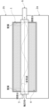
- FIG. 1 is a schematic diagram showing a powder rolling unit according to an embodiment of the present disclosure as viewed from the side.
- FIG. 2 is a schematic diagram showing a powder rolling unit according to an embodiment of the present disclosure as viewed from above.
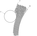
- FIG. 3A is a schematic diagram illustrating particles of powder material being uniformly delivered to a nip region by a squeegee according to an embodiment of the present disclosure.
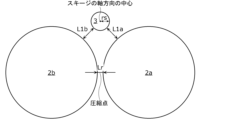
- FIG. 3B is a schematic diagram showing the positional relationship between a pair of rolling rolls and a squeegee when the powder rolling unit according to the embodiment of the present disclosure is viewed from the side.
- FIG. 1 is a schematic diagram showing a powder rolling unit according to an embodiment of the present disclosure as viewed from the side.
- FIG. 2 is a schematic diagram showing a powder rolling unit according to an embodiment of the present disclosure as viewed from above.
- FIG. 3A is a schematic diagram illustrating particles of powder material being uniformly delivered to a nip region by a sque
- FIG. 4 is a diagram showing the presence or absence of a squeegee, the presence or absence of vibration of the squeegee, the particle size (D50), the distance between the squeegee and the rolling roll, the distance between the squeegee and the rolling roll/particle size (D50), the presence or absence of missing material mixture, the presence or absence of a bridge in the hopper, and the variation in basis weight.
- each figure is a schematic diagram in which emphasis, omissions, or adjustments to the ratio have been made as appropriate to illustrate the present disclosure, and is not necessarily an exact illustration, and may differ from the actual shape, positional relationship, and ratio.
- the same reference numerals are used for substantially the same configuration, and duplicate explanations may be omitted or simplified.
- thickness direction or cylindrical shape does not only mean that it is completely thickness direction or cylindrical, but also means that it is substantially thickness direction or cylindrical, that is, it includes an error of about a few percent.
- thickness direction or cylindrical shape means thickness direction or cylindrical to the extent that the effects of this disclosure can be achieved. The same applies to other expressions using "direction" and "shape.”
- the powder rolling unit applies vibrations to the powder near the rolling rolls to improve the fluidity of the powder in the nip region, preventing clogging of the powder and enabling uniformity of the basis weight of the resulting rolled sheet.
- Such a powder rolling unit includes a hopper which is a material supply section, a pair of rolling rolls, and a squeegee.
- the squeegee vibrates with ultrasonic waves, and imparts fluidity to the powder by transmitting the vibrations to the powder.
- the hopper may have one or more squeegees.
- FIG. 1 is a schematic diagram showing a powder rolling unit according to an embodiment of the present disclosure as seen from the side. Shown in FIG. 1 are a hopper 1, rolling rolls 2a and 2b, a squeegee 3, powder material 4, and the resulting rolled sheet 5.
- FIG. 2 is a schematic diagram showing a powder rolling unit according to an embodiment of the present disclosure as viewed from above.
- the axial direction of the squeegee 3 is indicated by an arrow, and the standing wave caused by the vibration of the squeegee 3 is indicated by a two-dot chain line.
- FIG. 3A is a schematic diagram showing how particles of powder material 4 are uniformly delivered to a nip region by a squeegee 3 according to an embodiment of the present disclosure.
- FIG. 3B is a schematic diagram showing the positional relationship between a pair of rolling rolls 2a, 2b and a squeegee 3 when the powder rolling unit according to the embodiment of the present disclosure is viewed from the side.
- Figure 4 shows whether the squeegee 3 is present, whether the squeegee 3 vibrates, particle size (D50), the distances L1a and L1b between the squeegee 3 and the rolling rolls 2a and 2b, the distances L1a and L1b between the squeegee 3 and the rolling rolls 2a and 2b/particle size (D50), whether there is a mixture dropout, whether there is a bridge in the hopper 1, and the variation in basis weight.
- D50 particle size
- the powder rolling unit is equipped with a hopper 1 that stores a powder material 4 made of powder above a pair of rolling rolls 2a, 2b and has the function of supplying the powder material 4 to the pair of rolling rolls 2a, 2b, and a squeegee 3 arranged inside the hopper 1.
- the squeegee 3 is placed in the hopper 1 and is vibrated at a predetermined frequency by the vibrator 6.
- the squeegee 3 vibrated by the vibrator 6 can impart vibrations to the powder material 4 stored inside the hopper 1. This allows the squeegee 3 to constantly supply the powder material 4 to the rolling rolls 2a, 2b so as not to cause the powder material 4 to clog the pair of rolling rolls 2a, 2b.
- the pair of rolling rolls 2a, 2b may be simply referred to as rolling rolls 2a, 2b.
- the powder material 4 supplied to the rolling rolls 2a and 2b at a constant rate is rolled at the compression point where the distance between the surface of the rolling roll 2a and the surface of the rolling roll 2b is the shortest. Therefore, a rolled sheet 5 made of the powder material 4 rolled by the rolling rolls 2a and 2b at the compression point can be obtained.
- the squeegee 3 is disposed above the rolling rolls 2a, 2b, and is disposed so as to be parallel to the axial direction of each of the rolling rolls 2a, 2b. This is because if the squeegee 3 is not disposed parallel to the rolling rolls 2a, 2b, the distance from one end of the squeegee 3 to the compression point may differ from the distance from the other end of the squeegee 3 to the compression point. In this case, a difference will occur due to variation between the basis weight at one end of the obtained rolled sheet 5 and the basis weight at the other end of the rolled sheet 5.
- the squeegee 3 is positioned parallel to the rolling rolls 2a, 2b when viewed along the flow direction of the rolled sheet 5. This is because if it is not positioned parallel, the distance from the center of the squeegee 3 to the compression point will be different from the distance from the end of the squeegee 3 to the compression point, resulting in a difference due to variation in the basis weight of the center of the resulting rolled sheet 5 and the basis weight of the end of the rolled sheet 5.
- parallel does not only mean completely parallel, but also means substantially parallel, that is, with an error of about a few percent.
- the squeegee 3 also vibrates at a predetermined frequency. Specifically, the squeegee 3 vibrates at a frequency of 2 kHz to 300 kHz.
- the squeegee 3 can be vibrated efficiently by using a vibrator 6 that vibrates at a frequency of 2 kHz to 300 kHz.
- a vibrator 6 that vibrates at a frequency of 2 kHz to 300 kHz.
- a high-frequency vibration of 2 kHz to 300 kHz is required to impart fluidity to the powder. This is because low-frequency vibrations of less than 2 kHz do not vibrate the powder enough, making it impossible to impart sufficient fluidity.
- High-frequency vibrations of more than 300 kHz also cause large vibration attenuation when the vibrations are transmitted through the powder, making it impossible to impart sufficient fluidity to the powder.
- the squeegee 3 vibrating at the above frequency is in contact with the powder material 4, so when the squeegee 3 vibrates, the vibration of the squeegee 3 is transmitted to the powder material 4.
- the powder material 4 vibrates the frictional resistance between the powder particles (between particles) is reduced, improving the fluidity of the powder.
- the fluidity of the powder material 4 is improved by the vibration of the squeegee 3, making it possible to constantly supply the powder material 4 to the compression point.
- the powder material 4 on the rolling rolls 2a and 2b moves with the rotation direction of the rolling rolls 2a and 2b.
- the powder constituting the powder material 4 is not aligned and exists in a disorderly manner.
- the powder material 4, which is composed of powders that exist in a disorderly manner passes between the rolling rolls 2a and 2b and the squeegee 3 that is arranged with a certain gap between them and is vibrating, so that the powder constituting the powder material 4 can be aligned before reaching the compression point.
- aligning the powder constituting the powder material 4 the filling rate of the powder material 4 supplied to the compression point can be controlled, the loss of the mixture can be suppressed, and the variation in the basis weight of the obtained rolled sheet 5 can be reduced.
- the powder material 4 when the squeegee 3 does not vibrate, the powder material 4 is not subjected to vibration from the squeegee 3, so the powder is simply present in a disorderly manner, and it is not possible to align the powder. As a result, the fluidity of the powder material 4 is not improved, and blockage of the powder material 4 may occur when the powder material 4 passes through the squeegee 3. As a result, even if clogging of the powder material 4 does not occur, the filling rate of the powder material 4 cannot be controlled, making it difficult to reduce the variation in the basis weight of the resulting rolled sheet 5.
- the squeegee 3 only needs to vibrate in at least one of the thickness direction of the resulting rolled sheet 5, the width direction of the rolled sheet 5, and the flow direction of the rolled sheet 5.
- the squeegee 3 vibrates in two or more directions, it is possible to further improve the fluidity of the powder material 4.
- the squeegee 3 has the role of improving the fluidity of the powder material 4 in the nip region of the rolling rolls 2a and 2b, and is therefore preferably located as close as possible to the rolling rolls 2a and 2b.
- at least a part of the squeegee 3 may be located between the rolling rolls 2a and 2b so as not to come into contact with the rolling rolls 2a and 2b.
- at least a part of the squeegee 3 may be located in the nip region.
- it is preferable that the squeegee 3 is located above the rolling rolls 2a and 2b so as to overlap both of them.
- the nip region is the region between the rolling rolls 2a and 2b.
- the distance L1a between the rolling roll 2a and the squeegee 3 is the shortest distance when a straight line is drawn between the axial center of the rolling roll 2a and the axial center of the squeegee 3
- the distance L1b between the rolling roll 2b and the squeegee 3 is the shortest distance when a straight line is drawn between the axial center of the rolling roll 2b and the axial center of the squeegee 3
- the distance of the compression point where the distance between the rolling rolls 2a and 2b is the shortest (the distance between compressions), i.e., the shortest distance Lr between the rolling roll 2a and the rolling roll 2b at the compression point, are defined.
- At least one of the distances L1a and L1b is greater than or equal to the distance Lr and less than or equal to Lr + 50 mm. This is because, if at least one of the distances L1a and L1b is greater than Lr + 50 mm, it becomes difficult for the powder aligned by vibration to maintain that alignment up to the nip region, resulting in variation in the basis weight of the resulting rolled sheet 5. Also, if at least one of the distances L1a and L1b is smaller than Lr, the amount of powder material 4 supplied to the nip region becomes small, making it impossible to obtain the desired rolled sheet 5. Note that the distances L1a and L1b do not necessarily have to be the same distance.
- the squeegee 3 is located in a range where either Lr ⁇ L1a ⁇ Lr+50 mm or Lr ⁇ L1a ⁇ Lr+50 mm is satisfied with respect to the rolling roll 2a. Also, it is sufficient that the squeegee 3 is located in a range where either Lr ⁇ L1b ⁇ Lr+50 mm or Lr ⁇ L1b ⁇ Lr+50 mm is satisfied with respect to the rolling roll 2b.
- the position of the squeegee 3 in the thickness direction of the obtained rolled sheet 5, i.e., the distance between the center of the squeegee 3 and the center between the rolling rolls 2a and 2b, i.e., the distance between the center of the squeegee 3 and the compression point, is less than or equal to Lr/2 + radius rs of the squeegee 3.
- the squeegee 3 is located above the rolling rolls 2a and 2b so as to overlap both of them. If this range is exceeded, the distance L1a or distance L1b will be large, and powder material 4 with poor powder alignment will be supplied to the nip region, causing variations in the basis weight of the rolled sheet 5.
- the shortest distance Lr between the rolling rolls 2a and 2b is set according to the powder particle diameter (D50).
- the squeegee 3 is formed, for example, from a metal material.
- a metal material for the squeegee 3 high frequencies propagate through the squeegee 3 without significant attenuation. High frequencies with short wavelengths tend to attenuate easily, but metal materials have the property of easily transmitting waves, so a squeegee 3 made of a metal material can suppress the attenuation of high frequencies. As a result, the vibration state is uniform throughout the squeegee 3, suppressing variation in the basis weight in the width direction of the rolled sheet 5.
- metal materials examples include stainless steel, titanium, aluminum, copper, iron, and nickel.
- stainless steel or titanium is preferred as a metal material because it is highly corrosion-resistant and does not rust easily.
- Titanium is also more preferred as a metal material because it is light and easily vibrates with ultrasonic waves.
- the squeegee 3 may be made of a material other than a metal material.
- the squeegee 3 may be made of a resin material or a ceramic material, or may be made of a composite member that selectively uses two or more materials from among a metal material, a resin material, and a ceramic material.
- the shape of the squeegee 3 is cylindrical in order to apply uniform vibrations to the surrounding powder material 4.
- the shape of the squeegee 3 is a long cylinder extending along a predetermined direction.
- the diameter of the squeegee 3 is 2 mm or more and 30 mm or less. This is because if the diameter of the squeegee 3 is greater than 30 mm, the squeegee 3 will be difficult to vibrate, making it difficult to impart sufficient fluidity to the powder material 4.
- the diameter is less than 2 mm, the squeegee 3 will become too thin and will deform, making it difficult to impart sufficient fluidity to the powder material 4.
- the amplitude direction of the squeegee 3 it is desirable that it vibrates in at least one of the width direction of the resulting rolled sheet 5, the thickness direction of the rolled sheet 5, and the length direction of the rolled sheet 5. If the squeegee 3 vibrates in two or more of the above three directions, it is possible to further improve the fluidity of the powder material 4. In particular, in the case of a cylindrical squeegee 3, it is desirable that it vibrates in at least one of the thickness direction or flow direction of the rolled sheet 5 in order to efficiently transmit vibrations to the powder material 4 surrounding the squeegee 3. In this case, it is possible to further improve the fluidity of the powder material 4.
- the amplitude of the squeegee 3 is 0.1 ⁇ m or more in at least one of the three directions mentioned above. This is because if it is less than 0.1 ⁇ m, it becomes difficult to impart sufficient fluidity to the powder material 4. From the viewpoint of improving the fluidity of the powder material 4, it is desirable that the amplitude of the squeegee 3 is as large as possible, so the amplitude of the squeegee 3 may be amplified to a practically feasible extent.
- the squeegee 3 usually vibrates due to a standing wave. In other words, when the squeegee 3 vibrates, there are vibration antinodes where the amplitude is large and vibration nodes where the amplitude is small.
- the squeegee 3 is vibrated by a vibrator 6 connected to the squeegee 3.
- the squeegee 3 is vibrated at its natural frequency of 2 kHz to 300 kHz by the vibrator 6. That is, the squeegee 3 vibrates at a high frequency close to the ultrasonic band.
- the vibration of the squeegee 3 is transmitted to the powder material 4, thereby increasing the fluidity of the powder material 4.
- clogging is suppressed when the powder material 4 passes through the gap between the rolling rolls 2a, 2b and the squeegee 3.
- the vibration of the squeegee 3 reduces the friction between adjacent powder particles and increases the fluidity, thereby suppressing aggregation of the powder material 4.
- the fluidity of the powder material 4 tends to increase as the vibration frequency of the squeegee 3 increases. Therefore, if the squeegee 3 is vibrated at a frequency of 2 kHz or more, which is in the high frequency range near the ultrasonic band, the fluidity of the powder material 4 can be sufficiently increased. However, the higher the frequency, the more the vibration tends to attenuate, making it more difficult for the vibration of the squeegee 3 to be transmitted through the powder material 4. However, if the frequency is 300 kHz or less, the fluidity of the powder material 4 can be sufficiently increased.
- the vibrating squeegee 3 allows the powder material 4 to pass through the gap between the rolling rolls 2a, 2b and the squeegee 3 without stagnation or agglomeration. This allows the film thickness and filling rate of the powder material 4 to be adjusted. As a result, a rolled sheet 5 with little variation in basis weight can be obtained.
- the squeegee 3 is equipped with a vibrator 6. When the vibrator 6 vibrates, the vibrations are transmitted to the squeegee 3, causing the squeegee 3 to vibrate.
- the vibrator 6 has multiple piezoelectric bodies and electrodes provided on the end faces of each of the multiple piezoelectric bodies.
- each of the multiple piezoelectric bodies is sandwiched between electrodes.
- the vibrator 6 has a sandwich structure of piezoelectric bodies and electrodes.
- the number of piezoelectric bodies is an even number, such as two, four, or six.
- the electrodes are thin metal plates made of, for example, copper, phosphor bronze, or the like.
- the piezoelectric body may be, for example, a piezoelectric ceramic such as lead zirconate titanate ( PbTiO3 - PbZrO3 , commonly known as PZT) or barium titanate ( BaTiO3 ).
- the piezoelectric body may be, for example, a piezoelectric single crystal such as quartz or LiNbO3 .
- each piezoelectric body has a thickness of approximately 2 mm to 5 mm.
- the transducer 6 has a sandwich structure in which a piezoelectric body is sandwiched between a metal front plate and a metal backing plate, and a Langevin type transducer with an overall length of half the wavelength is preferred for its high output and high reliability.
- the Langevin type transducer has a structure in which a metal front plate and a metal backing plate are arranged on either side of a piezoelectric body such as PZT, and are fastened with bolts.
- the metal front plate and the metal backing plate are made of duralumin.
- the bolts are made of steel or titanium alloy.
- a screw hole for connection is formed in the center of the metal front plate, and the squeegee 3 is inserted into the screw hole and fastened, connecting the transducer 6 and the squeegee 3 in a tight contact manner. This allows the vibration generated by the transducer 6 to be transmitted to the squeegee 3.
- a horn that amplifies the amplitude may be connected between the transducer 6 and the squeegee 3, or a horn that disperses the direction of the vibration may be connected.
- the vibrator 6 is a vibrator that excites waves. A positive charge and a negative charge are applied to the thin metal plates attached to both end faces of the piezoelectric body of the vibrator 6. This converts electrical energy into mechanical energy. The vibrator 6 vibrates at a high frequency as the electrical signal is converted into mechanical vibration. This vibration is propagated to the squeegee 3.
- the polarization direction of the piezoelectric material such as PZT coincides with the longitudinal direction of each of the vibrators 6 so that the vibrators 6 have a structure in which they expand and contract in their respective longitudinal directions.
- the vibration direction of the vibrator 6 is the longitudinal direction of the vibrator 6, making it easier to control the vibration direction of the generated vibrations.
- the rolling rolls 2a and 2b roll the powder material 4 supplied from the hopper 1 to form the rolled sheet 5.
- the powder material 4 whose fluidity has been improved by the vibration of the squeegee 3, is supplied to the nip area of the rolling rolls 2a and 2b, where it is compressed and stretched.
- the shortest distance between the rolling rolls 2a and 2b which is the compression point, becomes the thickness of the rolled sheet 5.
- the distance between the rolling rolls 2a and 2b is determined by the thickness of the rolled sheet 5, but it is desirable that the shortest distance Lr between the rolling rolls 2a and 2b is 2 mm or less.
- the obtained rolled sheet 5 may be passed through the gap between the rolling rolls 2a and 2b multiple times.
- the rolled sheet 5 may be stretched one or more times by using rolls having different roll diameters, peripheral speeds, gaps, etc. from the rolling rolls 2a and 2b.
- the rolling rolls 2a and 2b have a predetermined diameter, for example, 100 mm or more and 200 mm or less.
- the rolling rolls 2a and 2b may be heated to heat-press the powder material 4 with the rolling rolls 2a and 2b, or the rolled sheet 5 may be heat-pressed with the rolling rolls 2a and 2b.
- the surface roughness (surface roughness) of one of the rolling rolls 2a and 2b, the rolling roll 2a is higher than the surface roughness of the other of the rolling rolls 2a and 2b, the rolling roll 2b.
- the surface roughness of the rolling roll 2a is higher than the surface roughness of the rolling roll 2b.
- the rolled sheet 5 obtained by supplying the powder material 4 to the nip region and pressing and stretching it is more likely to be discharged from between the rolling rolls 2a and 2b while adhering to the surface of the rolling roll 2a. This makes it possible for the rolling rolls 2a and 2b to transport the rolled sheet 5 that has passed between the rolling rolls 2a and 2b to the next roll.
- the surface roughness A1 of the rolling roll 2a is 0.5 ⁇ m
- the surface roughness B1 of the rolling roll 2b is 0.2 ⁇ m.
- the surface roughness A1 of the rolling roll 2a is 2.5 times the surface roughness B1 of the rolling roll 2b.
- the rolling sheet 5 having a weak strength may be torn off from the rolling roll 2a. In this case, the rolling sheet 5 that has passed between the rolling rolls 2a and 2b cannot be discharged toward the next roll arranged at the desired position.
- the surface roughness A1 is higher than the surface roughness B1 so that the rolling sheet 5 can be carried to the next roll while being stuck to the rolling roll 2a.
- the surface roughness A1 and the surface roughness B1 may be appropriately set according to the particle diameter of the powder, the material used for the surfaces of the rolling rolls 2a and 2b, the rotation speed of the rolling rolls 2a and 2b, etc. Therefore, surface roughness A1/surface roughness B1 is not limited to being 2.5.
- the rotation speed of one of the rolling rolls 2a and 2b, the rolling roll 2a is faster than the rotation speed of the other of the rolling rolls 2a and 2b. Since the rolling roll 2a has a higher surface roughness than the rolling roll 2b, the rolling roll 2a is set to rotate faster than the rolling roll 2b so that the rolling roll 2a can easily take up the rolled sheet 5.
- the rolling rolls 2a and 2b can transport the rolled sheet 5 that has passed between the rolling rolls 2a and 2b to the next roll.
- the rotation speed A2 of the rolling roll 2a is 26 m/min
- the rotation speed B2 of the rolling roll 2b is 6.5 m/min
- the rotation speed A2 of the rolling roll 2a is four times the rotation speed B2 of the rolling roll 2b.
- the rotation speeds A2 and B2 may be set appropriately depending on the particle size of the powder, the material used for the surfaces of the rolling rolls 2a and 2b, the surface roughnesses A1 and B1, etc. Therefore, the ratio of the rotation speed A2/the rotation speed B2 is not limited to being 4.
- the surface roughness A1 of the rolling roll 2a is set to 0.5 ⁇ m
- the surface roughness B1 of the rolling roll 2b is set to 0.2 ⁇ m
- the rotation speed A2 of the rolling roll 2a is set to 26 m/min
- the rotation speed B2 of the rolling roll 2b is set to 6.5 m/min
- the ratio of the rotation speed A2 of the rolling roll 2a to the peripheral speed ratio of the rotation speed B2 of the rolling roll 2a is set to 4
- the shortest distance Lr between the rolling rolls 2a and 2b is set to 455 ⁇ m
- the width of the hopper 1 is set to 240 mm
- the diameter of the squeegee 3 is set to 4 mm.
- the following are shown: presence or absence of squeegee 3, presence or absence of vibration of squeegee 3 due to ultrasonic waves, particle diameter (D50), distance L1a, L1b, distance L1a, L1b/particle diameter (D50), presence or absence of missing mixture, presence or absence of bridges in hopper 1, and variation in basis weight.
- the variation in basis weight is calculated as the average of the values obtained by subtracting the minimum value from the maximum value and dividing the value by 2.
- the squeegee 3 vibrates at a frequency of 2 kHz to 300 kHz, a powder material 4 with a powder particle diameter of 952 ⁇ m is used, and the distances L1a, L1b are 20,000 ⁇ m, so the distance L1a, L1b/particle diameter (D50) is 21, and a bridge is formed in the hopper 1, so the rolled sheet 5 is not output from between the rolling rolls 2a and 2b.
- the squeegee 3 vibrates at a frequency of 2 kHz to 300 kHz, a powder material 4 with a powder particle diameter of 511 ⁇ m is used, and the distances L1a, L1b are 10,000 ⁇ m, the distance L1a, L1b/particle diameter (D50) is 20, and a bridge is formed in the hopper 1, so that no rolled sheet is output from between the rolling rolls 2a and 2b.
- the squeegee 3 vibrates at a frequency of 2 kHz to 300 kHz, a powder material 4 with a powder particle diameter of 511 ⁇ m is used, and when the distances L1a and L1b are 20,000 ⁇ m, the distance L1a and L1b/particle diameter (D50) is 39, the occurrence of mixture loss is suppressed, the occurrence of bridges in the hopper 1 is suppressed, and the variation in basis weight is ⁇ 0.79%.
- the squeegee 3 vibrates at a frequency of 2 kHz to 300 kHz, a powder material 4 with a powder particle diameter of 511 ⁇ m is used, and when the distances L1a and L1b are 25,000 ⁇ m, the distance L1a and L1b/particle diameter (D50) is 49, the occurrence of mixture loss is suppressed, the occurrence of bridges in the hopper 1 is suppressed, and the variation in basis weight is ⁇ 2.51%.
- the squeegee 3 vibrates at a frequency of 2 kHz to 300 kHz, a powder material 4 with a powder particle diameter of 511 ⁇ m is used, and when the distances L1a, L1b are 30,000 ⁇ m, the distance L1a, L1b/particle diameter (D50) is 59, the occurrence of mixture loss is suppressed, the occurrence of bridges in the hopper 1 is suppressed, and the variation in basis weight is ⁇ 3.4%.
- the squeegee 3 vibrates at a frequency of 2 kHz to 300 kHz, a powder material 4 with a powder particle diameter of 308 ⁇ m is used, and when the distances L1a and L1b are 20,000 ⁇ m, the distance L1a and L1b/particle diameter (D50) is 65, which causes the mixture to come off and suppresses the occurrence of bridges in the hopper 1.
- the squeegee 3 vibrates at a frequency of 2 kHz to 300 kHz, a powder material 4 with a powder particle diameter of 225 ⁇ m is used, and when the distances L1a and L1b are 20,000 ⁇ m, the distance L1a and L1b/particle diameter (D50) is 89, which causes the mixture to come off and suppresses the occurrence of bridges in the hopper 1.
- the lower limit of the distance L1a, L1b/particle diameter (D50) was set to 22.
- the upper limit of distance L1a, L1b/particle diameter (D50) was set to 58.
- the powder material 4 is supplied to a hopper 1.
- the hopper 1 temporarily stores the powder material 4 and continuously supplies the powder material 4 to the nip region of the rolling rolls 2a and 2b.
- the method of supplying the powder material 4 to the hopper 1 may be to supply the powder material 4 intermittently to the nip region of the rolling rolls 2a and 2b, or to supply the powder material 4 continuously to the nip region of the rolling rolls 2a and 2b using a known constant-volume supply device such as a screw feeder or a vibration feeder.
- the particle diameter (D50) of the powder in the powder material 4 is preferably, for example, 100 ⁇ m or more and 700 ⁇ m or less.
- the smaller the particle diameter (D50) of the powder the more likely it is that the fluidity of the powder material 4 will decrease, but the vibration of the squeegee 3 improves the fluidity of the powder material 4.
- retention and aggregation are suppressed in the powder material 4, and the powder is aligned and arranged.
- the powder material 4 is in a high-quality state with little variation in basis weight.
- the particle diameter (D50) is the volume-based median diameter calculated from the particle size distribution measured by a laser diffraction/scattering method or the like. This particle diameter (D50) can be measured using a commercially available laser analysis/scattering type particle size distribution measuring device.
- the basis weight is a value expressed by weight of the powder per unit area, and the unit of the basis weight is expressed in g/cm 2 , for example.
- the powder may contain only one type of powder, or may contain two or more types of powder.
- Powder material 4 may be a granulated powder made by compacting a predetermined amount of powder into larger particles. Powder material 4 may be any powdery substance. In other words, the raw material of powder material 4, the composition of powder material 4, and the particle shape of powder material 4 are not particularly limited. In this embodiment, powder material 4 is a particle group containing a positive electrode active material used in lithium ion secondary batteries.
- the manufacturing method includes supplying powder material 4 to a hopper 1 (powder supplying step), supplying powder material 4 with aligned powder to a nip region by passing the powder material 4 between rolling rolls 2a, 2b and a squeegee 3 (powder alignment step), and rolling the powder material 4 by the rolling rolls 2a, 2b to obtain a rolled sheet 5 (powder rolling step).
- the powder material 4 is prepared.
- the raw material of the powder material 4 is not particularly limited, but for example, a particle group containing an active material may be used.
- the active material is mixed with appropriate additives (for example, a binder, a conductive material, etc.) to prepare the powder material 4.
- appropriate additives for example, a binder, a conductive material, etc.
- the mixing method include a method of mixing using a mortar, a ball mill, a mixer, etc. In particular, a method of mixing the powder without using a solvent, etc. is preferable because it does not cause material deterioration.
- the powder material 4 is supplied to the hopper 1.
- the powder material 4 may be supplied to the hopper 1 intermittently, or may be supplied continuously using a known constant-amount supply device such as a screw feeder or a vibrating feeder.
- the squeegee 3 is used to supply the powder material 4 with aligned powder to the nip region. That is, in the powder alignment process, the squeegee 3 controls the amount of powder material 4 supplied to the nip region and the degree of disintegration. At this time, the squeegee 3 vibrates at a frequency of 2 kHz to 300 kHz. The squeegee 3 resonates (natural vibration) with a sine standing wave. The squeegee 3 vibrates in at least one of the thickness direction, width direction, and length direction of the resulting rolled sheet 5. This makes it possible to increase the fluidity of the powder material 4. Furthermore, when the squeegee 3 vibrates in multiple directions, the fluidity of the powder material 4 can be further increased.
- the powder rolling process involves roll pressing using rolling rolls 2a and 2b.
- the powder material 4, whose powder has been aligned by the vibration of the squeegee 3, is compressed from the nip region with the supply amount controlled by the vibration of the squeegee 3.
- the powder supplying process, the powder alignment process, and the powder rolling process are carried out in this order to form the rolled sheet 5 made of the powder material 4.
- a rolled sheet 5 can be used in an energy device.
- an electrode sheet for an energy device can be manufactured.
- the energy device thus produced can have an electrode sheet with little variation in basis weight, in which the powder material 4 is given fluidity and directly applied. Therefore, according to the manufacturing method of the rolled sheet 5, the powder material 4 is directly applied without dispersing it in a solvent or the like, applying it, and drying it. This makes it possible to suppress deterioration of the material caused by the solvent, and to realize a high capacity energy device. In addition, it is possible to suppress the increase in costs caused by using a solvent and drying the solvent. Furthermore, it is possible to suppress the large amount of energy consumption in the drying process, resulting in a manufacturing method with a small environmental impact. On the other hand, if the basis weight of the rolled sheet 5 is highly uniform, it is possible to improve the quality of the electrode in the energy device, and it is possible to manufacture a high-capacity energy device with good quality at low cost.
- the rolled sheet 5 according to this embodiment is used, for example, in energy devices.
- the formed rolled sheet 5 has a film thickness of 30 ⁇ m or more.
- the rolled sheet 5 also contains powder composed of at least one type of particulate material.
- the concentration of the solvent contained in the powder layer is 50 ppm or less.
- the variation in basis weight in the powder layer is small.
- the rolled sheet 5 of this embodiment can be used, for example, in a lithium ion secondary battery.
- the following provides details on using the rolled sheet 5 in a lithium-ion secondary battery.
- the rolled sheet 5 is used, for example, in combination with a known current collector as an electrode (positive or negative electrode) of a lithium-ion secondary battery.
- a known current collector as an electrode (positive or negative electrode) of a lithium-ion secondary battery.
- Such an electrode has a current collector and the rolled sheet 5.
- the electrode may further include another layer located between the current collector and the rolled sheet 5.
- the other layer may be, for example, a connection layer made of a conductive carbon material.
- the thickness of the rolled sheet 5 is 30 ⁇ m or more. There is no particular upper limit to the thickness of the rolled sheet 5, but the thickness of the rolled sheet 5 is, for example, 2000 ⁇ m or less.
- the rolled sheet 5 also contains a powder material 4 that is composed of at least one type of particulate material.
- the concentration of the solvent contained in the rolled sheet 5 is 50 ppm or less.
- the powder layer is substantially free of solvent.
- substantially free of solvent means that the solvent is not contained at all, and that the solvent is inevitably contained at 50 ppm or less as an impurity, etc.
- the solvent concentration is based on weight. In any region on the surface of the rolled sheet 5, the variation in the basis weight of the powder layer is, for example, 8% or less.
- the basis weight can be measured, for example, by the following method.
- the rolled sheet 5 is punched out into circles or polygons of the desired size, and the weight of the punched out rolled sheet 5 is measured.
- the basis weight can be calculated by dividing this weight by the area of the punched circle or polygon.
- the variation in basis weight can be measured, for example, by the following method.
- an arbitrary area on the surface of the powder layer in plan view is selected.
- This area may be the central area on the surface of the powder layer, or may be an area including the edge of the powder layer.
- five or more circular or polygonal shapes of arbitrary size are punched out, and the basis weight is measured using the above-mentioned method.
- Nine or more points may be punched out in order to increase the accuracy of the measurement of variation.
- the basis weight variation is calculated by dividing the difference (more specifically, the absolute value of the difference) between the average basis weight of all punched out points and the basis weight of the point among the punched out points that differs most from the average by the average.
- a basis weight variation of 8% or less means that the difference between the basis weight and the average at any punched out point is 8% or less of the average.
- the rolled sheet 5 is produced, for example, through a coating process that is substantially free of solvent. Therefore, it is possible to form a rolled sheet 5 that is substantially free of solvent. As a result, the rolled sheet 5 is not damaged by the solvent. Therefore, deterioration of the rolled sheet 5 is suppressed, and the variation in the basis weight of the powder material 4 in the rolled sheet 5 is small, making it possible to form a powder layer for a large, high-capacity energy device that has high capacity and excellent quality.
- the rolled sheet 5 can also be used, for example, as the positive or negative electrodes of energy devices such as lithium ion secondary batteries.
- the rolled sheet 5 is used for a positive electrode
- the rolled sheet 5 containing the powder material 4 is a positive electrode mixture layer.
- the positive electrode mixture layer is used in combination with a positive electrode current collector.
- the powder material 4 in the positive electrode mixture layer contains a positive electrode active material as at least one type of particle material.
- the rolled sheet 5 is used for a negative electrode
- the rolled sheet 5 containing the powder material 4 is a negative electrode mixture layer.
- the negative electrode mixture layer is used in combination with a negative electrode current collector.
- the powder material 4 in the negative electrode mixture layer contains a negative electrode active material as at least one type of particle material.
- the concentration of the solvent contained in the positive electrode mixture layer and the negative electrode mixture layer is 50 ppm or less.
- the positive electrode mixture layer and the negative electrode mixture layer are substantially free of solvent.
- substantially free of solvent means that these layers are completely free of solvent, and that these layers unavoidably contain 50 ppm or less of solvent as impurities, etc.
- the solvent is, for example, an organic solvent.
- the method for measuring the solvent is not particularly limited, and can be measured using, for example, gas chromatography, mass change method, etc.
- organic solvents include non-polar organic solvents such as heptane, xylene, and toluene, polar organic solvents such as tertiary amine solvents, ether solvents, thiol solvents, and ester solvents, and combinations thereof.
- tertiary amine solvents include triethylamine, tributylamine, and triamylamine.
- ether solvents include tetrahydrofuran and cyclopentyl methyl ether.
- thiol solvents include ethane mercaptan.
- ester solvents include butyl butyrate, ethyl acetate, and butyl acetate.
- the positive electrode active material is a material in which metal ions such as lithium (Li) are inserted or removed from the crystal structure at a higher potential than the negative electrode, and oxidation or reduction occurs as the metal ions such as lithium are inserted or removed.
- the type of positive electrode active material is appropriately selected, and examples include oxide active materials.
- the positive electrode active material in the present embodiment may be, for example, lithium transition metal oxide particles containing a transition metal element such as Co, Mn, or Ni.
- the lithium transition metal oxide particles include LixCoO2 , LixNiO2 , LixMnO2 , LixCoyNi1 - yO2 , LixCoyM1- yOz , LixNi1 - yMyOz , LixMn2O4 , LixMn2- yMyO4, LiMPO4 , and Li2MPO4F (M: at least one of Na , Mg , Sc , Y , Mn , Fe, Co , Ni, Cu, Zn , Al , Cr , Pb, Sb, and B; 0 ⁇ x ⁇ 1.2, 0 ⁇ y ⁇ 0.9, and 2.0 ⁇ z ⁇ 2.3).
- the positive electrode active material particles contain lithium nickel composite oxide particles such as Li x NiO 2 , Li x Co y Ni 1-y O 2 , or Li x Ni 1-y M y O z (M; at least one of Na, Mg, Sc, Y, Mn, Fe, Co, Ni, Cu, Zn, Al, Cr, Pb, Sb, and B, 0 ⁇ x ⁇ 1.2, 0 ⁇ y ⁇ 0.9, 2.0 ⁇ z ⁇ 2.3).
- lithium nickel composite oxide particles such as Li x NiO 2 , Li x Co y Ni 1-y O 2 , or Li x Ni 1-y M y O z (M; at least one of Na, Mg, Sc, Y, Mn, Fe, Co, Ni, Cu, Zn, Al, Cr, Pb, Sb, and B, 0 ⁇ x ⁇ 1.2, 0 ⁇ y ⁇ 0.9, 2.0 ⁇ z ⁇ 2.3).
- the shape of the positive electrode active material may be, for example, particulate.
- the particle diameter of the positive electrode active material is, for example, in the range of 0.05 ⁇ m to 30 ⁇ m, and may be in the range of 1 ⁇ m to 15 ⁇ m. If the particle diameter of the positive electrode active material is 0.05 ⁇ m or more, it is easy to handle. On the other hand, if the particle diameter is 30 ⁇ m or less, a small particle size active material is used, which increases the surface area and makes it easier to obtain a high-capacity positive electrode.
- the particle diameter of the material contained in the positive electrode mixture layer or the negative electrode mixture layer in this specification is, for example, the above-mentioned D50.
- a negative electrode active material is a material in which metal ions such as lithium are inserted or removed from the crystal structure at a lower potential than the positive electrode, and oxidation or reduction occurs as the metal ions such as lithium are inserted or removed.
- Examples of the negative electrode active material in this embodiment include lithium alloys such as metallic lithium, lithium-aluminum alloys, lithium-lead alloys, lithium-silicon alloys, and lithium-tin alloys, carbon materials such as graphite, coke, and organic sintered bodies, and metal oxides such as SnO 2 , SnO, and TiO 2. These may be used alone or in combination of two or more. In addition, as the negative electrode active material, a composite in which the above-mentioned negative electrode active materials are appropriately mixed may also be used.
- the particle diameter of the negative electrode active material is, for example, 30 ⁇ m or less. By using an active material with a small particle size, the surface area is increased, resulting in a high capacity.
- the positive electrode in this embodiment includes a positive electrode current collector made of, for example, a metal foil.
- the positive electrode current collector may be, for example, a foil, plate, mesh, or the like made of aluminum, gold, platinum, zinc, copper, stainless steel (SUS), nickel, tin, titanium, or an alloy of two or more of these metals.
- the thickness and shape of the positive electrode current collector may be appropriately selected depending on the application of the positive electrode.
- the negative electrode in this embodiment includes a negative electrode current collector made of, for example, a metal foil.
- the negative electrode current collector may be, for example, a foil, plate, mesh, or the like made of stainless steel, gold, platinum, zinc, copper, nickel, titanium, tin, or an alloy of two or more of these metals.
- the thickness and shape of the negative electrode current collector may be appropriately selected depending on the application of the negative electrode.
- the powder rolling unit of the technique 1 in this embodiment includes the rolling rolls 2a and/or 2b for rolling the powder material 4 to form the rolled sheet 5, the hopper 1 for storing the powder material 4 above the rolling rolls 2a and/or 2b, and the squeegee 3 arranged above the rolling rolls 2a and 2b, arranged parallel to the axial directions of the rolling rolls 2a and 2b, and vibrating at a predetermined frequency.
- the squeegee 3 can impart vibrations to the powder material 4 stored inside the hopper 1.
- This allows the powder material 4 to be supplied constantly to the rolling rolls 2a and/or 2b (uniform powder supply amount) so that the powder material 4 is not blocked by the rolling rolls 2a and/or 2b. This improves the fluidity of the powder material 4 near the nip region inside the hopper 1.
- clogging of the powder material 4 in the nip region can be suppressed, and the variation in the basis weight of the rolled sheet 5 can be suppressed.
- a rolled sheet 5 with a uniform basis weight can be obtained.
- the powder rolling unit of Technology 2 in this embodiment is the powder rolling unit described in Technology 1.
- a pair of rolling rolls 2a, 2b is provided.
- the pair of rolling rolls 2a, 2b roll the powder material 4 to form a rolled sheet 5.
- the squeegee 3 is positioned parallel to the rolling rolls 2a, 2b, so the distance from one end of the squeegee 3 to the compression point is similar to the distance from the other end of the squeegee 3 to the compression point, making it less likely that differences due to variations will occur between the basis weight at one end of the resulting rolled sheet 5 and the basis weight at the other end of the rolled sheet 5.
- the powder rolling unit of Technology 3 in this embodiment is the powder rolling unit described in Technology 2.
- the surface roughness of one of the pair of rolling rolls 2a, 2b, the rolling roll 2a is higher than the surface roughness of the other of the pair of rolling rolls 2a, 2b, the rolling roll 2b.
- the powder rolling unit of Technology 4 in this embodiment is the powder rolling unit described in any one of Technology 1 to 3.
- the rotation speed of one rolling roll 2a is faster than the rotation speed of the other rolling roll 2b.
- the rolled sheet 5 is more easily discharged from between the rolls 2a and 2b while adhering to the surface of the roll 2a. This allows the rolls 2a and 2b to more easily transport the rolled sheet 5 that has passed between the rolls 2a and 2b to the next roll.
- the powder rolling unit of Technology 5 in this embodiment is the powder rolling unit described in any one of Technology 2 to 4.
- at least a portion of the squeegee 3 is disposed between the pair of rolling rolls 2a, 2b so as not to come into contact with the pair of rolling rolls 2a, 2b.
- the squeegee 3 can impart vibrations to the powder material 4.
- the vibration of the squeegee 3 improves the fluidity of the powder material 4, making it possible to obtain a rolled sheet 5 with little variation in basis weight.
- the powder rolling unit of Technology 6 in this embodiment is the powder rolling unit described in any one of Technologies 1 to 5.
- the predetermined frequency at which the squeegee 3 vibrates is 2 kHz or more and 300 kHz or less.
- the number of vibrations applied to the powder may be insufficient, making it impossible to impart sufficient fluidity to the powder.
- vibration attenuation increases as the vibrations are transmitted through the powder, making it impossible to impart sufficient fluidity to the powder.
- the powder rolling unit according to this embodiment is not limited to one squeegee 3. That is, the powder rolling unit may further include a multi-stage squeegee.
- the multi-stage squeegee may be arranged in the hopper 1 so that the axial direction of the multi-stage squeegee is parallel to the axial direction of the rolling rolls 2a and 2b.
- the multi-stage squeegee can gently break down the powder material 4 in advance so that the powder material 4 does not become blocked between the rolling rolls 2a and 2b and the squeegee 3.
- multiple multi-stage squeegees may be arranged above the squeegee 3.
- a multi-stage squeegee may be arranged above the squeegee 3 and the rolling roll 2a, and another multi-stage squeegee may be arranged above the squeegee 3 and the rolling roll 2b.
- the powder rolling unit disclosed herein can form a uniform powder layer without using a solvent, making it suitable for applications such as the composite layer of high-quality lithium-ion secondary batteries.
Landscapes
- Engineering & Computer Science (AREA)
- Manufacturing & Machinery (AREA)
- Mechanical Engineering (AREA)
- Chemical & Material Sciences (AREA)
- Materials Engineering (AREA)
- Chemical Kinetics & Catalysis (AREA)
- Electrochemistry (AREA)
- General Chemical & Material Sciences (AREA)
- Powder Metallurgy (AREA)
Abstract
粉体圧延ユニットは、粉体材料(4)を圧延することにより圧延シート(5)を成形する圧延ロール(2a)および/または(2b)と、圧延ロール(2a)および/または(2b)の上方部に粉体材料(4)を貯蔵するホッパー(1)と、圧延ロール(2a、2b)の上方部に配置され、かつ、圧延ロール(2a、2b)におけるそれぞれの軸方向と平行となるように配置され、所定の周波数で振動するスキージ(3)とを備える。そして、スキージ(3)と圧延ロール(2a、2b)との間の距離を、圧延される粉体材料(4)を構成する粉体の粒子径(D50)で除算した場合、22≦(スキージ(3)と圧延ロール(2a、2b))との間の距離(L1a、L1b)/粒子径(D50)≦58が成立する。
Description
本開示は、粉体圧延ユニットに関する。
近年では、粉体を直接成膜する乾式成膜方法は、溶媒中に粉体を分散させて塗工する湿式成膜法に比べ、高性能かつ環境負荷が小さい粉体層を形成できる工法として注目されている。乾式成膜方法によれば、溶媒による粉体への材料ダメージが抑制され、高性能を維持でき、溶媒を乾燥する必要がなく、消費エネルギー量を大幅に削減可能な粉体層を得ることができる。
従来の粉体の乾式成膜方法では、例えば、電極活物質を含む粉体から電極シート等の圧延シートを製造するために粉体圧延装置を用いた粉体の圧延成形が行われている。
例えば特許文献1には、粉体を圧延することにより圧延シートを成形する圧延部と、圧延部の上方に形成され粉体を貯槽するホッパーと、圧延シートの幅方向に複数設けられ、ホッパーに粉体を供給するフィーダーと、幅方向の膜厚が一定の範囲となるようにホッパー内の幅方向の粉体のレベルを制御する制御部とを備える粉体圧延装置が開示されている。
しかしながら、特許文献1では、粉体は成り行きで圧延部のニップ領域に流れるため、粉体の流れ方向の目付量が安定せず、圧延部を経て得られた圧延シートの目付量にばらつきが生じてしまう。
そこで本開示は、ニップ領域における粉体材料の閉塞を抑制し、圧延シートの目付量ばらつきを抑制することができる粉体圧延ユニットを提供することを目的とする。
本開示の一態様に係る粉体圧延ユニットは、粉体材料を圧延することにより圧延シートを成形する圧延ロールと、前記圧延ロールの上方部に前記粉体材料を貯蔵するホッパーと、前記圧延ロールの上方部に配置され、かつ、前記圧延ロールにおけるそれぞれの軸方向と平行となるように配置され、所定の周波数で振動するスキージとを備え、前記スキージと前記圧延ロールとの間の距離を、圧延される前記粉体材料を構成する粉体の粒子径(D50)で除算した場合、
22≦(前記スキージと前記圧延ロールとの間の距離)/前記粒子径(D50)≦58
が成立する。
22≦(前記スキージと前記圧延ロールとの間の距離)/前記粒子径(D50)≦58
が成立する。
本開示の粉体圧延ユニットによれば、ニップ領域における粉体材料の閉塞を抑制し、圧延シートの目付量ばらつきを抑制することができる。
なお、以下で説明する実施の形態は、いずれも包括的または具体的な例を示すものである。以下の実施の形態で示される数値、形状、材料、構成要素、構成要素の配置位置および接続形態等は、一例であり、本開示を限定する主旨ではない。また、以下の実施の形態における構成要素のうち、独立請求項に記載されていない構成要素については、任意の構成要素として説明される。
また、各図は、本開示を示すために適宜強調、省略、または比率の調整を行った模式図であり、必ずしも厳密に図示されたものではなく、実際の形状、位置関係、および比率とは異なる場合がある。各図において、実質的に同一の構成に対しては同一の符号を付しており、重複する説明は省略または簡素化される場合がある。
また、以下の実施の形態において、厚み方向または円柱状等の表現を用いている。例えば、厚み方向または円柱状は、完全に厚み方向または円柱であることを意味するだけでなく、実質的に厚み方向または円柱である、すなわち数%程度の誤差を含むことも意味する。また、厚み方向または円柱状は、本開示による効果を奏し得る範囲において厚み方向または円柱という意味である。他の「方向」および「状」を用いた表現についても同様である。
(概要)
以下、本開示に係る粉体圧延ユニットについて示す。
以下、本開示に係る粉体圧延ユニットについて示す。
本開示の一態様に係る粉体圧延ユニットは、圧延ロール近傍の粉体に振動を加えることでニップ領域における粉体の流動性を向上させ、粉体の閉塞抑制および得られる圧延シートの目付量の均一化を可能にする。
このような粉体圧延ユニットは、材料供給部であるホッパーと、一対の圧延ロールと、スキージとを含む。スキージは、超音波により振動しており、振動を粉体に伝えることで粉体に流動性を付与する。また、スキージは、ホッパー内において1本備わっていても良く、複数本備わっていても良い。
以下、本開示の実施の形態について、図面を参照しながら説明する。
(実施の形態)
以下では、図1~図4を参照して、本実施の形態について説明する。
以下では、図1~図4を参照して、本実施の形態について説明する。
図1は、本開示の実施の形態に係る粉体圧延ユニットを側面から見た場合を示す概略図である。図1では、ホッパー1と、圧延ロール2a、2bと、スキージ3と、粉体材料4と、得られる圧延シート5とを示している。
図2は、本開示の実施の形態に係る粉体圧延ユニットを上から見た場合を示す概略図である。図2では、スキージ3の軸方向を矢印で示し、スキージ3が振動する定常波を二点鎖線で示している。
図3Aは、本開示の実施の形態に係るスキージ3によって粉体材料4の粒子が均一にニップ領域へ供給されることを示す概略図である。
図3Bは、本開示の実施の形態に係る粉体圧延ユニットを横から見た場合における一対の圧延ロール2a、2bと、スキージ3との位置関係を示す概略図である。
図4は、スキージ3の存在の有無、スキージ3の振動の有無、粒子径(D50)、スキージ3と圧延ロール2a、2bとの距離L1a、L1b、スキージ3と圧延ロール2a、2bとの距離L1a、L1b/粒子径(D50)、合剤抜けの有無、ホッパー1内のブリッジの有無、目付量のばらつきを示す図である。
[粉体圧延ユニット]
(粉体圧延ユニットの機能構成)
図1および図2に示すように、粉体圧延ユニットは、一対の圧延ロール2a、2bの上方部に粉体からなる粉体材料4を貯蔵し、一対の圧延ロール2a、2bへ粉体材料4を供給する役目を有するホッパー1と、ホッパー1の内部に配置されたスキージ3とを備えている。
(粉体圧延ユニットの機能構成)
図1および図2に示すように、粉体圧延ユニットは、一対の圧延ロール2a、2bの上方部に粉体からなる粉体材料4を貯蔵し、一対の圧延ロール2a、2bへ粉体材料4を供給する役目を有するホッパー1と、ホッパー1の内部に配置されたスキージ3とを備えている。
スキージ3は、ホッパー1に配置されており、振動子6によって所定の周波数で振動させられる。振動子6によって振動するスキージ3は、ホッパー1の内部に貯蔵されている粉体材料4に振動を与えることができる。これにより、スキージ3は、一対の圧延ロール2a、2bに粉体材料4を閉塞させないように、粉体材料4を圧延ロール2a、2bに対して一定に供給することができる。本実施の形態では、一対の圧延ロール2a、2bを単に圧延ロール2a、2bと呼ぶことがある。
圧延ロール2a、2bに対して一定に供給された粉体材料4は、圧延ロール2aの表面と圧延ロール2bの表面との距離が最短となる圧縮点にて圧延される。このため、圧縮点で圧延ロール2a、2bによって圧延された粉体材料4からなる圧延シート5を得ることができる。
スキージ3は、圧延ロール2a、2bの上方部に配置され、かつ、圧延ロール2a、2bにおけるそれぞれの軸方向と平行となるように配置されている。これは、圧延ロール2a、2bに対してスキージ3が平行に配置されていない場合、スキージ3における一方の端部から圧縮点までの距離と、スキージ3における他方の端部から圧縮点までの距離とが異なってしまうことがある。この場合、得られる圧延シート5における一方の端部の目付量と圧延シート5における他方の端部の目付量とにばらつきによる差が発生してしまうからである。
また、スキージ3は、圧延ロール2a、2bに対して、圧延シート5の流れ方向に沿って見た場合も、平行に位置していることが望ましい。これは、平行に位置していない場合、スキージ3の中心から圧縮点までの距離とスキージ3の端部から圧縮点までの距離とが異なることで、得られる圧延シート5における中央部の目付量と圧延シート5における端部の目付量とにばらつきによる差が発生してしまうからである。なお、本実施の形態における平行とは、完全な平行であることを意味するだけでなく、実質的に平行である、すなわち数%程度の誤差を含むことも意味する。
また、スキージ3は、所定の周波数で振動している。具体的には、スキージ3は、周波数2kHz以上300kHz以下で振動している。振動子6は、2kHz以上300kHz以下で振動するものを用いることで、スキージ3を効率よく振動させることができる。例えば、粉体の粒子径が100μm以上700μm以下の粉体を取り扱うことを想定した場合、粉体に対して流動性を付与するためには、2kHz以上300kHz以下の高周波な振動が必要となる。これは、2kHz未満の低周波な振動の場合、粉体に対する振動回数が不足し、十分な流動性を付与することができなくなるからである。また、300kHzより大きい高周波な振動の場合、粉体を振動が伝わる際の振動減衰が大きくなり、粉体に対して十分な流動性を付与することができなくなるからである。
図1および図3Aに示すように、上記周波数で振動するスキージ3が粉体材料4と接しているため、スキージ3が振動すると、粉体材料4にスキージ3の振動が伝わる。粉体材料4が振動することで、粉体材料4は、粉体間(粒子間)の摩擦抵抗が軽減され、粉体の流動性が向上する。つまり、スキージ3が振動していることによって粉体材料4の流動性が向上し、粉体材料4を圧縮点に一定に供給することが可能となる。
例えば、圧延ロール2a、2bの上に存在する粉体材料4が圧延ロール2a、2bの回転方向に伴い移動する。この時、粉体材料4を構成する粉体は、整列しておらず、無秩序に存在している。圧延ロール2a、2bと一定の隙間をもって配置されており振動しているスキージ3との間を、無秩序に存在している粉体で構成される粉体材料4が通過することで、圧縮点に到達する前に粉体材料4を構成する粉体を整列させることが可能となる。粉体材料4を構成する粉体が整列することにより、圧縮点に供給される粉体材料4の充填率を制御することができ、合剤抜けを抑制し、得られる圧延シート5の目付量のばらつきを少なくすることができる。これは、例えば、スキージ3が振動しない場合、粉体材料4にスキージ3からの振動が付与されないため、粉体が無秩序に存在しているだけとなるため、粉体を整列させることができなくなる。これにより、粉体材料4の流動性が向上せず、粉体材料4がスキージ3を通過するときに粉体材料4の閉塞が発生してしまうことがある。その結果、粉体材料4の閉塞が発生しない場合でも、粉体材料4の充填率を制御できず、得られる圧延シート5の目付量のばらつきを低減させることが困難になるからである。
スキージ3は、得られる圧延シート5の厚み方向、圧延シート5の幅方向、および、圧延シート5の流れ方向うちの少なくとも一方向に対して振動していればよい。粉体材料4を構成する粒子の一粒の動きに着目した場合、隣接する粒子に全方向を囲まれて接触しているため、各方向に振動することにより、それぞれの方向において接触している粒子との摩擦係数を低減させることができる。このため、粉体材料4の流動性を向上させることが可能となる。スキージ3が二方向以上に振動している場合、さらに粉体材料4の流動性を向上させることが可能となる。
(スキージ3と圧延ロール2a、2bの距離)
次に、スキージ3と圧延ロール2a、2bとの距離について説明する。
次に、スキージ3と圧延ロール2a、2bとの距離について説明する。
図1および図3Bに示すように、スキージ3は、圧延ロール2a、2bのニップ領域における粉体材料4の流動性を向上させる役目を有するため、なるべく圧延ロール2a、2bの近傍に存在することが望ましい。本実施の形態では、スキージ3の少なくとも一部は、圧延ロール2a、2bと接触しないように、圧延ロール2aと圧延ロール2bとの間に配置されていてもよい。つまり、スキージ3の少なくとも一部は、ニップ領域に配置されていてもよい。また、スキージ3の位置は、圧延ロール2a、2bの両方に重なるように、圧延ロール2a、2bの上方にスキージ3が存在していることが望ましい。これは、スキージ3が圧延ロール2aまたは2bから離れすぎると、距離L1aまたは距離L1bが大きくなり、粉体の整列が不十分な粉体材料4がニップ領域に供給され、圧延シート5に目付量のばらつきが発生してしまうからである。ここで、ニップ領域とは、圧延ロール2aと圧延ロール2bとの間の領域である。
具体的には、圧延ロール2aの軸方向の中心とスキージ3の軸方向の中心とを直線で結んだ際の最短距離である圧延ロール2aとスキージ3との距離L1a、圧延ロール2bの軸方向の中心とスキージ3の軸方向の中心とを直線で結んだ際の最短距離である圧延ロール2bとスキージ3との距離L1b、圧延ロール2a、2bの間の距離が最短となる圧縮点の距離(圧縮間の距離)、つまり圧縮点における圧延ロール2aと圧延ロール2bとの間の最短距離Lrをそれぞれ定義する。
スキージ3と圧延ロール2a、2bとの間の距離L1a、L1bを、圧延される粉体材料4を構成する粉体の粒子径(D50)で除算した場合、
22≦(スキージ3と圧延ロール2a、2bとの間の距離L1a、L1b)/粒子径(D50)≦58
が成立する。
22≦(スキージ3と圧延ロール2a、2bとの間の距離L1a、L1b)/粒子径(D50)≦58
が成立する。
距離L1a、L1bのうちの少なくとも一方が距離Lr以上Lr+50mm以下であることが望ましい。これは、距離L1a、L1bのうちの少なくとも一方がLr+50mmより大きい場合、振動により整列された粉体がニップ領域までその整列を維持することが難しくなり、得られる圧延シート5の目付量にばらつきが発生してしまうからである。また、距離L1a、L1bのうちの少なくとも一方がLrよりも小さい場合、ニップ領域に供給される粉体材料4の量が少なくなり、所望の圧延シート5を得ることができなくなるからである。なお、距離L1a、L1bは、必ずしも同じ距離である必要はない。
これらのため、圧延ロール2aに対してスキージ3が、Lr≦L1a≦Lr+50mmまたはLr≦L1a<Lr+50mmのいずれかが成り立つ範囲に位置していれば良い。また、圧延ロール2bに対してスキージ3が、Lr≦L1b≦Lr+50mmもしくはLr≦L1b<Lr+50mmのいずれかが成り立つ範囲に位置していれば良い。
また、得られる圧延シート5の厚み方向におけるスキージ3の位置は、スキージ3の中心と圧延ロール2aと圧延ロール2bと間の中心との距離、つまりスキージ3の中心と圧縮点との距離がLr/2+スキージ3の半径rs以下であることが望ましい。言い換えれば、圧延ロール2a、2bの両方に重なるように、圧延ロール2a、2bの上方にスキージ3が存在していることが望ましい。この範囲を逸脱すると、距離L1aまたは距離L1bが大きくなり、粉体の整列が不十分な粉体材料4がニップ領域に供給され、圧延シート5に目付量のばらつきが発生してしまう。
なお、圧延ロール2aと圧延ロール2bとの間の最短距離Lrは、粉体の粒子径(D50)に対して長すぎると粉体材料4が圧延ロール2aと圧延ロール2bとの間から抜けてしまい、所望の圧延シート5を形成することができなくなる。また、最短距離Lrは、狭すぎると粉体材料4に対する負荷が高くなり過ぎてしまい、所望の圧延シート5を形成することができなくなる。このため、本実施の形態では、最短距離Lrは、粉体の粒子径(D50)に応じて設定されている。
(スキージ3の材料および形状)
次に、スキージ3の材料および形状について説明する。
次に、スキージ3の材料および形状について説明する。
スキージ3は、例えば、金属材料で形成されている。スキージ3に金属材料を用いることで、高周波がさほど減衰することなくスキージ3を伝搬する。波長の短い高周波は減衰しやすいという性質があるが、金属材料には波が伝わりやすい性質があるため、金属材料を用いたスキージ3は高周波の減衰を抑制できる。このため、スキージ3全体において、振動状態が均一となるため、圧延シート5の幅方向における、目付量のばらつきが抑制される。
金属材料としては、例えば、ステンレス、チタン、アルミニウム、銅、鉄、ニッケル等が用いられる。特に、金属材料としては、耐食性が高く、錆びにくいという観点から、ステンレスまたはチタンが好ましい。また、チタンは、軽く超音波で振動しやすいため、金属材料として用いる場合により好ましい。
なお、スキージ3は、金属材料以外の材料で形成されていてもよい。例えば、スキージ3は、樹脂材料またはセラミックス材料で形成されていてもよく、金属材料、樹脂材料およびセラミックス材料のうちから2以上の材料を選択的に用いた複合部材で形成されていてもよい。
また、スキージ3の形状は、周囲の粉体材料4に対して一様に振動を与える目的のために、円柱状であることが望ましい。例えば、スキージ3の形状は、所定の方向に沿って延びた長尺の円柱状である。この場合、スキージ3の直径は、2mm以上30mm以下であることが望ましい。これは、スキージ3の直径が30mmより大きい場合、スキージ3が振動しづらく、粉体材料4に対して十分な流動性を付与することが困難になるからである。そして、2mmより小さい場合、スキージ3が細くなり過ぎることで、スキージ3が変形してしまい、粉体材料4に対して十分な流動性を付与することが困難になるからである。
(スキージ3の振幅)
次に、スキージ3の振幅について説明する。
次に、スキージ3の振幅について説明する。
スキージ3の振幅方向については、得られる圧延シート5の幅方向、圧延シート5の厚み方向および圧延シート5の長さ方向のうちの少なくとも一方向に振動していることが望ましい。上記、3つの方向のうち二方向以上にスキージ3が振動していれば、粉体材料4の流動性をさらに向上させることが可能である。特に、円柱状のスキージ3の場合、スキージ3の周囲を囲む粉体材料4に効率的に振動を伝えるためには、圧延シート5の厚み方向もしくは流れ方向のうちの少なくとも一方に振動していることが望ましい。この場合、粉体材料4の流動性をさらに向上させることが可能となる。
また、スキージ3の振幅量については、上記、3つの方向のうちの少なくとも一方向に対して0.1μm以上であることが望ましい。これは、0.1μm未満である場合、粉体材料4に十分な流動性を付与することが困難になるからである。粉体材料4の流動性を向上させる観点から、スキージ3の振幅量が大きければ大きいほど望ましいので、実用上増幅可能な程度までスキージ3の振幅を増幅させても良い。
また、図2の二点鎖線で示すように、スキージ3は、通常、定常波により振動する。つまり、スキージ3が振動する場合、スキージ3には、振幅が大きくなる振動の腹部分と振幅が小さくなる振動の節部分が存在する。スキージ3の振動を減衰させないように粉体材料4に伝えるためには、振動の節部分に図2のホッパー1の壁面を配置することが望ましい。つまり、スキージ3の軸方向と平行なホッパー1の幅に応じてスキージ3の周波数を調整するように振動子6を制御することが望ましい。
(スキージ3を振動させる周波数)
次に、スキージ3を振動させる周波数について説明する。
次に、スキージ3を振動させる周波数について説明する。
図1および図2に示すように、スキージ3は、スキージ3に接続された振動子6によって振動する。この時、スキージ3は、振動子6によって周波数2kHz以上300kHz以下で固有振動する。すなわち、スキージ3は、超音波帯近傍の高周波で振動する。具体的には、ホッパー1に供給された粉体材料4が圧延ロール2a、2bとスキージ3との間(圧延ロール2aとスキージ3との間および圧延ロール2bとスキージ3との間)を通過する際に、スキージ3の振動が粉体材料4に伝わることで、粉体材料4の流動性が高まる。このため、粉体材料4が圧延ロール2a、2bとスキージ3との間の間隔を通過する際の閉塞が抑制される。
これは、スキージ3が高周波で振動することで、スキージ3に接する粉体材料4は粉体圧による摩擦抵抗を受けにくくなることによる。これにより、スキージ3に接する粉体材料4の流動性が高まることで、粉体材料4の滞留および凝集が抑制される。
また、スキージ3の近傍に位置する粉体材料4についても、スキージ3の振動により、隣接する粉体間の摩擦力が低下して流動性が高まることで、粉体材料4の凝集が抑制される。
粉体材料4の流動性は、スキージ3の振動の周波数が高いほど高くなりやすいという傾向にある。そのため、超音波帯近傍の高周波領域である2kHz以上の周波数でスキージ3を振動させれば、粉体材料4の流動性を十分に高めることができる。ただし、周波数が高くなるほど振動は減衰する傾向にあるため、スキージ3の振動が粉体材料4の中を伝わり難くなる。しかし、周波数が300kHz以下であれば、粉体材料4の流動性を十分に高めることができる。
これにより、粒子径(D50)が700μm以下の流動性が低い粉体材料4を用いた場合でも、振動するスキージ3によって、粉体材料4は、滞留したり凝集したりすることなく圧延ロール2a、2bとスキージ3との間の間隔を通過できる。これにより、粉体材料4の膜厚と充填率とを整えることができる。よって、目付量のばらつきの少ない圧延シート5を得ることができる。
(振動子6)
次に、振動子6について説明する。
次に、振動子6について説明する。
スキージ3には、振動子6が備え付けられている。振動子6が振動することにより、振動がスキージ3に伝わりスキージ3が振動する。
振動子6は、複数の圧電体と、複数の圧電体のそれぞれの端面に設けられる電極とを有する。振動子6において、複数の圧電体のそれぞれは、電極に挟まれている。つまり、振動子6は、圧電体と電極とのサンドイッチ構造となっている。例えば、圧電体の数は、2枚、4枚、6枚等の偶数枚である。電極は、例えば銅、リン青銅製等の薄い金属板である。
圧電体としては、例えば、チタン酸ジルコン酸鉛系(PbTiO3-PbZrO3系、通称PZT)、および、チタン酸バリウム(BaTiO3)等の圧電セラミックスを用いてもよい。また、圧電体としては、例えば、水晶、および、LiNbO3等の圧電単結晶を用いてもよい。
圧電体が圧電セラミックス(例えばPZT)の場合、圧電体は、一枚あたりおよそ2mm以上5mm以下の厚みである。
また、振動子6は、圧電体を金属の前面板および金属の裏打ち板で挟み込んだサンドイッチ構造をなし、その全体の長さを、半波長の長さとしたランジュバン型振動子は出力が高く、信頼性も高く好ましい。
具体的には、ランジュバン型振動子は、PZT等の圧電体の両側に配置された、金属の前面板と金属の裏打ち板とをボルトで締め込む構造となっている。金属の前面板と金属の裏打ち板とは、ジュラルミン製である。ボルトは、鉄鋼製またはチタン合金製等である。金属の前面板の中心には、連結するためのネジ穴が形成されており、そのネジ穴にスキージ3が挿入されて締め込まれ、振動子6とスキージ3とを強固に密着させて接続している。これにより、振動子6から発生した振動を、スキージ3に伝達できる。この時、振動子6とスキージ3の間に振幅を増幅させるホーンが接続されていても良く、振動の方向を分散させるホーンが接続されていても良い。
振動子6は、波を励振させる振動子である。振動子6の圧電体における両側の端面に設けられた薄い金属板には、それぞれにプラス極の電荷とマイナス極の電荷とが加えられる。これにより、電気エネルギーが機械エネルギーに変換される。電気信号が機械振動に変換されることで、振動子6が高周波で振動する。この振動は、スキージ3に伝搬する。
振動子6が長尺な場合、PZT等の圧電体の分極方向は、振動子6がそれぞれの長手方向に伸縮する構造となるように、振動子6がそれぞれの長手方向と一致していることが好ましい。この場合、振動子6の振動方向は、振動子6の長手方向になるので、発生させた振動の振動方向をコントロールしやすくなる。
(圧延ロール2a、2b)
次に、圧延ロール2a、2bについて説明する。
次に、圧延ロール2a、2bについて説明する。
圧延ロール2a、2bは、ホッパー1から供給される粉体材料4を圧延することにより圧延シート5を成形する。具体的には、スキージ3の振動により流動性が向上した粉体材料4は、圧延ロール2a、2bのニップ領域に供給され加圧および延伸される。この時、圧縮点である圧延ロール2a、2b間の最短距離が圧延シート5の厚みとなる。圧延シート5の厚みによって圧延ロール2aと圧延ロール2bとの間の距離は決定されるが、この圧延ロール2aと圧延ロール2bとの間の最短距離Lrは、2mm以下であることが望ましい。これは、粉体の粒子径が700μm以下の粉体材料4を用いた場合、圧延ロール2aと圧延ロール2bとの間の距離が2mmより大きいとき、粉体材料4に対する圧縮力が不十分となり、粉体材料4を十分に圧延することができず、所望の圧延シート5を得ることができなくなる場合があるからである。
なお、得られた圧延シート5は、さらに、圧延ロール2a、2bの間隙を複数回、通されてもよい。また、圧延ロール2a、2bのロール径、周速、ギャップ等が、圧延ロール2a、2bと異なる他のロールを用いることで、圧延シート5は、1回以上延伸されてもよい。
また、圧延ロール2a、2bは、所定の直径を有し、例えば100mm以上200mm以下である。この場合、圧延ロール2a、2bを加熱することで、圧延ロール2a、2bで粉体材料4を熱プレスしてもよく、圧延ロール2a、2bで圧延シート5を熱プレスしてもよい。
(圧延ロール2a、2bの表面における面粗度)
次に、圧延ロール2a、2bの表面における面粗度について説明する。
次に、圧延ロール2a、2bの表面における面粗度について説明する。
圧延ロール2a、2bのうちの一方の圧延ロール2aの表面の面粗度(表面粗さ)は、圧延ロール2a、2bのうちの他方の圧延ロール2bの表面の面粗度よりも粗い。言い換えれば、圧延ロール2aの表面粗さは、圧延ロール2bの表面粗さよりも粗い。
圧延ロール2aの表面粗さを圧延ロール2bの表面粗さよりも粗くすることで、粉体材料4がニップ領域へ供給され加圧および延伸されて得られた圧延シート5は、圧延ロール2aの表面に張り付いた状態で、圧延ロール2aと圧延ロール2bとの間から排出されやすくなる。これにより、圧延ロール2a、2bでは、圧延ロール2a、2bの間を通過した圧延シート5を次のロールへ運ぶことができるようになる。
例えば、圧延ロール2aの表面の面粗度A1は0.5μmであり、圧延ロール2bの表面の面粗度B1が0.2μmである。圧延ロール2aの表面の面粗度A1は、圧延ロール2bの表面の面粗度B1の2.5倍である。これは、例えば圧延ロール2aの面粗度が圧延ロール2bよりも僅かに高い程度であれば、強度の弱い圧延シート5では圧延ロール2aから千切れてしまうことがある。この場合、圧延ロール2a、2bの間を通過した圧延シート5を所望の位置に配置されている次のロールへ向けて排出できなくなる。このため、面粗度A1は、圧延シート5を圧延ロール2aに張り付かせた状態で次のロールに運べるように面粗度B1よりも高いことが望ましい。なお、面粗度A1および面粗度B1は、粉体の粒子径、圧延ロール2a、2bの表面に用いられる材質、圧延ロール2a、2bの回転速度等に応じて適宜設定されてもよい。このため、面粗度A1/面粗度B1が2.5となることに限定されない。
(圧延ロール2a、2bの回転速度)
次に、圧延ロール2a、2bの回転速度について説明する。
次に、圧延ロール2a、2bの回転速度について説明する。
圧延ロール2a、2bのうちの一方の圧延ロール2aの回転速度は、圧延ロール2a、2bのうちの他方の圧延ロール2bの回転速度よりも速い。また、圧延ロール2aは圧延ロール2bよりも面粗度が高いため、圧延ロール2aの回転速度を圧延ロール2bよりも速くすることで、圧延ロール2aが圧延シート5を巻き取りやすいように設定されている。つまり、圧延ロール2aの回転速度を圧延ロール2bの回転速度よりも速くすることで、粉体材料4がニップ領域へ供給され加圧および延伸されて得られた圧延シート5は、圧延ロール2aの表面に張り付いた状態で、圧延ロール2aと圧延ロール2bとの間から排出されやすくなる。これにより、圧延ロール2a、2bでは、圧延ロール2a、2bの間を通過した圧延シート5をより次のロールへ運ぶことができるようになる。
例えば、圧延ロール2aの回転速度A2が26m/minであり、圧延ロール2bの回転速度B2が6.5m/minである。圧延ロール2aの回転速度A2は、圧延ロール2aの回転速度B2の4倍である。なお、回転速度A2および回転速度B2は、粉体の粒子径、圧延ロール2a、2bの表面に用いられる材質、面粗度A1、B1等に応じて適宜設定されてもよい。このため、回転速度A2/回転速度B2が4となることに限定されない。
(距離L1a、L1bと粒子径(D50)との関係)
次に、図4を参照し、スキージ3と圧延ロール2a、2bとの間の距離L1a、L1bと粒子径(D50)との関係から、
22≦(距離L1a、L1b)/粒子径(D50)≦58
とした理由について説明する。
次に、図4を参照し、スキージ3と圧延ロール2a、2bとの間の距離L1a、L1bと粒子径(D50)との関係から、
22≦(距離L1a、L1b)/粒子径(D50)≦58
とした理由について説明する。
ここでは、粉体圧延ユニットの各構成要素を次のように設定した粉体圧延ユニットを用いて合剤抜けの有無、ホッパー1内のブリッジの有無、および、目付量のばらつきを調べた。
具体的には、粉体圧延ユニットの各構成要素において、圧延ロール2aの表面の面粗度A1を0.5μmに設定し、圧延ロール2bの表面の面粗度B1を0.2μmに設定し、圧延ロール2aの回転速度A2を26m/minに設定し、圧延ロール2bの回転速度B2を6.5m/minに設定し、圧延ロール2aの回転速度B2との周速比に対する圧延ロール2aの回転速度A2の比を4に設定し、圧延ロール2aと圧延ロール2bとの間の最短距離Lrを455μmに設定し、ホッパー1の幅を240mmに設定し、スキージ3の径を4mmに設定した。
この場合における、スキージ3の存在の有無、超音波によるスキージ3の振動の有無、粒子径(D50)、距離L1a、L1b、距離L1a、L1b/粒子径(D50)、合剤抜けの有無、ホッパー1内のブリッジの有無、目付量のばらつきを示している。また、目付量のばらつきは、最大値から最小値を減算した値を2で除算した値の平均で算出される。
まず、(1)では、スキージ3が設けられていない粉体圧延ユニットの場合に、粉体の粒子径が511μmの粉体材料4を用いたとき、合剤抜けの発生が抑制され、ホッパー1内におけるブリッジの発生が抑制され、目付量のばらつきが±2.88%となった。
次に、(2)では、スキージ3が設けられている粉体圧延ユニットの場合、スキージ3が周波数2kHz以上300kHz以下で振動し、粉体の粒子径が952μmの粉体材料4を用い、距離L1a、L1bが20000μmの場合、距離L1a、L1b/粒子径(D50)が21となり、ホッパー1内にブリッジが形成されたため、圧延ロール2aと圧延ロール2bとの間から圧延シート5が出力されなかった。
次に、(3)では、スキージ3が設けられている粉体圧延ユニットの場合、スキージ3が周波数2kHz以上300kHz以下で振動し、粉体の粒子径が511μmの粉体材料4を用い、距離L1a、L1bが10000μmの場合、距離L1a、L1b/粒子径(D50)が20となり、ホッパー1内にブリッジが形成されたため、圧延ロール2aと圧延ロール2bとの間から圧延シートが出力されなかった。
次に、(4)では、スキージ3が設けられている粉体圧延ユニットの場合、スキージ3が周波数2kHz以上300kHz以下で振動し、粉体の粒子径が511μmの粉体材料4を用い、距離L1a、L1bが20000μmの場合、距離L1a、L1b/粒子径(D50)が39となり、合剤抜けの発生が抑制され、ホッパー1内におけるブリッジの発生が抑制され、目付量のばらつきが±0.79%となった。
次に、(5)では、スキージ3が設けられている粉体圧延ユニットの場合、スキージ3が周波数2kHz以上300kHz以下で振動し、粉体の粒子径が511μmの粉体材料4を用い、距離L1a、L1bが25000μmの場合、距離L1a、L1b/粒子径(D50)が49となり、合剤抜けの発生が抑制され、ホッパー1内におけるブリッジの発生が抑制され、目付量のばらつきが±2.51%となった。
次に、(6)では、スキージ3が設けられている粉体圧延ユニットの場合、スキージ3が周波数2kHz以上300kHz以下で振動し、粉体の粒子径が511μmの粉体材料4を用い、距離L1a、L1bが30000μmの場合、距離L1a、L1b/粒子径(D50)が59となり、合剤抜けの発生が抑制され、ホッパー1内におけるブリッジの発生が抑制され、目付量のばらつきが±3.4%となった。
次に、(7)では、スキージ3が設けられている粉体圧延ユニットの場合、スキージ3が周波数2kHz以上300kHz以下で振動し、粉体の粒子径が308μmの粉体材料4を用い、距離L1a、L1bが20000μmの場合、距離L1a、L1b/粒子径(D50)が65となり、合剤抜けが発生し、ホッパー1内におけるブリッジの発生が抑制された。
次に、(8)では、スキージ3が設けられている粉体圧延ユニットの場合、スキージ3が周波数2kHz以上300kHz以下で振動し、粉体の粒子径が225μmの粉体材料4を用い、距離L1a、L1bが20000μmの場合、距離L1a、L1b/粒子径(D50)が89となり、合剤抜けが発生し、ホッパー1内におけるブリッジの発生が抑制された。
以上の(1)から(8)より、ホッパー1内におけるブリッジは距離L1a、L1b/粒子径(D50)が21以下になると発生し、距離L1a、L1b/粒子径(D50)が65以上になると合剤抜けが発生することが判った。(1)から(8)のうち、合剤抜けの発生が抑制され、ホッパー1内におけるブリッジの発生が抑制されているものは、(4)から(6)となった。(6)では、目付量のばらつきは、±3.4%であり、(1)の目付量のばらつきよりも高くなった。このため、合剤抜けの発生が抑制され、ホッパー1内におけるブリッジの発生が抑制され、目付量のばらつきの小さい(4)、(5)が望ましいと分かった。
(3)ではホッパー1内にブリッジが形成されるため、距離L1a、L1b/粒子径(D50)=20を除外すべきである。また、(2)では、距離L1a、L1b/粒子径(D50)=21も除外すべきである。
このため、距離L1a、L1b/粒子径(D50)の下限値を22とした。
また、(6)を除外するため、(6)の距離L1a、L1b/粒子径(D50)=59も除外すべきである。
このため、距離L1a、L1b/粒子径(D50)の上限値を58とした。
(粉体材料4の供給方法)
次に、粉体圧延ユニットへの粉体材料4の供給方法について説明する。
次に、粉体圧延ユニットへの粉体材料4の供給方法について説明する。
図1および図2に示すように、粉体材料4は、ホッパー1へ供給される。ホッパー1は、粉体材料4の一時的な貯蔵と、圧延ロール2a、2bのニップ領域への継続的な粉体材料4の供給とを行う。ホッパー1への粉体材料4の供給方法は、圧延ロール2a、2bのニップ領域に対して断続的に粉体材料4を供給しても良く、公知のスクリューフィーダー、振動フィーダー等の定量供給装置を用いて圧延ロール2a、2bのニップ領域に対して連続的に粉体材料4を供給しても良い。圧延ロール2a、2bとスキージ3との間に発生する粉体圧を一定に保つ観点から、スクリューフィーダー、振動フィーダー等の定量供給装置を用いて圧延ロール2a、2bのニップ領域に対して連続的に粉体材料4を供給することが望ましい。これにより圧延ロール2a、2bとスキージ3との間に発生する粉体圧を一定に保つことができ、目付量のばらつきが少ない圧延シート5を得ることができる。
(粉体の粒子径)
次に、粉体材料4における粉体の粒子径について説明する。
次に、粉体材料4における粉体の粒子径について説明する。
粉体材料4における粉体の粒子径(D50)は、例えば、100μm以上700μm以下であることが好ましい。この場合、粉体の粒子径(D50)が小さくなるほど、粉体材料4の流動性は低下しやすくなるが、スキージ3の振動によって粉体材料4の流動性が向上する。よって、粉体材料4では、滞留および凝集が抑制され、粉体が整列して配列される。このため、粉体材料4は、目付量のばらつきの少ない高品質な状態となる。
ここで、粒子径(D50)とは、レーザ回折・散乱法等による粒度分布の測定値から算出される体積基準のメディアン径である。この粒子径(D50)は、市販のレーザ解析・散乱式粒度分布測定装置を用いて測定することができる。
ここで、目付量とは、単位面積当たりの粉体量を重さで示した値であり、目付量の単位は例えばg/cm2で示される。
また、粉体は、1種類の粉体のみを含有してもよく、2種類以上の粉体を含有してもよい。また、粉体材料4は、所定量の粉体を固めて大きくした造粒粉であってもよい。粉体材料4は、粉状の物質であればよい。つまり、粉体材料4の原料、粉体材料4の組成、および粉体材料4の粒子形状は、特に限定されない。本実施の形態では、粉体材料4は、リチウムイオン二次電池に用いられる正極活物質を含む粒子群である。
[製造方法]
次に、粉体圧延ユニットを用いることで、目付量のばらつきの少ない圧延シート5の製造方法について説明する。
次に、粉体圧延ユニットを用いることで、目付量のばらつきの少ない圧延シート5の製造方法について説明する。
製造方法は、ホッパー1に粉体材料4を供給すること(粉体供給工程)と、圧延ロール2a、2bとスキージ3との間を粉体材料4が通過することによりニップ領域へ粉体が整列された粉体材料4を供給すること(粉体整列工程)と、圧延ロール2a、2bとによって粉体材料4が圧延されて圧延シート5を得ることと(粉体圧延工程)とを含む。
まず、粉体材料4を作製する。粉体材料4の原料は特に限定されないが、例えば活物質を含む粒子群を用いてもよい。活物質を含む粒子群を用いる場合、活物質に適宜の添加物(例えば、結着剤、導電材等)を加えたものを混合し、粉体材料4を作製する。混合する方法としては、例えば、乳鉢、ボールミルまたはミキサー等で混合する方法がある。特に溶剤等を用いず、粉体を混合する方法が、材料劣化がなく好ましい。
次に、粉体供給工程では、粉体材料4をホッパー1へ供給する。粉体材料4は、ホッパー1に断続的に供給されても良いし、公知のスクリューフィーダー、振動フィーダー等の定量供給装置を用いて連続的に供給されても良い。
粉体整列工程では、スキージ3を用いて、粉体が整列した粉体材料4をニップ領域へ供給する。すなわち、粉体整列工程では、ニップ領域へ供給される粉体材料4の供給量と解砕度合いとをスキージ3により制御する。この時、スキージ3は、周波数2kHz以上300kHz以下となるように振動している。スキージ3は、正弦定常波で、共振(固有振動)している。スキージ3は、得られる圧延シート5の厚み方向、圧延シート5の幅方向、圧延シート5の長さ方向のうちの少なくとも一方向に振動している。このため、粉体材料4の流動性を高めることができる。また、スキージ3が複数方向に振動している場合、さらに粉体材料4の流動性を高めることができる。
次に、粉体圧延工程は、圧延ロール2a、2bを用いてロールプレスされる。スキージ3の振動によって粉体が整列した粉体材料4は、スキージ3の振動により供給量が制御されニップ領域から圧縮される。これにより、スキージ3により粉体が整列された粉体材料4を圧縮した圧延シート5が形成される。
以上のように、圧延シート5の製造方法において、粉体供給工程、粉体整列工程および粉体圧延工程をこの順番で行うことによって、粉体材料4によって構成された圧延シート5が形成される。このような、圧延シート5は、エネルギーデバイスに用いることができる。例えば、粉体材料4として活物質を含む粒子群を用いる場合、エネルギーデバイス用の電極シートを製造することができる。
作製されたエネルギーデバイスは、粉体材料4に流動性が付与されて直接塗工された、目付量ばらつきの少ない電極シートを有することができる。したがって、圧延シート5の製造方法によれば、粉体材料4を溶剤等に分散させて塗工し、乾燥させる工程を用いずに、粉体材料4を直接塗工している工程を用いているので、溶剤による材料の劣化を抑制することができ、エネルギーデバイスの高容量化を実現することができる。また、溶剤を使用すること、および、溶剤を乾燥することによるコストアップを抑制することができる。さらには、乾燥工程におけるエネルギーの大量消費を抑制することができ、環境負荷の小さい製造方法となる。一方、圧延シート5の目付量の均一性が高い場合、エネルギーデバイス内の電極としての品質を高めることができ、良好な品質を有する高容量なエネルギーデバイスを低コストで製造することができる。
(圧延シート5)
次に、粉体圧延ユニットを用いて形成される圧延シート5について説明する。
次に、粉体圧延ユニットを用いて形成される圧延シート5について説明する。
本実施の形態に係るにおける圧延シート5は、例えば、エネルギーデバイスに用いられる。形成された圧延シート5の膜厚は、30μm以上である。また、圧延シート5は、少なくとも1種類の粒子材料で構成される粉体を含む。また、粉体層に含まれる溶剤の濃度は50ppm以下である。また、粉体層における目付量のばらつきは小さい。
これにより、目付量ばらつきが小さく、溶剤による劣化が抑制された圧延シート5を形成することができる。また、溶剤の乾燥を必要としないので、溶剤を乾燥させるための消費エネルギーを削減することができるため、環境負荷を抑制し、かつ、製造コストの高騰化を抑制することができる。よって、このような粉体層をエネルギーデバイスに用いることで、エネルギーデバイスの容量および品質を高め、環境負荷が小さく、かつ、低コスト化を実現することができる。
本実施の形態の圧延シート5は、例えばリチウムイオン二次電池に用いることができる。
以下、圧延シート5をリチウムイオン二次電池に用いる場合の詳細について説明する。
圧延シート5は、例えば、公知の集電体と組み合わせて、リチウムイオン二次電池の電極(正極または負極)に用いられる。このような電極は、集電体と圧延シート5とを有している。
なお、電極は、集電体と圧延シート5との間に位置する他の層をさらに備えていてもよい。他の層は、例えば、導電性炭素材料等からなる接続層等である。
圧延シート5の膜厚は、30μm以上である。また、圧延シート5の膜厚の上限値は、特に制限されないが、圧延シート5の膜厚は、例えば、2000μm以下である。
また、圧延シート5は、少なくとも1種類の粒子材料で構成される粉体材料4を含む。
圧延シート5に含まれる溶剤の濃度は、50ppm以下である。つまり、粉体層は、溶剤を実質的に含まない。ここで、実質的に含まないとは、全く含まない場合、および、不純物等として不可避的に50ppm以下で含まれる場合を意味する。溶剤の濃度は、重量基準の濃度である。圧延シート5の表面における任意の領域において、粉体層の目付量ばらつきは、例えば、8%以下である。
目付量の測定方法としては、例えば、以下の方法で行われる。
まず、圧延シート5を任意の大きさの円形もしくは多角形に打ち抜き、打ち抜かれた圧延シート5の重量を測定する。この重量を打ち抜いた円形もしくは多角形の面積で除算することで、目付量を求めることができる。
また、目付量のばらつきの測定は、例えば、以下の方法で行われる。
まず、平面視での粉体層の表面における任意の領域を選択する。この領域は、粉体層の表面における中央部の領域であってもよく、粉体層の端部を含む領域であってもよい。そして、この領域の範囲内で、例えば、任意の大きさの円形もしくは多角形で5箇所以上打ち抜いて、上述の方法を用いて目付量を測定する。ばらつきの測定の精度を高める観点から9箇所以上打ち抜いてもよい。打ち抜いた全箇所の目付量の平均と、打ち抜いた各箇所の目付量のうち最も当該平均との差が大きい箇所の目付量との差(詳細には差の絶対値)を、当該平均で割ることで目付量ばらつきが算出される。つまり、目付量ばらつきが8%以下であるとは、打ち抜いたいずれの箇所においても、目付量の当該平均との差が、当該平均の8%以下であることを意味する。
また、圧延シート5は、例えば、溶剤を実質的に含まない塗工工程を経て作製される。このため、溶剤を実質的に含まない圧延シート5を形成できる。これにより、圧延シート5には、溶剤によるダメージがない。したがって、圧延シート5の劣化が抑制され、かつ、圧延シート5における粉体材料4の目付量ばらつきが小さいので、高容量で優れた品質を有する、大型高容量のエネルギーデバイスの粉体層が形成可能となる。
また、圧延シート5は、例えば、リチウムイオン二次電池等のエネルギーデバイスの正極、負極等に用いることができる。
圧延シート5が正極に用いられる場合は、例えば、粉体材料4を含む圧延シート5は正極合剤層である。つまり、正極合剤層は、正極集電体と組み合わせて使用される。正極合剤層における粉体材料4は、少なくとも1種類の粒子材料として、正極活物質を含む。圧延シート5が負極に用いられる場合は、例えば、粉体材料4を含む圧延シート5は負極合剤層である。つまり、負極合剤層は、負極集電体と組み合わせて使用される。負極合剤層における粉体材料4は、少なくとも1種類の粒子材料として、負極活物質を含む。
正極合剤層、負極合剤層に含まれる溶剤の濃度は、50ppm以下である。すなわち、正極合剤層、負極合剤層は、溶剤を実質的に含まない。ここで、溶剤を実質的に含まないとは、これらの層が溶剤を全く含まない場合、および、これらの層で不純物等として不可避的に50ppm以下の溶剤が含まれる場合を意味する。
なお、溶剤とは、例えば、有機溶剤である。また、溶剤の測定方法は、特に限定されず、例えば、ガスクロマトグラフィー、質量変化法等を用いて測定できる。有機溶剤としては、例えば、ヘプタン、キシレンおよびトルエン等の無極性有機溶剤、第三級アミン系溶剤、エーテル系溶剤、チオール系溶剤およびエステル系溶剤等の極性有機溶剤、並びに、これらの組み合わせを含む。第三級アミン系溶剤の例は、トリエチルアミン、トリブチルアミンおよびトリアミルアミンを含む。エーテル系溶剤の例は、テトラヒドロフランおよびシクロペンチルメチルエーテルを含む。チオール系溶剤の例は、エタンメルカプタンを含む。エステル系溶剤の例は、酪酸ブチル、酢酸エチルおよび酢酸ブチルを含む。
次に、正極合剤層、負極合剤層に用いられる材料の詳細について述べる。
正極活物質は、負極よりも高い電位で結晶構造内にリチウム(Li)等の金属イオンが挿入または離脱され、リチウム等の金属イオンの挿入または離脱に伴って酸化または還元が行われる物質である。正極活物質の種類は、適宜選択され、例えば、酸化物活物質が挙げられる。
本実施の形態における正極活物質は、例えばCo、Mn、Ni等の遷移金属元素を含有するリチウム遷移金属酸化物粒子が挙げられる。リチウム遷移金属酸化物粒子は、例えばLixCoO2、LixNiO2、LixMnO2、LixCoyNi1-yO2、LixCoyM1-yOz、LixNi1-yMyOz、LixMn2O4、LixMn2-yMyO4、LiMPO4、Li2MPO4F(M;Na、Mg、Sc、Y、Mn、Fe、Co、Ni、Cu、Zn、Al、Cr、Pb、Sb、Bのうち少なくとも1種、0<x≦1.2、0<y≦0.9、2.0≦z≦2.3)である。これらは、1種単独で用いてもよいし、複数種を混合して用いてもよい。リチウムイオン二次電池の高容量化を図ることができる点で、正極活物質粒子は、LixNiO2、LixCoyNi1-yO2、LixNi1-yMyOz(M;Na、Mg、Sc、Y、Mn、Fe、Co、Ni、Cu、Zn、Al、Cr、Pb、Sb、Bのうち少なくとも1種、0<x≦1.2、0<y≦0.9、2.0≦z≦2.3)等のリチウムニッケル複合酸化物粒子を含むことが好ましい。
正極活物質の形状としては、例えば、粒子状等が挙げられる。正極活物質が粒子状である場合、正極活物質の粒子径は、例えば、0.05μm以上30μm以下の範囲であり、1μm以上15μm以下の範囲内であってもよい。正極活物質の粒子径を0.05μm以上とすれば、取扱性が良くなりやすい。一方、粒子径を30μm以下とすれば、小粒径の活物質を用いることで、表面積が大きくなり、高容量な正極が得られやすい。なお、本明細書における正極合剤層または負極合剤層に含まれる材料の粒子径は、例えば、上述したD50である。
負極活物質は、正極よりも低い電位で結晶構造内にリチウム等の金属イオンが挿入または離脱され、リチウム等の金属イオンの挿入または離脱に伴って酸化または還元が行われる物質である。
本実施の形態における負極活物質としては、例えば、金属リチウム、リチウム-アルミニウム合金、リチウム-鉛合金、リチウム-シリコン合金、リチウム-スズ合金等のリチウム合金、黒鉛、コークス、有機物焼成体等の炭素材料、SnO2、SnO、TiO2等の金属酸化物等が挙げられる。これらは、1種単独でもよいし、2種以上を組み合わせて使用してもよい。また、負極活物質としては、上述した負極活物質を適宜混合した複合体等も用いてもよい。
負極活物質の粒子径は、例えば、30μm以下である。小粒径の活物質を用いることで、表面積が大きくなり、高容量にできる。
次に、正極集電体および負極集電体の詳細について述べる。
本実施の形態における正極は、例えば、金属箔等からなる正極集電体を備える。正極集電体には、例えば、アルミニウム、金、白金、亜鉛、銅、ステンレス(SUS)、ニッケル、スズ、チタン、または、これらの2種以上の合金等からなる箔状体、板状体、網目状体等が用いられる。また、正極集電体の厚さおよび形状等については、正極の用途に応じて適宜選択してもよい。
本実施の形態における負極は、例えば、金属箔等からなる負極集電体を備える。負極集電体には、例えば、ステンレス、金、白金、亜鉛、銅、ニッケル、チタン、スズ、または、これらの2種以上の合金等からなる箔状体、板状体、網目状体等が用いられる。また、負極集電体の厚さおよび形状等については、負極の用途に応じて適宜選択してもよい。
(作用効果)
以下、本実施の形態における粉体圧延ユニットの作用効果について説明する。
以下、本実施の形態における粉体圧延ユニットの作用効果について説明する。
上述したように、本実施の形態における技術1の粉体圧延ユニットは、粉体材料4を圧延することにより圧延シート5を成形する圧延ロール2aおよび/または2bと、圧延ロール2aおよび/または2bの上方部に粉体材料4を貯蔵するホッパー1と、圧延ロール2a、2bの上方部に配置され、かつ、圧延ロール2a、2bにおけるそれぞれの軸方向と平行となるように配置され、所定の周波数で振動するスキージ3とを備える。そして、スキージ3と圧延ロール2a、2bとの間の距離を、圧延される粉体材料4を構成する粉体の粒子径(D50)で除算した場合、
22≦(スキージ3と圧延ロール2a、2bとの間の距離L1a、L1b)/粒子径(D50)≦58
が成立する。
22≦(スキージ3と圧延ロール2a、2bとの間の距離L1a、L1b)/粒子径(D50)≦58
が成立する。
これによれば、スキージ3は、ホッパー1の内部に貯蔵されている粉体材料4に振動を与えることができる。これにより、粉体材料4が圧延ロール2aおよび/または2bに閉塞されないように、粉体材料4を圧延ロール2aおよび/または2bに対して一定に供給(粉体供給量の均一化)することができるようになる。これにより、ホッパー1内におけるニップ領域近傍の粉体材料4の流動性を改善することができる。
また、22≦距離L1a、L1b/粒子径(D50)≦58を満たせば、合剤抜けの発生が抑制され、ホッパー1内におけるブリッジの発生が抑制され、圧延シート5における目付量のばらつきを小さくすることが期待できる。
したがって、本実施の形態によれば、ニップ領域における粉体材料4の閉塞を抑制し、圧延シート5の目付量ばらつきを抑制することができる。その結果、目付量の均一な圧延シート5を得ることができる。特に、本実施の形態によれば、所望の圧延シート5を得ることが可能となるため、歩留まりの低下を抑制することができる。
また、本実施の形態における技術2の粉体圧延ユニットは、技術1に記載の粉体圧延ユニットである。この場合、圧延ロール2a、2bは、一対設けられる。そして、一対の圧延ロール2a、2bは、粉体材料4を圧延することにより圧延シート5を成形する。
これによれば、スキージ3が圧延ロール2a、2bに対して平行に位置しているため、スキージ3における一方の端部から圧縮点までの距離とスキージ3における他方の端部から圧縮点までの距離が同様となり、得られる圧延シート5における一方の端部の目付量と圧延シート5における他方の端部の目付量とにばらつきによる差が生じ難くなる。
また、本実施の形態における技術3の粉体圧延ユニットは、技術2に記載の粉体圧延ユニットである。この場合、一対の圧延ロール2a、2bのうちの一方の圧延ロール2aの表面の面粗度は、一対の圧延ロール2a、2bのうちの他方の圧延ロール2bの表面の面粗度よりも粗い。
これによれば、圧延シート5は、圧延ロール2aの表面に張り付いた状態で、圧延ロール2aと圧延ロール2bとの間から排出されやすくなる。これにより、圧延ロール2aと圧延ロール2bとの間を通過した圧延シート5を次のロールへ運ぶことができるようになる。
また、本実施の形態における技術4の粉体圧延ユニットは、技術1~3のいずれか1つに記載の粉体圧延ユニットである。この場合、一方の圧延ロール2aの回転速度は、他方の圧延ロール2bの回転速度よりも速い。
これによれば、圧延シート5は、圧延ロール2aの表面に張り付いた状態で、圧延ロール2aと圧延ロール2bとの間から排出されやすくなる。これにより、圧延ロール2a、2bでは、圧延ロール2a、2bの間を通過した圧延シート5をより次のロールへ運ぶことができるようになる。
また、本実施の形態における技術5の粉体圧延ユニットは、技術2~4のいずれか1つに記載の粉体圧延ユニットである。この場合、スキージ3の少なくとも一部は、一対の圧延ロール2a、2bと接触しないように、一対の圧延ロール2a、2bの間に配置される。
これによれば、ホッパー1の内部に貯蔵されている粉体材料4が圧延ロール2a、2bの間のニップ領域に供給される際に、スキージ3が粉体材料4に対して振動を与えることができる。このため、スキージ3の振動により粉体材料4の流動性が向上するため、目付量のばらつきが少ない圧延シート5を得ることができる。
また、本実施の形態における技術6の粉体圧延ユニットは、技術1~5のいずれか1つに記載の粉体圧延ユニットである。この場合、スキージ3が振動する所定の周波数は、2kHz以上300kHz以下である。
例えば、2kHz以下の低周波な振動の場合、粉体に対する振動回数が不足し、十分な流動性を付与することができなくなる場合がある。また、300kHz以上の高周波な振動の場合、粉体を振動が伝わる際の振動減衰が大きくなり、粉体に対して十分な流動性を付与することができなくなる場合がある。
しかしながら、本実施の形態によれば、粉体の粒子径が100μm以上700μm以下の粉体を取り扱うことを想定した場合、粉体に対して流動性を付与することができる。このため、スキージ3の振動により粉体材料4の流動性が向上するため、目付量のばらつきが少ない圧延シート5を得ることができる。
(その他の実施の形態)
以上、本開示に係る粉体圧延ユニットについて、実施の形態に基づいて説明したが、本開示は、これらの実施の形態に限定されるものではない。
以上、本開示に係る粉体圧延ユニットについて、実施の形態に基づいて説明したが、本開示は、これらの実施の形態に限定されるものではない。
例えば、本実施の形態に係る粉体圧延ユニットにおいて、1本のスキージ3には限定されない。つまり、粉体圧延ユニットは、多段スキージをさらに有していても良い。具体的には、多段スキージは、多段スキージの軸方向が圧延ロール2a、2bの軸方向と平行になるように、ホッパー1に配置されていてもよい。多段スキージは、圧延ロール2a、2bとスキージ3との間で粉体材料4が閉塞しないように、あらかじめ粉体材料4を緩やかに解砕できる。また、複数の多段スキージがスキージ3よりも上方部に配置されていてもよい。例えば、スキージ3と圧延ロール2aとの間の上方部に多段スキージが配置され、スキージ3と圧延ロール2bとの間の上方部に別の多段スキージが配置されてもよい。
なお、本開示の主旨を逸脱しない限り、当業者が思いつく各種変形を実施の形態に施したもの、および、実施の形態における一部の構成要素を組み合わせて構築される別の形態も、本開示の範囲に含まれる。
本開示の粉体圧延ユニットは、溶剤を用いずに均一な粉体層を形成することで、高品質なリチウムイオン二次電池の合剤層等の用途に適用できる。
1 ホッパー
2a、2b 圧延ロール
3 スキージ
4 粉体材料
5 圧延シート
6 振動子
2a、2b 圧延ロール
3 スキージ
4 粉体材料
5 圧延シート
6 振動子
Claims (5)
- 粉体材料を圧延することにより圧延シートを成形する圧延ロールと、
前記圧延ロールの上方部に前記粉体材料を貯蔵するホッパーと、
前記圧延ロールの上方部に配置され、かつ、前記圧延ロールにおけるそれぞれの軸方向と平行となるように配置され、所定の周波数で振動するスキージとを備え、
前記スキージと前記圧延ロールとの間の距離を、圧延される前記粉体材料を構成する粉体の粒子径(D50)で除算した場合、
22≦(前記スキージと前記圧延ロールとの間の距離)/前記粒子径(D50)≦58が成立する
粉体圧延ユニット。 - 前記圧延ロールは、一対設けられ、
一対の前記圧延ロールは、前記粉体材料を圧延することにより圧延シートを成形する
請求項1に記載の粉体圧延ユニット。 - 一対の前記圧延ロールのうちの一方の圧延ロールの表面の面粗度は、一対の前記圧延ロールのうちの他方の圧延ロールの表面の面粗度よりも粗い
請求項2に記載の粉体圧延ユニット。 - 一方の前記圧延ロールの回転速度は、他方の前記圧延ロールの回転速度よりも速い
請求項3に記載の粉体圧延ユニット。 - 前記スキージの少なくとも一部は、一対の前記圧延ロールと接触しないように、一対の前記圧延ロールの間に配置される
請求項2から4のいずれか1項に記載の粉体圧延ユニット。
Applications Claiming Priority (2)
| Application Number | Priority Date | Filing Date | Title |
|---|---|---|---|
| JP2023191133 | 2023-11-08 | ||
| JP2023-191133 | 2023-11-08 |
Publications (1)
| Publication Number | Publication Date |
|---|---|
| WO2025100282A1 true WO2025100282A1 (ja) | 2025-05-15 |
Family
ID=95695968
Family Applications (1)
| Application Number | Title | Priority Date | Filing Date |
|---|---|---|---|
| PCT/JP2024/038293 Pending WO2025100282A1 (ja) | 2023-11-08 | 2024-10-28 | 粉体圧延ユニット |
Country Status (1)
| Country | Link |
|---|---|
| WO (1) | WO2025100282A1 (ja) |
Citations (5)
| Publication number | Priority date | Publication date | Assignee | Title |
|---|---|---|---|---|
| JPH01180906A (ja) * | 1988-01-11 | 1989-07-18 | Nippon Steel Corp | 粉末圧延方法 |
| JPH01242705A (ja) * | 1988-03-25 | 1989-09-27 | Ishikawajima Harima Heavy Ind Co Ltd | 粉末圧延機用ホッパ |
| JP2000104102A (ja) * | 1998-09-28 | 2000-04-11 | Ishikawajima Harima Heavy Ind Co Ltd | 粉末圧延方法及び装置 |
| JP2013077560A (ja) * | 2011-09-14 | 2013-04-25 | Nippon Zeon Co Ltd | 電気化学素子用電極の製造方法 |
| JP2021178271A (ja) * | 2020-05-11 | 2021-11-18 | パナソニックIpマネジメント株式会社 | 粉体塗工装置、エネルギーデバイスの製造方法、電池用正極、及び電池用負極 |
-
2024
- 2024-10-28 WO PCT/JP2024/038293 patent/WO2025100282A1/ja active Pending
Patent Citations (5)
| Publication number | Priority date | Publication date | Assignee | Title |
|---|---|---|---|---|
| JPH01180906A (ja) * | 1988-01-11 | 1989-07-18 | Nippon Steel Corp | 粉末圧延方法 |
| JPH01242705A (ja) * | 1988-03-25 | 1989-09-27 | Ishikawajima Harima Heavy Ind Co Ltd | 粉末圧延機用ホッパ |
| JP2000104102A (ja) * | 1998-09-28 | 2000-04-11 | Ishikawajima Harima Heavy Ind Co Ltd | 粉末圧延方法及び装置 |
| JP2013077560A (ja) * | 2011-09-14 | 2013-04-25 | Nippon Zeon Co Ltd | 電気化学素子用電極の製造方法 |
| JP2021178271A (ja) * | 2020-05-11 | 2021-11-18 | パナソニックIpマネジメント株式会社 | 粉体塗工装置、エネルギーデバイスの製造方法、電池用正極、及び電池用負極 |
Similar Documents
| Publication | Publication Date | Title |
|---|---|---|
| CN113634460B (zh) | 粉体涂覆装置、能量设备的制造方法、电池用正极及负极 | |
| JP7261601B2 (ja) | 電池用電極の製造方法 | |
| TWI458168B (zh) | 薄膜鋰離子電池的製備方法 | |
| TWI445234B (zh) | 鋰離子電池電極之製備方法 | |
| TW201327997A (zh) | 薄膜鋰離子電池 | |
| CN114128007B (zh) | 电极用成型体的制造方法 | |
| JP7376599B2 (ja) | 電極用成形体の製造方法 | |
| WO2025100282A1 (ja) | 粉体圧延ユニット | |
| CN115249809A (zh) | 电极层和全固体电池 | |
| WO2025100128A1 (ja) | 粉体圧延ユニット | |
| JP2024061450A (ja) | 粉体量調整ユニット及び粉体塗工装置 | |
| JP2025081051A (ja) | 粉体調整ユニット | |
| US20250178020A1 (en) | Powder amount adjustment unit and powder coating device | |
| WO2024202635A1 (ja) | 圧延粒子層の製造装置及び圧延粒子層の製造方法 | |
| JP2025081029A (ja) | 粉体調整ユニット | |
| JP2024061451A (ja) | 粉体量調整ユニット及び粉体塗工装置 | |
| JP2025081020A (ja) | 粉体調整ユニット | |
| JP7301087B2 (ja) | 電極板の製造方法 | |
| JP7792569B2 (ja) | エネルギーデバイスの粉体層複合体及びその製造方法 | |
| JP7796354B2 (ja) | 乾式粉体層 | |
| JP2024033571A (ja) | 粉体量調整ユニット及び粉体塗工装置 | |
| US20240416381A1 (en) | Powder coating device | |
| US20250158015A1 (en) | Manufacturing method of molded body for sheet-like electrode | |
| US20250073746A1 (en) | Battery electrode material coating device | |
| CN2886813Y (zh) | 微型低频压电俘能器 |
Legal Events
| Date | Code | Title | Description |
|---|---|---|---|
| 121 | Ep: the epo has been informed by wipo that ep was designated in this application |
Ref document number: 24888579 Country of ref document: EP Kind code of ref document: A1 |