WO2025099985A1 - 電縫鋼管、ラインパイプ及び、電縫鋼管の製造方法 - Google Patents
電縫鋼管、ラインパイプ及び、電縫鋼管の製造方法 Download PDFInfo
- Publication number
- WO2025099985A1 WO2025099985A1 PCT/JP2024/023975 JP2024023975W WO2025099985A1 WO 2025099985 A1 WO2025099985 A1 WO 2025099985A1 JP 2024023975 W JP2024023975 W JP 2024023975W WO 2025099985 A1 WO2025099985 A1 WO 2025099985A1
- Authority
- WO
- WIPO (PCT)
- Prior art keywords
- less
- base material
- electric resistance
- resistance welded
- electric
- Prior art date
- Legal status (The legal status is an assumption and is not a legal conclusion. Google has not performed a legal analysis and makes no representation as to the accuracy of the status listed.)
- Pending
Links
Images

Classifications
-
- B—PERFORMING OPERATIONS; TRANSPORTING
- B21—MECHANICAL METAL-WORKING WITHOUT ESSENTIALLY REMOVING MATERIAL; PUNCHING METAL
- B21C—MANUFACTURE OF METAL SHEETS, WIRE, RODS, TUBES, PROFILES OR LIKE SEMI-MANUFACTURED PRODUCTS OTHERWISE THAN BY ROLLING; AUXILIARY OPERATIONS USED IN CONNECTION WITH METAL-WORKING WITHOUT ESSENTIALLY REMOVING MATERIAL
- B21C37/00—Manufacture of metal sheets, rods, wire, tubes, profiles or like semi-manufactured products, not otherwise provided for; Manufacture of tubes of special shape
- B21C37/06—Manufacture of metal sheets, rods, wire, tubes, profiles or like semi-manufactured products, not otherwise provided for; Manufacture of tubes of special shape of tubes or metal hoses; Combined procedures for making tubes, e.g. for making multi-wall tubes
- B21C37/08—Making tubes with welded or soldered seams
-
- C—CHEMISTRY; METALLURGY
- C21—METALLURGY OF IRON
- C21D—MODIFYING THE PHYSICAL STRUCTURE OF FERROUS METALS; GENERAL DEVICES FOR HEAT TREATMENT OF FERROUS OR NON-FERROUS METALS OR ALLOYS; MAKING METAL MALLEABLE, e.g. BY DECARBURISATION OR TEMPERING
- C21D8/00—Modifying the physical properties of ferrous metals or ferrous alloys by deformation combined with, or followed by, heat treatment
- C21D8/10—Modifying the physical properties of ferrous metals or ferrous alloys by deformation combined with, or followed by, heat treatment during manufacturing of tubular bodies
-
- C—CHEMISTRY; METALLURGY
- C22—METALLURGY; FERROUS OR NON-FERROUS ALLOYS; TREATMENT OF ALLOYS OR NON-FERROUS METALS
- C22C—ALLOYS
- C22C38/00—Ferrous alloys, e.g. steel alloys
-
- C—CHEMISTRY; METALLURGY
- C22—METALLURGY; FERROUS OR NON-FERROUS ALLOYS; TREATMENT OF ALLOYS OR NON-FERROUS METALS
- C22C—ALLOYS
- C22C38/00—Ferrous alloys, e.g. steel alloys
- C22C38/18—Ferrous alloys, e.g. steel alloys containing chromium
- C22C38/38—Ferrous alloys, e.g. steel alloys containing chromium with more than 1.5% by weight of manganese
-
- C—CHEMISTRY; METALLURGY
- C22—METALLURGY; FERROUS OR NON-FERROUS ALLOYS; TREATMENT OF ALLOYS OR NON-FERROUS METALS
- C22C—ALLOYS
- C22C38/00—Ferrous alloys, e.g. steel alloys
- C22C38/18—Ferrous alloys, e.g. steel alloys containing chromium
- C22C38/40—Ferrous alloys, e.g. steel alloys containing chromium with nickel
- C22C38/58—Ferrous alloys, e.g. steel alloys containing chromium with nickel with more than 1.5% by weight of manganese
Definitions
- the present invention relates to an electric resistance welded steel pipe suitable for use as a line pipe in a pipeline, a line pipe, and a method for manufacturing an electric resistance welded steel pipe.
- CCS carbon dioxide capture and storage
- Patent Documents 1 and 2 disclose the addition of elements such as Cr and Cu to steel plates, etc.
- the present invention was made in consideration of the above problems, and aims to provide electric resistance welded steel pipes and the like with excellent corrosion resistance.
- An electric resistance welded steel pipe having a base metal portion and an electric resistance welded portion connecting one end of the base metal portion and the other end of the base metal portion,
- the base material portion and the electric resistance welded portion contain at least one of Cr, Cu, and Mo
- An electric-resistance welded steel pipe wherein the relationship between the concentrations of Cr, Cu, and Mo in the base material portion and the concentrations of Cr, Cu, and Mo in the electric-resistance welded portion satisfies the following formula: [Cr] B + [Cu] B + [Mo] B ⁇ 0.02
- the base material contains 0.02 mass % or more of Cr, formula (1) is satisfied; when the base material contains 0.02 mass % or more of Cu, formula (2) is satisfied; and when the base material contains 0.02 mass % or more of Mo, formula (3) is satisfied.
- [Cr] W / [Cr] B ⁇ 1.50 (1) [Cu] W / [Cu] B ⁇ 1.50 (2) [Mo]w/[Mo] B ⁇ 1.50 (3)
- [Cr] B is the Cr concentration (mass%) of the base material portion.
- [Cr] W is the Cr concentration (mass%) of the electric resistance welded portion.
- [Cu] B is the Cu concentration (mass%) of the base material portion.
- [Cu] W is the Cu concentration (mass%) of the electric resistance welded portion.
- [Mo] B is the Mo concentration (mass%) of the base material portion.
- [Mo] W is the Mo concentration (mass%) of the electric resistance welded portion.
- the composition of the base material is, in mass%, C: 0.020% or more and 0.200% or less, Si: 0.50% or less, Mn: 0.50% or more and 2.00% or less, P: 0.050% or less, S: 0.0200% or less, Al: 0.005% or more and 0.100% or less, and N: 0.0100% or less, moreover, Cr: 5.00% or less, Cu: 2.00% or less, and Mo: 2.00% or less, At least one of the following is included: The electric welded steel pipe according to [1], wherein the balance consists of Fe and unavoidable impurities.
- the composition of the base material portion is further, in mass%, Nb: 0.080% or less, V: 0.080% or less, Ti: 0.080% or less, Ni: 2.00% or less, Ca: 0.0050% or less, B: 0.0050% or less,
- a line pipe using the electric resistance welded steel pipe according to any one of [1] to [4].
- a method for producing an electric-resistance welded steel pipe comprising: a hot-rolled steel plate producing step of heating and hot-rolling a steel material to produce a hot-rolled steel plate; a pipe forming step of forming the hot-rolled steel plate into an open pipe; and a welding step of electric-resistance welding one end and the other end of the open pipe,
- a steel material containing Cu, Cr, and Mo in a total amount of 0.02 mass% or more is heated and hot-rolled to form a hot-rolled steel sheet,
- the welding process is performed under the following conditions: the time it takes for the center of the thickness direction of the portion of the open pipe where the welding is performed to reach 1000°C or higher is 1.0 second or less; the oxygen concentration of the portion of the open pipe where the welding is performed is 0.10 mass% or less; and the amount of molten steel discharged is 0.2
- the base material and the electric resistance welded parts contain at least one of Cr, Cu, and Mo. Furthermore, the concentrations of Cr, Cu, and Mo in the base material and the concentrations of Cr, Cu, and Mo in the electric resistance welded parts satisfy a predetermined relationship. This makes it possible to provide electric resistance welded steel pipes with excellent corrosion resistance.
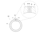
- FIG. 2 is an explanatory diagram showing a cross-sectional aspect of an electric resistance welded steel pipe.
- FIG. 2 is a flow diagram showing a method for manufacturing an electric resistance welded steel pipe.
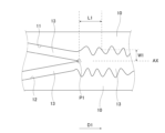
- FIG. 3 is an explanatory view showing an aspect of the welding step in FIG. 2 .
- Fig. 1 shows a cross section perpendicular to the axial direction of an electric resistance welded steel pipe 100.
- the electric resistance welded steel pipe 100 has a base material portion 10 and an electric resistance welded portion 20 that connects one end portion 11 of the base material portion 10 and the other end portion 12 of the base material portion 10.
- the electric resistance welded steel pipe 100 is formed in a cylindrical shape in this embodiment.
- the base material portion 10 has a C-shaped cross section perpendicular to the axial direction of the electric-welded steel pipe 100.
- the electric-welded welded portion 20 is formed by heating and melting the base material portion 10, and is also called a bead.
- the electric-welded welded portion 20 is disposed between one end 11 side and the other end 12 side of the base material portion 10 in the circumferential direction of the electric-welded steel pipe 100.
- a heat-affected zone 30 is disposed between the base material portion 10 and the electric-welded welded portion 20 in the circumferential direction.
- the base material portion 10 and the electric resistance welded portion 20 contain at least one of Cr, Cu, and Mo. In other words, as long as the base material portion 10 and the electric resistance welded portion 20 have one of these three components, the content of the other components may be "0 mass %".
- the concentration (mass %) of Cr in the base material portion 10 is expressed as [Cr] B
- the concentration (mass %) of Cr in the electric resistance welded portion 20 is expressed as [Cr] W .
- the concentration (mass %) of Cu in the base material portion 10 is expressed as [Cu] B
- the concentration (mass %) of Cu in the electric resistance welded portion 20 is expressed as [Cu] W .
- the concentration (mass %) of Mo in the base material portion 10 is expressed as [Mo] B
- the concentration (mass %) of Mo in the electric resistance welded portion 20 is expressed as [Mo] W .
- the base material portion 10 contains 0.02 mass % or more of Cr, it satisfies formula (1); when it contains 0.02 mass % or more of Cu, it satisfies formula (2); and when it contains 0.02 mass % or more of Mo, it satisfies formula (3).
- the sum of the concentrations of Cr, Mo, and Cu in the base material 10 is preferably 0.05% or more, and more preferably 0.10% or more. If the sum of the concentrations of Cr, Mo, and Cu exceeds 7.00%, the ductility and toughness of the electric resistance welded portion 20 will decrease, and cracks will be more likely to occur in the electric resistance welded portion 20. Therefore, the sum of the concentrations of Cr, Mo, and Cu in the base material 10 is preferably 7.00% or less, and more preferably 6.00% or less.
- the electric welded portion 20 contains Cr oxides.
- the Cr concentration is low around the Cr oxides, which reduces corrosion resistance.
- corrosion resistance can be evaluated based on the corrosion rate and pitting growth rate in a corrosion test described below. If the corrosion rate in a corrosion test is, for example, 0.100 mm/year or less and the pitting growth rate is 0.100 mm/year or less, the corrosion resistance is evaluated as being sufficient, good, etc.
- the Cr concentration in the electric welded portion 20 will be higher than that in the base material portion 10. Since the Cr concentration in the portion excluding the Cr oxides will be lower, the corrosion resistance of the electric welded portion 20 will decrease.
- the concentration of Cr in the electric resistance welded portion 20 relative to the base material portion 10, i.e., [Cr] W /[Cr] B is 1.50 or less. Having [Cr] W /[Cr] B of 1.50 or less makes it possible to ensure corrosion resistance in the electric resistance welded portion 20.
- [Cr] W /[Cr] B is preferably 1.40 or less, and more preferably 1.30 or less.
- [Cr] W /[Cr] B is preferably 0.50 or more.
- [Cr] W /[Cr] B is more preferably 0.60 or more, and further preferably 0.70 or more.
- Cu is less susceptible to oxidation at high temperatures than Fe. For this reason, Fe is preferentially oxidized in the electric welded portion 20, and Cu becomes concentrated. If concentrated Cu remains in the electric welded portion 20, the concentration of Cu in the electric welded portion 20 will be higher than in the base material portion 10. The difference in Cu concentration between the base material portion 10 and the electric welded portion 20 may form a local battery, reducing the corrosion resistance of the heat-affected portion 30.
- the Cu concentration in the electric resistance welded portion 20 relative to the base material portion 10, i.e., [Cu] W /[Cu] B is 1.50 or less.
- [Cu] W /[Cu] B is preferably 1.40 or less, and more preferably 1.30 or less. If the Cu concentration of the electric resistance welded portion 20 is too low compared to the base material portion 10, the corrosion resistance of the electric resistance welded portion 20 may decrease.
- [Cu] W /[Cu] B is preferably 0.50 or more, more preferably 0.60 or more, and even more preferably 0.70 or more.
- Mo is an element that improves the corrosion resistance of steel. By making the total concentration of Cr, Cu, and Mo in the base material 10 0.02% or more, sufficient corrosion resistance can be obtained in the base material 10.
- [Mo] W /[Mo] B is 1.50 or less, preferably 1.40 or less, and more preferably 1.30 or less.
- [Mo]W/[Mo]B is 0.50 or more, preferably 0.60 or more, and more preferably 0.70 or more.
- the corrosion resistance of the heat-affected zone 30 can be ensured. Specifically, Mo in steel is less likely to oxidize at high temperatures than Fe. Therefore, in the electric resistance welded zone 20, Fe is preferentially oxidized and Mo is concentrated. If concentrated Mo remains in the electric resistance welded zone 20, the concentration of Mo in the electric resistance welded zone 20 becomes higher than that in the base material portion 10. In such a state, a local battery is formed due to the difference in Mo concentration between the base material portion 10 and the electric resistance welded zone 20, and the corrosion resistance of the heat-affected zone 30 may be reduced. In addition, by making [Mo] W /[Mo] B 0.50 or more, the corrosion resistance of the electric resistance welded zone 20 can be further improved.
- [Cr] W , [Cr] B , [Cu] W , [Cu] B , [Mo] W , and [Mo] B can be measured using an EPMA (Electron Probe Micro Analyzer) method.
- the concentrations of the base metal portion 10 and the electric resistance welded portion 20 can both be measured using a cross section perpendicular to the axial direction of the electric resistance welded steel pipe 100 as the measurement surface.
- the beam diameter can be set to 1 ⁇ m.
- the concentration of the components in the base material 10 was measured at a position 90 degrees circumferentially away from the electric resistance welded portion 20. Also, the concentration of the components in the electric resistance welded portion 20 was measured at its center.
- [Cr] B , [Cu] B and [Mo] B can be determined by averaging a total of nine measurements at 1 ⁇ m intervals in the circumferential direction at a depth of 1 mm from the inner surface, centered on a position 90 degrees circumferentially away from the electric resistance welded portion 20.
- [Cr] W , [Cu] W and [Mo] W can be determined by averaging the values measured at a total of nine points circumferentially at 1 ⁇ m intervals at a position 1 mm deep from the inner surface, centered on the electric welded portion 20.
- the composition of the base material portion 10 is, in mass%, C: 0.020% or more and 0.200% or less, Si: 0.50% or less, Mn: 0.50% or more and 2.00% or less, P: 0.050% or less, S: 0.0200% or less, Al: 0.005% or more and 0.100% or less, and N: 0.0100% or less, Including, moreover, Cr: 5.00% or less, Cu: 2.00% or less, and Mo: 2.00% or less, At least one of the following is included: The balance preferably consists of Fe and unavoidable impurities. In this specification, unless otherwise specified, "%" indicating the steel composition is "mass %".
- C 0.020% or more and 0.200% or less C is an element that increases the strength of steel through solid solution strengthening. C also reduces the transformation start temperature, thereby refining crystal grains and increasing the strength of steel. By containing 0.020% or more of C, the base material portion 10 can obtain such effects.
- the base material 10 contains excessive C, an excessive amount of hard structure is generated in the electric resistance welded portion 20. As a result, the hardness of the electric resistance welded portion 20 increases, and the ductility and toughness of the electric resistance welded portion 20 decrease. In addition, local batteries may be formed due to the difference in material between the base material 10 and the electric resistance welded portion 20, which may decrease the corrosion resistance of the heat-affected portion 30.
- the C content in the base material 10 should be 0.200% or less, preferably 0.180% or less, and more preferably 0.170% or less.
- the C content in the base material 10 should be 0.020% or more, preferably 0.025% or more, and more preferably 0.030% or more.
- the C content in the base material 10 should be 0.025% or more and 0.180% or less, and more preferably 0.030% or more and 0.170% or less.
- Si 0.50% or less Si is an element that increases the strength of steel by solid solution strengthening.
- the base material 10 can obtain such an effect by containing 0.02% or more Si. If the base material 10 contains an excessive amount of Si, the hardness of the electric resistance welded portion 20 increases. As a result, the ductility and toughness of the electric resistance welded portion 20 decrease. In addition, a local cell may be formed due to the material difference between the base material 10 and the electric resistance welded portion 20, which may decrease the corrosion resistance of the heat-affected portion 30.
- the base material 10 may contain 0.50% or less Si, preferably 0.40% or less, and more preferably 0.30% or less.
- the base material 10 may contain 0.05% to 0.40% Si, and more preferably 0.08% to 0.30% Si.
- Mn 0.50% or more and 2.00% or less Mn is an element that increases the strength of steel by solid solution strengthening. Mn also reduces the transformation start temperature, thereby refining crystal grains and increasing the strength of steel. By containing 0.50% or more of Mn, the base material portion 10 can obtain such effects.
- the base material 10 contains excessive Mn, an excessive amount of hard structure is generated in the electric resistance welded portion 20. As a result, the hardness of the electric resistance welded portion 20 increases, and the ductility and toughness of the electric resistance welded portion 20 decrease. In addition, local batteries may be formed due to the difference in material between the base material 10 and the electric resistance welded portion 20, which may decrease the corrosion resistance of the heat-affected portion 30.
- the base material portion 10 preferably contains 0.05% or more Mn, more preferably 0.60% or more, and even more preferably 0.70% or more.
- the base material portion 10 preferably contains 2.00% or less Mn, more preferably 1.90% or less, and even more preferably 1.80% or less.
- the base material portion 10 preferably contains 2.00% or less Mn, more preferably 0.60% or more and 1.90% or less, and even more preferably 0.70% or more and 1.80% or less.
- P 0.050% or less
- P is an element that segregates at grain boundaries and reduces toughness. P corresponds to an inevitable impurity.
- the base material portion 10 should contain P at the lowest possible content, preferably 0.050% or less, more preferably 0.040% or less, and even more preferably 0.030% or less. There is no particular lower limit for the P content, but excessive reduction leads to high smelting costs. For this reason, the P content is preferably 0.001% or more.
- S 0.0200% or less S is usually present in steel as MnS.
- the steel material before the base material portion 10 is formed is thinly drawn in a hot rolling process.
- MnS has an adverse effect on the ductility and toughness of the steel material in the hot rolling process.
- the base material 10 preferably has an S content as low as possible.
- the base material 10 preferably has an S content of 0.0200% or less, more preferably 0.0100% or less, and even more preferably 0.0050% or less.
- S content is no particular lower limit for the S content, but excessive reduction will lead to increased smelting costs. For this reason, it is preferable that the S content be 0.0001% or more.
- Al 0.005% or more and 0.100% or less Al is an element that acts as a strong deoxidizer.
- the base material portion 10 can obtain such an effect by containing 0.005% or more of Al. If the base material portion 10 contains excessive Al, the weldability deteriorates and the amount of alumina-based inclusions increases, deteriorating the surface properties of the base material portion 10.
- the base material portion 10 may contain 0.100% or less Al, preferably 0.080% or less, and more preferably 0.070% or less.
- the base material portion 10 may contain 0.010% to 0.080% Al, and more preferably 0.015% to 0.070% Al.
- N 0.0100% or less
- N is an inevitable impurity and an element that strongly fixes dislocation motion, thereby reducing the ductility and toughness of the base material portion 10. It is preferable that the base material portion 10 contains N at as low a content as possible. The N content is permissible up to 0.0100%.
- the N content of the base material portion 10 is preferably 0.0100% or less, preferably 0.0080% or less, and more preferably 0.0060% or less.
- Cr 5.00% or less
- Cr is an element that improves corrosion resistance.
- Cr is an element that contributes to refining the structure by lowering the transformation start temperature, and increases the strength of the steel.
- the base material portion 10 can obtain such effects by containing 0.01% or more of Cr. If the base material portion 10 contains excessive Cr, the ductility and toughness are reduced.
- the base material 10 contains excessive Cr, the hardness of the electric resistance welded portion 20 may increase, and the corrosion resistance of the heat-affected portion 30 may decrease. If the base material 10 contains excessive Cr, a large amount of Cr oxide may be produced in the electric resistance welded portion 20, and the corrosion resistance of the electric resistance welded portion 20 may decrease.
- the base material portion 10 preferably contains 5.00% or less Cr, more preferably 3.00% or less, and even more preferably 2.00% or less.
- the base material portion 10 preferably contains 0.02% or more Cr, and more preferably 0.05% or more.
- the base material portion 10 preferably contains 0.05% or more and 2.00% or less Cr.
- Cu 2.00% or less
- Cu is an element that improves corrosion resistance.
- Cu is also an element that increases the strength of steel by solid solution strengthening.
- Cu is an element that contributes to refining the structure by lowering the transformation start temperature, and increases the strength of steel.
- the base material portion 10 can obtain such effects by containing 0.01% or more of Cu. If the base material portion 10 contains an excessive amount of Cu, the ductility and toughness are reduced. Furthermore, if the base material portion 10 contains an excessive amount of Cu, the hardness of the electric welded portion 20 increases, and the corrosion resistance of the heat-affected portion 30 may decrease. Furthermore, even if Cu is added to the base material portion 10 in an amount exceeding the solid solubility limit, Cu precipitates are formed and the amount of solid solubility of Cu in the steel does not increase. Therefore, the effect of improving corrosion resistance relative to the amount added is not obtained.
- the base material portion 10 may contain 2.00% or less of Cu, preferably 1.80% or less, and more preferably 1.60% or less.
- the base material portion 10 may contain 0.02% or more of Cu, and more preferably 0.05% or more.
- the base material portion 10 preferably contains Cu in an amount of 0.02% or more and 1.80% or less, and more preferably contains Cu in an amount of 0.05% or more and 1.60% or less.
- Mo 2.00% or less Mo is an element that contributes to the refinement of the structure by lowering the transformation start temperature and increases the strength of the steel.
- the base material portion 10 can obtain these effects by containing Mo at 0.01% or more. If the base material portion 10 contains Mo excessively, the ductility and toughness are reduced. In addition, if the base material portion 10 contains Mo excessively, the hardness of the electric resistance welded portion 20 may increase and the corrosion resistance of the heat-affected portion 30 may decrease.
- the base material portion 10 may contain Mo at 2.00% or less, preferably at 1.80% or less, and more preferably at 1.60% or less.
- the base material portion 10 may contain Mo at 0.02% or more, and more preferably at 0.05% or more.
- the base material portion 10 preferably contains Mo in an amount of 0.02% or more and 1.80% or less, and more preferably contains Mo in an amount of 0.05% or more and 1.60% or less.
- the base material 10 contains Fe and unavoidable impurities as the remainder.
- the electric welded steel pipe according to one embodiment of the present invention may contain only the above components and the remainder, with the remainder being Fe and unavoidable impurities.
- Inevitable impurities are impurities that are inevitably mixed in from raw materials, manufacturing processes, manufacturing equipment, etc., and are permitted to be included to the extent that does not impair the purpose of the present invention.
- raw materials include iron ore, reduced iron, and scrap.
- unavoidable impurities in the remainder include Mg, Zr, REM, Sn, As, Sb, Bi, Co, Pb, Zn, O, Ta, W, Te, Hf, Ge, Sr, Cs, etc.
- REM is a general term for Sc, Y, and a total of 17 elements including lanthanoid elements.
- the base material 10 can contain at least one of these 17 elements as an unavoidable impurity.
- the content of REM in the base material 10 is the total content of these elements.
- the composition of the base material portion 10 is further expressed as follows, in mass %, Nb: 0.080% or less, V: 0.080% or less, Ti: 0.080% or less, Ni: 2.00% or less, Ca: 0.0050% or less, B: 0.0050% or less, Sn: 0.100% or less.
- Nb, V, Ni, Ca, B, and Sn are elements that may be optionally contained in the base material portion 10. Therefore, the content of these components in the base material portion 10 may be "0 mass %".
- Nb 0.080% or less Nb forms fine carbides and nitrides in steel, thereby contributing to improving the strength of the steel. Nb also suppresses coarsening of the structure during hot rolling, thereby contributing to refinement of the structure and increasing the strength of the steel.
- the base material 10 can achieve this effect by containing 0.002% or more Nb. If the base material 10 contains too much Nb, the ductility and toughness will decrease.
- the base material portion 10 may contain 0.080% or less Nb, preferably 0.070% or less, and more preferably 0.060% or less.
- the base material portion 10 may contain 0.005% or more Nb, and more preferably 0.010% or more.
- the base material portion 10 may contain 0.005% or more to 0.070% or less Nb, and more preferably 0.010% or more to 0.060% or less Nb.
- V 0.080% or less V is an element that contributes to improving the strength of steel by forming fine carbides and nitrides in the steel. By including 0.002% or more of V in the base material portion 10, such an effect can be obtained.
- the base material 10 should contain 0.080% or less V, preferably 0.070% or less, and preferably 0.060% or less.
- the base material 10 should preferably contain 0.005% or more V, and preferably 0.010% or more V.
- the base material 10 should preferably contain 0.005% or more and 0.070% or less V, and preferably 0.010% or more and 0.060% or less V.
- Ti 0.080% or less Ti is an element that contributes to improving the strength of steel by forming fine carbides and nitrides in steel. In addition, Ti is an element that contributes to reducing the amount of solute N in steel because of its high affinity with N.
- the base material portion 10 preferably contains 0.002% or more of Ti.
- the base material 10 contains excessive Ti, the ductility and toughness will decrease. If the base material 10 contains Ti, it should contain 0.080% or less, preferably 0.070% or less, and more preferably 0.060% or less. The base material 10 should preferably contain 0.005% or more Ti, and more preferably 0.010% or more. The base material 10 should preferably contain 0.005% or more and 0.070% or less Ti, and more preferably 0.010% or more and 0.060% or less Ti.
- Ni 2.00% or less
- Ni is an element that increases the strength of steel by solid solution strengthening. Ni also contributes to the refinement of the structure by lowering the transformation start temperature, and increases the strength of steel.
- the base material portion 10 can obtain such effects by containing Ni at 0.01% or more. If the base material portion 10 contains excessive Ni, the ductility and toughness are reduced. If the base material portion 10 contains excessive Ni, the hardness of the electric resistance welded portion 20 may increase, and the corrosion resistance of the heat-affected portion 30 may decrease.
- the base material portion 10 may contain Ni at 2.00% or less, preferably at 1.80% or less, and more preferably at 1.60% or less.
- the base material portion 10 may contain Ni at 0.02% or more, and more preferably at 0.05% or more.
- the base material portion 10 preferably contains Ni in an amount of 0.02% or more and 1.80% or less, and more preferably contains Ni in an amount of 0.05% or more and 1.60% or less.
- Ca 0.0050% or less Ca is an element that contributes to improving the toughness of steel by spheroidizing sulfides such as MnS that are thinly drawn in the hot rolling process.
- the base material portion 10 can obtain these effects by containing 0.0005% or more of Ca. If the base material portion 10 contains excessive Ca, Ca oxide clusters are formed in the steel, and the toughness deteriorates.
- the base material portion 10 it is preferable that it contains 0.0050% or less, preferably 0.0040% or less, and more preferably 0.0035% or less.
- the base material portion 10 preferably contains 0.0008% or more of Ca, and more preferably 0.0010% or more.
- the base material portion 10 preferably contains 0.0008% or more and 0.0040% or less of Ca, and more preferably 0.0010% or more and 0.0035% or less of Ca.
- B 0.0050% or less B is an element that contributes to the refinement of the structure by lowering the transformation start temperature and increases the strength of the steel.
- the base material portion 10 can obtain such effects by containing 0.0002% or more of B. If the base material portion 10 contains too much B, the ductility and toughness are reduced. In addition, if the base material portion 10 contains too much B, the hardness of the electric resistance welded portion 20 may increase and the corrosion resistance of the heat-affected portion 30 may decrease. For this reason, if the base material portion 10 contains B, it is preferable that it contains 0.0050% or less of B, preferably 0.0005% or more and 0.0040% or less, and more preferably 0.0008% or more and 0.0030% or less of B.
- Sn 0.100% or less Sn is an element that suppresses decarburization caused by nitriding or oxidation of the steel surface and suppresses the decrease in strength.
- the base material portion 10 can obtain such effects by containing 0.001% or more of Sn. If the base material portion 10 contains excessive Sn, the ductility and toughness decrease. Therefore, when the base material portion 10 contains Sn, it is preferable that the base material portion 10 contains 0.100% or less of Sn.
- the base material portion 10 preferably contains 0.080% or less of Sn, and more preferably contains 0.060% or less of Sn.
- the base material portion 10 preferably contains 0.001% or more of Sn, preferably contains 0.002% or more, and more preferably contains 0.005% or more of Sn.
- the Vickers hardness at a position 1 mm deep from the inner surface of the base material 10 is referred to as the base material hardness HB
- the Vickers hardness at a position 1 mm deep from the inner surface of the electric resistance welded portion 20 is referred to as the electric resistance welded portion hardness HW.
- the absolute value of the difference between the base material hardness HB and the electric resistance welded portion hardness HW is preferably 100 HV or less, that is,
- 2HV or more, and preferably 5HV or more.
- the base material hardness (HB) and the electric resistance welded portion hardness (HW) can be measured by a Vickers test. This test can be performed according to the method described in JIS Z 2244 (2020). In this test, the base material 10 and the electric resistance welded portion 20 are both measured at a cross section perpendicular to the axial direction of the electric resistance welded steel pipe 100, and the test is performed under a load of 1 kgf.
- the base material hardness (HB) and the electric resistance welded portion hardness (HW) can be obtained, for example, by averaging the values obtained by measuring the hardness at three points at each test portion.
- the base material hardness (HB) can be measured at a position on the base material 10 that is 90 degrees away from the electric resistance welded portion 20 in the circumferential direction.
- the electric resistance welded portion hardness (HW) can be measured at the electric resistance welded portion 20.
- the electric welded steel pipe 100 preferably has a yield strength of 400 MPa or more, and more preferably 450 MPa or more. With a yield strength of 400 MPa or more, the electric welded steel pipe 100 can have sufficient internal pressure resistance.
- the yield strength of the electric resistance welded steel pipe 100 becomes high, the corrosion resistance of the electric resistance welded steel pipe 100 may decrease. Therefore, the yield strength is preferably 1100 MPa or less, and more preferably 1000 MPa or less.
- the yield strength can be measured by a tensile test. The tensile test is performed in accordance with the provisions of JIS Z 2241. The yield strength (MPa) is the flow stress at a nominal strain of 0.5%.
- a JIS No. 5 tensile test specimen is used for the tensile test. The test specimen is taken from the base material 10 so that the tensile direction is parallel to the axial direction of the electric resistance welded steel pipe 100.
- the base material portion 10 and the electric resistance welded portion 20 of the electric resistance welded steel pipe 100 have a predetermined corrosion rate and pitting growth rate.
- the corrosion rate and pitting growth rate can be measured by the following corrosion test.
- the test pieces used in the corrosion test are mirror-polished on all sides and degreased with acetone.
- the corrosion test is performed by exposing the test pieces to an environment of a mixture of SO2 , NO2 , O2 , H2O , and CO2 gases at a temperature and pressure of 50°C and 10 MPa.
- the test time is 72 hours (3 days).
- the test specimen is derusted according to ASTM standard G1-03, and the corrosion rate is determined.
- the pitting growth rate (unit: mm/year) is calculated by measuring the maximum pitting depth (unit: mm) on the surface of the test specimen and multiplying this value by 365/3.
- the maximum pitting depth is determined by a microscopic method according to ASTM standard G46-94.
- the base material portion 10 and the electric resistance welded portion 20 should have a corrosion rate of 0.100 mm/year or less in the above corrosion test, and preferably 0.090 mm/year or less.
- the base material portion 10 and the electric resistance welded portion 20 should have a pitting growth rate of 0.100 mm/year or less in the above corrosion test, and preferably 0.090 mm/year or less.
- FIG. 2 shows the manufacturing flow of electric-resistance welded steel pipe.
- the method for manufacturing electric-resistance welded steel pipe includes a hot-rolled steel plate production process (step S01) in which a steel material is hot-rolled to form a hot-rolled steel plate, and a pipe forming process (step S02) in which the hot-rolled steel plate is formed into an open pipe.
- the method for manufacturing electric-resistance welded steel pipe also includes a welding process (step S03) in which one end and the other end of the open pipe are electric-resistance welded.
- the surface temperature of hot-rolled steel sheets can be measured using a radiation thermometer, etc.
- a steel material having the above-mentioned composition is heated and hot-rolled. Specifically, a steel material containing Cu, Cr, and Mo in a total amount of 0.02 mass% or more is hot-rolled. The hot-rolled steel material is cooled and then wound into a coil to produce a hot-rolled steel sheet.
- Steel material is also called steel slab.
- the method for melting steel material and known melting methods such as converters, electric furnaces, and vacuum melting furnaces may be used.
- method for casting steel material and known casting methods such as continuous casting may be used. Steel material is produced to a specified size by casting. Note that instead of continuous casting, an ingot casting and blooming rolling method may be applied. The molten steel may further be subjected to secondary refining such as ladle refining.
- the tube is formed into a cylindrical shape, for example, by cold roll forming.
- the open tube formed in the tube forming process has a C-shaped cross section perpendicular to the axial direction of the tube.
- the open tube is formed with a portion open in the circumferential direction.
- the opening of the open tube is formed along the axial direction of the tube.
- the heating method for the electric resistance welding performed in the welding process of step S03 can be, for example, electric current heating or induction heating.
- the welding process of step S03 is performed in a state that satisfies the following (Condition 1) to (Condition 3).
- Condition 1 is achieved, for example, by adjusting at least one of the pipe-making speed, the heating start position, and the squeeze roll spacing.
- the time for the center of the welded part in the thickness direction to reach 1000°C or higher is long, the amount of Cr oxide generated in the welded part increases. Therefore, Cr oxide remains in the electric welded part 20, the Cr concentration in the electric welded part 20 increases, and the corrosion resistance of the electric welded part 20 may decrease. Also, if the time for the center of the welded part in the thickness direction to reach 1000°C or higher is long, the amount of Cu and Mo that concentrates in the welded part increases. Therefore, the concentrations of Cu and Mo in the electric welded part 20 increase, and the corrosion resistance of the heat-affected part 30 may decrease.
- the time for the center of the welded part in the thickness direction to reach 1000°C or higher is 1.0 seconds or less, and preferably 0.8 seconds or less.
- the temperature of the center of the welded part in the thickness direction can be measured using a two-color thermometer.
- the temperature measurement site of the center of the welded part in the thickness direction can be, for example, a position 20 mm away from the welding start point P1 in the opposite direction to the pipe-making direction D1.
- Condition 2 is achieved, for example, by adjusting the composition of the air in the atmosphere in which the welded parts are placed. Specifically, the oxygen concentration in the atmosphere in which the welded parts are placed is reduced by spraying nitrogen gas or argon gas onto the welded parts. This reduces the oxygen concentration in the welded parts. Note that an enclosure may be provided around the welded parts to make it easier to control the oxygen concentration in the atmosphere. The oxygen concentration in the welded parts can be calculated from the measurement data by measuring the oxygen concentration in the atmosphere with an oxygen concentration meter.
- the oxygen concentration in the welded part is high, the amount of Cr oxides produced in the welded part increases. Cr oxides remain in the electric welded part, which increases the Cr concentration in the electric welded part and may reduce the corrosion resistance of the electric welded part. Furthermore, when the oxygen concentration in the welded part is high, the amount of Fe oxidized increases, which increases the amount of Cu and Mo concentrated in the welded part. This increases the Cu and Mo concentrations in the electric welded part and may reduce the corrosion resistance of the heat-affected zone. For this reason, the oxygen concentration in the welded part is 0.10 mass% or less, and preferably 0.08 mass% or less.
- Condition 3 is achieved by adjusting the welding power, pipe-making speed, and squeeze roll spacing so that the amount of molten steel discharged is at least 0.2 times the plate thickness.
- Figure 3 shows the state of the welding process. As shown in Figure 3, when electric resistance welding is started, molten steel 13 is formed. Electric resistance welding is performed from the welding start point P1 toward the pipe-making direction D1.
- the amount of molten steel discharged is expressed as length (mm) by setting the length (mm) per pixel in advance and calculating the length (mm) on the screen when continuously photographing the welded part with a high-speed camera.
- the amount of molten steel discharged is determined by continuously photographing the welded part with a high-speed camera. Specifically, the molten steel width W1 is photographed with the high-speed camera for one second at 2000 fps.
- the molten steel discharge amount is determined by averaging the values of 2000 photographed points. For example, a two-dimensional image sensor camera with a high-speed shutter is installed above the welding point to capture still images of the area around the welding point. The photographed image is then binarized to determine the molten steel portion and calculate the amount corresponding to the molten steel portion.
- the molten steel width W1 should be measured at a distance L1 downstream in the pipe-making direction from the welding start point P1.
- the welding start point P1 can be determined, for example, as follows.
- the butt end surface corresponding to the pipe edge of the open pipe is detected as a point cloud using image processing.
- two straight lines corresponding to the butt end surface are calculated using the least squares method. The intersection of the two calculated straight lines is determined, and this intersection can be used as the welding start point P1.
- the molten steel width W1 can be measured as the distance from the axis AX of the electric resistance welded steel pipe 100 to the base material portion 10.
- the distance L1 should be twice the thickness of the plate.
- the amount of molten steel discharged should be 0.2 times or more the thickness of the plate, and preferably 0.3 times or more.
- the amount of molten steel discharged is large, the welded part will be excessively molten, and the upset will not be sufficiently achieved. As a result, Cr oxides will not be sufficiently discharged and will remain in the electric welded part 20, which may reduce the corrosion resistance of the electric welded part 20. In addition, concentrated Cu and Mo will not be sufficiently discharged and will remain in the electric welded part 20, which may reduce the corrosion resistance of the heat-affected part 30. For this reason, it is preferable that the amount of molten steel discharged be 3.0 times or less the thickness of the plate. More preferably, it is 2.0 times or less the thickness of the plate.
- heat treatment can be performed to adjust the hardness of the electric resistance welded portion 20.
- the entire electric resistance welded steel pipe 100 may be heat treated, or only the electric resistance welded portion 20 may be heat treated.
- the heating method for heat treatment is, for example, induction heating, but is not limited to this method, and a heating furnace may also be used.
- Whether or not a steel pipe is an electric resistance welded steel pipe can be determined by measuring the width of the electric resistance weld 20 on a cut surface cut perpendicular to the axial direction of the steel pipe. For example, when the cut surface of the steel pipe is corroded, the electric resistance weld 20 can be visually recognized as an area that has a different structure and contrast from the base material 10 and the heat-affected zone 30.
- an electric resistance welded steel pipe 100 made of carbon steel and low alloy steel is corroded with nital and observed under an optical microscope, it appears whiter than the base material portion 10 and the heat-affected portion 30.
- An example of an electric resistance welded steel pipe 100 made of carbon steel and low alloy steel is a UOE steel pipe.
- the electric resistance welded portion 20 of a UOE steel pipe is corroded with nital and observed under an optical microscope, a cellular or dendritic solidification structure is visible.
- the corroding solution used to corrode the steel pipe should be selected appropriately depending on the steel components and the type of steel pipe.
- the width of the electric resistance welded portion 20 observed in this way in the pipe circumferential direction is 1.0 ⁇ m or more and 1000 ⁇ m or less over the entire thickness of the pipe, it can be identified as an electric resistance welded steel pipe.
- the electric resistance welded steel pipe 100 described above can be used, for example, as a line pipe that constitutes a pipeline connecting one point to another point.
- a pipeline is composed of multiple line pipes, by using the electric resistance welded steel pipe 100 described above for at least one of the line pipes, it is possible to increase the corrosion resistance of the location where the line pipe is arranged.
- Molten steel having the chemical composition shown in Table 1 was produced, and a slab was obtained as the steel material.
- the obtained slab was heated and hot-rolled, cooled, and then wound into a coil to produce a hot-rolled steel sheet with the thickness (indicated as plate thickness in Table 2) (mm) shown in Table 2.
- the hot-rolled steel sheet was then formed into a cylindrical shape by cold rolling, and electric resistance welding was performed under the conditions shown in Table 2 to produce an electric resistance welded steel pipe with the outer diameter (mm) and wall thickness (mm) shown in Table 2.
- Test pieces were taken from the obtained electric resistance welded steel pipes, and the following elemental concentration measurements, tensile tests, Vickers tests, and corrosion tests were carried out.
- the amount of molten steel discharged (mm) was obtained by continuously photographing the welded part with a high-speed camera. Specifically, the length (mm) per pixel was set in advance, and the length (mm) on the screen was calculated. The molten steel width W1 was photographed with the high-speed camera for 1 second under the condition of 2000 fps. The average value of the 2000 photographed points was determined as the amount of molten steel discharged.
- the molten steel width W1 was measured at a distance L1 downstream from the welding start point P1 in the pipe-making direction.
- the welding start point P1 was set as follows. In an image of the open pipe, the butt end surface corresponding to the pipe edge was detected as a point cloud by image processing. From the detected point cloud, two straight lines corresponding to the butt end surface were calculated by the least squares method. The intersection of the two calculated straight lines was found, and this intersection was set as the welding start point P1.
- the molten steel width W1 was measured as the distance from the axis AX of the electric resistance welded steel pipe 100 to the base material portion 10. It is advisable to set the distance L1 to twice the thickness of the plate. The nominal plate thickness of the hot-rolled plate was used for the plate thickness.
- the element concentrations of the base material and the electric resistance welded portion were measured by the EPMA method.
- the measurement surfaces of both the electric resistance welded portion and the base material were cross sections perpendicular to the pipe axis direction.
- the beam diameter was 1 ⁇ m.
- [Cr] B , [Cu] B , and [Mo] B were measured at nine points at 1 ⁇ m intervals in the circumferential direction at a position 1 mm deep from the inner surface, centered on a position 90 degrees away from the electric resistance weld 20, and the values were averaged.
- [Cr] W , [Cu] W , and [Mo] W were measured at nine points at 1 ⁇ m intervals in the circumferential direction at a position 1 mm deep from the inner surface, centered on the electric resistance weld, and the values were averaged.
- the tensile test was carried out in accordance with the provisions of JIS Z 2241.
- the yield strength (MPa) was defined as the flow stress at a nominal strain of 0.5%.
- the test specimens used in the tensile test were JIS No. 5 tensile test specimens. The test specimens were taken from the base material so that the tensile direction was parallel to the axial direction of the electric resistance welded steel pipe.
- Test pieces were taken from the base material and the electric resistance welded part.
- the dimensions of the test piece were 3 mm thick x 10 mm wide x 25 mm long.
- the width direction of the test piece was parallel to the circumferential direction of the electric resistance welded steel pipe.
- the length direction of the test piece was parallel to the axial direction of the electric resistance welded steel pipe.
- the test pieces were taken so that the center of the thickness was 2.5 mm deep from the inner surface.
- the test pieces of the electric resistance welded part were taken so that the electric resistance welded part was located in the center of the width.
- the test pieces used in the corrosion test were mirror-polished on all sides and then degreased with acetone.
- the corrosion test was performed by exposing the test pieces to an environment in which a gas mixture of SO2, NO2 , O2 , H2O , and CO2 was heated and pressurized to 50°C and 10 MPa.
- the test time was 72 hours (3 days).
- the gas used was CO2 containing, by volume fraction, 50 ppm SO2 , 300 ppm NO2 , 100 ppm O2 , and 600 ppm H2O .
- the test pieces were derusted in accordance with ASTM standard G1-03, and the corrosion rate was determined.
- the pitting growth rate (unit: mm/year) was calculated by measuring the maximum pitting depth (unit: mm) on the surface of the test piece and multiplying this value by 365/3.
- the maximum pitting depth was determined by a microscopic method in accordance with ASTM standard G46-94. The results are shown in Table 3.
- All of the electric - resistance welded steel pipes of the present invention examples satisfy the following: [Cr] B + [Mo] B + [Cu] B ⁇ 0.02; [Cr] W /[Cr] B ⁇ 1.50 when [Cr] B ⁇ 0.20; [Mo] W /[Mo] B ⁇ 1.50 when [Mo] B ⁇ 0.20; and [Cu] W /[Cu] B ⁇ 1.50 when [Cu]B ⁇ 0.20.
Landscapes
- Chemical & Material Sciences (AREA)
- Engineering & Computer Science (AREA)
- Mechanical Engineering (AREA)
- Materials Engineering (AREA)
- Metallurgy (AREA)
- Organic Chemistry (AREA)
- Manufacturing & Machinery (AREA)
- Physics & Mathematics (AREA)
- Thermal Sciences (AREA)
- Crystallography & Structural Chemistry (AREA)
- Heat Treatment Of Steel (AREA)
Priority Applications (1)
| Application Number | Priority Date | Filing Date | Title |
|---|---|---|---|
| JP2024554685A JPWO2025099985A1 (https=) | 2023-11-09 | 2024-07-02 |
Applications Claiming Priority (2)
| Application Number | Priority Date | Filing Date | Title |
|---|---|---|---|
| JP2023191290 | 2023-11-09 | ||
| JP2023-191290 | 2023-11-09 |
Publications (1)
| Publication Number | Publication Date |
|---|---|
| WO2025099985A1 true WO2025099985A1 (ja) | 2025-05-15 |
Family
ID=95695368
Family Applications (1)
| Application Number | Title | Priority Date | Filing Date |
|---|---|---|---|
| PCT/JP2024/023975 Pending WO2025099985A1 (ja) | 2023-11-09 | 2024-07-02 | 電縫鋼管、ラインパイプ及び、電縫鋼管の製造方法 |
Country Status (2)
| Country | Link |
|---|---|
| JP (1) | JPWO2025099985A1 (https=) |
| WO (1) | WO2025099985A1 (https=) |
Citations (5)
| Publication number | Priority date | Publication date | Assignee | Title |
|---|---|---|---|---|
| WO2008105216A1 (ja) * | 2007-02-26 | 2008-09-04 | Jfe Steel Corporation | 熱処理用電縫溶接鋼管およびその製造方法 |
| JP2011025311A (ja) * | 2009-06-22 | 2011-02-10 | Jfe Steel Corp | 電縫溶接部の耐サワー特性に優れた高強度厚肉ラインパイプ向け電縫鋼管の製造方法 |
| JP2013234348A (ja) * | 2012-05-08 | 2013-11-21 | Jfe Steel Corp | 耐疲労特性に優れた自動車部品用電縫溶接鋼管およびその製造方法 |
| WO2020170333A1 (ja) * | 2019-02-19 | 2020-08-27 | 日本製鉄株式会社 | ラインパイプ用電縫鋼管 |
| JP2020143338A (ja) * | 2019-03-06 | 2020-09-10 | 日本製鉄株式会社 | 電縫鋼管 |
-
2024
- 2024-07-02 WO PCT/JP2024/023975 patent/WO2025099985A1/ja active Pending
- 2024-07-02 JP JP2024554685A patent/JPWO2025099985A1/ja active Pending
Patent Citations (5)
| Publication number | Priority date | Publication date | Assignee | Title |
|---|---|---|---|---|
| WO2008105216A1 (ja) * | 2007-02-26 | 2008-09-04 | Jfe Steel Corporation | 熱処理用電縫溶接鋼管およびその製造方法 |
| JP2011025311A (ja) * | 2009-06-22 | 2011-02-10 | Jfe Steel Corp | 電縫溶接部の耐サワー特性に優れた高強度厚肉ラインパイプ向け電縫鋼管の製造方法 |
| JP2013234348A (ja) * | 2012-05-08 | 2013-11-21 | Jfe Steel Corp | 耐疲労特性に優れた自動車部品用電縫溶接鋼管およびその製造方法 |
| WO2020170333A1 (ja) * | 2019-02-19 | 2020-08-27 | 日本製鉄株式会社 | ラインパイプ用電縫鋼管 |
| JP2020143338A (ja) * | 2019-03-06 | 2020-09-10 | 日本製鉄株式会社 | 電縫鋼管 |
Also Published As
| Publication number | Publication date |
|---|---|
| JPWO2025099985A1 (https=) | 2025-05-15 |
Similar Documents
| Publication | Publication Date | Title |
|---|---|---|
| KR950008377B1 (ko) | 용접가능한 개선된 페라이트 스텐레스강 | |
| CN109563594B (zh) | 耐硫酸露点腐蚀钢 | |
| JP6822623B1 (ja) | 耐硫酸露点腐食性に優れる継目無鋼管およびその製造方法 | |
| KR102154217B1 (ko) | 용접 구조 부재 | |
| CN109642287B (zh) | 耐硫酸露点腐蚀钢 | |
| CN111051553B (zh) | 高Mn钢及其制造方法 | |
| CN101765673B (zh) | 原油罐用热轧型钢及其制造方法 | |
| WO2013035588A1 (ja) | 二相ステンレス鋼 | |
| US20170073800A1 (en) | Ferritic stainless steel | |
| JP6566125B2 (ja) | 溶接構造部材 | |
| JP7444338B1 (ja) | 熱延厚物耐硫酸鋼板およびその製造方法 | |
| KR102597735B1 (ko) | 페라이트계 스테인리스 강판 및 그 제조 방법 | |
| CN114080465A (zh) | 耐硫酸露点腐蚀性优异的无缝钢管及其制造方法 | |
| CN105408511B (zh) | 焊接部的耐腐蚀性优良的铁素体系不锈钢 | |
| JP2009041103A (ja) | 排ガス再循環系部品用オーステナイト系ステンレス鋼およびその製造方法 | |
| JP6442852B2 (ja) | 二相ステンレス鋼溶接継手 | |
| JP7226595B2 (ja) | ラインパイプ用電縫鋼管 | |
| WO2025099985A1 (ja) | 電縫鋼管、ラインパイプ及び、電縫鋼管の製造方法 | |
| KR20260055512A (ko) | 전봉 강관, 라인 파이프 및 전봉 강관의 제조 방법 | |
| JP6771963B2 (ja) | 二相ステンレス鋼 | |
| JP2019026940A (ja) | 二相ステンレス鋼溶接継手 | |
| JPH09137255A (ja) | 溶接施工性に優れた高耐食オーステナイト系ステンレス鋼および溶接材料 | |
| JP3800150B2 (ja) | 製造性に優れるマルテンサイト系ステンレス熱延鋼帯 | |
| JP7758248B1 (ja) | 電縫鋼管、ラインパイプおよび電縫鋼管の製造方法 | |
| JP7816551B2 (ja) | 二相ステンレス鋼およびステンレス継目無鋼管 |
Legal Events
| Date | Code | Title | Description |
|---|---|---|---|
| ENP | Entry into the national phase |
Ref document number: 2024554685 Country of ref document: JP Kind code of ref document: A |
|
| WWE | Wipo information: entry into national phase |
Ref document number: 2024554685 Country of ref document: JP |
|
| 121 | Ep: the epo has been informed by wipo that ep was designated in this application |
Ref document number: 24888287 Country of ref document: EP Kind code of ref document: A1 |