WO2025095006A1 - 溶接継手 - Google Patents
溶接継手 Download PDFInfo
- Publication number
- WO2025095006A1 WO2025095006A1 PCT/JP2024/038724 JP2024038724W WO2025095006A1 WO 2025095006 A1 WO2025095006 A1 WO 2025095006A1 JP 2024038724 W JP2024038724 W JP 2024038724W WO 2025095006 A1 WO2025095006 A1 WO 2025095006A1
- Authority
- WO
- WIPO (PCT)
- Prior art keywords
- steel sheet
- plating layer
- less
- phase
- welded joint
- Prior art date
- Legal status (The legal status is an assumption and is not a legal conclusion. Google has not performed a legal analysis and makes no representation as to the accuracy of the status listed.)
- Pending
Links
Images


Classifications
-
- B—PERFORMING OPERATIONS; TRANSPORTING
- B23—MACHINE TOOLS; METAL-WORKING NOT OTHERWISE PROVIDED FOR
- B23K—SOLDERING OR UNSOLDERING; WELDING; CLADDING OR PLATING BY SOLDERING OR WELDING; CUTTING BY APPLYING HEAT LOCALLY, e.g. FLAME CUTTING; WORKING BY LASER BEAM
- B23K11/00—Resistance welding; Severing by resistance heating
- B23K11/10—Spot welding; Stitch welding
- B23K11/11—Spot welding
-
- B—PERFORMING OPERATIONS; TRANSPORTING
- B23—MACHINE TOOLS; METAL-WORKING NOT OTHERWISE PROVIDED FOR
- B23K—SOLDERING OR UNSOLDERING; WELDING; CLADDING OR PLATING BY SOLDERING OR WELDING; CUTTING BY APPLYING HEAT LOCALLY, e.g. FLAME CUTTING; WORKING BY LASER BEAM
- B23K11/00—Resistance welding; Severing by resistance heating
- B23K11/16—Resistance welding; Severing by resistance heating taking account of the properties of the material to be welded
-
- C—CHEMISTRY; METALLURGY
- C22—METALLURGY; FERROUS OR NON-FERROUS ALLOYS; TREATMENT OF ALLOYS OR NON-FERROUS METALS
- C22C—ALLOYS
- C22C21/00—Alloys based on aluminium
-
- C—CHEMISTRY; METALLURGY
- C22—METALLURGY; FERROUS OR NON-FERROUS ALLOYS; TREATMENT OF ALLOYS OR NON-FERROUS METALS
- C22C—ALLOYS
- C22C38/00—Ferrous alloys, e.g. steel alloys
-
- C—CHEMISTRY; METALLURGY
- C22—METALLURGY; FERROUS OR NON-FERROUS ALLOYS; TREATMENT OF ALLOYS OR NON-FERROUS METALS
- C22C—ALLOYS
- C22C38/00—Ferrous alloys, e.g. steel alloys
- C22C38/60—Ferrous alloys, e.g. steel alloys containing lead, selenium, tellurium, or antimony, or more than 0.04% by weight of sulfur
-
- C—CHEMISTRY; METALLURGY
- C23—COATING METALLIC MATERIAL; COATING MATERIAL WITH METALLIC MATERIAL; CHEMICAL SURFACE TREATMENT; DIFFUSION TREATMENT OF METALLIC MATERIAL; COATING BY VACUUM EVAPORATION, BY SPUTTERING, BY ION IMPLANTATION OR BY CHEMICAL VAPOUR DEPOSITION, IN GENERAL; INHIBITING CORROSION OF METALLIC MATERIAL OR INCRUSTATION IN GENERAL
- C23C—COATING METALLIC MATERIAL; COATING MATERIAL WITH METALLIC MATERIAL; SURFACE TREATMENT OF METALLIC MATERIAL BY DIFFUSION INTO THE SURFACE, BY CHEMICAL CONVERSION OR SUBSTITUTION; COATING BY VACUUM EVAPORATION, BY SPUTTERING, BY ION IMPLANTATION OR BY CHEMICAL VAPOUR DEPOSITION, IN GENERAL
- C23C2/00—Hot-dipping or immersion processes for applying the coating material in the molten state without affecting the shape; Apparatus therefor
- C23C2/04—Hot-dipping or immersion processes for applying the coating material in the molten state without affecting the shape; Apparatus therefor characterised by the coating material
- C23C2/12—Aluminium or alloys based thereon
-
- C—CHEMISTRY; METALLURGY
- C21—METALLURGY OF IRON
- C21D—MODIFYING THE PHYSICAL STRUCTURE OF FERROUS METALS; GENERAL DEVICES FOR HEAT TREATMENT OF FERROUS OR NON-FERROUS METALS OR ALLOYS; MAKING METAL MALLEABLE, e.g. BY DECARBURISATION OR TEMPERING
- C21D9/00—Heat treatment, e.g. annealing, hardening, quenching or tempering, adapted for particular articles; Furnaces therefor
- C21D9/46—Heat treatment, e.g. annealing, hardening, quenching or tempering, adapted for particular articles; Furnaces therefor for sheet metals
-
- C—CHEMISTRY; METALLURGY
- C23—COATING METALLIC MATERIAL; COATING MATERIAL WITH METALLIC MATERIAL; CHEMICAL SURFACE TREATMENT; DIFFUSION TREATMENT OF METALLIC MATERIAL; COATING BY VACUUM EVAPORATION, BY SPUTTERING, BY ION IMPLANTATION OR BY CHEMICAL VAPOUR DEPOSITION, IN GENERAL; INHIBITING CORROSION OF METALLIC MATERIAL OR INCRUSTATION IN GENERAL
- C23C—COATING METALLIC MATERIAL; COATING MATERIAL WITH METALLIC MATERIAL; SURFACE TREATMENT OF METALLIC MATERIAL BY DIFFUSION INTO THE SURFACE, BY CHEMICAL CONVERSION OR SUBSTITUTION; COATING BY VACUUM EVAPORATION, BY SPUTTERING, BY ION IMPLANTATION OR BY CHEMICAL VAPOUR DEPOSITION, IN GENERAL
- C23C2/00—Hot-dipping or immersion processes for applying the coating material in the molten state without affecting the shape; Apparatus therefor
- C23C2/02—Pretreatment of the material to be coated, e.g. for coating on selected surface areas
-
- C—CHEMISTRY; METALLURGY
- C23—COATING METALLIC MATERIAL; COATING MATERIAL WITH METALLIC MATERIAL; CHEMICAL SURFACE TREATMENT; DIFFUSION TREATMENT OF METALLIC MATERIAL; COATING BY VACUUM EVAPORATION, BY SPUTTERING, BY ION IMPLANTATION OR BY CHEMICAL VAPOUR DEPOSITION, IN GENERAL; INHIBITING CORROSION OF METALLIC MATERIAL OR INCRUSTATION IN GENERAL
- C23C—COATING METALLIC MATERIAL; COATING MATERIAL WITH METALLIC MATERIAL; SURFACE TREATMENT OF METALLIC MATERIAL BY DIFFUSION INTO THE SURFACE, BY CHEMICAL CONVERSION OR SUBSTITUTION; COATING BY VACUUM EVAPORATION, BY SPUTTERING, BY ION IMPLANTATION OR BY CHEMICAL VAPOUR DEPOSITION, IN GENERAL
- C23C2/00—Hot-dipping or immersion processes for applying the coating material in the molten state without affecting the shape; Apparatus therefor
- C23C2/26—After-treatment
- C23C2/28—Thermal after-treatment, e.g. treatment in oil bath
Definitions
- the present invention relates to a welded joint, and more specifically to a welded joint obtained by spot welding an Al-containing plated steel sheet.
- Patent Document 1 describes an Al-based plated steel sheet comprising: a base steel sheet; a first alloy plating layer having a thickness of 3 to 30 ⁇ m and having a component composition containing, in mass%, 40 to 70% Fe, 0.3 to 10% Mn, and the balance being Al and unavoidable impurities, on at least one side of the base steel sheet; a second alloy plating layer having a thickness of 0.10 to 10 ⁇ m and having a component composition containing, in mass%, 5 to 50% Fe, 5 to 40% Mn, and the balance being Al and unavoidable impurities, on the first alloy plating layer; and unalloyed Al with a deposition amount of 0 to 1000 mg/ m2 deposited on the surface of the second alloy plating layer.
- Patent Document 1 teaches that by (i) subjecting a base steel sheet to hot-dip plating of an Al-Mn alloy to form two Al-Fe-Mn alloy plating layers having different Mn contents on the surface of the base steel sheet, and (ii) limiting the amount of unalloyed Al attached to the surface of the Al-Fe-Mn alloy plating layer to a range of 1000 mg/ m2 or less, it is possible to achieve both post-painting corrosion resistance and resistance spot weldability in an environment conforming to the corrosive environment of an automobile exterior panel.
- Spot welding is primarily used in processes such as the assembly of automobile bodies and the installation of parts, but it is necessary to prevent liquid metal embrittlement (LME) cracking, particularly when spot welding between Zn-containing plated steel sheets or between Zn-containing plated steel sheets and non-plated steel sheets.
- LME liquid metal embrittlement
- the present invention aims to provide a welded joint that can suppress or reduce the occurrence of LME cracking during spot welding through a novel configuration.
- the inventors conducted research, focusing particularly on the plating layer in plated steel sheets used for welded joints, in order to suppress or reduce the occurrence of LME cracking when manufacturing welded joints by spot welding.
- the inventors discovered that by optimizing the chemical composition of the Al-containing plating layer and using an Al-containing plated steel sheet in which the morphology of the interface between the Al-containing plating layer and the base steel sheet is appropriately controlled, it is possible to improve the plating layer structure in areas where LME cracking is likely to occur during spot welding, and in this regard, it is possible to significantly improve the LME resistance of the welded joint, thus completing the present invention.
- the present invention which has achieved the above object, is as follows.
- a welded joint comprising a separation portion located around the pressure-welded portion,
- At least one of the plurality of steel sheets is an Al-containing plated steel sheet comprising a base steel sheet and a plating layer formed on at least a surface of the base steel sheet that corresponds to an overlapping surface of the plurality of steel sheets, the plating layer of the Al-containing plated steel sheet contains Zn, and/or a steel sheet adjacent to the Al-containing plated steel sheet has a Zn-containing plating on a surface corresponding to the overlapping surface,
- the plating layer in the separation portion outside the heat-affected zone has, in mass %, Fe: 20.0 to 55.0%, Mg: 0-10.0%, Si: 0 to 10.0%, Zn
- the chemical composition contains, in mass%, Mg: 0.3 to 10.0%, the plating layer in the separation portion outside the heat-affected zone further includes an Mg-containing phase,
- the present invention provides a welded joint that can suppress or reduce the occurrence of LME cracking during spot welding.
- FIG. 1A and 1B are diagrams showing a cross section of a welded joint according to an embodiment of the present invention, in which FIG. 1A is an overall view of the welded joint, and FIG. 1B is an enlarged view of the end of the pressure-welded portion and the separation portion immediately outside the end of the pressure-welded portion.
- FIG. 1 is a schematic cross-sectional view of an Al-containing plated steel sheet useful for use in a welded joint according to an embodiment of the present invention, showing the interface length L between the plated layer and the base steel sheet, and the length L0 of the surface of the base steel sheet.
- FIG. 1 is a schematic cross-sectional view of an Al-containing plated steel sheet according to a preferred embodiment of the present invention, illustrating the surface coverage of an Mg-containing phase.
- a welded joint includes a plurality of overlapping steel plates, a nugget that joins the plurality of steel plates, and a spot weld having a pressure welded portion and a heat affected zone formed around the nugget;
- a welded joint comprising a separation portion located around the pressure-welded portion,
- At least one of the plurality of steel sheets is an Al-containing plated steel sheet comprising a base steel sheet and a plating layer formed on at least a surface of the base steel sheet that corresponds to an overlapping surface of the plurality of steel sheets, the plating layer of the Al-containing plated steel sheet contains Zn, and/or a steel sheet adjacent to the Al-containing plated steel sheet has a Zn-containing plating on a surface corresponding to the overlapping surface, i.e., the plating layer of the Al-containing plated steel sheet contains Zn, the steel sheet adjacent to the Al-containing plated steel sheet has a Zn-containing plating on a surface
- LME cracking may occur inside the pressure joint (corona bond) formed on the outside of the weld metal (nugget) or just outside of it, for example, in the separation area (area where the steel sheets are not joined) located around the pressure joint.
- LME cracking occurs when zinc that has been liquefied by the welding heat input during spot welding penetrates into the steel sheet along the grain boundaries and embrittles it, and tensile stress generated by welding, for example, tensile stress generated by many factors such as the pressure applied by the electrodes, the expansion and contraction of the welded part, and springback when the electrodes are released, acts on the steel sheet. Therefore, in order to suppress or reduce the penetration of zinc into the steel sheet, the present inventors focused on the plating layer in the plated steel sheet, and conducted research from the perspective of making the chemical composition and form of the plating layer more appropriate.
- the present inventors have found that optimizing the chemical composition of a plating layer made of Al-containing plating and controlling the interface shape between the plating layer and the base steel sheet to a shape with greater irregularities is effective in suppressing or reducing the penetration of Zn into the steel sheet during spot welding.
- a Zn-rich phase more specifically, a liquid phase containing 60 mass% or more of Zn, may be formed due to the heat effect during spot welding. LME cracks occur when Zn in such a liquid phase penetrates into the steel sheet along the grain boundaries.
- the present inventors have found that by using an Al-containing plated steel sheet having a plating layer made of Al-containing plating with an optimized chemical composition and in which the interface shape between the plating layer and the base steel sheet is controlled to a shape with greater irregularities in spot welding, the occurrence of LME cracks around the pressure weld can be significantly suppressed or reduced, even when the Al-containing plated steel sheet is spot welded to another Zn-containing plated steel sheet.
- the inventors discovered that by using such an Al-containing plated steel sheet in spot welding, the plating structure in the separation area immediately outside the pressure weld can be changed by the heat effect during the spot welding, suppressing or reducing the formation of Zn-rich phase to within a range of 0 to 20% in area ratio, thereby significantly suppressing or reducing the occurrence of LME cracking around the pressure weld. This will be explained in more detail below with reference to the drawings.
- a welded joint 10 according to an embodiment of the present invention includes two overlapping steel sheets 11, a nugget 12 joining the steel sheets 11, a spot welded part 16 having a pressure weld part 13 and a heat-affected zone 15 formed around the nugget 12, and a separation part 17 located around the pressure weld part 13.
- two different plated steel sheets are used as the two steel sheets 11.
- an Al-containing plated steel sheet that has a plated layer made of an Al-containing plating on both sides of the base steel sheet and that controls the interface shape between the plated layer and the base steel sheet to a shape with larger irregularities
- a conventional galvannealed (GA) steel sheet is used as the other plated steel sheet.
- a plating layer 18 derived from the plating layer on the steel sheet 11 before spot welding is formed in the separation portion 17 immediately outside the pressure-welded portion 13 (i.e., in the separation portion 17 in the region 1 mm from the pressure-welded portion end portion 14).
- the structure of the initial plating layer changes due to the heat effect during spot welding, and a plating layer 18 having a thickness of 10 to 200 ⁇ m is formed, which contains an Fe-Al phase and has a relatively low ratio of Zn-rich phase, more specifically, a plating layer 18 having an area ratio of 0 to 20% of the Zn-rich phase. It is considered that such a change in the structure of the plating layer is greatly influenced by the chemical composition and morphology of the initial plating layer before spot welding.
- a plating layer 18 is formed in which the ratio of Zn-rich phase is relatively low in the separation portion 17 immediately outside the pressure weld portion 13, i.e., the area ratio of the Zn-rich phase is 0 to 20%, compared to the case of conventional spot welding of Zn-based plated steel sheets, due in particular to such an interface shape.
- the penetration of molten Zn into the steel sheet during spot welding is suppressed or reduced, and the LME resistance of the finally obtained welded joint 10 can be significantly improved.
- the welded joint 10 in which only two steel sheets 11 are overlapped and both steel sheets 11 are plated steel sheets (one is an Al-containing plated steel sheet and the other is a conventional GA steel sheet) is described, but the welded joint according to the embodiment of the present invention is not necessarily limited to such a welded joint and may include various welded joints 10 having a plated layer 18 containing a predetermined thickness of Fe-Al phase in a separation part 17 in a heat-affected zone 15 and in which the area ratio of the Zn-rich phase is limited within a range of 0 to 20%.
- a welded joint 10 in which two steel sheets 11 are spot-welded as shown in FIG.
- only one of the steel sheets 11 may be a plated steel sheet, more specifically, an Al-Zn-containing plated steel sheet in which the plated layer contains Zn in addition to Al and further the interface between the plated layer and the base steel sheet has an uneven shape.
- the plating layer 18 only needs to be present in the separation portion 17 immediately outside the pressure-welded portion 13 on at least the surface corresponding to the overlapping surface of the two surfaces of the Al-Zn-containing plated steel sheet, and naturally, the plating layer 18 and/or an initial plating layer related to the plating layer 18 may be present on both surfaces.
- both of the two steel sheets 11 may be Al-Zn-containing plated steel sheets in which the plating layer contains Zn in addition to Al and further the interface between the plating layer and the base steel sheet has an uneven shape.
- various welded joints 10 may be included that have a plating layer 18 containing a predetermined thickness of Fe-Al phase in the separation portion 17 in the heat-affected zone 15 and with the area ratio of the Zn-rich phase limited to the range of 0 to 20%.
- the plating layer 18 may be present in the separation portion 17 immediately outside the pressure-welded portion 13 on at least one of the three steel sheets 11, which corresponds to the overlapping surface.
- the plating layer 18 may be present only in the separation portion 17 immediately outside the pressure-welded portion 13 on one of the two surfaces of the Al-containing plated steel sheet, or the plating layer 18 may be present in the separation portion 17 immediately outside the pressure-welded portion 13 on both surfaces.
- the plating layer 18 may be present only in the separation portion 17 immediately outside the pressure-welded portion 13 of some of the steel sheets 11, and another Zn-based plating layer may be present in the separation portion 17 immediately outside the pressure-welded portion 13 of the other steel sheets 11.
- Such an embodiment is also included in the present invention.
- the risk of LME cracking is increased on the surface where another Zn-based plating layer is present, and therefore the joint strength may be somewhat reduced.
- the specific number and arrangement of the steel sheets 11 having the plating layer 18 containing a predetermined thickness of Fe-Al phase and having an area ratio of the Zn-rich phase limited to a range of 0 to 20% in the welded joint 10 may be appropriately determined in consideration of the desired joint strength, etc.
- At least one of the overlapped steel sheets is an Al-containing plated steel sheet comprising a base steel sheet and a plating layer formed on at least a surface of the base steel sheet that corresponds to the overlapping surface of the steel sheets.
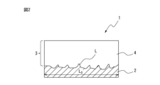
- Fig. 2 is a schematic cross-sectional view of an Al-containing plated steel sheet useful for use in the welded joint according to the embodiment of the present invention, showing the interface length L between the plating layer and the base steel sheet and the length L 0 of the surface of the base steel sheet. Referring to Fig.
- the Al-containing plated steel sheet 1 comprises a base steel sheet 2 and a plating layer 3 formed on the surface of the base steel sheet 2, and the plating layer 3 contains an Fe-Al phase 4.
- the interface length L between the plating layer 3 and the base steel sheet 2 and the corresponding length L 0 of the surface of the base steel sheet 2 satisfy the relationship (L - L 0 ) / L 0 ⁇ 100 ⁇ 3, i.e., the interface length L is 3% or more longer than the length L 0 of the surface of the base steel sheet 2. It can therefore be seen that the interface between the plating layer 3 and the base steel sheet 2 is controlled to have a shape with greater irregularities.
- the interface between the coating layer 3 and the base steel sheet 2 has a shape with greater irregularities as shown in Fig. 2, i.e., when the interface length L between the coating layer 3 and the base steel sheet 2 and the surface length L0 of the base steel sheet 2 satisfy the relationship ( LL0 )/ L0 x 100 ⁇ 3, the alloying rate of the coating layer 3 during spot welding or the alloying rate between the coating layer 3 and a coating layer of the other coated steel sheet becomes faster. More specifically, firstly, as the irregularities at the interface between the coating layer 3 and the base steel sheet 2 become larger, the surface area of the interface portion where alloying proceeds during spot welding becomes larger. It is believed that this makes it possible to increase the alloying rate of the coating layer as a whole.
- the state where the interface between the plating layer 3 and the base steel sheet 2 has greater unevenness is considered to mean that the plating layer 3 has solidified at a stage before the alloying of the plating layer 3 has progressed sufficiently during the manufacture of the Al-containing plated steel sheet 1.
- Fe diffuses from the base steel sheet 2 to the plating layer 3, and the alloying of the plating layer 3 progresses from the interface.
- the other plated steel sheet to be spot-welded is a plated steel sheet containing a relatively large amount of Zn, such as a GA steel sheet
- the Zn component in the plated layer can be sufficiently incorporated into the Fe-Al phase 4 and dissolved in solid solution by alloying with the plated layer 3 during spot welding.
- the welded joint 10 according to the embodiment of the present invention is particularly useful in the automotive field, where spot welding is relatively frequently used.
- the purpose of suppressing or reducing the occurrence of LME cracking during spot welding can be achieved mainly by controlling the area ratio of the Zn-rich phase in the plated layer 18 in the separation portion 17 immediately outside the pressure-welded portion 13 within the range of 0 to 20%.
- the feature of (L - L 0 )/L 0 ⁇ 100 ⁇ 3 for the Al-containing plated steel sheet 1 used in the welded joint 10 is not an essential technical feature for achieving the object of the present invention, but is merely one of the preferable means for reliably controlling the area ratio of the Zn-rich phase in the plating layer 18 in the separation portion 17 immediately outside the pressure-welded portion 13 within the desired range.
- the interface shape between the plating layer 3 and the base steel sheet 2 is preferably 4 or more, and may be, for example, 5 or more, 6 or more, 7 or more, or 8 or more. There is no particular upper limit, but the value of (L- L0 )/ L0 x 100 may be, for example, 30 or less, 20 or less, 15 or less, 12 or less, or 10 or less.
- the present inventors have also studied the manufacture of an Al-containing plated steel sheet 1 useful for use in a welded joint 10 according to an embodiment of the present invention, more specifically, an Al-containing plated steel sheet 1 having an interface shape with greater irregularities between the plated layer 3 and the base steel sheet 2, i.e., an interface shape in which the interface length L between the plated layer 3 and the base steel sheet 2 and the length L 0 of the surface of the base steel sheet 2 satisfy the relationship (L-L 0 )/L 0 ⁇ 100 ⁇ 3.
- the present inventors have found that in order to create such an interface shape itself, it is effective to increase the alloying rate when the plated layer 3 is alloyed.
- the plated layer 3 contains excessive Si and Mg, it may adversely affect the alloying of the plated layer 3, so that the Si and Mg contents in the plated layer 3 must be controlled to 10.0 mass% or less, respectively.
- the alloying rate of the plated layer 3 it is necessary to appropriately control the metal structure of the base steel sheet 2 during the alloying process. More specifically, by making the base steel sheet 2 have a metal structure that is moderately decarburized and contains a larger amount of austenite phase during the alloying treatment, the reaction between the plating layer 3 and the austenite phase in the base steel sheet 2 during the alloying treatment is promoted, that is, the alloying rate can be significantly increased.
- the present inventors have found that it is possible to create a metal structure of the base steel sheet 2 that is moderately decarburized and contains a larger amount of austenite phase by appropriately controlling the annealing step, cooling step, and plating step of the base steel sheet 2. As a result, it is possible to realize an interface shape with greater irregularities such that the interface length L between the plating layer 3 and the base steel sheet 2 and the corresponding surface length L 0 of the base steel sheet 2 satisfy the relationship (L - L 0 ) / L 0 ⁇ 100 ⁇ 3.
- the plating layer of the Al-containing plated steel sheet may or may not contain Zn. However, if the plating layer of the Al-containing plated steel sheet does not contain Zn, the steel sheet adjacent to the Al-containing plated steel sheet must have at least a Zn-containing plating on the surface corresponding to the overlapping surface with the plated steel sheet.
- the plating layer of the Al-containing plated steel sheet has the following chemical composition in the separation area outside the heat-affected zone (i.e., the non-heat-affected zone), which is the same as the initial chemical composition before spot welding.
- the Fe content is set to 55.0% or less.
- the Fe content may be 52.0% or less, 50.0% or less, 48.0% or less, or 45.0% or less.
- Mg is an element effective in improving the corrosion resistance of the plating layer, particularly the chemical conversion treatability.
- the Mg content may be 0%, but in order to obtain such an effect, the Mg content is preferably 0.1% or more.
- the Mg content may be 0.2% or more, 0.3% or more, 0.5% or more, 0.8% or more, 1.0% or more, 1.5% or more, or 2.0% or more.
- the Mg content is set to 10.0% or less.
- the Mg content may be 8.0% or less, 6.0% or less, 5.0% or less, 4.0% or less, 3.0% or less, less than 2.5%, 2.4% or less, or 2.2% or less.
- Si is an element effective in improving the adhesion of the plating layer.
- the Si content may be 0%, but in order to fully obtain such an effect, the Si content is preferably 0.1% or more.
- the Si content may be 0.2% or more, 0.3% or more, 0.5% or more, 0.6% or more, or 0.8% or more.
- the Si content is set to 10.0% or less.
- the Si content may be 8.0% or less, 6.0% or less, 4.0% or less, or 2.0% or less.
- the Si content is preferably 1.0% or less.
- Zn has a sacrificial anticorrosive effect and is an element effective in improving the corrosion resistance of the plating layer.
- the Zn content may be 0%, but in order to fully obtain such an effect, the Zn content is preferably 1.0% or more.
- the Zn content may be 3.0% or more, 5.0% or more, 10.0% or more, 12.0% or more, 15.0% or more, or 18.0% or more.
- the Zn content is preferably 30.0% or less.
- the Zn content may be 28.0% or less, 25.0% or less, 22.0% or less, or 20.0% or less.
- the plating layer may optionally contain Ni: 0-1.000%, Ca: 0-4.000%, Sb: 0-0.500%, Pb: 0-0.500%, Cu: 0-1.000%, Sn: 0-1.000%, Ti: 0-1.000%, Cr: 0-1.000%, Nb: 0-1.000%, Zr: 0-1.000%, Mn: 0-1.000%, Mo: 0-1.000%, Ag: 0 At least one of the following may be contained: 0 to 1.000%, Li: 0 to 1.000%, La: 0 to 0.500%, Ce: 0 to 0.500%, B: 0 to 0.500%, Y: 0 to 0.500%, Sr: 0 to 0.500%, In: 0 to 0.500%, Co: 0 to 0.500%, Bi: 0 to 0.500%, P: 0 to 0.500%, W: 0 to 0.500%, and V: 0 to 0.500%.
- optional elements are not particularly limited, but are preferably 5.000% or less in total.
- the optional elements may be a total of 4.500% or less, 4.000% or less, 3.500% or less, 3.000% or less, 2.500% or less, 2.000% or less, 1.500% or less, 1.000% or less, 0.800% or less, 0.500% or less, 0.100% or less, or 0.050% or less.
- Ni is an element effective for improving the corrosion resistance of the plating layer.
- the Ni content may be 0%, but in order to obtain such an effect, the Ni content is preferably 0.001% or more.
- the Ni content may be 0.003% or more, 0.005% or more, 0.008% or more, 0.010% or more, or 0.020% or more.
- the Ni content is set to 1.000% or less, and may be, for example, 0.500% or less, 0.400% or less, 0.300% or less, 0.100% or less, 0.050% or less, or 0.030% or less.
- Ca is an element effective in ensuring wettability of the plating bath.
- the Ca content may be 0%, but in order to obtain such an effect, the Ca content is preferably 0.001% or more.
- the Ca content may be 0.003% or more, 0.005% or more, or 0.010% or more.
- the Ca content is preferably 4.000% or less.
- the Ca content may be 3.000% or less, 2.000% or less, 1.000% or less, 0.500% or less, 0.300% or less, 0.100% or less, 0.050% or less, or 0.020% or less.
- the contents of Cu, Sn, Ti, Cr, Nb, Zr, Mn, Mo, Ag and Li are preferably 1.000% or less, and may be, for example, 0.800% or less, 0.500% or less, 0.100% or less, 0.050% or less, or 0.020% or less.
- the remainder other than the above elements consists of 20.0% or more Al and impurities.
- the Al content may be, for example, 25.0% or more, 30.0% or more, 35.0% or more, 40.0% or more, 45.0% or more, or 50.0% or more.
- the Al content may be, for example, 80.0% or less, 75.0% or less, 70.0% or less, 65.0% or less, or 60.0% or less.
- Impurities in the plating layer are components that are mixed in due to various factors in the manufacturing process, including raw materials, when the plating layer is manufactured.
- the chemical composition of the plating layer is determined as follows. First, the plating layer is peeled and dissolved from the Al-containing plated steel sheet in the separation part outside the heat-affected zone (i.e., non-heat-affected zone) of the spot welded part using an acid solution containing an inhibitor that suppresses corrosion of the base steel sheet. Next, the chemical composition (average composition) of the plating layer is determined by measuring the obtained acid solution by ICP (inductively coupled plasma) emission spectroscopy.
- the acid species is not particularly limited, and may be any acid that can dissolve the plating layer.
- the chemical composition of the plating layer in this embodiment is the average of measurements performed on three samples.
- the Mg-containing phase refers to a phase having a chemical composition consisting of, in mass %, Mg: 0.5 to 90%, Al: 10 to 99.5%, O: 0 to 70%, Fe: 0 to 3%, and other elements: less than 3%.
- the Mg-containing phase does not include the MgZn2 phase.
- the reaction can be promoted by the action of Mg during chemical conversion treatment, and the adhesion of the chemical conversion coating to the Al-containing plated steel sheet can be improved.
- the higher the surface coverage of the Mg-containing phase the more preferable, and for example, it may be 30% or more, 40% or more, 50% or more, 60% or more, 70% or more, or 80% or more.
- the upper limit is not particularly limited, and the surface coverage of the Mg-containing phase may be 100%.
- the surface coverage of the Mg-containing phase may be 95% or less or 90% or less.
- the Mg content in the plating layer may be appropriately determined according to the desired surface coverage while considering the manufacturing conditions, etc.
- the plating layer contains an Fe-Al phase, and the thickness of the Fe-Al phase is 10 to 200 ⁇ m.
- the Fe-Al phase refers to a phase having a chemical composition consisting of, in mass %, 40 to 70% Fe, 30 to 60% Al, 0 to 20% Zn, and less than 3% other elements (i.e., Fe, Al, and Zn: more than 97% in total).
- the Fe content in the plating layer before spot welding i.e., the Fe content in the plating layer of the non-heat-affected zone, is set to 20.0 mass% or more as described above, while controlling the thickness of the Fe-Al phase contained in the plating layer in the separation zone of the heat-affected zone after spot welding to 10 ⁇ m or more, so that the plating layer can be sufficiently alloyed, thereby improving the corrosion resistance after painting.
- the area ratio of the Zn-rich phase in the plating layer of the separation part in the region 1 mm from the end of the pressure weld is controlled to 0 to 20%.
- the Zn-rich phase refers to a phase containing 60 mass% or more of Zn, and the Zn-rich phase becomes a liquid phase under high temperatures during welding. As described above in relation to FIG.
- the separation part in the region 1 mm from the end of the pressure weld i.e., the separation part in the heat-affected zone located immediately outside the pressure weld
- the area ratio of the Zn-rich phase in the plating layer of the separation part the more preferable it is, and it may be, for example, 18% or less, 15% or less, 12% or less, 10% or less, 8% or less, 5% or less, or 2% or less.
- the area ratio of the Zn-rich phase may be 0.5% or more, or 1% or more.
- a backscattered electron image (BSE image) is obtained by a scanning electron microscope with an electron probe microanalyzer (SEM-EPMA) in a visual field of 80 ⁇ m in the thickness direction and 100 ⁇ m in the direction perpendicular to the thickness direction, and the plating layer in the separation part in the non-heat-affected zone is identified from the BSE image.
- SEM-EPMA electron probe microanalyzer
- the composition of each phase in the identified plating layer is analyzed by point analysis. From the obtained composition, the Mg-containing phase (Mg: 0.5 to 90%, Al: 10 to 99.5%, O: 0 to 70%, Fe: 0 to 3%, and other elements: less than 3%) is identified.
- (L-L 0 )/L 0 ⁇ 100 is determined as follows. First, the mirror-polished sample obtained above is observed with an SEM in a visual field of 80 ⁇ m in the thickness direction and 100 ⁇ m in the direction perpendicular to the thickness direction to obtain a BSE image. The BSE image is measured using the "Analyze" function of the image analysis software "ImageJ" to measure the interface length between the coating layer and the base steel sheet (interface length L between the coating layer and the base steel sheet shown in FIG. 2). The above operation is performed for five visual fields, and the average value is calculated to determine the interface length L.
- (L-L 0 )/L 0 ⁇ 100 is determined from the obtained interface length L and the length L 0 of the surface of the corresponding base steel sheet, i.e., the length of the long side of the observation visual field: 100 ⁇ m.
- the resolution of the SEM image is 2560 ⁇ 1920.
- L 0 is measured using "Find edge" in the "Process” function of the image analysis software "ImageJ”, binarizing with the "Binary” function, and then reading “Perim.” with the "Measure” function in "Analyze”.
- ⁇ M i /L 0 ⁇ 100 surface coverage of the Mg-containing phase
- a BSE image including the end of the pressure-welded part is obtained by SEM-EPMA, and the end of the pressure-welded part of the spot welded part and the region 1 mm from the end of the pressure-welded part toward the separation part (the boundary part between the pressure-welded part and the separation part) are identified from the BSE image.
- elemental analysis is performed on the identified boundary part to identify the area ratio of the Zn-rich phase in the boundary part.
- the Zn-rich phase is a phase with a Zn concentration of 60 mass% or more.
- the field of view of the SEM image is 200 ⁇ m ⁇ 160 ⁇ m, and the same elemental analysis is performed on 10 different points randomly selected from the boundary portion, the area ratio of the Zn-rich phase is calculated in each field of view, and the maximum value among them is determined as the area ratio of the Zn-rich phase.
- the specific measurement conditions of the EPMA in each field of view are as follows. Apparatus: JXA-8500 manufactured by JEOL Ltd.
- the element distribution image of Zn is read into ImageJ, and then binarized in "Make Binary” in “Binary” of “Process” so that the area with a Zn concentration of 60% or more is displayed as black and the area with a Zn concentration of less than 60% is displayed as white.
- the value of "Area fraction” in “Results” is read using "Measure” in “Analyze”, and the value is determined as the area ratio of the Zn-rich phase.
- the thickness of the Fe-Al phase is determined as follows. First, elemental analysis is performed in the same manner at the boundary portion identified above to identify the Fe-Al phase (Fe: 40-70%, Al: 30-60%, Zn: 0-20%, and other elements: less than 3%). Next, the thickness of the identified Fe-Al phase is measured at five different points in the field of view using the "Analyze" function of the image analysis software "ImageJ", and the thickness of the Fe-Al phase is determined by averaging the thicknesses measured at the five points.
- the plating layer may be any plating layer having the above chemical composition, Fe-Al phase and/or Mg-containing phase, but is not particularly limited, and may be, for example, an alloyed hot-dip plating layer.
- the present invention aims to provide a welded joint capable of suppressing or reducing the occurrence of LME cracking during spot welding, and at least one of a plurality of overlapped steel sheets is an Al-containing plated steel sheet having a plating layer on at least the surface corresponding to the overlapping surface, and the plating layer is controlled to have a predetermined chemical composition in a separation part outside the heat-affected zone, and the plating layer in the separation part in a region 1 mm from the end of the pressure-welded part is controlled to have a thickness of the Fe-Al phase within a range of 10 to 200 ⁇ m and an area ratio of the Zn-rich phase within a range of 0 to 20%, thereby achieving the objective.
- the chemical composition of the base steel sheet having the above-mentioned plating layer is not an essential technical feature for achieving the objective of the present invention.
- a preferred chemical composition of the base steel sheet for the Al-containing plated steel sheet useful for use in the welded joint according to the embodiment of the present invention will be described in detail, but these descriptions are intended to be merely examples of the preferred chemical composition of the base steel sheet, and are not intended to limit the present invention to one using a base steel sheet having such a specific chemical composition.
- the base steel plate contains, in mass%, C: 0.01-0.50%, Si: 0.001 to 3.000%, Mn: 0.10-3.00%, Al: 0.0002-2.000%, P: 0.100% or less, S: 0.1000% or less, N: 0.0100% or less, Nb: 0 to 0.15%, Ti: 0 to 0.15%, V: 0 to 0.15%, Mo: 0-1.0%, Cr: 0-1.0%, Cu: 0 to 1.0%, Ni: 0-1.0%, B: 0 to 0.0100%, W: 0-1.000%, Hf: 0 to 0.050%, Mg: 0 to 0.050%, Zr: 0 to 0.050%, Ca: 0-0.010%, REM: 0-0.30%, It is preferable that the chemical composition is Ir: 0 to 1.000%, and the balance: Fe and impurities. Each element will be described in more detail below.
- C is an element that inexpensively increases tensile strength and is an important element for controlling the strength of steel.
- the C content is preferably 0.01% or more.
- the C content may be 0.05% or more, 0.10% or more, 0.15% or more, 0.20% or more, 0.30% or more, or 0.35% or more.
- excessive C content may cause a decrease in elongation.
- the C content is preferably 0.50% or less.
- the C content may be 0.45% or less, or 0.40% or less.
- Al acts as a deoxidizer for steel and is an element that has the effect of improving the soundness of steel.
- the Al content is preferably 0.0002% or more.
- the Al content may be 0.001% or more, 0.010% or more, 0.050% or more, or 0.100% or more.
- the Al content is preferably 2.000% or less.
- the Al content may be 1.500% or less, 1.000% or less, 0.800% or less, or 0.500% or less.
- P 0.100% or less
- P is an element that segregates at grain boundaries and promotes embrittlement of steel. Since the lower the P content, the better, it is ideally 0%. However, excessive reduction in the P content may lead to a significant increase in costs. For this reason, the P content may be 0.0001% or more, or may be 0.001% or more, or 0.005% or more. On the other hand, excessive inclusion of P may lead to embrittlement of steel due to grain boundary segregation as described above. Therefore, the P content is preferably 0.100% or less. The P content may be 0.050% or less, 0.030% or less, or 0.010% or less.
- S is an element that generates nonmetallic inclusions such as MnS in steel, which leads to a decrease in the ductility of steel parts.
- the S content may be 0.0001% or more, 0.0002% or more, 0.0010% or more, or 0.0050% or more.
- the S content is preferably 0.1000% or less.
- the S content may be 0.0500% or less, 0.0200% or less, or 0.0100% or less.
- N is an element that forms coarse nitrides in the steel sheet and reduces the workability of the steel sheet. Since the lower the N content, the more preferable it is, the ideal N content is 0%. However, excessive reduction in the N content may lead to a significant increase in manufacturing costs. For this reason, the N content may be 0.0001% or more, 0.0005% or more, or 0.0010% or more. On the other hand, excessive N content may form coarse nitrides as described above, thereby reducing the workability of the steel sheet. Therefore, the N content is preferably 0.0100% or less. The N content may be 0.0080% or less, or 0.0050% or less.
- the preferred basic chemical composition of the base steel plate is as described above.
- the base steel plate may contain, as necessary, one or more elements selected from the group consisting of Nb: 0-0.15%, Ti: 0-0.15%, V: 0-0.15%, Mo: 0-1.0%, Cr: 0-1.0%, Cu: 0-1.0%, Ni: 0-1.0%, B: 0-0.0100%, W: 0-1.000%, Hf: 0-0.050%, Mg: 0-0.050%, Zr: 0-0.050%, Ca: 0-0.010%, REM: 0-0.30%, and Ir: 0-1.000%, in place of a portion of the remaining Fe.
- Each of these elements may be 0.0001% or more, 0.0005% or more, 0.001% or more, or 0.01% or more.
- the remainder of the base steel plate consists of Fe and impurities.
- Impurities in base steel plate are components that are mixed in due to various factors in the manufacturing process, including raw materials such as ore and scrap, when the base steel plate is industrially manufactured.
- the chemical composition of the base steel plate may be measured by a general analytical method.
- the chemical composition of the base steel plate may be measured by first removing the plating layer by mechanical grinding, and then using ICP-AES (Inductively Coupled Plasma-Atomic Emission Spectrometry) on the cutting chips in accordance with JIS G 1201:2014.
- ICP-AES Inductively Coupled Plasma-Atomic Emission Spectrometry
- a 35 mm square test piece may be obtained from the vicinity of the 1/2 position of the plate thickness of the base steel plate, and the composition may be identified by measuring it under conditions based on a calibration curve created in advance using a Shimadzu ICPS-8100 or similar (measuring device).
- C and S which cannot be measured by ICP-AES, may be measured using the combustion-infrared absorption method, N may be measured using the inert gas fusion-thermal conductivity method, and O may be measured using the inert gas fusion-non-dispersive infrared absorption method.
- the thickness of the base steel plate is not particularly limited, and may be, for example, 0.2 mm or more, 0.3 mm or more, 0.6 mm or more, 1.0 mm or more, or 2.0 mm or more. Similarly, the thickness of the base steel plate may be, for example, 6.0 mm or less, 5.0 mm or less, or 4.0 mm or less.
- any appropriate steel sheet or plated steel sheet can be used as the other steel sheet other than the above-described Al-containing plated steel sheet.
- the plated steel sheet may contain Zn or may not contain Zn.
- the plating layer of the above-mentioned Al-containing plated steel sheet does not contain Zn
- the steel sheet adjacent to the Al-containing plated steel sheet needs to have at least a Zn-containing plating on the surface corresponding to the overlapping surface with the Al-containing plated steel sheet.
- an appropriate steel sheet or plated steel sheet may be appropriately selected according to the application and desired characteristics of the welded joint, for example, the desired joint strength, etc.
- the Al-containing plated steel sheet can be manufactured, for example, by carrying out a casting process in which molten steel with an adjusted chemical composition is cast to form a steel slab, a hot rolling process in which the steel slab is hot rolled to obtain a hot rolled steel sheet, a coiling process in which the hot rolled steel sheet is coiled, a cold rolling process in which the coiled hot rolled steel sheet is cold rolled to obtain a cold rolled steel sheet, a pretreatment process, an annealing process in which the pretreated cold rolled steel sheet is annealed, a cooling process in which the annealed cold rolled steel sheet is cooled, and a plating process in which a plating layer is formed on the obtained base steel sheet.
- the cold rolling process may be carried out directly after pickling without coiling after the hot rolling process. Each process will be described in detail below.
- a predetermined pretreatment process may be performed before annealing the cold-rolled steel sheet.
- a pretreatment process may include a degreasing process.
- the degreasing process may include passing an electric current through the cold-rolled steel sheet in a solution having a pH of 8.0 or more (electrolysis process).
- the current density during the current passing may be 1.0 to 8.0 A/ dm2 , and the current passing time may be 5 to 10 seconds.
- the annealing step includes heating the cold-rolled steel sheet to a temperature of 780 to 900°C in an atmosphere with a dew point of -10 to 10°C and holding the temperature for 10 to 300 seconds.
- the annealing step includes heating the cold-rolled steel sheet to a temperature of 780 to 900°C in an atmosphere with a dew point of -10 to 10°C and holding the temperature for 10 to 300 seconds.
- the surface layer of the cold-rolled steel sheet can be appropriately decarburized.
- the reaction between the plating layer and the base steel sheet is promoted during the alloying treatment in the subsequent plating step, that is, it is possible to increase the alloying rate.
- the formation of a Zn-rich phase can be suppressed or reduced to within a range of 0 to 20% in terms of area ratio, thereby making it possible to significantly suppress or reduce the occurrence of LME cracking around the pressure welded portion.
- the dew point is lower than -10°C, the annealing temperature is lower than 780°C, and/or the annealing time is shorter than 10 seconds, the decarburization of the surface layer of the cold-rolled steel sheet is insufficient, and a sufficient alloying rate cannot be obtained during the alloying treatment of the coating layer. As a result, it becomes impossible to realize an interface shape that satisfies the relationship (LL 0 )/L 0 ⁇ 100 ⁇ 3 between the coating layer and the base steel sheet.
- the atmosphere in the annealing step may be a reducing atmosphere, more specifically a reducing atmosphere containing nitrogen and hydrogen, for example, a reducing atmosphere of 1 to 10% hydrogen (for example, 3% hydrogen and the balance of nitrogen).
- the cold-rolled steel sheet whose surface layer has been decarburized in the annealing process needs to be appropriately cooled in the subsequent cooling process in order to obtain a desired surface layer structure.
- the cooling process includes cooling from the heating temperature (annealing temperature) in the annealing process to a controlled temperature of 500 to 750° C. at an average cooling rate of 5° C./s or more. This will be described in detail below.
- the annealed cold-rolled steel sheet is then cooled to a temperature below 500°C, for example, to a temperature of about 200°C, and then reheated to be plated.
- the metal structure that has been austenitized in the annealing process is transformed into a structure such as bainite or martensite. Therefore, in the subsequent plating process, the metal structure such as bainite or martensite is alloyed with the plating layer.
- the metal structure of the cold-rolled steel sheet can be maintained in a state containing a larger amount of austenite phase by cooling from the annealing temperature to a controlled temperature of 500 to 750° C. at an average cooling rate of 5° C./s or more.
- a controlled temperature 500 to 750° C. at an average cooling rate of 5° C./s or more.
- the average cooling rate from the annealing temperature to the control temperature of 500 to 750°C is less than 5°C/s, the transformation to ferrite becomes significant, and similarly, it becomes impossible to achieve a sufficient alloying rate in the subsequent coating process. As a result, in either case, it becomes impossible to realize an interface shape that satisfies the relationship (L-L 0 )/L 0 ⁇ 100 ⁇ 3 between the coating layer and the base steel sheet.
- the control temperature exceeds 750°C, the temperature becomes higher than the temperature suitable for the subsequent coating process, and the desired coating layer may not be obtained.
- the average cooling rate is preferably, for example, 30° C./s or less.
- a plating layer is formed on at least one, preferably both, surfaces of the cold-rolled steel sheet (base steel sheet). More specifically, the plating step is performed by immersing the cold-rolled steel sheet cooled to the above-mentioned controlled temperature in a plating bath (plating bath temperature: for example, 680 to 750°C) having a predetermined chemical composition while maintaining a state in which the austenite phase is contained in a larger amount, and then heat treating it for 0.5 to 20 seconds at an alloying temperature of 680 to 750°C.
- a plating bath temperature for example, 680 to 750°C
- the plating layer can be appropriately alloyed so that the thickness of the Fe-Al phase becomes a desired thickness, and a sufficient alloying speed can be realized based on the combination of decarburization and austenite phase.
- a sufficient alloying speed can be realized based on the combination of decarburization and austenite phase.
- the Zn component in the plating layer of another Zn-containing plated steel sheet can be sufficiently incorporated into the plating layer of the Al-containing plated steel sheet under the high temperature during spot welding to form a solid solution, and as a result, the formation of a Zn-rich phase can be suppressed or reduced to a range of 0 to 20% in terms of area ratio in the plating layer of the separation portion in a region 1 mm from the end of the pressure welded portion of the finally obtained welded joint.
- the plating layer solidifies in a state where the alloying is insufficient, the Fe content in the plating layer decreases, and/or the desired Fe-Al phase thickness cannot be obtained in the separation part immediately outside the pressure welded part during spot welding. As a result, the corrosion resistance after painting of the Al-containing plated steel sheet decreases. Also, if the alloying treatment time is shorter than 0.5 seconds, the alloying of the plating layer is insufficient, and the interface between the plating layer and the base steel sheet cannot be made into an uneven shape, and/or the desired Fe-Al phase thickness cannot be obtained in the separation part immediately outside the pressure welded part during spot welding.
- the alloying treatment time is preferably 5 to 20 seconds.
- the base steel sheet to which the plating layer is attached is cooled to obtain an Al-containing plated steel sheet.
- the cooling after plating is not particularly limited and can be performed under any appropriate conditions known to those skilled in the art.
- the cooling after plating can be performed at an average cooling rate of 10°C/s or more.
- the cooling stop temperature is also not particularly limited and may be appropriately set within the range of, for example, 100 to 350°C.
- an Al-containing plated steel sheet having a plating layer in which the chemical composition of the plating layer is optimized within a predetermined range, i.e., by mass %, Fe: 20.0 to 55.0%, Mg: 0 to 10.0%, Si: 0 to 10.0%, and Al: 20.0% or more, and the interface shape between the plating layer and the base steel sheet is controlled to satisfy the relationship of (L- L0 )/ L0 x 100 ⁇ 3.
- the Zn component in the plating layer of the other Zn-containing plated steel sheet can be sufficiently incorporated into the plating layer of the Al-containing plated steel sheet at the high temperature during spot welding to form a solid solution.
- the formation of a Zn-rich phase can be suppressed or reduced to within a range of 0 to 20% in terms of area ratio, thereby making it possible to significantly suppress or reduce the occurrence of LME cracking around the pressure welded portion.
- the welded joint according to the embodiment of the present invention can be manufactured by forming a nugget and a pressure-welded portion around the nugget by applying pressure to the plurality of steel sheets stacked together as described above using a pair of opposing electrodes while passing current between the electrodes under normal conditions.
- the spot welding conditions may be any suitable conditions known to those skilled in the art.
- the welding electrode may be a dome radius type welding electrode having a tip diameter of 6 to 8 mm
- the pressure may be 1.5 to 6.0 kN
- the current flow time may be 0.1 to 1.0 s (5 to 50 cycles, power supply frequency 50 Hz)
- the current may be 4 to 15 kA
- the impact angle (the angle between the axial direction of the electrode and the direction perpendicular to the surface of the steel sheet) may be 0 to 10°.
- the area ratio of the Zn-rich phase in the plating layer in the separation area just outside the pressure weld can be controlled within a desired range, and in connection with this, it is possible to suppress or reduce the penetration of molten Zn into the steel sheet during spot welding. Therefore, with such a welded joint, it is possible to achieve better LME resistance compared to the use of conventional plated steel sheets. This can contribute to industrial development through longer life in the automotive and construction fields.
- Al-containing plated steel sheets were manufactured under various conditions, and the LME resistance of welded joints obtained by spot welding the manufactured Al-containing plated steel sheets was investigated.
- molten steel was cast by a continuous casting method to form a steel slab having a chemical composition consisting of, in mass%, C: 0.20%, Si: 0.012%, Mn: 1.30%, Al: 0.030%, P: 0.005%, S: 0.0020%, and N: 0.0030%, with the balance being Fe and impurities.
- the steel slab was once cooled, then reheated to 1200 ° C. and hot rolled, and then coiled at a temperature of 600 ° C. or less.
- the hot rolling was performed by performing rough rolling and finish rolling, the finish rolling end temperature was 900 to 1050 ° C., and the rolling reduction ratio of the finish rolling was 30%.
- the obtained hot-rolled steel sheet was pickled, and then cold rolled at a rolling reduction ratio of 50% to obtain a cold-rolled steel sheet having a sheet thickness of 1.6 mm.
- the obtained cold-rolled steel sheet was subjected to a pretreatment (degreasing treatment) in which a current was passed through the sheet in a solution of pH 9.2 at a current density of 5.0 A/dm 2 for 8 seconds.
- each cold-rolled steel sheet was cut into a size of 100 mm x 200 mm, and then annealed under the conditions shown in Table 1 (annealing atmosphere: hydrogen 3% and nitrogen balance).
- the cut steel sheet sample was cooled from the annealing temperature to the control temperature at the average cooling rate shown in Table 1, and then immersed in a hot-dip galvanizing bath (galvanizing bath temperature: 680 to 750 ° C) having a predetermined bath composition, and alloyed under the conditions shown in Table 1.
- the coating weight was adjusted by pulling up the steel sheet sample after immersion in the galvanizing bath and wiping with N2 gas.
- the base steel sheet to which the coating layer was attached was cooled at an average cooling rate of 10 ° C / s or more to obtain an Al-containing coated steel sheet (first steel sheet in Table 1) in which a coating layer was formed on both sides of the base steel sheet.
- a plated steel sheet sample having a size of 100 ⁇ 100 mm was subjected to spot welding. Two pieces cut to a size of 50 mm ⁇ 100 mm were prepared, and these two plated steel sheet samples were spot-welded using a dome radius type welding electrode having a tip diameter of 8 mm at an impact angle of 2°, a pressure of 4.0 kN, a current flow time of 0.8 seconds, and a current flow current of 12 kA to produce a welded joint. At least one of the two plated steel sheet samples was a Zn-containing plated steel sheet. More specifically, as shown in Table 1, a conventional galvannealed (GA) steel sheet was used as the second steel sheet except for Examples 2 and 3, and the same type of Al-Zn-containing plated steel sheet was used as the first and second steel sheets in Examples 2 and 3.
- GA galvannealed
- the chemical conversion treatability was evaluated as follows. First, a 50 mm x 100 mm sample (corresponding to a non-heat-affected portion) of the produced Al-containing plated steel sheet was subjected to a Zn phosphate treatment (SD5350 system: standard manufactured by Nippon Paint Industrial Coating Co., Ltd.) to form a chemical conversion coating. Next, the sample surface was observed with a secondary electron image of an SEM, and the area ratio of the portion where the chemical conversion coating was not formed, generally called "blank", was measured. The chemical conversion treatability of the Al-containing plated steel sheet was evaluated according to the area ratio of blank, using the following evaluation criteria. AA: Blank area rate 0-5% A: Scale area ratio: 5% to 15% -: Blank area ratio over 15%
- Comparative Example 31 the annealing temperature was low, so it is considered that the decarburization of the surface layer of the cold-rolled steel sheet was insufficient, and a sufficient alloying rate could not be obtained during the alloying treatment of the plating layer.
- the value of (L-L 0 )/L 0 ⁇ 100 was less than 3, and the area ratio of the Zn-rich phase in the plating layer in the separation part directly outside the pressure-welded part exceeded 20%, and the LME resistance was reduced.
- the annealing time was short, so decarburization of the surface layer of the cold-rolled steel sheet was insufficient, and it is considered that a sufficient alloying rate could not be obtained during the alloying treatment of the coating layer.
- the value of (L-L 0 )/L 0 ⁇ 100 was less than 3, and the area ratio of the Zn-rich phase in the plating layer in the separation part immediately outside the pressure-welded part exceeded 20%, so that the LME resistance was deteriorated.
- the alloying treatment time of the plating layer was short, so that the alloying of the plating layer was insufficient, and the interface between the plating layer and the base steel sheet could not be made into an uneven shape, that is, the value of (L-L 0 )/L 0 ⁇ 100 was less than 3, and furthermore, the desired Fe-Al phase thickness could not be obtained.
- the chemical composition of the plating layer in the separation area of the non-heat-affected zone was optimized within a prescribed range, i.e., by mass %, Fe: 20.0-55.0%, Mg: 0-10.0%, Si: 0-10.0%, and Al: 20.0% or more, and the thickness of the Fe-Al phase in the separation area immediately outside the pressure weld was controlled to 10-200 ⁇ m and the area ratio of the Zn-rich phase to within a range of 0-20%, thereby reliably suppressing or reducing LME cracking.
Landscapes
- Chemical & Material Sciences (AREA)
- Engineering & Computer Science (AREA)
- Mechanical Engineering (AREA)
- Materials Engineering (AREA)
- Metallurgy (AREA)
- Organic Chemistry (AREA)
- Chemical Kinetics & Catalysis (AREA)
- Coating With Molten Metal (AREA)
Priority Applications (1)
| Application Number | Priority Date | Filing Date | Title |
|---|---|---|---|
| JP2025555009A JP7817666B2 (ja) | 2023-11-01 | 2024-10-30 | 溶接継手 |
Applications Claiming Priority (2)
| Application Number | Priority Date | Filing Date | Title |
|---|---|---|---|
| JP2023187884 | 2023-11-01 | ||
| JP2023-187884 | 2023-11-01 |
Publications (1)
| Publication Number | Publication Date |
|---|---|
| WO2025095006A1 true WO2025095006A1 (ja) | 2025-05-08 |
Family
ID=95582382
Family Applications (1)
| Application Number | Title | Priority Date | Filing Date |
|---|---|---|---|
| PCT/JP2024/038724 Pending WO2025095006A1 (ja) | 2023-11-01 | 2024-10-30 | 溶接継手 |
Country Status (2)
| Country | Link |
|---|---|
| JP (1) | JP7817666B2 (https=) |
| WO (1) | WO2025095006A1 (https=) |
Citations (5)
| Publication number | Priority date | Publication date | Assignee | Title |
|---|---|---|---|---|
| JPH0681099A (ja) * | 1992-08-31 | 1994-03-22 | Sumitomo Metal Ind Ltd | 合金化溶融亜鉛めっき鋼板 |
| JP2015003340A (ja) * | 2014-06-30 | 2015-01-08 | 日新製鋼株式会社 | 耐食性に優れる自動車シャシ部材およびその製造法 |
| JP2016166414A (ja) * | 2015-03-02 | 2016-09-15 | Jfe鋼板株式会社 | 溶融Al−Zn−Mg−Siめっき鋼板とその製造方法 |
| WO2022085287A1 (ja) * | 2020-10-20 | 2022-04-28 | 日本製鉄株式会社 | めっき鋼板 |
| WO2023176100A1 (ja) * | 2022-03-14 | 2023-09-21 | Jfeスチール株式会社 | 熱間プレス部材および熱間プレス用鋼板、ならびにそれらの製造方法 |
Family Cites Families (3)
| Publication number | Priority date | Publication date | Assignee | Title |
|---|---|---|---|---|
| KR102648242B1 (ko) | 2018-12-19 | 2024-03-18 | 주식회사 포스코 | 전기 저항 점용접성이 우수한 고강도 아연도금강판 및 그 제조방법 |
| KR102453006B1 (ko) | 2020-12-18 | 2022-10-12 | 주식회사 포스코 | 도금성이 우수한 고강도 용융아연도금강판 및 그 제조방법 |
| EP4276215A4 (en) | 2021-01-08 | 2024-07-03 | Nippon Steel Corporation | WELDED JOINT AND VEHICLE COMPONENT |
-
2024
- 2024-10-30 WO PCT/JP2024/038724 patent/WO2025095006A1/ja active Pending
- 2024-10-30 JP JP2025555009A patent/JP7817666B2/ja active Active
Patent Citations (5)
| Publication number | Priority date | Publication date | Assignee | Title |
|---|---|---|---|---|
| JPH0681099A (ja) * | 1992-08-31 | 1994-03-22 | Sumitomo Metal Ind Ltd | 合金化溶融亜鉛めっき鋼板 |
| JP2015003340A (ja) * | 2014-06-30 | 2015-01-08 | 日新製鋼株式会社 | 耐食性に優れる自動車シャシ部材およびその製造法 |
| JP2016166414A (ja) * | 2015-03-02 | 2016-09-15 | Jfe鋼板株式会社 | 溶融Al−Zn−Mg−Siめっき鋼板とその製造方法 |
| WO2022085287A1 (ja) * | 2020-10-20 | 2022-04-28 | 日本製鉄株式会社 | めっき鋼板 |
| WO2023176100A1 (ja) * | 2022-03-14 | 2023-09-21 | Jfeスチール株式会社 | 熱間プレス部材および熱間プレス用鋼板、ならびにそれらの製造方法 |
Also Published As
| Publication number | Publication date |
|---|---|
| JP7817666B2 (ja) | 2026-02-19 |
| JPWO2025095006A1 (https=) | 2025-05-08 |
Similar Documents
| Publication | Publication Date | Title |
|---|---|---|
| JP6777173B2 (ja) | スポット溶接用高強度亜鉛めっき鋼板 | |
| TWI500780B (zh) | 熔融鍍鋅鋼板及其製造方法 | |
| US12037665B2 (en) | Spot welded member | |
| KR101707984B1 (ko) | 용융 Al-Zn계 도금 강판 | |
| KR102842317B1 (ko) | 강판, 부재 및 그들의 제조 방법 | |
| JP7137492B2 (ja) | 合金化溶融亜鉛めっき鋼板、及び合金化溶融亜鉛めっき鋼板の製造方法 | |
| JP5392116B2 (ja) | 合金化溶融亜鉛めっき鋼板およびその製造方法 | |
| JP7311041B2 (ja) | Fe系電気めっき鋼板,電着塗装鋼板,自動車部品,電着塗装鋼板の製造方法,及びFe系電気めっき鋼板の製造方法 | |
| JP7587195B2 (ja) | 溶接継手 | |
| KR102933688B1 (ko) | 강 용접 부재 | |
| KR102065230B1 (ko) | 점 용접성이 우수한 초고강도 고망간 아연도금강판 및 그의 제조방법 | |
| JP4601502B2 (ja) | 高強度電縫鋼管の製造方法 | |
| JP7243949B1 (ja) | 熱間プレス部材 | |
| JP7144710B1 (ja) | 亜鉛系めっき鋼板および冷延鋼板 | |
| JP7817666B2 (ja) | 溶接継手 | |
| KR102904903B1 (ko) | 열간 프레스 부재 및 열간 프레스용 강판 그리고 열간 프레스 부재의 제조 방법 | |
| WO2024150820A1 (ja) | 溶接継手 | |
| JP7791500B2 (ja) | めっき鋼板 | |
| JP7791459B2 (ja) | 溶接継手 | |
| JP7791458B2 (ja) | めっき鋼板 | |
| KR20260061283A (ko) | 도금 강판 | |
| US20260103780A1 (en) | Hot pressed member and steel sheet for hot press forming | |
| WO2025263630A1 (ja) | 鋼部材 | |
| WO2023074115A1 (ja) | 熱間プレス部材 | |
| WO2025263623A1 (ja) | 鋼部材 |
Legal Events
| Date | Code | Title | Description |
|---|---|---|---|
| 121 | Ep: the epo has been informed by wipo that ep was designated in this application |
Ref document number: 24885773 Country of ref document: EP Kind code of ref document: A1 |
|
| ENP | Entry into the national phase |
Ref document number: 2025555009 Country of ref document: JP Kind code of ref document: A |
|
| WWE | Wipo information: entry into national phase |
Ref document number: 2025555009 Country of ref document: JP |