WO2025088713A1 - クラッチ装置 - Google Patents
クラッチ装置 Download PDFInfo
- Publication number
- WO2025088713A1 WO2025088713A1 PCT/JP2023/038454 JP2023038454W WO2025088713A1 WO 2025088713 A1 WO2025088713 A1 WO 2025088713A1 JP 2023038454 W JP2023038454 W JP 2023038454W WO 2025088713 A1 WO2025088713 A1 WO 2025088713A1
- Authority
- WO
- WIPO (PCT)
- Prior art keywords
- clutch
- plate
- cam
- center
- element body
- Prior art date
- Legal status (The legal status is an assumption and is not a legal conclusion. Google has not performed a legal analysis and makes no representation as to the accuracy of the status listed.)
- Pending
Links
Images


Classifications
-
- F—MECHANICAL ENGINEERING; LIGHTING; HEATING; WEAPONS; BLASTING
- F16—ENGINEERING ELEMENTS AND UNITS; GENERAL MEASURES FOR PRODUCING AND MAINTAINING EFFECTIVE FUNCTIONING OF MACHINES OR INSTALLATIONS; THERMAL INSULATION IN GENERAL
- F16D—COUPLINGS FOR TRANSMITTING ROTATION; CLUTCHES; BRAKES
- F16D13/00—Friction clutches
- F16D13/22—Friction clutches with axially-movable clutching members
- F16D13/38—Friction clutches with axially-movable clutching members with flat clutching surfaces, e.g. discs
- F16D13/52—Clutches with multiple lamellae ; Clutches in which three or more axially moveable members are fixed alternately to the shafts to be coupled and are pressed from one side towards an axially-located member
-
- F—MECHANICAL ENGINEERING; LIGHTING; HEATING; WEAPONS; BLASTING
- F16—ENGINEERING ELEMENTS AND UNITS; GENERAL MEASURES FOR PRODUCING AND MAINTAINING EFFECTIVE FUNCTIONING OF MACHINES OR INSTALLATIONS; THERMAL INSULATION IN GENERAL
- F16D—COUPLINGS FOR TRANSMITTING ROTATION; CLUTCHES; BRAKES
- F16D43/00—Automatic clutches
- F16D43/02—Automatic clutches actuated entirely mechanically
- F16D43/04—Automatic clutches actuated entirely mechanically controlled by angular speed
Definitions
- the present invention relates to a clutch device that is incorporated into the engine of a motorcycle or the like, and in particular to a new clutch device that can optimize the clutch transmission conditions during acceleration and deceleration.
- the following type of clutch device is commonly used for manually operated motorcycles etc. That is, the clutch device is incorporated in a transmission system that transmits the rotational power of the engine to the transmission side, and is used to cut off and connect (disconnect) the transmitted power.
- JP 2011-33106 A Patent No. 7203271
- the present invention was made in consideration of this background, and the technical objective was to develop a new clutch device that could achieve the above-mentioned effects by changing some parts while still allowing the reuse of many of the components in existing clutch devices.
- the clutch device is A clutch device that is incorporated in a transmission system that transmits the rotational power of an engine to a transmission and cuts off and connects the rotational power, the clutch device comprising: a cylindrical basket-shaped clutch outer to which rotational power is input; a clutch center that is disposed concentrically with the clutch outer within the clutch outer and is fixed to the input shaft of the transmission in a state where it is not subject to rotational constraint by the clutch outer; a clutch element body including a plurality of clutch plates and friction plates arranged alternately and interposed between the clutch outer and the clutch center, and which is engaged in a rotational direction by selecting either the clutch outer or the clutch center; a clutch spring that presses the clutch plate and the friction plate in the clutch element body to frictionally join them; a pressure plate that applies the pressing force of the clutch spring to the clutch element body; a release mechanism that releases the pressure applied to the clutch element body to release the frictional connection between the clutch plate and the friction plate; Furthermore, a connection optimization mechanism is provided between the clutch
- the pressure plate has a plate pressing ring portion formed on the outer periphery of the pressure disk portion to receive the clutch element body,
- the plate receiving flange portion of the clutch center and the plate pressing ring portion of the pressure plate are disposed opposite to each other with the clutch element body sandwiched therebetween,
- a cam mechanism is formed by providing a mating element, which is a cam protrusion having an inclined cam surface and a cam groove, at a contact portion between an end of the clutch plate engagement boss in the clutch center and a pressure disk portion in the pressure plate, and
- This cam mechanism is located on the outer periphery of the clutch spring arrangement circle, and when positive or negative torque is generated in the transmission system, this cam mechanism displaces the space between the plate receiving flange portion of the clutch center and the plate pressing ring portion of the pressure plate either widening or narrowing, thereby changing the pressure contact state of the clutch element body to either strong or weak, thereby optimizing the clutch connection state.
- the clutch device has, in addition to the requirements of claim 1,
- the cam mechanism includes a cam groove formed on the clutch center side and a cam protrusion formed on the pressure plate side, the cam groove is formed in a corner portion on the outer circumferential side facing the pressure plate side in the clutch plate engagement boss of the clutch center, and includes an assist cam groove surface that strengthens the rotational transmission force and a slipper cam groove surface that weakens the rotational transmission force,
- the cam protrusion is provided on the pressure plate side at a position corresponding to the cam groove, and is characterized in that it has an assist cam protrusion surface that strengthens the rotational transmission force and a slipper cam protrusion surface that weakens the rotational transmission force.
- the clutch device has, in addition to the requirements of claim 2,
- the cam projection formed on the pressure plate side is formed so as to relatively project toward the clutch center side by forming an assist cam projection and a slipper cam projection in an inclined state so as to face each other on two sides with respect to the plate pressing ring portion capable of pressing the clutch element body, and the end face of the cam projection on the clutch center side is formed so as to be on the same plane as the plate pressing ring portion,
- the cam groove formed on the clutch center side is characterized in that it is formed in an inclined state so that the assist cam groove surface and the slipper cam groove surface are carved in two opposing faces relative to the hub retaining disk portion that abuts against the pressure plate.
- connection optimization mechanism is configured such that the cam mechanism is located on the outer periphery of the clutch spring arrangement circle, so that the friction load between the cam groove surface and the cam protrusion surface that constitute the cam mechanism is kept small, while a relatively large torque is obtained during assist and slipper operation, resulting in a smooth assist and slipper state.
- the cam groove surface of the cam mechanism is configured on the clutch center side, and the cam protrusion surface of the cam mechanism is configured on the pressure plate side, so a specific configuration of the cam groove surface and the cam protrusion surface can be realized.
- the cam protrusion formed on the pressure plate side is formed so as not to protrude from the plate pushing ring portion, and the cam groove formed on the clutch center side is also formed so as not to protrude from the hub holding disc portion. Therefore, the cam mechanism does not hinder the movement of the clutch element body, ensuring smooth operation of the clutch element body.
- the processing required to form the cam mechanism is easy, and it is possible to upgrade current clutches (clutches that do not have a cam mechanism) with minimal part changes, making it easy to improve on current clutches.
- FIG. 1A is a front view showing a pressure plate
- FIG. 1B is a rear view showing the pressure plate
- FIG. 1A is a front view
- FIG. 1B is a side view
- FIG. 1C is a rear view
- FIG. 1D is a perspective view seen from the front side
- FIG. 1E is a perspective view seen from the rear side, showing the clutch center.
- FIG. 1A is a front view showing the pressure plate and the clutch center in an assembled state
- FIG. 1B is a rear view
- FIG. 1C is a perspective view seen from the direction A in FIG. 1B
- FIG. 1D is a perspective view cut along line B-B in FIG.
- FIG. 1A is a front view showing the components of the clutch device in an assembled state
- FIG. 1A is a front view showing the components of the clutch device in an assembled state
- FIG. 1A is a front view showing the components of the clutch device in an assembled state
- FIG. 1A is a front view showing the
- FIG. 1B is a cross-sectional view taken along line CC of FIG. 1A
- FIG. 1C is a projection view taken along line D-D of FIG. 1A
- FIG. 1D is an oblique view taken along line D-D of FIG. 1A
- FIG. 1E is an explanatory diagram showing the assist and slipper functions.
- 1A is a cross-sectional view showing the components of the clutch device in an assembled state (clutch engaged state)
- FIG. 1B is a cross-sectional view showing a state in which a release mechanism is actuated from this state.
- 1A and 1B are two perspective views showing members provided on the outside of a clutch device.
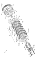
- the clutch device C of the present invention is incorporated in a transmission path that transmits rotational power from an engine to a transmission in a motorcycle, and has a major feature in that it includes a connection optimization mechanism 7 that optimizes power transmission.
- a connection optimization mechanism 7 that optimizes power transmission.
- the clutch device C is incorporated in a transmission system that transmits the rotational power of the engine side to the transmission side, and is a device that performs connection and disconnection (disconnection/connection) of the transmitted power.
- connection state in which the rotational power of the engine side is transmitted to the transmission side can be such that the rotational power of the engine side is not completely transmitted to the transmission side, but the transmission members are rubbed against each other by operating the clutch device C, and the transmitted power is weakened and transmitted, which is a so-called "half-clutch” state.
- "connection and disconnection of the transmitted power” in this specification includes not only the complete disconnection or connection of the transmitted power, but also the half-clutch state in which the rotational power of the engine is weakened and transmitted to the transmission side.
- the clutch device C comprises a cylindrical basket-shaped clutch outer 1 to which the rotational power of the engine is input, and a clutch center 2 arranged concentrically with the clutch outer 1 within the clutch outer 1 and fixed to the transmission input shaft 9 without being subject to rotational constraints of the clutch outer 1. Furthermore, a clutch element body 3 is interposed between the clutch outer 1 and the clutch center 2, and this clutch element body 3 is provided with a plurality of clutch plates 35 and friction plates 31 that selectively engage with either the clutch outer 1 or the clutch center 2 in the rotational direction, and the clutch plates 35 and the friction plates 31 are arranged so as to overlap alternately in the assembled state.
- the friction plates 31 are configured to engage with the clutch outer 1 and rotate together, and the clutch plates 35 are configured to engage with the clutch center 2 and rotate together.
- the clutch plates 35 are arranged between each of the six friction plates 31, for a total of five clutch plates 35.
- the clutch plates 35 and friction plates 31 in the clutch element body 3 are brought into a pressure contact state by the force of clutch springs S (four in this case) and are configured to be frictionally joined to each other (so-called clutch engaged state).
- a pressure plate 5 for applying the pressing force of the clutch springs S to the clutch element body 3 is provided inside the clutch outer 1. That is, the clutch plates 35 and the friction plates 31 are provided between the pressure plate 5 (plate pressing ring portion 53 described later) and the clutch center 2 (plate receiving flange portion 24), and are pressed so as to be in close contact with the clutch plates 35 and the friction plates 31 by the biasing force of the clutch spring S.
- a connection optimization mechanism 7 is provided between the clutch center 2 and the pressure plate 5 for optimizing the connection state of the clutch element body 3 in either or both of the forward and reverse directions of torque transmission to the clutch element body 3.
- the clutch device C pushes or pulls in the pressure plate 5 by means of a release mechanism 6 when performing a connecting/disconnecting operation, and the following explanation based on the illustrated embodiment employs a so-called side-push type clutch device C.
- the present invention is also applicable to other types such as a side-pull type and a center-push type.
- the clutch outer 1 is a so-called cylindrical basket-shaped member, which is sometimes called a clutch basket, for example, and is formed by combining a driven gear 11 and a clutch basket 12, and the two are configured to rotate together.
- the driven gear 11 receives rotational power from the engine, and in practice, a shock absorbing mechanism such as a rubber bush may be installed between the driven gear 11 and the clutch basket 12 .
- the clutch basket 12 is one of the members that directly perform the clutch action, and has a large number of external tooth receiving slits 13 formed on the outer circumferential surface of the basket for receiving friction plates 31 which are one of the components of the clutch element body 3 described below.
- the formation of the external tooth receiving slits 13 results in a large number of comb-like torque receiving pawls 14 being arranged on the circumferential surface of the clutch basket 12, and the side end surfaces of these torque receiving pawls 14 become torque receiving surfaces 14a.
- a center bush 15 or a center bearing is assembled in the center of the clutch basket 12 and the driven gear 11 integral therewith.
- the clutch center 2 incorporated in such a clutch outer 1 has a bearing hub 21 formed in the center, as shown in Figure 3 as an example, and an internal spline 21a is formed on the inside of this bearing hub 21 so as to be spline-engaged with the transmission input shaft 9 side.
- a cylindrical clutch plate engagement boss 23 is formed integrally with the clutch center 2 from the outer circumferential end side of the hub holding disk portion 22.
- a plate receiving flange portion 24 is formed on the other end (the end facing the pressure plate 5) of this clutch plate engagement boss 23, protruding toward the outer circumferential side.
- a large number of clutch plate engagement splines 25 are formed on the outer periphery of the clutch plate engagement boss 23 and extend along the axial direction.
- the "axial direction” described in this specification refers to the axial direction of the transmission input shaft 9, in other words, the assembly direction of the clutch plates 35 and the friction plates 31, which are assembled alternately.
- internal tooth receiving grooves 26 for receiving internal plate teeth 36 of clutch plate 35 in clutch element body 3 are formed in the relatively recessed portions.
- the clutch center 2 is formed with a spring guide hole 27 for receiving a spring guide 55 in the pressure plate 5, which will be described later.
- the spring guide hole 27 is opened in four places (so-called equidistant), and a spring receiving seat 28 is formed to surround the spring guide hole 27.
- the clutch element body 3 is composed of an alternating combination of friction plates 31 and clutch plates 35, and is configured so that the clutch is in an engaged state when the two are pressed against each other by the force of the clutch spring S (see Figure 1).
- the friction plate 31 is an annular flat plate member, and since the friction plate 31 rotates together with the clutch outer 1 as already described, a plurality of plate external teeth 32 (the same number as the external tooth receiving slits 13 of the clutch outer 1) are formed so as to protrude toward the outer periphery and are structured to engage with the external tooth receiving slits 13.
- the clutch outer 1 and the friction plate 31 are configured to always rotate almost integrally in the rotational direction as described above.
- a large number of rectangular strips of friction material 33 are attached to the ring side (both sides) of the friction plate 31 so as to form a circular ring shape, so that when the friction plate 31 is pressed against the clutch plate 35, the two are in a more firmly frictionally bonded state.
- the clutch plate 35 is an annular flat plate member made of metal, for example, steel, and since the clutch plate 35 rotates together with the clutch center 2 as described above, a large number of internal plate teeth 36 (the same number as the internal tooth receiving grooves 26 of the clutch center 2) are formed so as to protrude toward the inner periphery. In other words, the internal plate teeth 36 engage with the internal tooth receiving grooves 26 of the clutch center 2 as described above, so that the clutch plate 35 rotates together with the clutch center 2.
- a clutch spring S is provided as a member that directly bears the pressure contact between the clutch plates 35 and the friction plates 31. In the case of motorcycles, a so-called coil spring is often used as this clutch spring S.
- the pressure plate 5 is a member that, together with the clutch center 2, holds the clutch element body 3, which is made up of alternately arranged friction plates 31 and clutch plates 35, in a sandwiched state, and as shown in Figure 2 as an example, has a bearing hole 52 in the center of the pressure disk portion 51.
- the diameter of this bearing hole 52 is slightly larger than the outer diameter of the bearing hub 21 in the clutch center 2 (see Figure 4), and is formed so that when the pressure plate 5 is combined with the clutch center 2, the pressure plate 5 and the clutch center 2 can smoothly rotate relative to each other (they appear to have almost the same diameter).
- a plate pressing ring portion 53 is formed integrally with the outer periphery of the pressure disc portion 51.
- This plate pressing ring portion 53 is formed so as to protrude somewhat toward the clutch center 2 side with respect to the pressure disc portion 51. Therefore, a stepped clutch center outer cover portion 54 is formed between the pressure disc portion 51 and the plate pressing ring portion 53. Furthermore, the pressure plate 5 is formed with, for example, four spring guides 55 (so-called four equally spaced apart) that protrude in a boss shape (short rod shape) toward the clutch center 2. When assembled, the spring guides 55 pass through the spring guide holes 27 in the clutch center 2 (see FIG. 4) and further protrude from the hub holding disk portion 22 of the clutch center 2.
- the release mechanism 6 is a mechanism that forms a gap between the clutch plates 35 and the friction plates 31, which are set in a frictionally connected state (pressurized state), and weakens or releases this frictionally connected state.
- the clutch device C including this release mechanism 6 is a so-called side push type.
- the release mechanism 6 includes a lifter plate 61 that is configured to be movable in the axial direction, and this lifter plate 61 is fixed to the free end side of the spring guide 55 by a bolt BT (see FIG. 1). In other words, the lifter plate 61 is fixed by screwing a bolt BT or the like into a female thread 55a formed at the tip end of the spring guide 55.
- a release bearing 62 is provided in the center of the lifter plate 61 in order to perform a release action regardless of the rotational state of the clutch center 2. That is, the outer race of the release bearing 62 is fixed to the lifter plate 61 side as shown in Fig. 6, for example, and the inner race of the release bearing 62 abuts against the push crown 63, so that the lifter plate 61 moves toward the pressure plate 5 side when pressed by the push crown 63.
- the pressure plate 5 also moves in the same direction by the same distance, and the pressure contact between the clutch plate 35 and the friction plate 31 is released.
- the member responsible for the pushing action of the push crown 63 is a push rod 64 formed in an extended state from the tip of the push crown 63 (see Figure 7 (b)).
- a release rod 65 is provided on this push rod 64, and the push crown 63 is assembled so as to abut against a pushing surface 65a formed in a notch shape on this release rod 65. Then, by rotating the pinion shaft 66 of the release rod 65 with the release lever 67, the push rod 64 operates to push the lifter plate 61 via the push crown 63. This operation causes the gap between the plate receiving flange portion 24 of the clutch center 2 and the plate pushing ring portion 53 of the pressure plate 5 to expand.
- connection optimization mechanism 7 is a mechanism for optimizing the pressure contact state (connection state) of the clutch element body 3, and is constituted by a cam mechanism 70 configured at the contact portion between the clutch center 2 and the pressure plate 5.
- the cam mechanism 70 comprises a cam groove 71 formed at the end portion (the end portion facing the pressure plate 5, which is called the corner portion 7Z) of the clutch center 2 (clutch plate engagement boss 23) on the pressure plate 5 side, and a cam protrusion 76 formed on the pressure disk portion 51 of the pressure plate 5, and is configured so that the two engage (mesh) with each other.
- the connection optimization mechanism 7 is provided at least on the clutch center 2 and the pressure plate 5 in as outer circumferential position as possible, and in this case, it is provided outside the installation circle D of the clutch spring.
- the cam groove 71 provided on the clutch center 2 side and the cam protrusion 76 provided on the pressure plate 5 side are provided in pairs (in multiple locations), and in this embodiment, they are provided at four locations at equal angular intervals (so-called four equal intervals).
- each cam groove 71 formed on the clutch center 2 side has a pair of inclined cam groove surfaces, and is formed so that an assist cam groove surface 72 that strengthens the rotational transmission force and a slipper cam groove surface 73 that weakens the rotational transmission force face each other (see FIG. 5(e)).
- the cam groove 71 is formed by forming the inclined assist cam groove surface 72 and the slipper cam groove surface 73 in two opposing faces.
- the angle of the cam groove surfaces is set so that the angle of the slipper cam groove surface 73 (angle with respect to the axial direction) is larger than the angle of the assist cam groove surface 72.
- this cam groove 71 is provided in the corner portion 7Z as described above, at least the clutch plate engagement spline 25 that was present in that area is formed as if it had been removed, as a spline removed portion 74 (see FIG. 3).
- the cam groove 71 has a cam projection receiving opening 75a that opens to a side surface (abutting portion) to receive the cam projection 76, and also opens on the outer circumferential side, which is referred to as an outer circumferential side opening 75b (see FIG. 3(d)).
- the spline removed portion 74 is configured in a state in which the clutch plate engaging spline 25 has been removed due to the provision of the outer circumferential side opening 75b.
- the cam protrusion 76 formed on the pressure plate 5 side is formed at a position corresponding to the cam groove 71.
- the cam protrusion 76 also has a pair of inclined cam surfaces, and an assist cam surface 77 that strengthens the rotation transmission force and a slipper cam surface 78 that weakens the rotation transmission force are formed to face each other (see FIG. 5(e)).
- the cam protrusion 76 is constituted by forming the assist cam surface 77 and the slipper cam surface 78 in an inclined two-sided opposing state.
- an oil introduction opening 79 is formed on the rotating side of the cam projection 76 .
- the member that inputs rotational power to the clutch device C is a drive gear provided at the end of the engine crankshaft, and this crankshaft is equipped with a crank web, a connecting rod, and a piston in the usual manner.
- the transmission input shaft 9 has an external spline at its end, which is formed to fit into the internal spline 21a of the clutch center 2, and the two are fixed in the rotational direction, that is, they rotate together.
- a nut or the like is provided at the end of the transmission input shaft 9 to fix it to the clutch center 2 as appropriate.
- the clutch device C of the present invention has the configuration as described above. Below, the operation of the connection optimization mechanism 7 according to the present invention will be explained, while the mode of optimizing the pressure contact state of the clutch element body 3 will be explained. (i) Assisting effect When the clutch device C is in an engaged state (clutch engaged state), if the output from the engine is increased, for example to accelerate, the transmission capacity of the clutch element body 3 may be exceeded, in which case so-called clutch slippage occurs. In this state, as shown in FIG. 5(e) as an example, the assist cam groove surface 72 of the clutch center 2 and the assist cam protruding surface 77 of the pressure plate 5 are engaged.
- the rotational force of the clutch center 2 exceeds the rotational force of the pressure plate 5, so that the clutch center 2 rotates relatively in the A' direction, while the pressure plate 5 rotates relatively in the A direction. Accordingly, due to the inclined guide action of the engaged assist cam groove surface 72 and the assist cam protruding surface 77, the pressure plate 5 converts a part of the driving torque into the "F+" direction in the figure. As a result, the pressure plate 5 approaches the clutch center 2 side even more, and together with the action of the clutch spring S, the pressure contact state between the friction plate 31 and the clutch plate 35 in the clutch element body 3 is strengthened.
- the pressure plate 5 converts a part of the back torque into the direction of "F-" in the figure.
- the pressure plate 5 moves away from the clutch center 2, and the friction plate 31 and the clutch plate 35 are in a separated state. In this state, the frictional engagement by the clutch element body 3 is released, so to speak, a half-clutch state is obtained, and smooth gear shifting or smooth deceleration is achieved when back torque is generated.
- the cam mechanism 70 is disposed on the clutch center 2 and the pressure plate 5 at a location near the outer periphery, specifically outside the installation circle D of the clutch spring, and more preferably at the outer periphery corner portion 7Z of the clutch plate engagement boss 23.
- the cam mechanism 70 As a result, in the cam mechanism 70, the rubbing load between the cam groove surfaces (assist cam groove surface 72 and slipper cam groove surface 73) of the cam groove 71 and the cam protrusions 76 (assist cam protrusion surface 77 and slipper cam protrusion surface 78) is kept small, while a relatively large torque is obtained during assist action and slipper action, and as a result, the assist state and slipper state can be smoothly obtained. Furthermore, in the case of the side push type clutch device C described in this embodiment, the cam mechanism 70 is formed in a corner portion 7Z which is the boundary between the hub holding disk portion 22 and the clutch plate engagement boss 23 in the clutch center 2, and in a portion of the pressure disk portion 51 in the pressure plate 5. Therefore, the strength of the portions which form the cam grooves 71 and the cam projections 76 is sufficiently maintained, and as a result, smooth and reliable operation can be expected.
- the cam mechanism 70 which is a main part of the connection optimization mechanism 7 of the present invention, is formed only on the clutch center 2 and the pressure plate 5. Therefore, for users of existing models, it is possible to tune up a vehicle (motorcycle) equipped with the connection optimization mechanism 7 by simply changing these two parts. That is, the end face of the cam protrusion 76 on the pressure plate 5 side on the clutch center 2 side is formed on the same plane as the plate pressing ring part 53, and the end does not protrude from the plate pressing ring part 53 (so-called flush position).
- the cam groove 71 on the clutch center 2 side is formed in a carved shape from the hub holding disk part 22 (from the corner part 7Z).
- the cam mechanism 70 does not interfere with the movement of the clutch element body 3, particularly the movement of the friction plate 31 that abuts against the plate pressing ring part 53 of the pressure plate 5, and ensures the smooth operation of the clutch element body 3. Furthermore, the processing for forming the cam mechanism 70 is easy to perform, and an upgrade can be achieved with a minimum of part changes to a current clutch (a clutch that does not have the cam mechanism 70), and improvements to the current clutch can also be easily made.
- the cam groove 71 in the cam mechanism 70 is formed on the clutch center 2 side, and the cam protrusion 76 in the cam mechanism 70 is formed on the pressure plate 5 side.
- the cam mechanisms 70 constituting the connection optimization mechanism 7 are provided at four locations at equal angular intervals on the contact surfaces between the clutch center 2 side and the pressure plate 5 side, but it is also possible to form them at three locations, or five or more locations.
Landscapes
- Engineering & Computer Science (AREA)
- General Engineering & Computer Science (AREA)
- Mechanical Engineering (AREA)
- Mechanical Operated Clutches (AREA)
Priority Applications (2)
| Application Number | Priority Date | Filing Date | Title |
|---|---|---|---|
| JP2025552655A JPWO2025088713A1 (https=) | 2023-10-25 | 2023-10-25 | |
| PCT/JP2023/038454 WO2025088713A1 (ja) | 2023-10-25 | 2023-10-25 | クラッチ装置 |
Applications Claiming Priority (1)
| Application Number | Priority Date | Filing Date | Title |
|---|---|---|---|
| PCT/JP2023/038454 WO2025088713A1 (ja) | 2023-10-25 | 2023-10-25 | クラッチ装置 |
Publications (1)
| Publication Number | Publication Date |
|---|---|
| WO2025088713A1 true WO2025088713A1 (ja) | 2025-05-01 |
Family
ID=95515243
Family Applications (1)
| Application Number | Title | Priority Date | Filing Date |
|---|---|---|---|
| PCT/JP2023/038454 Pending WO2025088713A1 (ja) | 2023-10-25 | 2023-10-25 | クラッチ装置 |
Country Status (2)
| Country | Link |
|---|---|
| JP (1) | JPWO2025088713A1 (https=) |
| WO (1) | WO2025088713A1 (https=) |
Citations (3)
| Publication number | Priority date | Publication date | Assignee | Title |
|---|---|---|---|---|
| JP2007024134A (ja) * | 2005-07-14 | 2007-02-01 | F C C:Kk | 動力伝達装置 |
| JP2007177890A (ja) * | 2005-12-28 | 2007-07-12 | F C C:Kk | 動力伝達装置 |
| CN113404791A (zh) * | 2021-07-09 | 2021-09-17 | 重庆骐速科技有限公司 | 一种反拖时能断开扭矩传递的湿式多片式离合器 |
-
2023
- 2023-10-25 JP JP2025552655A patent/JPWO2025088713A1/ja active Pending
- 2023-10-25 WO PCT/JP2023/038454 patent/WO2025088713A1/ja active Pending
Patent Citations (3)
| Publication number | Priority date | Publication date | Assignee | Title |
|---|---|---|---|---|
| JP2007024134A (ja) * | 2005-07-14 | 2007-02-01 | F C C:Kk | 動力伝達装置 |
| JP2007177890A (ja) * | 2005-12-28 | 2007-07-12 | F C C:Kk | 動力伝達装置 |
| CN113404791A (zh) * | 2021-07-09 | 2021-09-17 | 重庆骐速科技有限公司 | 一种反拖时能断开扭矩传递的湿式多片式离合器 |
Also Published As
| Publication number | Publication date |
|---|---|
| JPWO2025088713A1 (https=) | 2025-05-01 |
Similar Documents
| Publication | Publication Date | Title |
|---|---|---|
| JP4990254B2 (ja) | 多板式クラッチ | |
| JP5879094B2 (ja) | 動力伝達装置 | |
| JP6388351B2 (ja) | 動力伝達装置 | |
| JP5277108B2 (ja) | 多板式クラッチ | |
| JP5272089B1 (ja) | モータサイクル用クラッチ装置 | |
| WO2016088860A1 (ja) | 動力伝達装置 | |
| JP6714028B2 (ja) | クラッチ装置 | |
| JP7705519B2 (ja) | 動力伝達装置 | |
| JP6914649B2 (ja) | 動力伝達装置 | |
| JP6851340B2 (ja) | クラッチ装置 | |
| US11946513B1 (en) | Clutch device and motorcycle | |
| JP7427506B2 (ja) | クラッチ装置 | |
| WO2019044951A1 (ja) | 動力伝達装置 | |
| CN115628269B (zh) | 动力传递装置 | |
| JP3378100B2 (ja) | クラッチ構造 | |
| JP7161285B2 (ja) | クラッチ装置 | |
| US20240011531A1 (en) | Clutch device and motorcycle | |
| JP6712611B2 (ja) | クラッチ装置 | |
| WO2025088713A1 (ja) | クラッチ装置 | |
| JP6892758B2 (ja) | 動力伝達装置 | |
| WO2007007538A1 (ja) | 動力伝達装置 | |
| JP7720936B1 (ja) | クラッチ装置 | |
| US11940013B1 (en) | Clutch device and motorcycle | |
| JPWO2025088713A5 (https=) | ||
| JPH09177818A (ja) | 車両用クラッチ |
Legal Events
| Date | Code | Title | Description |
|---|---|---|---|
| 121 | Ep: the epo has been informed by wipo that ep was designated in this application |
Ref document number: 23956768 Country of ref document: EP Kind code of ref document: A1 |
|
| DPE1 | Request for preliminary examination filed after expiration of 19th month from priority date (pct application filed from 20040101) | ||
| ENP | Entry into the national phase |
Ref document number: 2025552655 Country of ref document: JP Kind code of ref document: A |
|
| WWE | Wipo information: entry into national phase |
Ref document number: 2025552655 Country of ref document: JP |