WO2025088674A1 - シャーシダイナモメータ - Google Patents
シャーシダイナモメータ Download PDFInfo
- Publication number
- WO2025088674A1 WO2025088674A1 PCT/JP2023/038191 JP2023038191W WO2025088674A1 WO 2025088674 A1 WO2025088674 A1 WO 2025088674A1 JP 2023038191 W JP2023038191 W JP 2023038191W WO 2025088674 A1 WO2025088674 A1 WO 2025088674A1
- Authority
- WO
- WIPO (PCT)
- Prior art keywords
- roller
- motor
- case
- chassis dynamometer
- outer frame
- Prior art date
- Legal status (The legal status is an assumption and is not a legal conclusion. Google has not performed a legal analysis and makes no representation as to the accuracy of the status listed.)
- Pending
Links
Images


Classifications
-
- G—PHYSICS
- G01—MEASURING; TESTING
- G01M—TESTING STATIC OR DYNAMIC BALANCE OF MACHINES OR STRUCTURES; TESTING OF STRUCTURES OR APPARATUS, NOT OTHERWISE PROVIDED FOR
- G01M17/00—Testing of vehicles
- G01M17/007—Wheeled or endless-tracked vehicles
- G01M17/0072—Wheeled or endless-tracked vehicles the wheels of the vehicle co-operating with rotatable rolls
- G01M17/0074—Details, e.g. roller construction, vehicle restraining devices
-
- G—PHYSICS
- G01—MEASURING; TESTING
- G01L—MEASURING FORCE, STRESS, TORQUE, WORK, MECHANICAL POWER, MECHANICAL EFFICIENCY, OR FLUID PRESSURE
- G01L3/00—Measuring torque, work, mechanical power, or mechanical efficiency, in general
- G01L3/24—Devices for determining the value of power, e.g. by measuring and simultaneously multiplying the values of torque and revolutions per unit of time, by multiplying the values of tractive or propulsive force and velocity
-
- G—PHYSICS
- G01—MEASURING; TESTING
- G01M—TESTING STATIC OR DYNAMIC BALANCE OF MACHINES OR STRUCTURES; TESTING OF STRUCTURES OR APPARATUS, NOT OTHERWISE PROVIDED FOR
- G01M17/00—Testing of vehicles
- G01M17/007—Wheeled or endless-tracked vehicles
Definitions
- This disclosure relates to a chassis dynamometer used for various vehicle running tests.
- Chassis dynamometers have traditionally been used when conducting running tests of vehicles (automobiles), and include a roller device as a main component. Chassis dynamometers also have a vehicle fixing mechanism that fixes the vehicle placed on the roller device when conducting a running test.
- An example of a conventional chassis dynamometer is the chassis dynamometer disclosed in Patent Document 1.
- ADAS Advanced Driver Assistance System
- chassis dynamometer with roller rotation functionality is the chassis dynamometer included in the vehicle testing device disclosed in Patent Document 2.
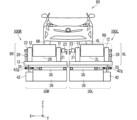
- Fig. 8 is a front view showing a schematic structure of a roller device 200 used in a conventional chassis dynamometer with a roller turning function as typified by Patent Document 2.
- Fig. 8 shows a front view seen from the front (+Y direction).
- Fig. 8 shows an XYZ orthogonal coordinate system.
- the roller device 200 shown in Fig. 8 is used as at least the two roller devices on the front wheel side.
- the roller device 200 has a roller device 200R for the right front tire 6R and a roller device 200L for the left front tire 6L.
- a roller device 200R for the right front tire 6R and a roller device 200L for the left front tire 6L.
- the roller device 200L as a representative of the roller devices 200R and 200L.
- the roller device 200L includes a roller turning mechanism 300L and a roller drive mechanism 80L as its main components.
- the roller swivel mechanism 300L includes as its main components a fixed base 36, a swivel motor 42, and a swivel bearing 38.
- the swivel bearing 38 is provided on the fixed base 36, and the swivel motor 42 is attached adjacent to the side of the fixed base 36.
- the swivel motor 42 is a geared motor whose speed can be controlled.
- a gear 42g is attached to the tip of the swivel motor 42, and the gear 42g meshes with a gear attached to the outer periphery of the swivel base 35. Therefore, the swivel base 35 can be rotated by the rotation of the swivel motor 42.
- the swivel bearing 38 rotatably supports the swivel base 35, and the swivel base 35 is rotated by the power of the swivel motor 42 around the center of the swivel bearing 38.
- the roller swivel mechanism 300L has a swivel base 35 that is rotated by the swivel motor 42.
- roller drive mechanism 80L above the roller turning mechanism 300L turns in conjunction with the turning of the turning base 35 in the roller turning mechanism 300L. Therefore, the roller turning mechanism 300L can perform a roller turning operation that turns the roller pair 20.
- roller drive mechanism 80L having the roller pair 20 is provided on the swivel base 35.
- the roller drive mechanism 80L for the twin roller configuration includes as its main components a roller drive motor 48, an encoder 49, a coupling 43, a reducer 5 consisting of a gear box, etc., a roller pair 20, and a rotating shaft 41.
- the rotating shaft 41 forms a pair of rotating shafts 41 corresponding to the roller pair 20.
- the roller drive motor 48 and the reducer 5 are fixed onto the swivel base 35, and the roller drive motor 48, which serves as the drive source, drives and rotates each of the pair of rotating shafts 41 via the coupling 43 and the reducer 5.
- the rotational motion transmission function is branched into two within the reducer 5, enabling the pair of rotating shafts 41 to be driven and rotated.
- the rotational speed of each of the roller pairs 20, which is based on the rotational speed of the roller drive motor 48 is measured by the encoder 49.
- the measurement result of the encoder 49 is also used as a feedback signal for controlling the roller drive motor 48.
- a pair of roller bearing pedestals are provided on the swivel base 35 so as to straddle the roller drive motor 48, and the pair of rotating shafts 41 support the roller pair 20 rotatably between the reducer 5 and the pair of roller bearing pedestals.
- a pair of rotating shafts 41 are attached so as to pass through the center of each roller pair 20, allowing the roller pair 20 to perform a rotational motion in conjunction with the rotation of the pair of rotating shafts 41.
- the roller drive mechanism 80L can perform a roller drive operation that rotates the front roller 20F, which is the first roller, and a roller drive operation that rotates the rear roller 20B, which is the second roller.
- a twin roller configuration can be achieved by providing two roller drive mechanisms 80L compatible with a single roller configuration on the swivel base 35.
- the roller device 200R is mounted on the swivel base 35, similar to the roller device 200L, and includes a roller turning mechanism 300R and a roller drive mechanism 80R as its main components.
- the configuration and operation of each part of the roller turning mechanism 300R are the same as those of the roller turning mechanism 300L, and the configuration and operation of each part of the roller drive mechanism 80R are the same as those of the roller drive mechanism 80L.
- roller device 200L and roller device 200R are collectively referred to, they may simply be referred to as “roller device 200", and when roller pair 20L and roller pair 20R are collectively referred to, they may simply be referred to as “roller pair 20".
- roller drive mechanism 80L and roller drive mechanism 80R may be simply referred to as “roller drive mechanism 80", and when referring to roller turning mechanism 300L and roller turning mechanism 300R collectively, they may be simply referred to as “roller turning mechanism 300".
- Figures 9 and 10 are explanatory diagrams each showing a schematic diagram of the torque measurement mechanism in the roller drive mechanism 80R. Each of Figures 9 and 10 shows an XYZ Cartesian coordinate system.
- a roller drive motor 48 is supported on the swivel base 35 via a rocking bearing 47 and an oil film 46. As shown in Figure 9, two combinations of rocking bearings 47 and oil films 46 are provided for the roller drive motor 48.
- the roller drive motor 48 is supported in a floating state above the swivel base 35 via the oil film 46, which has the advantage that loss in the rotational direction of the roller drive motor 48 is small.
- a load cell 45 is attached to the side of the roller drive motor 48 via a torque arm 44.
- the reaction force of the roller drive motor 48 can be measured by the load cell 45 because the roller drive motor 48 is supported in a free state in the rotation direction.
- roller drive mechanism 80L also has a torque measurement mechanism similar to that of roller drive mechanism 80R.
- the roller device 200 in the conventional chassis dynamometer shown in Figures 8 to 10 required a roller drive mechanism 80 to rotate the roller pair 20.
- the roller drive mechanism 80 requires relatively large components such as a roller drive motor 48 and a reducer 5.
- the roller device 200 is usually installed in an area called an underground pit below the floor surface on which the vehicle 60 is placed, but because the size of the roller device 200 is large, it was necessary to take measures such as creating a deep underground pit and securing a relatively large installation space for the roller device 200.
- the purpose of this disclosure is to provide a chassis dynamometer structure that solves the above problems and reduces the installation space required.
- the chassis dynamometer disclosed herein is a chassis dynamometer equipped with a roller device, the roller device including a roller on which a vehicle tire is placed and a cooler provided outside the roller, the roller including a roller outer frame body and a motor provided within the roller outer frame body, the motor including a motor rotor, a stator structure arranged to surround the motor rotor, a rotating shaft connected to the motor rotor, and an oscillating shaft connected to the stator structure, the rotating shaft and the oscillating shaft being oriented relative to the roller.
- the roller device further includes a rotating bearing stand that rotatably supports the rotating shaft and a swinging bearing stand that swingably supports the swinging shaft, the rotating shaft rotates in conjunction with the rotational movement of the motor rotor, the swinging shaft does not rotate in conjunction with the rotational movement of the motor rotor, the rotating shaft is rotatably attached to the roller outer frame, the roller outer frame has a roller opening, and the cooler supplies cooling air to the motor through the roller opening of the roller outer frame.
- rollers of the roller device in the chassis dynamometer disclosed herein have a motor inside the roller outer frame, so the roller outer frame can be directly rotated by the motor's rotating shaft.
- the chassis dynamometer disclosed herein can reduce the size of the device by eliminating the need to provide an external motor for driving the rotation of the roller and a power transmission mechanism to the roller.
- the roller device in the chassis dynamometer disclosed herein is equipped with a cooler provided outside the roller, the motor inside the roller outer frame can be effectively cooled by supplying cooling air to the motor through a roller opening provided in the roller outer frame.
- FIG. 1 is an explanatory diagram showing a schematic structure of a roller device used in a chassis dynamometer according to an embodiment of the present invention
- 2 is an explanatory diagram of the roller drive mechanism shown in FIG. 1 as viewed from the side
- FIG. FIG. 4 is an explanatory diagram showing details of a roller driving mechanism.
- FIG. 4 is an explanatory diagram showing the principle of torque measurement in a roller drive mechanism.
- 4 is an explanatory diagram showing details of the internal structure of rollers and the like in a roller drive mechanism.
- FIG. FIG. 6 is an explanatory diagram showing a schematic cross-sectional structure taken along line AA in FIG. 5. 6 is an explanatory diagram illustrating a schematic planar structure of the blocking plate illustrated in FIG. 5 .
- FIG. 1 is a front view showing the structure of a roller device used in a conventional chassis dynamometer.
- FIG. 9 is a first explanatory diagram illustrating a torque measuring mechanism in the roller drive mechanism illustrated in FIG. 8 .
- FIG. 2 is a second explanatory diagram illustrating a torque measuring mechanism in a roller drive mechanism.
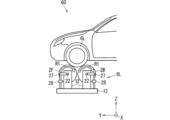
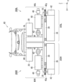
- Fig. 1 is an explanatory diagram showing a schematic structure of a roller device 100 used in a chassis dynamometer of this embodiment.
- Fig. 1 shows a front view seen from the front (+Y direction).
- An XYZ orthogonal coordinate system is depicted in Fig. 1.
- the roller devices 100 shown in Fig. 1 are used as at least the two roller devices on the front wheel side.
- the roller device 100 has a roller device 100R for the right front tire 6R and a roller device 100L for the left front tire 6L.
- the roller device 100R includes a roller drive mechanism 8R and a roller turning mechanism 30R as main components
- the roller device 100L includes a roller drive mechanism 8L and a roller turning mechanism 30L as main components.
- the roller devices 100R and 100L each further include a cooling fan 50, which is a cooler not shown in FIG. 1.
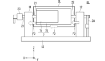
- FIG. 2 is an explanatory diagram of roller drive mechanism 8L as viewed from the side (-X direction).
- FIG. 3 is an explanatory diagram showing the details of roller drive mechanism 8L.
- An XYZ orthogonal coordinate system is depicted in each of FIG. 2 and FIG. 3.
- roller device 100L will be described as a representative of roller device 100R and roller device 100L with reference to these figures.
- the roller device 100L includes a roller turning mechanism 30L and a roller drive mechanism 8L as its main components.
- the roller turning mechanism 30L includes as its main components a fixed base 36, a turning motor 42, and a turning bearing 38.
- the turning bearing 38 is provided on the fixed base 36, and the turning motor 42 is attached adjacent to the side of the fixed base 36.
- the swivel motor 42 is a geared motor whose speed can be controlled.
- a gear 42g is attached to the tip of the swivel motor 42, and the gear 42g meshes with a gear attached to the outer periphery of the swivel base 35. Therefore, the swivel base 35 can be rotated by the rotation of the swivel motor 42.
- the swivel bearing 38 rotatably supports the swivel base 35, and the swivel base 35 is rotated by the power of the swivel motor 42 around the center of the swivel bearing 38.
- the roller swivel mechanism 30L has a swivel base 35 that is rotated by the swivel motor 42.
- roller drive mechanism 8L above the roller turning mechanism 30L turns in conjunction with the turning of the turning base 35 in the roller turning mechanism 30L. Therefore, the roller turning mechanism 30L can perform a roller turning operation that turns the roller 2L.
- the roller turning mechanism 30L performs a roller turning operation with the roller drive mechanism 8L as the turning object.
- the roller drive mechanism 8L includes the roller 2, a cooling fan 50 (described later), a rotating bearing stand 11, and a swinging bearing stand 12 as its main components.
- roller drive mechanism 8L The roller drive mechanism 8L having the roller 2L is mounted on the swivel base 35.
- the roller drive mechanism 8L for the twin roller configuration includes as its main components a base 13, a roller 2L, a rotating bearing stand 11, a swinging bearing stand 12, a rotating shaft 21, a swinging shaft 22, a torque arm 27, and a load cell 28.
- the rotating shaft 21 becomes a pair of rotating shafts 21
- the swinging shaft 22 becomes a pair of swinging shafts 22.
- the base 13 is fixed onto the swivel base 35, and the rotating bearing stand 11 and the oscillating bearing stand 12 are erected on the base 13.
- the rotating bearing stand 11 rotatably supports the rotating shaft 21, and the oscillating bearing stand 12 oscillates and supports the oscillating shaft 22.
- a roller 2L is provided between the rotating bearing base 11 and the oscillating bearing base 12. As will be described in detail later, the roller 2L rotates with the rotation of the rotating shaft 21.
- the rotating shaft 21 is attached so as to pass through the center of the roller 2L, so that the roller 2L can rotate together with the rotation of the rotating shaft 21.
- An encoder 23 is attached to the rotating shaft 21, and the rotation speed of the roller 2 is directly measured by the encoder 23.
- the measurement result of the encoder 23 is also used as a feedback signal for controlling the motor 7.
- roller 2L shown in Figures 1 and 3 corresponds to either the front roller 2F or the rear roller 2B shown in Figure 2.
- the roller drive mechanism 8L executes a roller drive operation that rotates the roller 2L.
- the roller 2L corresponds to the front roller 2F, which is the first roller, the front roller 2F is rotated, and when the roller 2L corresponds to the rear roller 2B, which is the second roller, the rear roller 2B is rotated.
- stator structure 72 is provided independently of the motor rotor 71 in terms of rotational movement so that it is not linked to the rotational movement of the motor rotor 71.
- the oscillating shaft 22 is attached to the stator structure 72 that is not linked to the rotational movement of the motor rotor 71.
- a load cell 28 is attached to the end of the oscillating shaft 22 via a torque arm 27.
- Figure 4 is an explanatory diagram showing the torque measurement principle in the roller drive mechanism 8L.
- the figure shows an XYZ orthogonal coordinate system.
- a reaction force along the rotation direction of the motor 7 built into the roller 2 is transmitted to the oscillating shaft 22. Therefore, the reaction force of the motor 7 can be measured by the load cell 28.
- the reaction force of the motor 7 reflects the reaction force caused by the acceleration of the front roller 2F, the force applied by the tire 6L to the front roller 2F during a running test of the vehicle 60, etc. Specifically, when a force is applied from the tire 6 to the roller 2 during a running test of the vehicle 60, the reaction force of the motor 7 is transmitted as a swinging state of the swing shaft 22.
- reaction force of the motor 7 transmitted to the oscillating shaft 22 can be measured by the load cell 28 connected to the oscillating shaft 22 via the torque arm 27.
- the roller drive mechanism 8L has a torque measurement mechanism including a torque arm 27 and a load cell 28 corresponding to the oscillating shaft 22. As shown in FIG. 2, a torque measurement mechanism (torque arm 27 + load cell 28) is provided corresponding to the oscillating shaft 22 of each of the front roller 2F and the rear roller 2B.
- the roller 2L includes as its main components a roller outer frame 10 and a motor 7 provided within the roller outer frame.
- the motor 7 includes as its main components a motor rotor 71, a stator structure 72, and the aforementioned rotating shaft 21 and oscillating shaft 22.
- the stator structure 72 is disposed so as to surround the motor rotor 71, the rotating shaft 21 is connected to the motor rotor 71, and the oscillating shaft 22 is connected to the stator structure 72.
- the rotating shaft 21 and the oscillating shaft 22 are disposed opposite each other with respect to the roller 2L.
- the rotating shaft 21 rotates in conjunction with the rotational movement of the motor rotor 71.
- the stator structure 72 is not linked to the rotational movement of the motor rotor 71, and is provided independently of the motor rotor 71 in terms of rotational movement.
- the roller device 100R is mounted on a swivel base 35, similar to the roller device 100L, and includes a roller turning mechanism 30R and a roller drive mechanism 8R as its main components.
- the configuration and operation of each part of the roller turning mechanism 30R are the same as those of the roller turning mechanism 30L, and the configuration and operation of each part of the roller drive mechanism 8R are the same as those of the roller drive mechanism 8L.
- roller device 100L and roller device 100R when referring to roller device 100L and roller device 100R collectively, they may be referred to simply as “roller device 100”, when referring to roller pair 20L and roller pair 20R collectively, they may be referred to simply as “roller pair 20”, and when referring to roller 2L and roller 2R collectively, they may be referred to simply as “roller 2”.
- roller drive mechanism 8L and the roller drive mechanism 8R may be referred to simply as the “roller drive mechanism 8"
- roller turning mechanism 30L and the roller turning mechanism 30R when referring to the roller drive mechanism 8L and the roller drive mechanism 8R collectively, they may be referred to simply as the “roller turning mechanism 30".
- the chassis dynamometer of this embodiment has a vehicle fixing mechanism that fixes the vehicle 60 placed on the roller device 100 when conducting a running test.
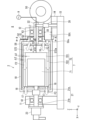
- FIG. 5 is an explanatory diagram showing the details of the internal structure of the roller 2, the rotary bearing pedestal 11, and the oscillating bearing pedestal 12 in the roller drive mechanism 8.
- FIG. 6 is an explanatory diagram showing a schematic view of the A-A cross-sectional structure in FIG. 5.
- the rotating bearing stand 11 has a bearing 61 inside, and the rotating shaft 21 is inserted into the raceway (inner ring) of this bearing 61, so that the rotating bearing stand 11 rotatably supports the rotating shaft 21.
- the rotating shaft 21 includes a rotor direct-connected shaft 21a inside the roller 2 and a bearing stand holding shaft 21b outside the roller 2.
- the rotor direct-connected shaft 21a and the bearing stand holding shaft 21b are connected by drilling a hole in the axial direction of the bearing stand holding shaft 21b and inserting the rotor direct-connected shaft 21a into this hole.
- the vertically long rectangular area shown in Figure 5 is also included in the bearing stand holding shaft 21b.
- the roller outer frame 10 has a cylindrical structure with a circular roller bottom surface, which includes a first roller bottom surface on the oscillating shaft 22 side and a second roller bottom surface on the rotating shaft 21 side.
- a bearing 62 is provided in the central region of the bottom surface of the first roller of the roller outer frame 10.
- the bottom surface of the first roller protrudes partially toward the oscillating bearing stand 12 in order to accommodate the bearing 62.
- the rotating shaft 21 is fixed to the center of the bottom surface of the second roller of the roller outer frame body 10. In this way, the rotating shaft 21, which can rotate in conjunction with the rotational movement of the motor rotor 71, is attached to the roller outer frame body 10. In other words, the rotating shaft 21 is attached to the roller outer frame body 10 so as to be able to rotate the roller outer frame body 10.
- the oscillating bearing stand 12 has a bearing 63 inside, and the roller outer frame 10 has a bearing 62 in the central region of the bottom surface of the first roller.
- the oscillating shaft 22 is supported by the roller outer frame 10 and the oscillating bearing stand 12 in a manner that allows the oscillating shaft 22 to oscillate by inserting the oscillating shaft 22 into the raceways (inner rings) of the bearings 62 and 63.
- the stator structure 72 includes a motor stator 721 and a motor case 722 as its main components.
- the motor stator 721 is disposed so as to surround the motor rotor 71, and the motor case 722 houses the motor stator 721 with an internal case space S72 secured between the motor stator 721 and the motor case 722.
- the motor stator 721 is not linked to the rotational movement of the motor rotor 71, and is provided independently of the motor rotor 71 in terms of rotational movement.
- the motor case 722 is also provided independently of the motor rotor 71 in terms of rotational movement.
- the motor stator 721 and motor case 722 sway due to the reaction force of the motor 7 being applied to them.
- the motor case 722 has a cylindrical structure with a circular case bottom, and the case bottom includes a first case bottom on the oscillating shaft 22 side and a second case bottom on the rotating shaft 21 side.
- the end of the oscillating shaft 22 is connected to the center of the first case bottom surface of the motor case 722. In this way, the oscillating shaft 22, which is not linked to the rotational movement of the motor rotor 71, is attached to the motor case 722.
- an outer case space S8 is provided between the first roller bottom surface of the roller outer frame body 10 and the first case bottom surface of the motor case 722.
- the power source for driving the motor 7 is supplied to the motor 7 inside the roller outer frame 10 from the AC power source 9, which is an external alternating current power source, via the motor wiring L7. That is, the AC power source 9 and the motor 7 are electrically connected by the motor wiring L7. A part of the motor wiring L7 is provided inside the oscillating shaft 22. That is, the motor 7 is an AC motor.
- the circular roller outer frame body bottom surface 10S of the roller outer frame body 10 on the oscillating bearing base 12 side shown in FIG. 6 becomes the first roller bottom surface.
- a plurality of roller openings 15 are provided discretely around the oscillating shaft 22 and the bearing 62 along a circumferential region C10 centered on the oscillating shaft 22.
- Each of the plurality of roller openings 15 is provided penetrating the roller outer frame body bottom surface 10S. In this way, the plurality of roller openings 15 are provided along a circumferential region C10 centered on the oscillating shaft 22.
- a plurality of case openings 16 are provided through the first case bottom surface of the motor case 722, each of which communicates with the case internal space S72.
- the cooling fan 50 which is a cooler provided outside the roller 2, has a cooling air outlet body 50t that blows out cooling air F2, and is positioned so that the cooling air outlet 50o of the cooling air outlet body 50t faces a part of the circumferential area C10 of the bottom surface 10S of the roller outer frame body.
- a duct space S5 is provided through the oscillating bearing base 12, and the cooling fan 50 is arranged in such a manner that the cooling air blowing body 50t is inserted into the duct space S5.
- a part of the cooling fan 50 is fixed onto a fan mounting base 14 provided on the base 13.
- the cooling fan 50 which is a cooler, can supply cooling air F2 from one of the multiple roller openings 15 in the bottom surface 10S of the roller outer frame body into the case outer space S8 by blowing out cooling air F2 from the cooling air outlet 50o of the cooling air outlet body 50t. Then, the cooling air F2 can be supplied from the case outer space S8 to the case inner space S72 in the roller outer frame body 10 via the multiple case openings 16.
- the cooling air F2 blown out from the cooling air outlet 50o of the cooling air outlet body 50t is supplied through one of the multiple roller openings 15 along the axial direction (X direction) of the oscillating shaft 22.
- the axial distance d8 which is the spacing in the Y direction in the case outer space S8, is set to be narrower than the axial distance d72, which is the spacing in the X direction in the bottom-to-bottom space S72a included in the case inner space S72.
- the bottom-to-bottom space S72a is the space in the case inner space S72 between the first roller bottom surface of the roller outer frame body 10 and the first case bottom surface of the motor case 722.
- a shield plate 52 is provided to cover the outer area of the circumferential region C10 on the bottom surface 10S of the roller outer frame body, other than the area facing the cooling air outlet 50o of the cooling air outlet main body 50t.
- FIG. 7 is an explanatory diagram showing a schematic planar structure of the blocking plate 52.
- the XYZ Cartesian coordinate system is shown in the figure.
- a circumferential region C10 is provided on the bottom surface 10S of the roller outer frame, centered on the oscillating shaft 22, outside the bearing 62 when viewed in a planar view in the YZ plane.
- the blocking plate 52 is provided to cover most of the circumferential region C10.
- the only circumferential region C10 that is not covered by the blocking plate 52 is the duct space S5 and its surroundings.
- the cooling air outlet 50o is present within the duct space S5. Therefore, the blocking plate 52 is provided to cover the area outside the outlet, other than the area facing the cooling air outlet 50o, of the circumferential region C10 on the bottom surface 10S of the roller outer frame.
- the roller outer frame 10 has a plurality of roller openings 17 (second roller openings) that penetrate the second roller bottom surface. Therefore, the roller openings that penetrate the two bottom surfaces of the roller outer frame 10 include a plurality of roller openings 15 (first roller openings) that penetrate the first roller bottom surface, and a plurality of roller openings 17 (second roller openings) that penetrate the second roller bottom surface.
- the motor case 722 has a plurality of case openings 18 (second case openings) that penetrate the second case bottom surface and communicate with the case internal space S72. Therefore, the case openings that penetrate the two bottom surfaces of the motor case 722 include a plurality of case openings 16 (first case openings) that penetrate the first case bottom surface, and a plurality of case openings 18 (second case openings) that penetrate the second case bottom surface.
- the roller outer frame 10 In the chassis dynamometer of this embodiment, the roller outer frame 10, the motor stator 721, and the motor case 722 have dimensional characteristics that satisfy the following inequality (1).
- ID2-ED1 indicates the inner diameter of the motor case 722
- ED1 indicates the outer diameter of the motor stator 721
- ID0 indicates the inner diameter of the roller outer frame 10
- ED2 indicates the outer diameter of the motor case 722.
- the roller 2 of the roller device 100 in the chassis dynamometer of this embodiment has a motor 7 within the roller outer frame body 10, so that the roller outer frame body 10 can be directly rotated by the rotating shaft 21 connected to the motor rotor 71 of the motor 7.
- the chassis dynamometer of this embodiment can reduce the size of the device by eliminating the need to provide an external motor and a power transmission mechanism to the roller outside the roller.
- roller drive motor 48 corresponds to the external motor
- reducer 5 for the roller pair 20 corresponds to the power transmission mechanism to the rollers.
- the motor 7 is built into the roller outer frame 10 of the roller 2, eliminating the need for a power transmission mechanism such as a speed reducer 5. This allows the size of the roller drive mechanism 8 in the height direction (Z direction) to be significantly reduced, and the installation space and cost of the roller device 100 can be reduced even when the roller turning mechanism 30 is included.
- the roller drive mechanism 8 which is a main component of the roller device 100 in the chassis dynamometer of this embodiment, is equipped with a cooling fan 50, which is a cooler provided outside the roller 2. Therefore, by supplying cooling air F2 from the cooling fan 50 into the roller outer frame 10 through one of the multiple roller openings 15 in the roller outer frame 10, the motor 7 present inside the roller outer frame 10 can be effectively cooled.
- the cooling fan 50 in the chassis dynamometer of this embodiment can supply cooling air F2 to the case interior space S72 via multiple roller openings 15 provided on the first roller bottom surface of the roller outer frame body 10 and multiple case openings 16 provided on the first case bottom surface of the motor case 722.
- the chassis dynamometer of this embodiment can effectively cool the motor 7 and the roller outer frame 10 by applying the cooling air F2 directly to the surface of the motor stator 721 and the inner surface of the roller outer frame 10.
- the cooling effect can be enhanced by making the surface of the motor stator 721 have a fin structure.
- the chassis dynamometer of this embodiment which has a motor 7 built into the roller 2, can perform running tests on the vehicle 60 without any problems.
- roller outer frame 10 In the roller 2 of the chassis dynamometer of this embodiment, the roller outer frame 10, motor stator 721, and motor case 722 have dimensional characteristics that satisfy the above-mentioned inequality (1).
- This dimensional characteristic is a characteristic that sets the spatial volume that requires cooling in relation to the passage of the cooling air F2 to be larger than the spatial volume that does not require cooling.
- the chassis dynamometer of this embodiment has the dimensional characteristics described above, and is therefore able to effectively cool the motor rotor 71 and motor stator 721, which are the main parts of the motor 7 that require cooling.
- the multiple roller openings 15 that become the first roller openings are provided along a circumferential region C10 centered on the oscillating shaft 22. Therefore, even when the roller outer frame body 10 is rotating, the cooling air F2 can be blown out from the cooling air outlet 50o of the cooling air blowing body 50t of the cooling fan 50, so that the cooling air F2 can be reliably supplied to the case outer space S8 through one of the multiple roller openings 15.
- the roller drive mechanism 8 in the chassis dynamometer of this embodiment is equipped with a shield plate 52 that covers the outer area of the circumferential region C10 other than the area facing the cooling air outlet 50o, so that the cooling air F2 supplied to the case outer space S8 does not leak out of the roller outer frame body 10 from any of the multiple roller openings 15.
- the cooling air F2 blown out from the cooling air outlet 50o accumulates in the case external space S8.
- the area outside the outlet which is the majority of the circumferential area C10, is blocked by the blocking plate 52, so the cooling air F2 that accumulates in the case external space S8 does not leak to the outside, but is accurately guided to the case internal space S72 via the multiple case openings 16.
- the chassis dynamometer of this embodiment can improve the cooling effect of the motor 7 by increasing the efficiency of supplying cooling air F2 from the case exterior space S8 to the case interior space S72.
- the chassis dynamometer of this embodiment has multiple roller openings 17 (second roller openings) on the second roller bottom surface of the roller outer frame 10, and multiple case openings 18 (second case openings) on the second case bottom surface of the motor case 722. Therefore, the multiple roller openings 15 (first roller openings) can be used as supply ports for cooling air, and the multiple roller openings 17 can be used as exhaust ports for cooling air F2.
- a cooling air passage is secured by the multiple roller openings 15, the outer case space S8, the multiple case openings 16 (first case openings), the inner case space S72, the multiple case openings 18, and the multiple roller openings 17.
- a space corresponding to the case outer space S8 exists between the second roller bottom surface of the roller outer frame body 10 and the second roller bottom surface of the motor case 722.
- the multiple roller openings 17 and the multiple case openings 18 are located opposite each other in the YZ plane.
- the chassis dynamometer of this embodiment can more effectively cool the motor 7 disposed within the roller outer frame 10 of the roller 2 by flowing the cooling air F2 through the cooling air passage using the cooling fan 50, which serves as a cooler.
- the chassis dynamometer of this embodiment can test a variety of vehicles 60, including roller turning motion, by rotating the roller drive mechanism 8 as a turning object using the roller turning mechanism 30.
- the roller drive mechanism 8 includes the roller 2, the cooling fan 50, the rotating bearing stand 11, and the oscillating bearing stand 12 as its main components.
- the chassis dynamometer of this embodiment uses a load cell 28 connected to the oscillating shaft 22 via a torque arm 27 to measure the reaction force of the motor 7 transmitted to the oscillating shaft 22.
- the reaction force of the motor 7 during a running test of the vehicle 60 is accurately reflected in the oscillating state of the oscillating shaft 22.
- the chassis dynamometer of this embodiment can use the load cell 28 to accurately measure the reaction force of the motor 7 during a running test of the vehicle 60.
- the roller device 100 in the chassis dynamometer of this embodiment further includes an encoder 23 attached to the rotating shaft 21.
- the encoder 23 directly measures the rotational speed of the roller 2.
- the roller device 100 rotates the roller outer frame 10 directly using the rotating shaft 21, so the encoder 23 can accurately measure the rotational speed of the rotating shaft 21 as the rotational speed of the roller 2.
- the roller drive mechanism 8 included in the roller device 100 in the chassis dynamometer of this embodiment has an AC power source 9 for the motor 7, which is an AC motor, and motor wiring L7.
- the chassis dynamometer of this embodiment can smoothly supply AC power from the AC power source 9 provided outside the roller 2 to the motor 7 provided inside the roller 2 via the motor wiring L7, part of which is provided inside the oscillating shaft 22.
- the roller device 100 shown in this embodiment is shown as a device for placing the tire 6 on the front wheel side of the vehicle 60, but the roller device 100 may also be used as a device for placing the tire 6 on the rear wheel side of the vehicle 60. Also, if the roller for placing the tire 6 on one of the tires 6 on the front wheel side and the rear wheel side of the vehicle 60 is a free roller, there is no need to provide a roller device 100 on the free roller side.
- the roller turning mechanism 30 is typically provided on the roller device 100 on which the front tire 6 is placed between the front and rear tires 6.
Landscapes
- Physics & Mathematics (AREA)
- General Physics & Mathematics (AREA)
- Chemical & Material Sciences (AREA)
- Engineering & Computer Science (AREA)
- Combustion & Propulsion (AREA)
- Rollers For Roller Conveyors For Transfer (AREA)
- Connection Of Motors, Electrical Generators, Mechanical Devices, And The Like (AREA)
- Motor Or Generator Frames (AREA)
Priority Applications (5)
| Application Number | Priority Date | Filing Date | Title |
|---|---|---|---|
| CN202380077909.4A CN120202398A (zh) | 2023-10-23 | 2023-10-23 | 底盘测功机 |
| JP2024527842A JP7680178B1 (ja) | 2023-10-23 | 2023-10-23 | シャーシダイナモメータ |
| KR1020257015830A KR20250086767A (ko) | 2023-10-23 | 2023-10-23 | 차대 동력계 |
| PCT/JP2023/038191 WO2025088674A1 (ja) | 2023-10-23 | 2023-10-23 | シャーシダイナモメータ |
| MX2025005872A MX2025005872A (es) | 2023-10-23 | 2025-05-20 | Dinamometro de chasis |
Applications Claiming Priority (1)
| Application Number | Priority Date | Filing Date | Title |
|---|---|---|---|
| PCT/JP2023/038191 WO2025088674A1 (ja) | 2023-10-23 | 2023-10-23 | シャーシダイナモメータ |
Publications (1)
| Publication Number | Publication Date |
|---|---|
| WO2025088674A1 true WO2025088674A1 (ja) | 2025-05-01 |
Family
ID=95515366
Family Applications (1)
| Application Number | Title | Priority Date | Filing Date |
|---|---|---|---|
| PCT/JP2023/038191 Pending WO2025088674A1 (ja) | 2023-10-23 | 2023-10-23 | シャーシダイナモメータ |
Country Status (5)
| Country | Link |
|---|---|
| JP (1) | JP7680178B1 (https=) |
| KR (1) | KR20250086767A (https=) |
| CN (1) | CN120202398A (https=) |
| MX (1) | MX2025005872A (https=) |
| WO (1) | WO2025088674A1 (https=) |
Citations (7)
| Publication number | Priority date | Publication date | Assignee | Title |
|---|---|---|---|---|
| JPS531579A (en) | 1976-06-28 | 1978-01-09 | Hitachi Ltd | Chassis cynamometer of roller type |
| JPH0616004B2 (ja) * | 1989-07-11 | 1994-03-02 | 本田技研工業株式会社 | 駆動輪スリップ制御装置の機能検査方法 |
| JP2001519905A (ja) * | 1997-04-02 | 2001-10-23 | ルーランド エレクトリック カンパニー | 内蔵式の液体冷却部および潤滑部を有する電気的回転機械 |
| US20020043102A1 (en) * | 2000-10-13 | 2002-04-18 | Renk Aktiengesellschaft | Roller type test stand for testing motor vehicles and/or tires |
| JP3163882U (ja) * | 2010-08-25 | 2010-11-04 | 新明工業株式会社 | アライメントテスタ |
| CN113188817A (zh) * | 2021-04-25 | 2021-07-30 | 中车永济电机有限公司 | 一种超导电动悬浮推进系统控制开发辅助平台 |
| JP2023089808A (ja) | 2021-12-16 | 2023-06-28 | 東芝三菱電機産業システム株式会社 | 車両試験装置 |
-
2023
- 2023-10-23 JP JP2024527842A patent/JP7680178B1/ja active Active
- 2023-10-23 WO PCT/JP2023/038191 patent/WO2025088674A1/ja active Pending
- 2023-10-23 KR KR1020257015830A patent/KR20250086767A/ko active Pending
- 2023-10-23 CN CN202380077909.4A patent/CN120202398A/zh active Pending
-
2025
- 2025-05-20 MX MX2025005872A patent/MX2025005872A/es unknown
Patent Citations (7)
| Publication number | Priority date | Publication date | Assignee | Title |
|---|---|---|---|---|
| JPS531579A (en) | 1976-06-28 | 1978-01-09 | Hitachi Ltd | Chassis cynamometer of roller type |
| JPH0616004B2 (ja) * | 1989-07-11 | 1994-03-02 | 本田技研工業株式会社 | 駆動輪スリップ制御装置の機能検査方法 |
| JP2001519905A (ja) * | 1997-04-02 | 2001-10-23 | ルーランド エレクトリック カンパニー | 内蔵式の液体冷却部および潤滑部を有する電気的回転機械 |
| US20020043102A1 (en) * | 2000-10-13 | 2002-04-18 | Renk Aktiengesellschaft | Roller type test stand for testing motor vehicles and/or tires |
| JP3163882U (ja) * | 2010-08-25 | 2010-11-04 | 新明工業株式会社 | アライメントテスタ |
| CN113188817A (zh) * | 2021-04-25 | 2021-07-30 | 中车永济电机有限公司 | 一种超导电动悬浮推进系统控制开发辅助平台 |
| JP2023089808A (ja) | 2021-12-16 | 2023-06-28 | 東芝三菱電機産業システム株式会社 | 車両試験装置 |
Also Published As
| Publication number | Publication date |
|---|---|
| JP7680178B1 (ja) | 2025-05-20 |
| JPWO2025088674A1 (https=) | 2025-05-01 |
| MX2025005872A (es) | 2025-06-02 |
| KR20250086767A (ko) | 2025-06-13 |
| CN120202398A (zh) | 2025-06-24 |
Similar Documents
| Publication | Publication Date | Title |
|---|---|---|
| CN211178991U (zh) | 一种车辆测功机系统 | |
| JP2016004047A (ja) | 二重目的動力計 | |
| CN106945748B (zh) | 底盘总成及具有其的机器人和探测车辆 | |
| JP2013104554A (ja) | 車両用ボールタイプ等速ジョイント | |
| JP7680178B1 (ja) | シャーシダイナモメータ | |
| JP2024057101A (ja) | 変換テーブル作成方法 | |
| EP1347557A2 (en) | Integral axle generator assembly | |
| US8899296B2 (en) | Apparatus for servicing vehicle wheels | |
| CN106989760B (zh) | 旋转高低温试验箱 | |
| CN222291820U (zh) | 一种运输车的驱动模块及运输车 | |
| TWI908062B (zh) | 測試單元 | |
| CN206691249U (zh) | 底盘总成及具有其的机器人和探测车辆 | |
| JP5173445B2 (ja) | シャシーダイナモメータ | |
| TWM656943U (zh) | 一體式多層無遮蔽雲台裝置 | |
| JPH01172027A (ja) | ホイールドライブ装置 | |
| WO2021213066A1 (zh) | 驱动装置及具有其的agv | |
| JP3141570U (ja) | 二輪車駆動用ベルトの耐久試験機 | |
| JPWO2025088674A5 (https=) | ||
| WO2017026216A1 (ja) | 車両用モータ駆動装置 | |
| CN224103859U (zh) | 一种运输车的驱动模块及运输车 | |
| JP2512470Y2 (ja) | 渦電流式動力計 | |
| JPH0443801Y2 (https=) | ||
| CN110802612B (zh) | 圆柱坐标打磨机器人 | |
| CN113984667B (zh) | 工业内窥镜自动检测机构 | |
| JPH0192086A (ja) | ロボットの関節部 |
Legal Events
| Date | Code | Title | Description |
|---|---|---|---|
| ENP | Entry into the national phase |
Ref document number: 2024527842 Country of ref document: JP Kind code of ref document: A |
|
| WWE | Wipo information: entry into national phase |
Ref document number: 2024527842 Country of ref document: JP |
|
| WWE | Wipo information: entry into national phase |
Ref document number: CN2023800779094 Country of ref document: CN Ref document number: 202380077909.4 Country of ref document: CN |
|
| WWE | Wipo information: entry into national phase |
Ref document number: 202517045653 Country of ref document: IN |
|
| ENP | Entry into the national phase |
Ref document number: 20257015830 Country of ref document: KR Kind code of ref document: A |
|
| WWE | Wipo information: entry into national phase |
Ref document number: 2501003176 Country of ref document: TH |
|
| WWE | Wipo information: entry into national phase |
Ref document number: MX/A/2025/005872 Country of ref document: MX |
|
| WWP | Wipo information: published in national office |
Ref document number: 202517045653 Country of ref document: IN |
|
| WWP | Wipo information: published in national office |
Ref document number: MX/A/2025/005872 Country of ref document: MX |
|
| WWP | Wipo information: published in national office |
Ref document number: 1020257015830 Country of ref document: KR |
|
| 121 | Ep: the epo has been informed by wipo that ep was designated in this application |
Ref document number: 23956732 Country of ref document: EP Kind code of ref document: A1 |
|
| WWP | Wipo information: published in national office |
Ref document number: 202380077909.4 Country of ref document: CN |