WO2025083811A1 - 配管接続構造 - Google Patents
配管接続構造 Download PDFInfo
- Publication number
- WO2025083811A1 WO2025083811A1 PCT/JP2023/037703 JP2023037703W WO2025083811A1 WO 2025083811 A1 WO2025083811 A1 WO 2025083811A1 JP 2023037703 W JP2023037703 W JP 2023037703W WO 2025083811 A1 WO2025083811 A1 WO 2025083811A1
- Authority
- WO
- WIPO (PCT)
- Prior art keywords
- pipe
- radial direction
- connection structure
- inclined end
- end surface
- Prior art date
- Legal status (The legal status is an assumption and is not a legal conclusion. Google has not performed a legal analysis and makes no representation as to the accuracy of the status listed.)
- Pending
Links
Images






Classifications
-
- F—MECHANICAL ENGINEERING; LIGHTING; HEATING; WEAPONS; BLASTING
- F16—ENGINEERING ELEMENTS AND UNITS; GENERAL MEASURES FOR PRODUCING AND MAINTAINING EFFECTIVE FUNCTIONING OF MACHINES OR INSTALLATIONS; THERMAL INSULATION IN GENERAL
- F16L—PIPES; JOINTS OR FITTINGS FOR PIPES; SUPPORTS FOR PIPES, CABLES OR PROTECTIVE TUBING; MEANS FOR THERMAL INSULATION IN GENERAL
- F16L23/00—Flanged joints
- F16L23/12—Flanged joints specially adapted for particular pipes
-
- F—MECHANICAL ENGINEERING; LIGHTING; HEATING; WEAPONS; BLASTING
- F16—ENGINEERING ELEMENTS AND UNITS; GENERAL MEASURES FOR PRODUCING AND MAINTAINING EFFECTIVE FUNCTIONING OF MACHINES OR INSTALLATIONS; THERMAL INSULATION IN GENERAL
- F16L—PIPES; JOINTS OR FITTINGS FOR PIPES; SUPPORTS FOR PIPES, CABLES OR PROTECTIVE TUBING; MEANS FOR THERMAL INSULATION IN GENERAL
- F16L25/00—Construction or details of pipe joints not provided for in, or of interest apart from, groups F16L13/00 - F16L23/00
Definitions
- An embodiment of the present invention relates to a piping connection structure.
- flanges provided at the ends of the pipes are butted together and fastened together with multiple bolts.
- the end of one pipe may be inserted into the end of the other pipe, and the two pipes may be joined by welding, brazing, etc.
- the problem that this invention aims to solve is to provide a pipe connection structure that can easily connect pipes to each other while reducing the space required for connecting the pipes.
- the pipe connection structure of the embodiment connects the ends of a first pipe and a second pipe in the extension direction.
- Each of the first pipe and the second pipe includes a pipe body and a pair of connecting members.
- the pipe body has an end formed with an inclined end face that is inclined with respect to a plane perpendicular to the extension direction when viewed from the first radial direction of each pipe.
- the pair of connecting members are arranged on both sides in the first radial direction at the end of each pipe in the extension direction, and each protrudes outward in the first radial direction from the outer circumferential surface of the pipe body.
- FIG. 1 is an explanatory diagram showing a schematic configuration of a power conversion device including piping to which a piping connection structure according to an embodiment is applied;
- FIG. 1 is a perspective view showing a pipe connection structure according to an embodiment.
- FIG. 2 is an exploded perspective view of the pipe connection structure according to the embodiment.
- FIG. 2 is a side view showing the pipe connection structure according to the embodiment.
- 5 is an explanatory diagram showing an inclined end surface formed on an end of a split pipe in the pipe connection structure according to the embodiment, viewed from a normal direction.
- FIG. FIG. 2 is a side view showing the pipe connection structure according to the embodiment.
- FIG. 4 is an explanatory diagram showing a state in the middle of connecting split pipes to each other in the pipe connection structure of the embodiment.
- FIG. 5 is an explanatory diagram showing a force acting on a connection portion between split pipes in the pipe connection structure of the embodiment.
- FIG. FIG. 2 is an explanatory diagram illustrating a case where pipes to which the pipe connection structure of the embodiment is applied are arranged in parallel.
- FIG. 4 is an explanatory diagram showing a piping configuration in which split pipes are connected to each other by flanges, for comparison with the piping connection structure of the embodiment.
- FIG. 11 is an explanatory diagram of a case where split pipes connected to each other by flanges are arranged in parallel for comparison with the pipe connection structure of the embodiment.
- FIG. 1 is an explanatory diagram showing a schematic configuration of a power converter including piping to which a piping connection structure according to an embodiment of the present invention is applied.
- the power conversion device 1 according to the embodiment is provided in, for example, electrical equipment, etc.
- the power conversion device 1 is a switchboard, a distribution board, a control board, etc. constituting a power supply device, a motor drive device, etc.
- the power conversion device 1 includes a housing 3 and a plurality of devices 2 housed within the housing 3.
- the housing 3 is formed, for example, in the shape of a hollow rectangular box.
- the housing 3 has an openable door (not shown) on one side.
- Each of the multiple devices 2 includes various circuit components, such as semiconductor elements, conductors, fuses, capacitors, transformers, switches, circuit breakers, and measuring instruments. Each of the multiple devices 2 is fixed to the housing 3.
- the multiple devices 2 are connected to a water supply pipe 5 and a drain pipe 6.
- the water supply pipe 5 allows cooling water to be supplied to the devices 2 from outside the housing 3.
- Each of the multiple devices 2 is cooled by the cooling water supplied from the water supply pipe 5.
- the drain pipe 6 allows cooling water to be discharged from the devices 2 to outside the housing 3.
- the water supply pipe 5 includes, for example, a first water supply pipe 51, a second water supply pipe 52, and an external water supply pipe 53.
- the first water supply pipe 51 extends in the direction in which the multiple devices 2 are lined up.
- the first water supply pipe 51 is connected to each of the multiple devices 2 via a connection pipe 54.
- One end of the second water supply pipe 52 is connected to an end of the first water supply pipe 51 at a connection part J11.
- the second water supply pipe 52 is bent, for example, in an L-shape.
- the other end of the second water supply pipe 52 is connected to one end of the external water supply pipe 53 at a connection part J12.
- the external water supply pipe 53 is introduced into the housing 3 from outside the housing 3 through an opening 3h formed in the housing 3.
- the drainage piping 6 includes, for example, a first drainage pipe 61, a second drainage pipe 62, and an external drainage pipe 63.
- the first drainage pipe 61 extends in the direction in which the multiple devices 2 are lined up.
- the first drainage pipe 61 is connected to each of the multiple devices 2 via a connection pipe 64.
- One end of the second drainage pipe 62 is connected to the end of the first drainage pipe 61 at the connection part J21.
- the second drainage pipe 62 is bent, for example, in an L-shape.
- the other end of the second drainage pipe 62 is connected to one end of the external drainage pipe 63 at the connection part J22.
- the external drainage pipe 63 is introduced into the housing 3 from outside the housing 3 through an opening 3h formed in the housing 3.
- connection J11 between the first water supply pipe 51 and the second water supply pipe 52, the connection J12 between the second water supply pipe 52 and the external water supply pipe 53, the connection J21 between the first drainage pipe 61 and the second drainage pipe 62, and the connection J22 between the second drainage pipe 62 and the external drainage pipe 63 are arranged inside the housing 3.
- the connection J12 between the second water supply pipe 52 and the external water supply pipe 53 and the connection J22 between the second drainage pipe 62 and the external drainage pipe 63 are arranged in parallel to each other inside the housing 3.
- connection structure at each of the connection parts J11, J12, J21, and J22 will be described.
- the piping connection structure between the first water supply pipe 51 and the second water supply pipe 52 at connection part J11, the piping connection structure between the second water supply pipe 52 and the external water supply pipe 53 at connection part J12, the piping connection structure between the first drainage pipe 61 and the second drainage pipe 62 at connection part J21, and the piping connection structure between the second drainage pipe 62 and the external drainage pipe 63 at connection part J22 are similar to each other.
- Each pair of pipes connected by each piping connection structure is sometimes referred to as a "split pipe.”
- one split pipe is referred to as the first pipe 100A
- the other split pipe is referred to as the second pipe 100B
- the first water supply pipe 51 is referred to as the first pipe 100A
- the second water supply pipe 52 is referred to as the second pipe 100B
- the second water supply pipe 52 is referred to as the first pipe 100A
- the external water supply pipe 53 is referred to as the second pipe 100B
- the first drainage pipe 61 is referred to as the first pipe 100A
- the second drainage pipe 62 is referred to as the second pipe 100B
- the second drainage pipe 62 is referred to as the first pipe 100A
- the external drainage pipe 63 is referred to as the second pipe 100B.
- Fig. 2 is a perspective view showing the pipe connection structure of the embodiment
- Fig. 3 is an exploded perspective view showing the pipe connection structure of the embodiment
- Fig. 4 is a side view showing the pipe connection structure of the embodiment. 2 to 4
- the pipe connection structure Z of the embodiment includes a first pipe 100A, a second pipe 100B, and a fastening member 103 (see FIG. 2).
- the pipe connection structure Z of the embodiment is applied to a so-called straight pipe portion in which the first pipe 100A and the second pipe 100B extend in the same straight line in the extension direction (axial direction) Da.
- Each of the first pipe 100A and the second pipe 100B includes a pipe body 101 and a pair of plates (connecting members) 102.
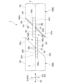
- FIG. 5 is an explanatory diagram of an inclined end surface formed on an end of a split pipe in a pipe connection structure according to an embodiment, viewed from a direction intersecting the inclined end surface (for example, a normal direction to the inclined end surface).
- Each of the pipe bodies 101 of the first pipe 100A and the second pipe 100B extends in the extension direction Da of the first pipe 100A and the second pipe 100B.
- An inclined end surface 104 is formed at the end 101a of each pipe body 101. As shown in FIG. 4, the inclined end surface 104 is formed along a plane inclined at a predetermined angle ⁇ with respect to a plane perpendicular to the extension direction Da.
- the inclined end surface 104 is inclined so as to rotate around a diameter D1 along a first radial direction Dr1 described later.
- a seal groove 104m that accommodates a seal ring 110 described later is formed around the entire circumference of the inclined end surface 104 of at least one of the pipe bodies 101 of the first pipe 100A and the second pipe 100B (only one in the embodiment).
- the pair of plates 102 are arranged at the end 101a of the piping body 101 on both sides of the piping body 101 in the radial direction Dr.
- the pair of plates 102 are arranged on both sides of the piping body 101 in a first radial direction Dr1, which is one direction of the radial direction Dr of the piping body 101.
- the inclined end surface 104 of the piping body 101 is inclined from one side of the extension direction Da to the other side with respect to a second radial direction Dr2 that is perpendicular to the first radial direction Dr1 in the radial direction Dr.
- Each plate 102 protrudes from the outer peripheral surface 101f of the piping body 101 outward in the radial direction Dr of the piping body 101.
- Each plate 102 is flat and parallel to the first radial direction Dr1 and the extension direction Da (flat and perpendicular to the second radial direction Dr2).
- the plates 102 of each divided pipe are arranged to face each other across the central axis C of the piping body 101 in the second radial direction Dr2 when viewed from the first radial direction Dr1.
- each plate 102 on one side in the extension direction Da is joined (e.g., welded) to the outer peripheral surface 101f of the pipe body 101.
- the tip 102b of each plate 102 on the other side in the extension direction Da protrudes from the inclined end surface 104 to one side in the extension direction Da.
- the position of the plate 102 of the first pipe 100A relative to the inclined end surface 104 (the amount of protrusion from the inclined end surface 104)
- the position of the plate 102 of the second pipe 100B relative to the inclined end surface 104 (the amount of protrusion from the inclined end surface 104) are the same. All of the plates 102 in the embodiment have the same configuration. Therefore, when welding the plates 102 to the ends of the pipes 100A and 100B, it is possible to perform welding using a common jig or other equipment.
- each divided pipe has opposing surfaces 102f that face each other in the second radial direction Dr2.
- Each opposing surface 102f is formed flat overall so as to be along a plane perpendicular to the second radial direction Dr2.
- Each opposing surface 102f is not limited to a flat surface, but has a fine uneven shape including a locking claw 105 described later.
- Each opposing surface 20f is formed so as to be along the central axis C of the pipe main body 101 when viewed from the first radial direction Dr1.
- Each opposing surface 102f is arranged so as to form an acute angle with the inclined end surface 104 of the pipe main body 101 when viewed from the first radial direction Dr1. That is, in each plate 102, the opposing surface 102f is formed on the side that forms an acute angle with the inclined end surface 104 of the pipe main body 101 when viewed from the first radial direction Dr1.
- a locking claw (convex portion) 105 is formed on each opposing surface 102f.
- the locking claw 105 extends, for example, along the first radial direction Dr1 (along a direction perpendicular to the extension direction Da).
- a plurality of locking claws 105 are formed on the opposing surface 102f at equal intervals in the extension direction Da.
- Each locking claw 105 has a locking surface 105f.
- the locking surface 105f is formed, for example, facing one side of the extension direction Da (base portion 102a).
- the locking surface 105f is a surface that intersects with the extension direction Da, and is, for example, a flat surface inclined with respect to a plane perpendicular to the extension direction Da.
- a recess is formed to align (fit) the locking claws 105 of the opposing surface 102f of the other plate 102 that faces in the second radial direction Dr2.
- the pair of opposing opposing surfaces 102f are formed with uneven shapes that can fit into each other.
- each plate 102 has an insertion hole (through hole) 107 through which a bolt 103a of a fastening member 103 described later is inserted.
- the insertion holes 107 are formed in each plate 102, for example, at two locations spaced apart in the extension direction Da. Each insertion hole 107 penetrates each plate 102 in the second radial direction Dr2.
- the first pipe 100A and the second pipe 100B are connected with the inclined end face 104 of the first pipe 100A and the inclined end face 104 of the second pipe 100B butting against each other.
- An annular seal ring 110 (see FIG. 3) is sandwiched between the inclined end face 104 of the first pipe 100A and the inclined end face 104 of the second pipe 100B.
- the seal ring 110 is positioned relative to the inclined end face 104 by being accommodated in a seal groove 104m formed in one of the inclined end faces 104.
- FIG. 6 is a side view showing the pipe connection structure of the embodiment.
- the first pipe 100A and the second pipe 100B are connected in a state in which the opposing surfaces 102f of the pair of plates 102 of the first pipe 100A and the opposing surfaces 102f of the pair of plates 102 of the second pipe 100B abut against each other in the second radial direction Dr2.
- the opposing surfaces 102f of the plates 102 of the first pipe 100A and the opposing surfaces 102f of the plates 102 of the second pipe 100B abut against each other in the extension direction Da at the locking surfaces 105f of the locking claws 105. This restricts the relative movement of the first pipe 100A and the second pipe 100B in the direction away from each other in the extension direction Da.
- FIG. 7 is an explanatory diagram showing a state in the middle of connecting the split pipes to each other in the pipe connection structure of the embodiment.
- the seal ring 110 is crushed between the inclined end surface 104 of the first pipe 100A and the inclined end surface 104 of the second pipe 100B, while the inclined end surfaces 104 are brought closer together in the extension direction Da.
- the elastic force of the seal ring 110 acts to separate the inclined end surfaces 104 in the normal direction. This elastic force acts in a direction that presses the opposing surfaces 102f of the pair of opposing plates 102 together.
- the inclined end surface 104 of the first pipe 100A and the inclined end surface 104 of the second pipe 100B come into contact with each other.
- the opposing surface 102f of the plate 102 of the first pipe 100A and the opposing surface 102f of the plate 102 of the second pipe 100B come into contact with each other in the second radial direction Dr2.
- the plate 102 of the first pipe 100A and the plate 102 of the second pipe 100B are aligned with each other in the extension direction Da.
- the through hole 107 of the plate 102 of the first pipe 100A and the through hole 107 of the plate 102 of the second pipe 100B are coaxially overlapped with each other. In this state, each plate 102 of the first pipe 100A and the corresponding plate 102 of the second pipe 100B can be fastened with the fastening member 103.
- a gap may be formed between the inclined end surface 104 of the first pipe 100A and the inclined end surface 104 of the second pipe 100B. This gap is set to a range that ensures sealing by the seal ring 110.
- the locking claws 105 on the opposing surface 102f of the plate 102 of the first pipe 100A and the locking claws 105 on the opposing surface 102f of the plate 102 of the second pipe 100B engage with each other.
- the relative movement of the first pipe 100A and the second pipe 100B in the direction away from each other in the extension direction Da is firmly restrained by the recessed and protruding engagement of the opposing surfaces 102f.
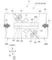
- FIG. 8 is an explanatory diagram showing forces acting on a connection portion between split pipes in the pipe connection structure of the embodiment.
- the first pipe 100A and the second pipe 100B are connected to each other in a state in which the opposing surfaces 102f of the plates 102 of the first pipe 100A and the opposing surfaces 102f of the corresponding plates 102 in the second pipe 100B are abutted against each other by the fastening member 103.
- a fastening force F1 by the fastening member 103 acts in the second radial direction Dr2 between the opposing surfaces 102f of the plates 102 of the first pipe 100A and the opposing surfaces 102f of the corresponding plates 102 in the second pipe 100B.
- Fig. 10 is an explanatory diagram showing a configuration of a pipe in which split pipes are flange-connected to each other for comparison with the pipe connection structure of the embodiment.
- Fig. 11 is an explanatory diagram showing a case in which split pipes in which split pipes are flange-connected to each other are arranged in parallel for comparison with the pipe connection structure of the embodiment.
- the plate 102 of the first pipe 100A and the plate 102 of the second pipe 100B have opposing surfaces 102f that face each other in the second radial direction Dr2.
- the opposing surfaces 102f of the plate 102 of the first pipe 100A and the opposing surfaces 102f of the plate 102 of the second pipe 100B have uneven shapes that fit into each other. This restricts the first pipe 100A and the second pipe 100B from moving relative to each other in the extension direction Da in a direction away from each other, thereby increasing the connection strength of the pipes 100A and 100B.
- each plate 102 may be formed on a side that forms an obtuse angle with the inclined end surface 104 when viewed from the first radial direction Dr1.
- part of the fastening force fastening the plates 102 together is added to the force that brings the inclined end surfaces 104 closer to each other, thereby increasing the surface pressure between the inclined end surfaces 104 and ensuring the sealing performance of the seal ring 110.
- the connecting member connecting the pipes 100A and 100B is not limited to the plate 102 fastened in the second radial direction Dr2, and may be a member fastened in a direction intersecting the second radial direction Dr2.
- Only one connecting member in the first radial direction Dr1 may be directly fastened by a fastening member, and the other connecting member may be configured by a hook, a hinge, or the like and fastened passively.
- the uneven shape of the opposing surface 102f of each plate 102 may have a curved shape such as a wave shape, instead of the multiple locking claws 105 and the recesses between the adjacent claws.
- the uneven shape of the opposing surface 102f of each plate 102 may be any shape that restricts the relative axial movement of the split pipes by fitting together.
Landscapes
- Engineering & Computer Science (AREA)
- General Engineering & Computer Science (AREA)
- Mechanical Engineering (AREA)
- Flanged Joints, Insulating Joints, And Other Joints (AREA)
- Joints With Sleeves (AREA)
Priority Applications (3)
| Application Number | Priority Date | Filing Date | Title |
|---|---|---|---|
| JP2024543842A JP7728469B1 (ja) | 2023-10-18 | 2023-10-18 | 配管接続構造 |
| PCT/JP2023/037703 WO2025083811A1 (ja) | 2023-10-18 | 2023-10-18 | 配管接続構造 |
| CN202380079006.XA CN120187975A (zh) | 2023-10-18 | 2023-10-18 | 配管连接构造 |
Applications Claiming Priority (1)
| Application Number | Priority Date | Filing Date | Title |
|---|---|---|---|
| PCT/JP2023/037703 WO2025083811A1 (ja) | 2023-10-18 | 2023-10-18 | 配管接続構造 |
Publications (1)
| Publication Number | Publication Date |
|---|---|
| WO2025083811A1 true WO2025083811A1 (ja) | 2025-04-24 |
Family
ID=95448006
Family Applications (1)
| Application Number | Title | Priority Date | Filing Date |
|---|---|---|---|
| PCT/JP2023/037703 Pending WO2025083811A1 (ja) | 2023-10-18 | 2023-10-18 | 配管接続構造 |
Country Status (3)
| Country | Link |
|---|---|
| JP (1) | JP7728469B1 (https=) |
| CN (1) | CN120187975A (https=) |
| WO (1) | WO2025083811A1 (https=) |
Citations (6)
| Publication number | Priority date | Publication date | Assignee | Title |
|---|---|---|---|---|
| JPS51124215U (https=) * | 1975-04-03 | 1976-10-07 | ||
| JPS5230722B2 (https=) * | 1972-04-25 | 1977-08-10 | ||
| JPS5951286U (ja) * | 1982-09-29 | 1984-04-04 | 笹山 守 | 管継手 |
| CN202274228U (zh) * | 2011-09-29 | 2012-06-13 | 庄天文 | 快速拆装轴流泵出水管道 |
| JP2015098988A (ja) * | 2013-11-20 | 2015-05-28 | アイシン精機株式会社 | 配管接続方法及び配管接続継手 |
| CN213685696U (zh) * | 2020-11-07 | 2021-07-13 | 金螳螂精装科技(苏州)有限公司 | 一种室内装修用组件式管道 |
-
2023
- 2023-10-18 CN CN202380079006.XA patent/CN120187975A/zh active Pending
- 2023-10-18 JP JP2024543842A patent/JP7728469B1/ja active Active
- 2023-10-18 WO PCT/JP2023/037703 patent/WO2025083811A1/ja active Pending
Patent Citations (6)
| Publication number | Priority date | Publication date | Assignee | Title |
|---|---|---|---|---|
| JPS5230722B2 (https=) * | 1972-04-25 | 1977-08-10 | ||
| JPS51124215U (https=) * | 1975-04-03 | 1976-10-07 | ||
| JPS5951286U (ja) * | 1982-09-29 | 1984-04-04 | 笹山 守 | 管継手 |
| CN202274228U (zh) * | 2011-09-29 | 2012-06-13 | 庄天文 | 快速拆装轴流泵出水管道 |
| JP2015098988A (ja) * | 2013-11-20 | 2015-05-28 | アイシン精機株式会社 | 配管接続方法及び配管接続継手 |
| CN213685696U (zh) * | 2020-11-07 | 2021-07-13 | 金螳螂精装科技(苏州)有限公司 | 一种室内装修用组件式管道 |
Also Published As
| Publication number | Publication date |
|---|---|
| JPWO2025083811A1 (https=) | 2025-04-24 |
| JP7728469B1 (ja) | 2025-08-22 |
| CN120187975A (zh) | 2025-06-20 |
Similar Documents
| Publication | Publication Date | Title |
|---|---|---|
| JP2538261Y2 (ja) | ハウジング形管継手 | |
| EP1767842B1 (en) | Housing type joint | |
| JP7728469B1 (ja) | 配管接続構造 | |
| JP2024061833A (ja) | 樹脂管の接続装置 | |
| US4541817A (en) | Drive shaft assembly | |
| JP2015137683A (ja) | フランジ接合部補強構造及びそれに用いられる環状保護部材 | |
| JP2015034605A (ja) | 管継手 | |
| JPH09163562A (ja) | 水冷母線の接続部 | |
| JP7528330B2 (ja) | 接合部補強構造 | |
| US11309771B2 (en) | Cooling jacket and cooling unit | |
| JPH04351309A (ja) | 鋼構造物のボルト接合構造 | |
| JP7444700B2 (ja) | 樹脂管の接続装置 | |
| JP2012013151A (ja) | 管継手 | |
| JP2024126586A (ja) | 締結部材用の取付部材 | |
| JP2970565B2 (ja) | 導波管接続フランジ | |
| JPH0729354Y2 (ja) | 管継手 | |
| JP7414322B1 (ja) | フランジ付流体管の接合構造 | |
| JPH0755426Y2 (ja) | 管継手 | |
| JP5315187B2 (ja) | ハウジング形管継手 | |
| JPH0729355Y2 (ja) | 管継手 | |
| JP4149036B2 (ja) | 管体フランジ部漏洩補修機構 | |
| JP2002327881A (ja) | 流体配管用継手 | |
| US20250154988A1 (en) | Industrial machine | |
| JP2025027677A (ja) | フランジ補強装置 | |
| US20250214228A1 (en) | Coupling structure and parallel link robot |
Legal Events
| Date | Code | Title | Description |
|---|---|---|---|
| ENP | Entry into the national phase |
Ref document number: 2024543842 Country of ref document: JP Kind code of ref document: A |
|
| WWE | Wipo information: entry into national phase |
Ref document number: 2024543842 Country of ref document: JP |
|
| WWE | Wipo information: entry into national phase |
Ref document number: 202517044416 Country of ref document: IN |
|
| WWE | Wipo information: entry into national phase |
Ref document number: 202380079006.X Country of ref document: CN |
|
| WWP | Wipo information: published in national office |
Ref document number: 202517044416 Country of ref document: IN |
|
| 121 | Ep: the epo has been informed by wipo that ep was designated in this application |
Ref document number: 23954975 Country of ref document: EP Kind code of ref document: A1 |
|
| WWP | Wipo information: published in national office |
Ref document number: 202380079006.X Country of ref document: CN |