WO2025074870A1 - 磁気ギアード回転電機 - Google Patents
磁気ギアード回転電機 Download PDFInfo
- Publication number
- WO2025074870A1 WO2025074870A1 PCT/JP2024/033414 JP2024033414W WO2025074870A1 WO 2025074870 A1 WO2025074870 A1 WO 2025074870A1 JP 2024033414 W JP2024033414 W JP 2024033414W WO 2025074870 A1 WO2025074870 A1 WO 2025074870A1
- Authority
- WO
- WIPO (PCT)
- Prior art keywords
- magnetic
- stator
- electric machine
- rotating electric
- rotor
- Prior art date
- Legal status (The legal status is an assumption and is not a legal conclusion. Google has not performed a legal analysis and makes no representation as to the accuracy of the status listed.)
- Pending
Links
Images









Classifications
-
- H—ELECTRICITY
- H02—GENERATION; CONVERSION OR DISTRIBUTION OF ELECTRIC POWER
- H02K—DYNAMO-ELECTRIC MACHINES
- H02K16/00—Machines with more than one rotor or stator
- H02K16/02—Machines with one stator and two or more rotors
-
- H—ELECTRICITY
- H02—GENERATION; CONVERSION OR DISTRIBUTION OF ELECTRIC POWER
- H02K—DYNAMO-ELECTRIC MACHINES
- H02K7/00—Arrangements for handling mechanical energy structurally associated with dynamo-electric machines, e.g. structural association with mechanical driving motors or auxiliary dynamo-electric machines
- H02K7/10—Structural association with clutches, brakes, gears, pulleys or mechanical starters
Definitions
- This disclosure relates to a magnetically geared rotating electric machine.
- magnetic-geared rotating electric machines of the magnetic flux modulation type have been researched and developed to achieve high torque density.
- a magnetic-geared rotating electric machine a high-speed rotor on the inner diameter side is rotated by three-phase AC current applied to the stator coil, and a low-speed rotor equivalent to the output shaft is rotated using the principle of magnetic gears.
- a magnetic-geared rotating electric machine has two rotors and operates the two rotors using modulated wave magnetic flux, so various magnetic fluxes generate torque ripple. As a result, the torque ripple is larger than that of conventional rotating electric machines.
- This disclosure has been made to solve the above-mentioned problems, and aims to provide a magnetic-geared rotating electric machine that can reduce torque ripple caused by the secondary component of the induced voltage.
- the magnetic-geared rotating electric machine disclosed herein comprises a stator having a stator core with multiple teeth, a coil wound around the stator core, and stator magnets mounted on the teeth; a first rotor having multiple pole pieces arranged circumferentially and mounted across a gap from the stator; and a second rotor having multiple rotor magnets arranged circumferentially and mounted across a gap from the first rotor.
- the pole pieces of the first rotor are configured with a circumferential skew structure, and the stator magnet of the stator has multiple magnetic poles divided along the axial direction by a number of divisions corresponding to the skew structure, and the polarity of adjacent magnetic poles in the axial direction is reversed.
- the magnetic-geared rotating electric machine disclosed herein has a first rotor with pole pieces configured with a circumferential skew structure, a stator magnet of a stator with multiple magnetic poles divided along the axial direction by a number of divisions corresponding to the skew structure, and the polarity of adjacent magnetic poles in the axial direction is reversed, thereby reducing torque ripple caused by the secondary component of the induced voltage.
- FIG. 2 is a perspective view of a magnetic-geared rotating electric machine of a first comparative example according to the first embodiment
- FIG. 4 is a cross-sectional view of a magnetic-geared rotating electric machine of a first comparative example according to the first embodiment
- FIG. 13 is a diagram showing an induced voltage waveform in a magnetic-geared rotating electric machine of Comparative Example 1 according to the first embodiment.
- FIG. 11 is a characteristic diagram of a magnetic-geared rotating electric machine of Comparative Example 1 according to the first embodiment.
- FIG. 13 is a table showing winding coefficients of secondary components of induced voltages in magnetic-geared rotating electric machines according to comparative examples 1 to 4 relating to embodiment 1.
- FIG. 11 is a cross-sectional view of a magnetic-geared rotating electric machine of a second comparative example related to the first embodiment.
- FIG. 13 is a diagram showing an induced voltage waveform in a magnetic-geared rotating electric machine of Comparative Example 2 related to the first embodiment.
- FIG. 11 is a characteristic diagram of a magnetic-geared rotating electric machine of Comparative Example 2 related to the first embodiment.
- FIG. 11 is a cross-sectional view of a magnetic-geared rotating electric machine of a third comparative example related to the first embodiment.
- FIG. 13 is a diagram showing an induced voltage waveform in a magnetic-geared rotating electric machine of Comparative Example 3 related to Embodiment 1.
- FIG. 11 is a characteristic diagram of a magnetic-geared rotating electric machine of Comparative Example 3 related to the first embodiment.
- FIG. 11 is a cross-sectional view of a magnetic-geared rotating electric machine of Comparative Example 4 related to Embodiment 1.
- FIG. 13 is a diagram showing an induced voltage waveform in a magnetic-geared rotating electric machine of Comparative Example 4 related to the first embodiment.
- FIG. 13 is a characteristic diagram of a magnetic-geared rotating electric machine of Comparative Example 4 related to the first embodiment.
- 1 is a perspective view of a magnetic-geared rotating electric machine according to a first embodiment, with a stator removed; 1 is a cutaway perspective view of a stator of a magnetic-geared rotating electric machine according to a first embodiment; 4 is a diagram showing an induced voltage waveform in the magnetic-geared rotating electric machine according to the first embodiment;
- FIG. 13 is a diagram showing an induced voltage waveform in the magnetic-geared rotating electric machine according to the first embodiment.
- FIG. 4 is a characteristic diagram of the magnetic-geared rotating electric machine according to the first embodiment.
- FIG. 4 is a diagram showing an induced voltage waveform in the magnetic-geared rotating electric machine according to the first embodiment;
- FIG. 4 is a characteristic diagram of the magnetic-geared rotating electric machine according to the first embodiment.
- FIG. 13 is a diagram showing a cogging torque waveform in a magnetic-geared rotating electric machine of Comparative Example 5 according to the second embodiment.
- FIG. 13 is a characteristic diagram of a magnetic-geared rotating electric machine of Comparative Example 5 according to the second embodiment.
- 13 is a diagram showing a cogging torque waveform in a magnetic-geared rotating electric machine according to the second embodiment.
- FIG. FIG. 11 is a characteristic diagram of a magnetic-geared rotating electric machine according to the second embodiment.
- FIG. 13 is a diagram showing a transmission torque waveform in a magnetic-geared rotating electric machine of Comparative Example 6 related to Embodiment 3.
- 13 is a diagram showing a transmission torque waveform in a magnetic-geared rotating electric machine according to the third embodiment.
- FIG. FIG. 11 is a cutaway perspective view of a magnetic-geared rotating electric machine according to a fourth embodiment.
- FIG. 11 is a cutaway perspective view of a stator of a magnetic-geared rotating electric machine according to a fourth embodiment.
- 13 is a diagram for explaining the structure of a low-speed rotor of a magnetic-geared rotating electric machine according to embodiment 5.
- FIG. FIG. 13 is a cross-sectional view of a magnetic-geared rotating electric machine according to a sixth embodiment.
- FIG. 13 is a cutaway perspective view of a stator of a magnetic-geared rotating electric machine according to a sixth embodiment.
- the structure of the magnetic-geared rotating electric machine in this disclosure is described as the structure of a magnetic-geared motor or magnetic-geared generator in which a high-speed rotor, which is a second rotor, a low-speed rotor, which is a first rotor, and a stator are assembled in that order from the inner diameter side to the outer diameter side.
- a structure in which a stator, a low-speed rotor, and a high-speed rotor are assembled in that order from the inner diameter side to the outer diameter side may also be used.
- a magnetic-geared rotating electric machine according to a first embodiment for carrying out the present disclosure applies a stage skew to a low-speed rotor and divides a stator magnet of a stator in the axial direction in accordance with the stage skew of the low-speed rotor.
- a magnetic-geared rotating electric machine of a comparative example in which stage skew or the like is not applied to the low-speed rotor will be described.
- the magnetic-geared rotating electric machine for carrying out the present disclosure will be described as being driven by three-phase AC current.
- FIG. 1 is a perspective view of a magnetic-geared rotating electric machine of Comparative Example 1 in accordance with the present embodiment 1.
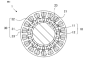
- FIG. 1 shows the appearance of the magnetic-geared rotating electric machine 1 of Comparative Example 1.
- This magnetic-geared rotating electric machine 1 is composed of, in order from the inner diameter side, a high-speed rotor 10 having a rotor magnet 12 on the surface of a cylindrical rotor core 11, a low-speed rotor 20 composed of a plurality of magnetic pole pieces 21, and a stator 30 in which a stator magnet 32 is incorporated into the teeth of a stator core 31 and a coil 33 is wound around it.
- the high-speed rotor 10, the low-speed rotor 20, and the stator 30 are each arranged coaxially with a gap therebetween.
- the direction parallel to the central axis of rotation of the high-speed rotor 10 and the low-speed rotor 20 is called the axial direction
- the direction perpendicular to the central axis of rotation is called the radial direction
- the direction rotating around the central axis of rotation is called the circumferential direction.
- the inner diameter side is the direction approaching the central axis of rotation in the radial direction
- the outer diameter side is the direction moving away from the central axis of rotation in the radial direction.
- Stator magnets 32 are incorporated into the tips of the teeth of the stator core 31, forming a consequent pole structure.
- a consequent pole structure is a structure in which the polarity of the stator magnets 32 is the same for all of the gaps, the magnetization direction is along the radial direction, and the teeth of the stator core 31 have the opposite polarity to the stator magnets 32.
- the magnetization direction of the stator magnets 32 is not limited to along the radial direction, and may be parallel oriented, polar anisotropic oriented, etc., as long as magnetic flux flows in and out of the surface of the stator magnet 32 facing the gap.
- Figure 2 is a cross-sectional view perpendicular to the axial direction of the magnetic-geared rotating electric machine of Comparative Example 1 shown in Figure 1.
- the number of pole pairs in the high-speed rotor 10 is 6, the number of pole pieces in the low-speed rotor 20 is 24, and the number of teeth in the stator 30 is 18. Therefore, the reduction ratio between the high-speed rotor 10 and the low-speed rotor 20 is 4, which is 24 divided by 6.
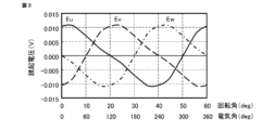
- Figure 3 is a diagram showing the induced voltage waveform in the magnetic-geared rotating electric machine of Comparative Example 1 shown in Figure 1.
- the horizontal axis is the rotation angle
- the vertical axis is the induced voltage. Note that the horizontal axis also shows the electrical angle.
- the solid line is the induced voltage of the U phase
- the dashed line is the induced voltage of the V phase
- the dashed-dotted line is the induced voltage of the W phase.
- the induced voltage waveform shown in Figure 3 is when the rotation speed of the high-speed rotor 10 is 60 rpm and the rotation speed of the low-speed rotor 20 is 15 rpm since the reduction ratio is 4.
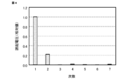
- Figure 4 is a characteristic diagram of the induced voltage waveform shown in Figure 3 when frequency analysis is performed.
- the horizontal axis is the order and the vertical axis is the induced voltage.
- the vertical axis shows the induced voltage normalized with the fundamental wave component set to 1. From Figure 4, it can be confirmed that in the magnetic-geared rotating electric machine of Comparative Example 1, a secondary component of the induced voltage is generated that is not generated in a rotating electric machine with a single rotor. This secondary component of the induced voltage is caused by a modulated wave magnetic flux generated by the magnetomotive force of the rotor magnet of the high-speed rotor and the magnetic flux modulation of the permeance of the low-speed rotor.
- the modulated wave magnetic flux of the 30 pole pairs interlinks with the coil at twice the frequency of the fundamental wave. Therefore, the modulated wave magnetic flux of the 30 pole pairs generates an induced voltage with twice the frequency of the fundamental wave, that is, a secondary induced voltage per one electrical angle cycle.
- the induced voltage of the fundamental wave occurs in the order of U phase, V phase, and W phase
- the secondary induced voltage occurs in the order of U phase, W phase, and V phase
- the torque ripple due to the secondary induced voltage occurs as a third-order component per one electrical angle cycle.
- Figure 5 is a table showing the winding coefficient of the secondary component of the induced voltage for combinations of the ratios of the number of pole pairs of the high-speed rotor, the number of pole pieces of the low-speed rotor, and the number of stator teeth in magnetic-geared rotating electric machines of Comparative Examples 1 to 4, including Comparative Examples 2 to 4 described below.
- Figure 5 shows four combinations of the ratios of the number of pole pairs of the high-speed rotor, the number of pole pieces of the low-speed rotor, and the number of stator teeth.
- the winding coefficient is given by the product of the short-pitch winding coefficient and the distributed winding coefficient.
- the short-pitch winding coefficient represents the rate of reduction in the induced voltage caused by the difference between the winding pitch and the pole pitch of the magnet
- the distributed winding coefficient represents the rate of reduction in the induced voltage caused by the phase difference of multiple windings connected in series within one phase.
- the secondary component of the induced voltage does not occur only when the coils of the same phase are connected in series.
- FIG 6 is a cross-sectional view of a magnetic-geared rotating electric machine of Comparative Example 2 relating to this embodiment.
- this magnetic-geared rotating electric machine 1 is a magnetic-geared rotating electric machine in which the high-speed rotor 10 has 8 pole pairs, the low-speed rotor 20 has 26 magnetic pole pieces, and the stator 30 has 18 teeth.
- the ratio of the number of pole pairs of the high-speed rotor: the number of magnetic pole pieces of the low-speed rotor: the number of teeth of the stator is 4:13:9.
- the reduction ratio is 3.25, which is 13 divided by 4.
- Figure 7 is a diagram showing the induced voltage waveform in the magnetic-geared rotating electric machine of Comparative Example 2 shown in Figure 6.
- the horizontal axis is the rotation angle
- the vertical axis is the induced voltage. Note that the horizontal axis also shows the electrical angle.
- the solid line is the induced voltage of the U phase
- the dashed line is the induced voltage of the V phase
- the dashed-dotted line is the induced voltage of the W phase.
- the induced voltage waveform shown in Figure 7 is when the rotation speed of the high-speed rotor 10 is 60 rpm and the reduction ratio is 3.25, so the rotation speed of the low-speed rotor 20 is 18.5 rpm.
- Figure 8 is a characteristic diagram when the induced voltage waveform shown in Figure 7 is subjected to frequency analysis.
- the horizontal axis is the order and the vertical axis is the induced voltage.
- the vertical axis shows the induced voltage normalized with the fundamental wave component set to 1. From Figure 8, it can be seen that in the magnetic-geared rotating electric machine of Comparative Example 2, the induced voltage contains a secondary component, but it is very small compared to the fundamental wave component. This is a reasonable result considering that in Figure 5, when the ratio of the number of pole pairs of the high-speed rotor: the number of pole pieces of the low-speed rotor: the number of teeth of the stator is 4:13:9, the winding coefficient of the secondary component of the induced voltage is 0.061.
- FIG 9 is a cross-sectional view of a magnetic-geared rotating electric machine of Comparative Example 3 relating to this embodiment.
- this magnetic-geared rotating electric machine 1 is a magnetic-geared rotating electric machine in which the high-speed rotor 10 has 5 pole pairs, the low-speed rotor 20 has 17 magnetic pole pieces, and the stator 30 has 12 teeth.
- the ratio of the number of pole pairs of the high-speed rotor: the number of magnetic pole pieces of the low-speed rotor: the number of teeth of the stator is 5:17:12.
- the reduction ratio is 3.4, which is 17 divided by 5.
- Figure 10 is a diagram showing the induced voltage waveform in the magnetic-geared rotating electric machine of Comparative Example 3 shown in Figure 9.
- the horizontal axis is the rotation angle
- the vertical axis is the induced voltage. Note that the horizontal axis also shows the electrical angle.
- the solid line is the induced voltage of the U phase
- the dashed line is the induced voltage of the V phase
- the dashed-dotted line is the induced voltage of the W phase.
- the induced voltage waveform shown in Figure 10 is when the rotation speed of the high-speed rotor 10 is 60 rpm and the reduction ratio is 3.4, so the rotation speed of the low-speed rotor 20 is 17.6 rpm.
- Figure 11 is a characteristic diagram when the induced voltage waveform shown in Figure 10 is subjected to frequency analysis.
- the horizontal axis is the order and the vertical axis is the induced voltage.
- the vertical axis shows the induced voltage normalized with the fundamental wave component induced voltage set to 1. From Figure 11, it can be seen that the induced voltage waveform in the magnetic-geared rotating electric machine of Comparative Example 3 does not contain a secondary component. This is a reasonable result considering that in Figure 5, when the ratio of the number of pole pairs of the high-speed rotor: the number of pole pieces of the low-speed rotor: the number of teeth of the stator is 5:17:12, the winding coefficient of the secondary component of the induced voltage is 0.
- Figure 12 is a cross-sectional view of a magnetic-geared rotating electric machine of Comparative Example 4 relating to this embodiment.
- this magnetic-geared rotating electric machine 1 is a magnetic-geared rotating electric machine in which the high-speed rotor 10 has 7 pole pairs, the low-speed rotor 20 has 25 magnetic pole pieces, and the stator 30 has 18 teeth.
- the ratio of the number of pole pairs of the high-speed rotor: the number of magnetic pole pieces of the low-speed rotor: the number of teeth of the stator is 7:25:18.
- the reduction ratio is 3.57, which is 25 divided by 7.
- Figure 13 is a diagram showing the induced voltage waveform in the magnetic-geared rotating electric machine of Comparative Example 4 shown in Figure 12.
- the horizontal axis is the rotation angle
- the vertical axis is the induced voltage. Note that the horizontal axis also shows the electrical angle.
- the solid line is the induced voltage of the U phase
- the dashed line is the induced voltage of the V phase
- the dashed-dotted line is the induced voltage of the W phase.
- the induced voltage waveform shown in Figure 13 is when the rotation speed of the high-speed rotor 10 is 60 rpm and the reduction ratio is 3.57, so the rotation speed of the low-speed rotor 20 is 16.8 rpm.
- Figure 14 is a characteristic diagram when the induced voltage waveform shown in Figure 13 is subjected to frequency analysis.
- the horizontal axis is the order and the vertical axis is the induced voltage.
- the vertical axis shows the induced voltage normalized with the fundamental wave component being 1. From Figure 14, it can be seen that the induced voltage waveform in the magnetic-geared rotating electric machine of Comparative Example 4 does not contain a secondary component. This is a reasonable result considering that in Figure 5, when the ratio of the number of pole pairs of the high-speed rotor: the number of pole pieces of the low-speed rotor: the number of teeth of the stator is 7:25:18, the winding coefficient of the secondary component of the induced voltage is 0.
- the ratio of the number of pole pairs of the high-speed rotor: the number of pole pieces of the low-speed rotor: the number of stator teeth is 7:22:15, and because the ratio of the number of teeth is odd, a secondary component of the induced voltage will be generated. Furthermore, even if the ratio of the number of stator teeth is an even number, for example, the ratio of the number of pole pairs of the high-speed rotor: the number of pole pieces of the low-speed rotor: the number of stator teeth shown in FIG.
- 5 is 5:17:12 and 7:25:18, if coils of the same phase are connected in parallel, a circulating current flows and a secondary component of the induced voltage is generated. If coils of the same phase are connected in series, no circulating current is generated and no secondary component of the induced voltage is generated.
- the magnetic-geared rotating electric machine of the present embodiment described below can be applied to magnetic-geared rotating electric machines that generate a secondary component of the induced voltage.
- skew refers to dividing the pole pieces or magnets or magnet magnetization into multiple stages in the axial direction and shifting each divided section in the circumferential direction.
- applying skew to the high-speed rotor is generally considered to prevent the generation of secondary components of induced voltage.
- the skew angle for reducing the secondary components of induced voltage is 360 degrees in electrical angle, calculated from the magnetic flux that generates the secondary components of induced voltage.
- stage skew is applied to the low-speed rotor.
- the fundamental wave magnetic flux of the induced voltage does not change whether or not the skew is applied to the low-speed rotor.
- the stator magnet and the modulated wave magnetic flux are no longer coupled, and even if the high-speed rotor rotates, the low-speed rotor does not rotate in synchronization with it.
- the stator magnet is divided in the axial direction corresponding to the stage skew of the low-speed rotor, and the polarity is reversed. It is also possible to reverse the magnetization direction of the stator magnet in the axial direction without dividing the stator magnet in the axial direction.
- FIG. 15 is a perspective view of the magnetic-geared rotating electric machine according to this embodiment, excluding the stator.
- FIG. 16 is a cutaway perspective view of the stator of the magnetic-geared rotating electric machine according to this embodiment.
- the number of pole pairs of the high-speed rotor is 6
- the number of pole pieces of the low-speed rotor is 24, and the number of teeth of the stator is 18.
- the magnetic-geared rotating electric machine according to this embodiment also has a stator core with a consequent pole structure, as in Comparative Examples 1 to 4. As shown in FIG.
- the fundamental wave magnetic flux generated by the magnetic flux modulation between the high-speed rotor and the low-speed rotor does not change, but the modulated wave magnetic flux that couples with the stator magnet is shifted by an electrical angle of 180 degrees up and down in the axial direction. Therefore, by shifting the phase of the magnetic flux of the stator magnet by 180 degrees up and down in the axial direction, it becomes possible to couple with the modulated wave magnetic flux. Shifting the phase of the magnetic flux by 180 degrees is equivalent to reversing the polarity.
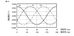
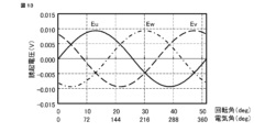
- FIG. 17 is a diagram showing the induced voltage waveform in the magnetic-geared rotating electric machine of the present embodiment shown in FIGS. 15 and 16.
- the horizontal axis is the rotation angle
- the vertical axis is the induced voltage. Note that the horizontal axis also shows the electrical angle.
- the solid line is the induced voltage of the U phase
- the dashed line is the induced voltage of the V phase
- the dashed-dotted line is the induced voltage of the W phase.
- the induced voltage waveform shown in FIG. 17 is when the rotation speed of the high-speed rotor 10 is 60 rpm and the reduction ratio is 4, so the rotation speed of the low-speed rotor 20 is 15 rpm.
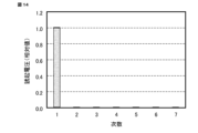
- Figure 18 is a characteristic diagram when the induced voltage waveform shown in Figure 17 is subjected to frequency analysis.
- the horizontal axis is the order and the vertical axis is the induced voltage.
- the vertical axis shows the induced voltage normalized with the fundamental wave component being 1.
- the high-speed rotor has 6 pole pairs
- the low-speed rotor has 24 pole pieces
- the stator has 18 teeth.
- the high-speed rotor has 8 pole pairs
- the low-speed rotor has 26 pole pieces
- the stator has 18 teeth.
- a two-stage skew as shown in FIG. 15 is applied to the low-speed rotor
- a split stator magnet with different polarities in the axial direction as shown in FIG. 16 is applied to the stator.
- the ratio of the number of pole pairs of the high-speed rotor: the number of pole pieces of the low-speed rotor: the number of stator teeth is 4:13:9.
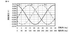
- FIG. 19 is a diagram showing the induced voltage waveform in another magnetic-geared rotating electric machine of this embodiment.
- the horizontal axis is the rotation angle
- the vertical axis is the induced voltage. Note that the horizontal axis also shows the electrical angle.
- the solid line is the induced voltage of the U phase
- the dashed line is the induced voltage of the V phase
- the dashed-dotted line is the induced voltage of the W phase.
- the induced voltage waveform shown in FIG. 19 is when the rotation speed of the high-speed rotor 10 is 60 rpm and the reduction ratio is 4, so the rotation speed of the low-speed rotor 20 is 15 rpm.
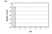
- Figure 20 is a characteristic diagram when the induced voltage waveform shown in Figure 19 is subjected to frequency analysis.
- the horizontal axis is the order and the vertical axis is the induced voltage.
- the vertical axis shows the induced voltage normalized with the fundamental wave component being 1.
- the number of pole pairs of the high-speed rotor is 8
- the magnetic pole pieces of the low-speed rotor are divided into multiple skewed stages offset by half a pitch in the circumferential direction, the stator magnet is divided in the axial direction by the same number of divisions as the skewed stages, and the polarity of adjacent divided stator magnets in the axial direction is reversed, thereby reducing the torque ripple caused by the secondary component of the induced voltage.
- magnetic-geared rotating electric machines with ratios of the number of pole pairs of the high-speed rotor, the number of magnetic pole pieces of the low-speed rotor, and the number of teeth of the stator of 1:4:3 and 4:13:9 have been mainly described.
- the reason for this is that the winding coefficient x reduction ratio, which is an index of torque density, is high.
- the winding coefficient x reduction ratio is high, the cogging torque and torque ripple are large, and the applications to which they can be applied are limited.
- the pole pieces of the low-speed rotor in the magnetic-geared rotating electric machine of this embodiment have a stepped skew structure
- the pole pieces may have a continuous skew structure. In the case of continuous skew, it is sufficient to apply a continuous skew of one pitch to the pole pieces.
- the stator the stator magnet may be divided in the axial direction by the number of divisions that can be divided, and the polarity of the divided stator magnets adjacent to each other in the axial direction may be reversed.
- the stator magnet may be a ring magnet with one pole pair of continuous skew magnetization, thereby reversing the polarity in the axial direction.
- continuous skew magnetization is a ring magnet in which the north and south poles are alternately magnetized in the circumferential direction, and the north and south poles are magnetized so that they are continuously inclined in the axial direction. Even if the pole pieces of the low-speed rotor have a continuously skewed structure, the secondary component of the induced voltage, which is the main cause of torque ripple, can be reduced to zero. In addition, by continuously skewing the pole pieces of the low-speed rotor, the cogging torque can be reduced more than with step-wise skew, expanding the range of applications in which magnetic-geared rotating electric machines can be used.
- the magnetic-geared rotating electric machine according to the second embodiment is a magnetic-geared rotating electric machine in which the high-speed rotor has 6 pole pairs, the low-speed rotor has 24 pole pieces, and the stator has 18 teeth.
- the ratio of the number of pole pairs of the high-speed rotor: the number of pole pieces of the low-speed rotor: the number of stator teeth is 1:4:3.
- the magnetic-geared rotating electric machine of this embodiment applies a two-stage skew as shown in FIG. 15 to the low-speed rotor, and applies a split stator magnet with different polarities in the axial direction as shown in FIG. 16 to the stator. In this embodiment, the effect of reducing cogging torque will be described.
- FIG. 21 is a diagram showing the cogging torque waveform in the magnetic-geared rotating electric machine of Comparative Example 5.
- the horizontal axis is the rotation angle
- the vertical axis is the cogging torque. Note that the horizontal axis also shows the electrical angle.
- the solid line represents the cogging torque of the high-speed rotor
- the dashed line represents the cogging torque of the low-speed rotor.
- Figure 22 is a characteristic diagram of the frequency analysis of the cogging torque waveform shown in Figure 21.
- the horizontal axis is the order and the vertical axis is the cogging torque.
- the cogging torque waveform in Figure 21 contains a third-order component and its double harmonic components per electrical angle cycle.
- the cogging torque of the high-speed rotor is the sum of the cogging torque between the high-speed rotor and the low-speed rotor and the cogging torque between the high-speed rotor and the stator.
- the cogging torque between the high-speed rotor and the low-speed rotor is composed of a third-order component and its double harmonic components.
- the cogging torque between the high-speed rotor and the stator is composed of a third-order component, which is the least common multiple of 1 and 3, and its multiple harmonic components.
- the cogging torque between the low-speed rotor and the stator is composed of a twelfth-order component, which is the least common multiple of the number of pole pieces of the low-speed rotor (4) and the number of poles of the stator magnet (6).
- Figure 23 shows the cogging torque waveform in the magnetic-geared rotating electric machine of this embodiment.
- the ratio of the number of pole pairs of the high-speed rotor: the number of magnetic pole pieces of the low-speed rotor: the number of teeth of the stator is 1:4:3, a two-stage skew as shown in Figure 15 is applied to the low-speed rotor, and a split stator magnet with different polarities in the axial direction as shown in Figure 16 is applied to the stator.
- the horizontal axis is the rotation angle
- the vertical axis is the cogging torque. Note that the horizontal axis also shows the electrical angle.
- the solid line indicates the cogging torque of the high-speed rotor
- the dashed line indicates the cogging torque of the low-speed rotor.
- FIG. 24 is a characteristic diagram obtained by frequency analysis of the cogging torque waveform shown in FIG. 23.
- the horizontal axis is the order
- the vertical axis is the cogging torque. Comparing FIG. 22 with FIG. 24, it can be seen that in the magnetic-geared rotating electric machine of this embodiment, the third-order component of the cogging torque can be reduced to almost zero. However, in the magnetic-geared rotating electric machine of this embodiment, because a two-stage skew is applied to the low-speed rotor, there is no reduction effect on the even-numbered multiples of the third-order component, and only the odd-numbered multiples of the third-order component (3rd, 9th, 15th, .... order components) can be reduced.
- two-stage skew reduces cogging torque is that magnetic flux with an opposite magnetic field direction is generated at each stage, canceling out the cogging torque.
- the phase difference at each stage is 180 degrees ( ⁇ ) electrical angle, and because the phase difference for even-numbered components is 2 ⁇ , the magnetic flux has the same magnetic field direction at each stage and is not cancelled out, whereas the phase difference for odd-numbered components is ⁇ , so the magnetic flux has the opposite magnetic field direction at each stage and is cancelled out.
- the magnetic-geared rotating electric machine of this embodiment can reduce the third-order components and their odd-multiple components in the cogging torque waveform, and is therefore effective in reducing cogging torque.
- the magnetic-geared rotating electric machine according to the third embodiment is a magnetic-geared rotating electric machine in which the high-speed rotor has 6 pole pairs, the low-speed rotor has 24 pole pieces, and the stator has 18 teeth.
- the ratio of the number of pole pairs of the high-speed rotor: the number of pole pieces of the low-speed rotor: the number of stator teeth is 1:4:3.
- the magnetic-geared rotating electric machine of this embodiment applies a two-stage skew as shown in FIG. 15 to the low-speed rotor, and applies a split stator magnet with different polarities in the axial direction as shown in FIG. 16 to the stator.
- the transmitted torque will be described.
- Figure 25 is a diagram showing the transmitted torque waveform in the magnetic-geared rotating electric machine of Comparative Example 6.
- the horizontal axis is the rotation angle
- the vertical axis is the transmitted torque. Note that the horizontal axis also shows the electrical angle.
- the solid line is the transmitted torque of the high-speed rotor
- the dashed line is the transmitted torque of the low-speed rotor. Note that the transmitted torque waveform shown in Figure 25 is the transmitted torque waveform obtained by rotating only the high-speed rotor with the low-speed rotor fixed.
- Figure 26 is a diagram showing the transmitted torque waveform in the magnetic-geared rotating electric machine of this embodiment.
- the ratio of the number of pole pairs of the high-speed rotor: the number of magnetic pole pieces of the low-speed rotor: the number of teeth of the stator is 1:4:3, a two-stage skew as shown in Figure 15 is applied to the low-speed rotor, and a split stator magnet with different polarities in the axial direction as shown in Figure 16 is applied to the stator.
- the horizontal axis is the rotation angle
- the vertical axis is the transmitted torque. Note that the horizontal axis also shows the electrical angle.
- the solid line indicates the transmitted torque of the high-speed rotor
- the dashed line indicates the transmitted torque of the low-speed rotor.
- FIG. 27 is a cutaway perspective view of a magnetic-geared rotating electric machine according to a fourth embodiment.
- the high-speed rotor is omitted.
- the pole piece 21 of the low-speed rotor 20 is divided into three in the axial direction.
- the pole piece 21 is composed of split pole pieces 21a and 21c located on the outer side in the axial direction and split pole piece 21b located in the center in the axial direction.
- the axial length of the split pole pieces 21a and 21c is half the axial length of the split pole piece 21b.
- the pole piece 21 is divided into three so as to be symmetrical with respect to the central plane in the axial direction, and the division ratio is 1:2:1.
- the split pole pieces 21a and 21b are provided with a half pitch offset in the circumferential direction
- the split pole pieces 21b and 21c are provided with a half pitch offset in the circumferential direction.
- FIG. 28 is a cutaway perspective view of the stator of the magnetic-geared rotating electric machine according to this embodiment.
- the stator magnet 32 of the stator 30 is divided into three in the axial direction.
- the stator magnet 32 is composed of split stator magnets 32a and 32c located on the outer side in the axial direction and split stator magnet 32b located in the center in the axial direction.
- the axial length of split stator magnets 32a and 32c is half the axial length of split stator magnet 32b.
- the stator magnet 32 is divided into three so as to be symmetrical about the axial center plane, and the division ratio is 1:2:1.
- split stator magnets 32a and 32c have south poles on the inner diameter side
- split stator magnet 32b has a north pole on the inner diameter side
- the magnetic-geared rotating electric machine configured in this manner can reduce torque ripple caused by the secondary component of the induced voltage, similar to the magnetic-geared rotating electric machine of embodiment 1.
- the pole pieces of the low-speed rotor and the stator magnets of the stator are divided into three in the axial direction, the electromagnetic force in the axial direction can be reduced, thereby suppressing thrust vibration.
- the pole pieces of the low-speed rotor and the stator magnets of the stator are divided into three in the axial direction, but they may be divided into four or more. Furthermore, if the polarity of the pole pieces of the low-speed rotor and the stator magnets of the stator are symmetrical about the axial center plane, thrust vibrations that occur in the axial direction due to skew of the low-speed rotor can be canceled.
- Embodiment 5 29 is a diagram for explaining the structure of a low-speed rotor of a magnetic-geared rotating electric machine according to embodiment 5.
- the structure of a low-speed rotor for supporting two-stage skewed pole pieces will be described.
- a stepped shaft is used as the pole piece support member 23, but as long as the necessary areas are insulated, a simple shaft, collar, or bolt may also be used. Also, the gaps around the pole piece support member 23 may be molded with resin or the like. Furthermore, without using a pole piece support member, all of the gaps between the circumferentially arranged pole pieces may be molded with resin.
- a stator including a stator core having a consequent pole structure with a plurality of teeth formed thereon, a coil wound around the stator core, and a stator magnet installed on the teeth; a first rotor having a plurality of magnetic pole pieces arranged in a circumferential direction and disposed with respect to the stator via an air gap; A magnetic-geared rotating electric machine having a second rotor, the second rotor having a plurality of rotor magnets arranged in a circumferential direction and disposed with an air gap between the first rotor and the second rotor, The magnetic pole pieces of the first rotor are divided into a plurality of skew stages that are shifted by a half pitch in the circumferential direction, a magnetic-geared rotating electric machine, characterized in that the stator magnets of the stator are composed of split stator magnets divided in the axial direction by the same number of divisions as the stage skew,
- the magnetic-geared rotating electric machine described in Appendix 1 characterized in that the ratio of the number of pole pairs of the second rotor to the number of magnetic pole pieces of the first rotor to the number of teeth of the stator is an even number, and the coils of the same phase are connected in series.
- Appendix 6 A magnetic-geared rotating electric machine as described in any one of appendix 1 to 5, characterized in that a gap is provided between the axially adjacent split stator magnets, or a non-magnetic member is inserted between the axially adjacent split stator magnets. (Appendix 7) 7.
- Appendix 8 The magnetic-geared rotating electric machine according to claim 1, wherein the pole pieces divided into a plurality of stage skews are arranged at intervals in the axial direction.
- Appendix 9 The magnetic-geared rotating electric machine described in any one of appendix 1 to 8, characterized in that the first rotor has end rings at both axial ends, and the pole pieces divided into a plurality of skew stages are fixed to the end rings by pole piece support members.
- 1 magnetic geared rotating electric machine 10 high speed rotor, 11 rotor core, 12 rotor magnet, 20 low speed rotor, 21 pole piece, 21a, 21b, 21c split pole piece, 22 end ring, 23 pole piece support member, 24 nut, 30 stator, 31 stator core, 32 stator magnet, 32a, 32b, 32c split stator magnet, 33 coil.
Landscapes
- Engineering & Computer Science (AREA)
- Power Engineering (AREA)
- Iron Core Of Rotating Electric Machines (AREA)
Priority Applications (1)
| Application Number | Priority Date | Filing Date | Title |
|---|---|---|---|
| JP2025550851A JPWO2025074870A1 (https=) | 2023-10-06 | 2024-09-19 |
Applications Claiming Priority (2)
| Application Number | Priority Date | Filing Date | Title |
|---|---|---|---|
| JP2023-174039 | 2023-10-06 | ||
| JP2023174039 | 2023-10-06 |
Publications (1)
| Publication Number | Publication Date |
|---|---|
| WO2025074870A1 true WO2025074870A1 (ja) | 2025-04-10 |
Family
ID=95282960
Family Applications (1)
| Application Number | Title | Priority Date | Filing Date |
|---|---|---|---|
| PCT/JP2024/033414 Pending WO2025074870A1 (ja) | 2023-10-06 | 2024-09-19 | 磁気ギアード回転電機 |
Country Status (2)
| Country | Link |
|---|---|
| JP (1) | JPWO2025074870A1 (https=) |
| WO (1) | WO2025074870A1 (https=) |
Citations (5)
| Publication number | Priority date | Publication date | Assignee | Title |
|---|---|---|---|---|
| JP2008179348A (ja) * | 2006-12-28 | 2008-08-07 | Honda Motor Co Ltd | 動力装置 |
| WO2013001557A1 (ja) * | 2011-06-27 | 2013-01-03 | 株式会社 日立製作所 | 磁気歯車型回転電機 |
| WO2015053005A1 (ja) * | 2013-10-09 | 2015-04-16 | 日立金属株式会社 | 磁気歯車装置 |
| JP2017507639A (ja) * | 2014-02-11 | 2017-03-16 | マグノマティックス リミテッドMagnomatics Limited | 磁気歯車装置およびトルク脈動の伝達を低減する方法 |
| JP7179244B1 (ja) * | 2022-06-09 | 2022-11-28 | 三菱電機株式会社 | 磁気ギヤ |
-
2024
- 2024-09-19 JP JP2025550851A patent/JPWO2025074870A1/ja active Pending
- 2024-09-19 WO PCT/JP2024/033414 patent/WO2025074870A1/ja active Pending
Patent Citations (5)
| Publication number | Priority date | Publication date | Assignee | Title |
|---|---|---|---|---|
| JP2008179348A (ja) * | 2006-12-28 | 2008-08-07 | Honda Motor Co Ltd | 動力装置 |
| WO2013001557A1 (ja) * | 2011-06-27 | 2013-01-03 | 株式会社 日立製作所 | 磁気歯車型回転電機 |
| WO2015053005A1 (ja) * | 2013-10-09 | 2015-04-16 | 日立金属株式会社 | 磁気歯車装置 |
| JP2017507639A (ja) * | 2014-02-11 | 2017-03-16 | マグノマティックス リミテッドMagnomatics Limited | 磁気歯車装置およびトルク脈動の伝達を低減する方法 |
| JP7179244B1 (ja) * | 2022-06-09 | 2022-11-28 | 三菱電機株式会社 | 磁気ギヤ |
Also Published As
| Publication number | Publication date |
|---|---|
| JPWO2025074870A1 (https=) | 2025-04-10 |
Similar Documents
| Publication | Publication Date | Title |
|---|---|---|
| JP7361344B2 (ja) | 磁気ギアードモータ | |
| JP2549863B2 (ja) | 電磁気装置 | |
| JP4926107B2 (ja) | 回転電機 | |
| US7569962B2 (en) | Multi-phase brushless motor with reduced number of stator poles | |
| JPH0823664A (ja) | モータ | |
| WO2004093298A1 (ja) | 永久磁石式電動機 | |
| WO2022049750A1 (ja) | 回転電機および固定子の製造方法 | |
| JP6452886B2 (ja) | 回転電機 | |
| US6781260B2 (en) | Permanent magnet type rotary machine | |
| JP4062269B2 (ja) | 同期型回転電機 | |
| JP7686150B2 (ja) | 磁気ギア装置 | |
| JP7387034B2 (ja) | 回転電機 | |
| WO2025074870A1 (ja) | 磁気ギアード回転電機 | |
| JP4894273B2 (ja) | 回転電機 | |
| US20120112598A1 (en) | Electrical machine stator assembly | |
| JP6481545B2 (ja) | モータ | |
| JP5587683B2 (ja) | モータ | |
| JP2013132154A (ja) | 回転電機および回転電機のロータ | |
| JP7258100B1 (ja) | 回転電機 | |
| JP2012200127A (ja) | 電気機械およびその製造方法 | |
| CN119278326A (zh) | 磁性齿轮 | |
| JP2006050791A (ja) | 同期型回転電機 | |
| JP2021118614A (ja) | 磁気変速機一体型の回転電機 | |
| EP3981061A1 (en) | An electrical machine comprising an integrated magnetic torsion spring | |
| US12525860B2 (en) | Rotor for synchronous motor |
Legal Events
| Date | Code | Title | Description |
|---|---|---|---|
| 121 | Ep: the epo has been informed by wipo that ep was designated in this application |
Ref document number: 24874479 Country of ref document: EP Kind code of ref document: A1 |
|
| ENP | Entry into the national phase |
Ref document number: 2025550851 Country of ref document: JP Kind code of ref document: A |