WO2025074707A1 - 巻線の欠陥検査装置、巻線の欠陥検査システムおよび巻線の欠陥検査方法 - Google Patents
巻線の欠陥検査装置、巻線の欠陥検査システムおよび巻線の欠陥検査方法 Download PDFInfo
- Publication number
- WO2025074707A1 WO2025074707A1 PCT/JP2024/025561 JP2024025561W WO2025074707A1 WO 2025074707 A1 WO2025074707 A1 WO 2025074707A1 JP 2024025561 W JP2024025561 W JP 2024025561W WO 2025074707 A1 WO2025074707 A1 WO 2025074707A1
- Authority
- WO
- WIPO (PCT)
- Prior art keywords
- winding
- defect
- defect inspection
- inspection device
- ions
- Prior art date
- Legal status (The legal status is an assumption and is not a legal conclusion. Google has not performed a legal analysis and makes no representation as to the accuracy of the status listed.)
- Pending
Links
Images


Classifications
-
- G—PHYSICS
- G01—MEASURING; TESTING
- G01R—MEASURING ELECTRIC VARIABLES; MEASURING MAGNETIC VARIABLES
- G01R31/00—Arrangements for testing electric properties; Arrangements for locating electric faults; Arrangements for electrical testing characterised by what is being tested not provided for elsewhere
- G01R31/12—Testing dielectric strength or breakdown voltage ; Testing or monitoring effectiveness or level of insulation, e.g. of a cable or of an apparatus, for example using partial discharge measurements; Electrostatic testing
-
- G—PHYSICS
- G01—MEASURING; TESTING
- G01R—MEASURING ELECTRIC VARIABLES; MEASURING MAGNETIC VARIABLES
- G01R31/00—Arrangements for testing electric properties; Arrangements for locating electric faults; Arrangements for electrical testing characterised by what is being tested not provided for elsewhere
- G01R31/12—Testing dielectric strength or breakdown voltage ; Testing or monitoring effectiveness or level of insulation, e.g. of a cable or of an apparatus, for example using partial discharge measurements; Electrostatic testing
- G01R31/18—Subjecting similar articles in turn to test, e.g. go/no-go tests in mass production
-
- G—PHYSICS
- G01—MEASURING; TESTING
- G01R—MEASURING ELECTRIC VARIABLES; MEASURING MAGNETIC VARIABLES
- G01R31/00—Arrangements for testing electric properties; Arrangements for locating electric faults; Arrangements for electrical testing characterised by what is being tested not provided for elsewhere
- G01R31/34—Testing dynamo-electric machines
-
- G—PHYSICS
- G01—MEASURING; TESTING
- G01R—MEASURING ELECTRIC VARIABLES; MEASURING MAGNETIC VARIABLES
- G01R31/00—Arrangements for testing electric properties; Arrangements for locating electric faults; Arrangements for electrical testing characterised by what is being tested not provided for elsewhere
- G01R31/50—Testing of electric apparatus, lines, cables or components for short-circuits, continuity, leakage current or incorrect line connections
- G01R31/58—Testing of lines, cables or conductors
- G01R31/59—Testing of lines, cables or conductors while the cable continuously passes the testing apparatus, e.g. during manufacture
-
- G—PHYSICS
- G01—MEASURING; TESTING
- G01R—MEASURING ELECTRIC VARIABLES; MEASURING MAGNETIC VARIABLES
- G01R31/00—Arrangements for testing electric properties; Arrangements for locating electric faults; Arrangements for electrical testing characterised by what is being tested not provided for elsewhere
- G01R31/50—Testing of electric apparatus, lines, cables or components for short-circuits, continuity, leakage current or incorrect line connections
- G01R31/72—Testing of electric windings
-
- H—ELECTRICITY
- H02—GENERATION; CONVERSION OR DISTRIBUTION OF ELECTRIC POWER
- H02K—DYNAMO-ELECTRIC MACHINES
- H02K15/00—Processes or apparatus specially adapted for manufacturing, assembling, maintaining or repairing of dynamo-electric machines
- H02K15/04—Processes or apparatus specially adapted for manufacturing, assembling, maintaining or repairing of dynamo-electric machines of windings prior to their mounting into the machines
Definitions
- This disclosure relates to a winding defect inspection device, a winding defect inspection system, and a winding defect inspection method.
- Defects in the windings can be detected by applying a voltage to the windings while the train is running and detecting the current that discharges in defective parts of the windings.
- the current that discharges is not limited, the insulation layer of the windings may be destroyed, causing the defect to expand further. For this reason, it is necessary to prevent the insulation layer from being destroyed when inspecting for winding defects.
- a fixed resistor is inserted between the inspection power source and the winding, limiting the current flowing to large scratches of about 1 mm caused by friction between the winding and the nozzle that guides the winding to the wound member. This prevents burnout of the damaged part of the winding and makes it possible to inspect the winding for scratches.
- the required power supply voltage and current state during discharge differ depending on the size of the defect, so when using a fixed resistor to inspect for large and small defects or weak defects such as dents in the thin insulation layer, applying a low voltage will allow the detection of large defects but not small and weak defects, and applying a high voltage will allow the detection of small and weak defects as well, but there is a risk of destroying the insulation layer of the windings when detecting large defects.
- a fixed resistor in that it was not possible to detect all types of defects while preventing damage to the insulation layer of the windings.
- the present disclosure has been made to solve the problems described above, and aims to provide a winding defect inspection device that can reliably detect defects in windings while the train is running.
- the defect inspection device for a winding comprises:
- the defect inspection device for a winding which is run under a constant tension in order to be wound around a wound member, comprises: ion generating means, which is arranged along the running path of the winding to the wound member, and generates ions that surround the outer periphery of the winding; current detecting means, which detects the current flowing in the winding as a result of the electric charge carried by the ions entering through a defective portion of the winding; and defect determining means, which determines whether or not there is a defect in the winding based on the result of comparing the output of the current detecting means with a predetermined defect threshold.
- the winding defect inspection device disclosed in this application can reliably detect defects in the windings while the train is running by detecting the current that is generated when the charge of ions generated by the ion generating means penetrates into defective parts of the windings.
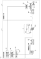
- FIG. 1 is a block diagram showing a configuration of a defect inspection device for a winding according to a first embodiment
- 1A to 1C are diagrams illustrating the principle of detecting defects in a winding using ions.
- 4 is a diagram showing an output of a microammeter of the winding defect inspection device according to the first embodiment, an output of an inspection signal processing means, and an output of a defect presence/absence determining means.
- FIG. 2 is a diagram showing an example of a circuit configuration of an inspection signal processing means and a defect presence/absence determining means according to the first embodiment;
- FIG. FIG. 11 is a block diagram showing the configuration of a winding defect inspection device according to a second embodiment.
- FIG. 11 is a block diagram showing the configuration of a winding defect inspection device according to a third embodiment.
- FIG. 13 is a block diagram showing the configuration of a winding defect inspection device according to a fourth embodiment.
- 13 is a diagram showing the relationship between a motor coil wound around a core, an ion generating means, and an encoder when detecting defects in a winding defect inspection system according to embodiment 5.
- FIG. 13 is a diagram for explaining the relationship of distances for calculating the defect position in the defect detection of a winding defect inspection system according to embodiment 5.
- FIG. FIG. 13 is a flow diagram illustrating a measurement procedure of a defect inspection system according to a fifth embodiment.
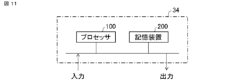
- FIG. 13 is a diagram illustrating an example of a hardware configuration of a controller of a defect inspection system according to a fifth embodiment.
- Embodiment 1. 1 is a block diagram of a defect inspection device for windings of a rotating electrical machine according to embodiment 1.
- the defect inspection device for a winding 1 includes a winding machine main body 2 for winding a winding 1 around a wound member 22 to manufacture a winding component for a rotating electrical machine, and a defect inspection section 3 for the winding 1.
- the defect presence/absence threshold 32d is selected in advance using a preliminary test or the like.
- a preliminary test for example, (a) a winding determined to be free of defects using a JIS pinhole test and (b) a winding determined to be defective are prepared.
- the defect-free winding (a) is wound using a defect inspection device, and the current measured by the microammeter 31 and the voltage converted from the current are recorded. In this case, since only noise is recorded, a voltage higher than the noise voltage is set as the defect presence/absence threshold 32d so as not to erroneously detect the noise as a defect.
- the voltage applied to the ion generator 42 of the ion generating means 4 is set so that the output of the microammeter 31 when the defective winding (b) is wound using a defect inspection device, i.e., the minimum value of the voltage determined to be defective, is greater than the defect presence/absence threshold 32d.
- the microammeter 31 may be any type capable of detecting a microcurrent and converting it into a voltage.
- a commercially available microammeter 5450 may be used.
- the terminal 311 of the microammeter 31 does not output a voltage.
- the voltage of the terminal 311 may be set to 0 V, so that the electric charge 441 naturally flows to the earth.
- the terminal 311 may output a positive voltage of, for example, 50 V to actively draw the charge 441 into the microammeter 31. This increases the amount of charge 441 flowing through the microammeter 31, thereby increasing the detection signal and improving the detection accuracy.
- FIG 4 shows an example of the circuits of the inspection signal processing means 32 and the defect presence/absence determination means 33.
- the inspection signal processing means 32 uses an amplifier 321 (generally called an amplifier; surrounding components other than resistors are omitted) for signal amplification processing to amplify the voltage signal output from the signal converted to voltage by the microammeter 31.
- the defect presence/absence determination means 33 uses a comparator 331 (surrounding components are omitted) to compare the output of the amplifier 321 with the defect presence/absence threshold 32d. If the output of the amplifier 321 is greater than the defect presence/absence threshold 32d, the comparator 331 goes to high level "H" and outputs a signal of, for example, 5V.
- the comparator 331 goes to low level "L” and outputs a signal of, for example, 0V.
- the output of the comparator 331 is shown in Figure 3(c).
- a filter e.g., a low-pass filter may be placed between the amplifier 321 and the comparator 331 to remove noise from the current detected by the microammeter 31.
- Embodiment 2. 5 is a block diagram showing a defect inspection device for a winding of a rotating electrical machine according to embodiment 2.
- the same reference numerals as in FIG. 1 indicate the same or corresponding parts.
- the defect inspection section 3 is mainly composed of the following (1) to (4), and detects defects 13 in the winding 1 while preventing damage to the insulating layer 12 of the winding 1 during detection.
- the winding 1 wound around the unwinding section 21 runs while being given a constant tension by the tensioner 90, and the ion generating means 4a is disposed midway along the path leading to the wound member 22.
- the microammeter 31 detects a current 45 that flows through the winding 1 due to ions generated by the ion generating means 4a when the winding 1 has a defect such as a pinhole.
- the inspection signal processing means 32 amplifies the output of the microammeter 31 and performs noise processing.
- the defect presence/absence determining means 33 determines the presence/absence of a defect based on the output of the inspection signal processing means 32.
- the ion generating means 4a according to the second embodiment is composed of a discharge needle 43, an ion generator 42 which generates a corona discharge in the discharge needle 43, and a power supply 41 which applies a voltage to the ion generator 42, as in the first embodiment. Furthermore, the ion generating means 4a according to the second embodiment has a shielding box 46 made of a non-conductive material for limiting the generation range of the ions 44. The shielding box 46 is formed so as to extend from the ion generator 42 in the direction of the winding 1 so as to surround the discharge needle 43, and may have a cylindrical or rectangular structure.
- a through hole 461 for passing the winding 1 is formed in the shielding box 46, and a lid 462 for confining the ions 44 in the shielding box 46 is provided.
- the concentration of ions 44 can be increased, so that even if the amount of generated ions 44 is the same as in embodiment 1, the charge entering copper core 11 from defect 13 in winding 1 can be increased. This increases the signal detected by microammeter 31. Therefore, for example, even a small defect that cannot be detected by embodiment 1 can be detected by microammeter 31.
- the generation range of ions 44 is limited, there is an advantage that when defect 13 is detected, the position of defect 13 can be more easily identified from the detection time, the running speed of winding 1, and the width of shielding box 46, compared to embodiment 1.
- the shielding box 46 is provided with a lid 462, the lid 462 may be omitted if the ions 44 can be contained within the shielding box 46.
- the defect inspection device of embodiment 2 is provided with a shielding box that limits the range in which ions are generated, thereby improving the accuracy of defect detection and making it easier to identify the detection position of the defect.
- Embodiment 3. 6 is a block diagram showing a defect inspection device for a winding of a rotating electrical machine according to embodiment 3.
- the same reference numerals as in FIG. 1 indicate the same or corresponding parts.
- the defect inspection section 3 is mainly composed of the following (1) to (4), and detects defects 13 in the winding 1 while preventing damage to the insulating layer 12 of the winding 1 during detection.
- the winding 1 wound around the unwinding section 21 runs while being given a constant tension by the tensioner 90, and the ion generating means 4b is disposed midway along the path leading to the wound member 22.
- the microammeter 31 detects a current 45 that flows through the winding 1 due to ions generated by the ion generating means 4b when the winding 1 has a defect such as a pinhole.
- the inspection signal processing means 32 amplifies the output of the microammeter 31 and performs noise processing.
- the defect presence/absence determining means 33 determines the presence/absence of a defect based on the output of the inspection signal processing means 32.
- the ion generating means 4b according to the third embodiment is composed of a discharge needle 43, an ion generator 42 that generates a corona discharge at the discharge needle 43, and a power supply 41 that applies a voltage to the ion generator 42. Furthermore, the ion generating means 4b according to the third embodiment has, between the discharge needle 43 and the winding 1, a metal plate 47 that collects ions 44, a brush 49 that contacts the winding 1, and a conductor 48 that causes electric charge 441 of the ions 44 collected on the metal plate 47 to flow to the brush 49.
- the ions 44 By providing the metal plate 47, the ions 44 actively move toward the metal plate 47, and the ions 44 gather on the metal plate 47, which increases the amount of charge 441 that enters the defect 13 in the winding 1 via the conductor 48 and the brush 49. This increases the signal detected by the microammeter 31, improving the accuracy of detecting minute defects without destroying the insulating layer 12 of the winding 1.
- the generation range of the ions 44 is limited to the contact area between the brush 49 and the winding 1, when a defect 13 is detected, the position of the defect 13 can be more easily identified from the detection time, the running speed of the winding 1, and the width of the brush 49, compared to the first embodiment.
- defects can be detected regardless of the direction in which the discharge needle 43 faces the winding 1.
- the maximum amount of charge 441 flowing through the defect 13 is about 20 ⁇ A, so the insulating layer 12 of the winding 1 is not destroyed. Also, because a high voltage is not applied to the winding 1, discharge between the defect 13 in the winding 1 and a component of the winding machine main body 2, such as the nozzle 23, can be avoided.
- the defect inspection device of embodiment 3 can further improve the defect detection accuracy and also makes it easier to identify the defect detection position.
- Embodiment 4. 7 is a block diagram showing a defect location inspection device for a winding of a rotating electrical machine according to embodiment 4.
- the same reference numerals as those in FIG. 1 are identical to FIG. 1 and the same reference numerals as those in FIG. 1;
- embodiment 4 The difference between embodiment 4 and embodiment 1 is that, as described above, two ion generating means 4a1, 4a2 are arranged at different positions along the running direction of the winding 1 to surround the outer periphery of the winding 1.
- the operation of the defect inspection device for winding 1 according to embodiment 4 is the same as that described in embodiments 1 and 2, except that defects 13 are detected by ions 44 that surround the outer periphery of the winding 1 by ion generating means 4a2 in addition to ion generating means 4a1.
- the operation of inspecting the winding 1 for defects will now be described.
- the ion generating means 4a1 and 4a2 are placed, for example, at a distance of 10 cm.
- the running speed of the winding 1 is assumed to be 500 mm/s.
- the defect 13 in the winding 1 passes through the shielding box 46 of the ion generating means 4a1 and then passes through the shielding box 46 of the ion generating means 4a2 0.2 seconds later, so that the microammeter 31 detects the signal 45a or signal 45b shown in FIG. 3 twice, and the detection time difference is also 0.2 seconds.
- controller 34 calculates the time difference between the two detected defect presence/absence signals 33a or defect presence/absence signals 33b (for example, the time difference between the rise of the defect presence/absence signal), and if the time difference is 0.2 seconds, it is determined that there is a defect 13 in winding 1.
- the operator may be alerted by, for example, emitting a warning sound or displaying a message on the display, or other measures may be taken, such as stopping winding machine main body 2 to remove or repair the defective portion.
- the time difference is not 0.2 seconds, it is determined that the microammeter 31 has detected noise, and that there is no defect 13 in the winding 1.
- two ion generating means 4a1 and 4a2 are described, but two or more ion generating means may be arranged along the running direction of winding 1. In this case, the result of the plurality of defect presence/absence signals may be judged by a majority circuit or the like.
- the configuration of the ion generating means 4a1 and 4a2 in this embodiment may be the same as that of the ion generating means 4b shown in the third embodiment.
- the defect inspection device of embodiment 4 uses multiple ion generating means to detect the same defect in the winding 1, thereby further increasing the probability and accuracy of defect detection.
- FIG. 8(a) is a diagram showing the relationship between the motor coil 5 wound around the core 6, the ion generating means 4, and the encoder E in defect detection.
- the winding 1 is wound as the motor coil 5 when the teeth of the core 6 are viewed in the protruding direction toward the core back part.
- the coil distance T1 is the length along the circumferential direction of the motor
- the coil distance T2 is the length along the axial direction of the motor.
- FIG. 8(b) is a perspective view showing the state in which the winding 1 is wound around the insulator 7 of the core 6 as the motor coil 5.
- the winding as the motor coil 5 is performed by rotating a spindle to which the core 6 is attached.
- the distance L 1 from the discharge needle 43 of the ion generating means 4 to the tip of the nozzle 23, the distance L 2 from the tip of the nozzle 23 to the motor coil 5, the distance T 1 in the short direction of the motor coil 5, the distance T 2 in the long direction, and the elongation rate of the winding 1 under winding tension are previously determined.
- An encoder E is placed between the discharge needle 43 and the nozzle 23, and the distance (length) is measured from the speed at which the winding 1 passes the encoder E.
- the controller 34 receives the signal from the defect presence/absence determination means 33 and the signal from the encoder E, and records the winding distance up to and after the defect is detected, with the start of winding the motor coil 5 being set as the zero point. This makes it possible to calculate and identify which turn and where on the motor coil 5 the defect is located by executing the measurement procedure flow from the winding distance data from the encoder E, the known distances L1 , L2, T1 , T2 , and the elongation rate of the winding 1 under the winding tension.
- step S1 When winding is started by the winding machine main body 2, counting of the distance of the encoder E is started at the same time (step S1).
- step S2 the distance E1 counted at the time of detection is obtained and stored in the controller 34 (step S3).
- step S4 At the same time as obtaining the distance E1 , a new count is started to obtain the distance E2 (step S4).
- the total distance Rtotal of the winding 1 required to complete winding is compared with the distance E1 at which the defect was detected (step S5).
- the known distances L1 and L2 at the start of winding are added to the distance E1 (see the relationship of each distance in Figure 10).
- step S5 When distance E1 + distance L1 + distance L2 is smaller than the total distance Rtotal (YES in step S5), the defect position on the motor coil 5 according to distance E1 + distance L1 + distance L2 is calculated and recorded in the controller 34 (step S6). Distance E2 from when the defect was detected to the present is added to distance E1 at which the defect was detected to determine distance E1 from the start of winding to the present (step S7), and the count of distance E1 is continued. In this case, distance E2 is reset (step S8).
- step S5 When distance E1 + distance L1 + distance L2 is equal to or greater than total distance Rtotal (No in step S5), it is assumed that a defect has occurred somewhere in the range from the end of winding to a point that is distance L1 + distance L2 back, and the work is replaced (step S10), and the defect position on motor coil 5 corresponding to distance L1 + distance L2 - distance E2 is calculated (see the relationship of each distance in FIG. 10) and recorded in controller 34 (step S11). After recording, counted distances E1 and E2 are reset (step S12).
- This measurement flow makes it possible to accurately determine the location of defects on the wound motor coil 5. For example, in the case of a one-tooth core motor, by removing only the defective teeth in advance, it is possible to reduce the rate of defects in later processes and reduce overall costs. In addition, even if a motor coil has a defect, by arranging the defective motor coils so that they are not adjacent to each other when assembling the stator, it is possible to use the motor coil without the defect being an issue, and it is expected to increase yield.
- FIG. 11 An example of the hardware of the controller 34 is shown in FIG. 11. It is composed of a processor 100 and a storage device 200.
- the storage device 200 includes a volatile storage device such as a random access memory and a non-volatile auxiliary storage device such as a flash memory.
- a hard disk auxiliary storage device may be included.
- the processor 100 executes a program input from the storage device 200 to execute the measurement flow shown in FIG. 9, for example. In this case, the program is input from the auxiliary storage device to the processor 100 via the volatile storage device.
- the processor 100 may output data such as the measured values and the calculated defect positions to the volatile storage device of the storage device 200, or may store the data in the auxiliary storage device via the volatile storage device.
Landscapes
- Physics & Mathematics (AREA)
- General Physics & Mathematics (AREA)
- Engineering & Computer Science (AREA)
- Power Engineering (AREA)
- Manufacturing & Machinery (AREA)
- Testing Of Short-Circuits, Discontinuities, Leakage, Or Incorrect Line Connections (AREA)
Priority Applications (1)
| Application Number | Priority Date | Filing Date | Title |
|---|---|---|---|
| JP2025550764A JPWO2025074707A1 (https=) | 2023-10-05 | 2024-07-17 |
Applications Claiming Priority (2)
| Application Number | Priority Date | Filing Date | Title |
|---|---|---|---|
| JP2023-173439 | 2023-10-05 | ||
| JP2023173439 | 2023-10-05 |
Publications (1)
| Publication Number | Publication Date |
|---|---|
| WO2025074707A1 true WO2025074707A1 (ja) | 2025-04-10 |
Family
ID=95282951
Family Applications (1)
| Application Number | Title | Priority Date | Filing Date |
|---|---|---|---|
| PCT/JP2024/025561 Pending WO2025074707A1 (ja) | 2023-10-05 | 2024-07-17 | 巻線の欠陥検査装置、巻線の欠陥検査システムおよび巻線の欠陥検査方法 |
Country Status (2)
| Country | Link |
|---|---|
| JP (1) | JPWO2025074707A1 (https=) |
| WO (1) | WO2025074707A1 (https=) |
Citations (9)
| Publication number | Priority date | Publication date | Assignee | Title |
|---|---|---|---|---|
| US3096478A (en) * | 1959-08-18 | 1963-07-02 | Okonite Co | Apparatus with conductive gas electrodes for detecting non-uniformity in electrically insulating and electrically semi-conducting materials |
| JPH04249778A (ja) * | 1990-01-05 | 1992-09-04 | Westinghouse Electric Corp <We> | 電気ケーブル監視装置 |
| JPH0618604A (ja) * | 1992-06-29 | 1994-01-28 | Hitachi Cable Ltd | 電力ケーブルの絶縁劣化診断方法および欠陥検出方法 |
| JP2000340925A (ja) * | 1999-05-31 | 2000-12-08 | Micro Craft Kk | プリント配線基板検査装置 |
| JP2010170919A (ja) * | 2009-01-26 | 2010-08-05 | Rb Controls Co | イオン発生装置の検査用治具 |
| CN102053106A (zh) * | 2009-11-09 | 2011-05-11 | 中芯国际集成电路制造(上海)有限公司 | 一种缺陷检测方法 |
| JP2022161713A (ja) * | 2021-04-09 | 2022-10-21 | 株式会社日立製作所 | 絶縁劣化診断モデル作成装置、絶縁劣化診断装置、及び絶縁劣化診断方法 |
| WO2023063078A1 (ja) * | 2021-10-13 | 2023-04-20 | 三菱電機株式会社 | 巻線欠陥検査装置、巻線欠陥検査装置を使用した電気機械の製造方法、及び巻線欠陥検査方法 |
| WO2023171570A1 (ja) * | 2022-03-08 | 2023-09-14 | 三菱電機株式会社 | コイル製造装置、コイル製造方法、ステーター製造方法および回転電機製造方法 |
-
2024
- 2024-07-17 WO PCT/JP2024/025561 patent/WO2025074707A1/ja active Pending
- 2024-07-17 JP JP2025550764A patent/JPWO2025074707A1/ja active Pending
Patent Citations (9)
| Publication number | Priority date | Publication date | Assignee | Title |
|---|---|---|---|---|
| US3096478A (en) * | 1959-08-18 | 1963-07-02 | Okonite Co | Apparatus with conductive gas electrodes for detecting non-uniformity in electrically insulating and electrically semi-conducting materials |
| JPH04249778A (ja) * | 1990-01-05 | 1992-09-04 | Westinghouse Electric Corp <We> | 電気ケーブル監視装置 |
| JPH0618604A (ja) * | 1992-06-29 | 1994-01-28 | Hitachi Cable Ltd | 電力ケーブルの絶縁劣化診断方法および欠陥検出方法 |
| JP2000340925A (ja) * | 1999-05-31 | 2000-12-08 | Micro Craft Kk | プリント配線基板検査装置 |
| JP2010170919A (ja) * | 2009-01-26 | 2010-08-05 | Rb Controls Co | イオン発生装置の検査用治具 |
| CN102053106A (zh) * | 2009-11-09 | 2011-05-11 | 中芯国际集成电路制造(上海)有限公司 | 一种缺陷检测方法 |
| JP2022161713A (ja) * | 2021-04-09 | 2022-10-21 | 株式会社日立製作所 | 絶縁劣化診断モデル作成装置、絶縁劣化診断装置、及び絶縁劣化診断方法 |
| WO2023063078A1 (ja) * | 2021-10-13 | 2023-04-20 | 三菱電機株式会社 | 巻線欠陥検査装置、巻線欠陥検査装置を使用した電気機械の製造方法、及び巻線欠陥検査方法 |
| WO2023171570A1 (ja) * | 2022-03-08 | 2023-09-14 | 三菱電機株式会社 | コイル製造装置、コイル製造方法、ステーター製造方法および回転電機製造方法 |
Also Published As
| Publication number | Publication date |
|---|---|
| JPWO2025074707A1 (https=) | 2025-04-10 |
Similar Documents
| Publication | Publication Date | Title |
|---|---|---|
| JP4471628B2 (ja) | 発電機界磁巻線の速度感知界磁地絡検出モード | |
| JP2018112452A (ja) | 部分放電監視装置および部分放電監視方法 | |
| WO2025074707A1 (ja) | 巻線の欠陥検査装置、巻線の欠陥検査システムおよび巻線の欠陥検査方法 | |
| JPWO2015029151A1 (ja) | 部分放電計測法およびそれを用いて検査した高電圧機器 | |
| JP5120133B2 (ja) | 磁界測定による部分放電検出方法 | |
| WO2016170588A1 (ja) | 磁界測定システムおよびこれを用いた故障診断システム | |
| KR100705121B1 (ko) | 소형 전기 기계의 비파괴 절연 시험 방법 및 장치 | |
| JP7374348B2 (ja) | 被覆欠陥検出装置と被覆欠陥検出方法、および回転電機の製造方法 | |
| JP4057182B2 (ja) | 部分放電判定方法 | |
| JP2024141116A (ja) | 巻線の欠陥検査装置 | |
| JP2585593B2 (ja) | 半導体装置の静電気検出装置 | |
| Gräf et al. | Nonconventional partial discharge measurement using fiber optic sensor system for transmission systems and switchgear | |
| CN103314302A (zh) | 增强旋转电机上的发电机接地故障检测的可靠性的方法和设备 | |
| JP2024138932A (ja) | 巻線の欠陥検査装置 | |
| US20230176105A1 (en) | Insulation defect detection method and detection system for magnet wire coating, manufacturing method for electric machine, and electric machine | |
| JP6018011B2 (ja) | 回転電機の絶縁検査装置 | |
| JP3083163B2 (ja) | ケーブル絶縁体の欠陥部検出方法 | |
| JPH03150474A (ja) | 除電装置の検査器 | |
| TWI914969B (zh) | 荷電粒子束裝置 | |
| JP2011252779A (ja) | 磁界プローブを用いた電気機器の部分放電検出方法 | |
| JP2006107778A (ja) | 除電装置 | |
| TW202529142A (zh) | 荷電粒子束裝置 | |
| JPH0618605A (ja) | 高分子絶縁電力ケーブルの欠陥検出法 | |
| JPWO2025074707A5 (https=) | ||
| WO2024203017A1 (ja) | 巻線の欠陥検査装置 |
Legal Events
| Date | Code | Title | Description |
|---|---|---|---|
| 121 | Ep: the epo has been informed by wipo that ep was designated in this application |
Ref document number: 24874323 Country of ref document: EP Kind code of ref document: A1 |
|
| ENP | Entry into the national phase |
Ref document number: 2025550764 Country of ref document: JP Kind code of ref document: A |
|
| WWE | Wipo information: entry into national phase |
Ref document number: 2025550764 Country of ref document: JP |