WO2025070016A1 - 歯ブラシ - Google Patents
歯ブラシ Download PDFInfo
- Publication number
- WO2025070016A1 WO2025070016A1 PCT/JP2024/032194 JP2024032194W WO2025070016A1 WO 2025070016 A1 WO2025070016 A1 WO 2025070016A1 JP 2024032194 W JP2024032194 W JP 2024032194W WO 2025070016 A1 WO2025070016 A1 WO 2025070016A1
- Authority
- WO
- WIPO (PCT)
- Prior art keywords
- filament
- neck
- toothbrush
- neck portion
- thickness direction
- Prior art date
- Legal status (The legal status is an assumption and is not a legal conclusion. Google has not performed a legal analysis and makes no representation as to the accuracy of the status listed.)
- Pending
Links
Images






Classifications
-
- A—HUMAN NECESSITIES
- A46—BRUSHWARE
- A46B—BRUSHES
- A46B3/00—Brushes characterised by the way in which the bristles are fixed or joined in or on the brush body or carrier
- A46B3/04—Brushes characterised by the way in which the bristles are fixed or joined in or on the brush body or carrier by mouldable materials, e.g. metals, cellulose derivatives, plastics
-
- A—HUMAN NECESSITIES
- A46—BRUSHWARE
- A46B—BRUSHES
- A46B9/00—Arrangements of the bristles in the brush body
- A46B9/02—Position or arrangement of bristles in relation to surface of the brush body, e.g. inclined, in rows, in groups
- A46B9/04—Arranged like in or for toothbrushes
Definitions
- the present invention relates to a toothbrush.
- This application claims priority based on Japanese Patent Application No. 2023-162902, filed on September 26, 2023, the contents of which are incorporated herein by reference.
- Integrated toothbrushes with filaments made of soft resin have been proposed (see, for example, Patent Document 1). Because the filaments in such toothbrushes are flexible, they tend to provide a gentler feel than toothbrushes whose bristles are made of spun bristles.
- the brush part is molded from a soft resin, so the volume of the hard resin that constitutes the head part is smaller than in toothbrushes whose bristles are formed from spun bristles.
- the width of the head part and the neck part are generally widened to increase the rigidity from the head part to the neck part, thereby suppressing deformation of the head part.
- the brushing load is concentrated on the filament, and the filament may bend too much. In this case, the filament has difficulty penetrating between the teeth, and the cleaning performance between the teeth is reduced.
- the rigidity of the neck part is made too small, the bending of the neck part becomes too large, and the operability of the head part in the oral cavity is reduced. This reduces the operability of the toothbrush.
- the movement of the tip of the filament is difficult to link with the movement of the user's hand during brushing, which affects the cleaning performance between the teeth.
- the present invention was made in consideration of the above points, and one of its objectives is to provide a toothbrush that can improve interdental cleaning performance while preventing a decrease in the operability of the toothbrush.
- a brush comprising a handle body formed of hard resin and extending in a longitudinal direction, and a brush portion formed of soft resin and arranged on one side of the handle body in the longitudinal direction, wherein the brush portion has a brush base portion and a plurality of filaments molded integrally with the brush base portion, each of the plurality of filaments protruding from the brush base portion toward one side in a thickness direction intersecting the longitudinal direction, and the handle body has a neck portion extending in the longitudinal direction, a connection portion protruding from the neck portion to one side in the longitudinal direction, a fitting portion protruding from the connection portion to one side in the longitudinal direction, a connection edge portion that is a part of the connection portion, and a neck edge portion that is a part of the neck portion, and wherein the connection portion, the fitting portion, and and the brush base portion constitute a head shaft portion, the connecting edge portion is an end portion on one side in the longitudinal direction of the connecting portion and an end portion on one side in
- the neck portion has a first neck portion, a second neck portion, and a third neck portion, and a distance in the long axis direction between a connection tip portion, which is an end portion on one side in the long axis direction of the connection portion, and an end portion on the other side in the long axis direction of the neck portion is a first distance L1
- a ratio of the distance between the connection tip portion and the first neck portion to the first distance in the long axis direction is 20%
- a ratio of the distance between the connection tip portion and the second neck portion to the first distance in the long axis direction is 80%
- a ratio of the distance between the connection tip portion and the third neck portion to the first distance in the long axis direction is 100%
- a dimension in the width direction of the first neck portion is W1
- a dimension in the thickness direction of the first neck portion is T1
- a dimension in the width direction of the second neck portion is W2
- a dimension in the thickness direction of the second neck portion is T2
- each of the multiple filaments has a first filament portion and a second filament portion, and when viewed in the width direction, the amount of reduction in the dimension in the major axis direction per unit length in the thickness direction of each of the multiple filaments gradually increases from the brush base portion toward one side in the thickness direction, and in the thickness direction, the ratio of the distance between the end of the filament on one side in the thickness direction and the first filament portion to the dimension of the filament is 15%, the second filament portion is a portion connected to the brush base, and the ratio of the area of the cross section perpendicular to the thickness direction of the first filament portion to the area of the cross section perpendicular to the thickness direction of the second filament portion is 20% or more and 30% or less.
- a first average value RF1ave which is the average value of the first reaction force fluctuation rate within a range in which the movement distance of the pressure member is 3.0 mm or less, is 0.5 N/mm or more and 1.0 N/mm or less.
- the present invention provides a toothbrush that can improve interdental cleaning performance while preventing a decrease in the operability of the toothbrush.
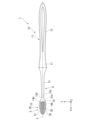
- FIG. 2 is a front view showing the toothbrush of the embodiment.
- FIG. 2 is a side view showing the toothbrush of the embodiment.
- FIG. 2 is a front view showing the handle body of the embodiment.
- FIG. 2 is a side view showing the handle body of the embodiment.
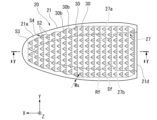
- FIG. 2 is a front view showing the brush unit of the embodiment.
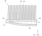
- 6 is a cross-sectional view showing the brush part of the embodiment, taken along line VI-VI in FIG. 5 .
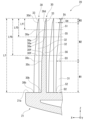
- FIG. 3 is a cross-sectional view showing a part of the brush unit of the embodiment.
- FIG. 2 is a diagram showing a part of a toothbrush according to an embodiment.
- FIG. 2 is a front view showing a portion of the toothbrush according to the embodiment.
- FIG. 2 is a side view showing the first deflection testing device.
- FIG. 11 is a diagram illustrating an example of a first reaction force according to the embodiment.
- FIG. 11 is a diagram showing a method for calculating a first reaction force variation rate in the embodiment.
- FIG. 4 is a diagram illustrating an example of a first reaction force fluctuation rate according to the embodiment.
- FIG. 13 is a side view showing a second deflection testing device.
- FIG. 11 is a diagram illustrating an example of a second pressure according to the embodiment.
- FIG. 11 is a diagram illustrating an example of a second pressure change rate according to the embodiment.
- FIG. 11 is a graph showing a first reaction force variation rate in a first deflection test.
- FIG. 13 is a graph showing a second pressure fluctuation rate in a second deflection test.
- an XYZ coordinate system is shown as a three-dimensional orthogonal coordinate system.
- the X-axis direction is the long axis direction.
- the long axis direction is the direction in which the toothbrush extends.
- the +X side is the tip side of the toothbrush
- the -X side is the rear end side of the toothbrush.
- the tip side of the toothbrush will be simply referred to as the "tip side” or "one side in the long axis direction”
- the rear end side of the toothbrush will be simply referred to as the "rear end side” or "the other side in the long axis direction.”
- the Z-axis direction intersects with the X-axis direction and is the thickness direction of the toothbrush.
- the Z-axis direction is perpendicular to the X-axis direction.
- the +Z side is the front side of the toothbrush, and the -Z side is the back side of the toothbrush.
- the front side of the toothbrush will be simply referred to as the "front side” or “one side in the thickness direction”
- the back side of the toothbrush will be simply referred to as the "back side” or "the other side in the thickness direction.”
- the Y-axis direction is a direction that intersects both the X-axis direction and the Z-axis direction, and is the width direction of the toothbrush.
- the Y-axis direction is perpendicular to both the X-axis direction and the Z-axis direction.
- the +Y side is one side in the width direction of the toothbrush
- the -Y side is the other side in the width direction of the toothbrush.
- one side in the width direction of the toothbrush will be simply referred to as “one side in the width direction”
- the other side in the width direction of the toothbrush will be simply referred to as “the other side in the width direction”.
- the dimension of a component in its long axis direction may be simply referred to as "length”.
- the dimension of a component in its width direction may be simply referred to as “width”.
- the dimension of a component in its thickness direction may be simply referred to as "thickness”.
- Viewing an object from the front may be referred to as "front view”, and the shape of an object viewed from the front may be referred to as “front view shape”.
- Viewing an object from the width direction may be referred to as "side view”, and the shape of an object viewed from the width direction may be referred to as "side view shape”.
- FIG. 1 is a front view of the toothbrush 1 of this embodiment.
- FIG. 2 is a side view of the toothbrush 1 of this embodiment.
- the toothbrush 1 includes a handle body 10 and a brush section 20.
- the handle body 10 and the brush section 20 are separate members.
- the handle body 10 and the brush section 20 are made of resin.
- the handle body 10 is rod-shaped and extends in the longitudinal direction.
- the brush section 20 is located on the tip side of the handle body 10, i.e., on one side (+X side) in the longitudinal direction.
- FIG. 3 is a front view showing the handle body 10 of this embodiment.
- FIG. 4 is a side view showing the handle body 10 of this embodiment.
- the handle body 10 has a rod-shaped handle main body 11 extending in the longitudinal direction, a fitting portion 15 that protrudes from the tip of the handle main body 11 toward the tip side, i.e., one side in the longitudinal direction (+X side), and a fitting edge portion 15d.
- the brush part 20 is attached to the handle body 10 by fitting the fitting portion 15 into a fitting hole 27 of the brush part 20 described below.
- the length of the handle body 10 is, for example, 100 mm or more and 200 mm or less.
- the handle body 10 is made of a hard resin.
- hard resins that form the handle body 10 include resins with a flexural modulus (JIS K7171) of 1500 MPa or more and 3000 MPa or less.
- Specific examples include polypropylene resin (PP), polybutylene terephthalate resin (PBT), polyacetal resin (POM), polyester resin (PCTA), polyethylene terephthalate copolymer (PETG), and high density polyethylene (HDPE).
- polypropylene resin which is a general-purpose resin, is preferred in terms of manufacturing costs
- polybutylene terephthalate resin and polyacetal resin are preferred in terms of strength.
- the shape of the handle body 11 in this embodiment in front view gradually narrows from the tip side to the rear end side until it reaches the first boundary 13a, and then gradually widens when it reaches the first boundary 13a, and then reaches the second boundary 13b. After that, the width gradually narrows, then widens, and then narrows.
- the shape of the rear end of the handle body 11 in front view is approximately semicircular. Note that, when the shape of the handle body 11 in front view gradually narrows from the tip side to the rear end side, and then extends in the longitudinal direction with the same width, the first boundary 13a is the tip of the part that extends in the longitudinal direction with the same width.
- the shape of the handle body 11 in front view is a plane-symmetric shape with a plane that passes through the central axis J and extends in a direction perpendicular to the width direction as a plane of symmetry.
- the side view shape of the handle body 11 in this embodiment gradually becomes thinner from the tip side to the rear end side, then reaches the first boundary 13a, then changes to a curved shape so that the thickness gradually increases until it reaches the second boundary 13b, at which point it gradually becomes thinner, then changes to a curved shape so that it extends at an approximately constant thickness, and then changes to a thinner thickness.
- the side view shape of the rear end of the handle body 11 is approximately semicircular.
- the second boundary 13b is the portion that connects the first upper edge 11a, whose front side (+Z side) edge is curved upward as it moves from the tip side to the rear end, and the second upper edge 11b, whose front side edge is curved downward as it moves from the tip side to the rear end.
- the center of curvature of the first upper edge 11a and the center of curvature of the second upper edge 11b are both located above the handle body 11.
- the second boundary 13b is the portion of the handle body 11 where the apex of the convex shape that protrudes toward the front side is formed.
- the second boundary 13b is the portion where the center of curvature of the edge on the front side (+Z side) of the handle body 11 changes. If the portion where the center of curvature of the edge on the front side of the handle body 11 changes cannot be identified, the second boundary 13b is the portion where the hard resin and the soft resin come into contact in the longitudinal direction. Furthermore, if the portion where the hard resin and the soft resin come into contact in the longitudinal direction cannot be identified, the second boundary 13b is the portion 73 mm rearward from the tip of the head portion 5 described below. In this embodiment, the tip of the head portion 5 is the tip of the brush portion 20.
- the shape of the handle body 11 is not limited to the shape of this embodiment, and can be set appropriately taking into consideration strength, operability, design, etc.
- the dimensions of the handle body 11 are not particularly limited, and can be set appropriately.
- the handle body 11 has a grip portion 12, a neck portion 13, a connection portion 14, a neck edge portion 13d, and a connection edge portion 14d.
- the grip portion 12 is the portion of the handle body 11 that is rearward of the second boundary portion 13b.
- the grip portion 12 is rod-shaped and extends in the longitudinal direction.
- a finger rest portion 17 is provided on the outer surface of the grip portion 12.
- the finger rest portion 17 is made of soft resin.
- Various elastomers such as polyurethane-based and styrene-based elastomers can be used as the soft resin that forms the finger rest portion 17.
- the user can improve the grip of the toothbrush 1 by placing their fingers on the finger rest portion 17 while holding the grip portion 12.
- the neck portion 13 is the portion of the handle body 11 between the first boundary portion 13a and the second boundary portion 13b.
- the neck portion 13 is rod-shaped and extends in the longitudinal direction.
- the second boundary portion 13b is the boundary between the neck portion 13 and the grip portion 12. The shape of the neck portion 13 will be described in detail later.
- connection part 14 is a part of the handle body 11 that is closer to the tip side than the first boundary part 13a.
- the first boundary part 13a is the boundary between the connection part 14 and the neck part 13.
- the connection part 14 protrudes from the neck part 13 toward the tip side, that is, toward one side (+X side) in the longitudinal direction.
- the connection part 14 connects the neck part 13 and the fitting part 15.
- the width of the connection part 14 is widest at the tip, changes in a curved shape so as to gradually narrow toward the rear end, and is narrowest at the rear end. As shown in FIG. 4, the thickness of the connection part 14 is thickest at the tip, gradually thins toward the rear end, and is thinnest at the rear end.
- the connection part 14 has a first opposing surface 14b.
- the first opposing surface 14b is the surface of the outer surface of the connection part 14 that faces the tip side.
- connection edge 14d is a part of the connection part 14.
- the connection edge 14d is the tip of the connection part 14, i.e., the end part on one side in the longitudinal direction (+X side) and the end part on one side in the width direction (+Y side).
- the connection edge 14d is the part of the connection part 14 located closest to one side in the width direction.
- the connection edge 14d is located on one side in the width direction of the first boundary part 13a.
- the fitting part 15 is located inside the brush part 20. As shown in FIG. 3 and FIG. 4, the fitting part 15 protrudes from the first opposing surface 14b of the connection part 14 toward the tip side. As shown in FIG. 3, the fitting part 15 is provided with a pair of recesses 15a, 15b. One recess 15a is recessed from a surface facing one side in the width direction of the fitting part 15 (+Y side) to the other side in the width direction (-Y side). The other recess 15b is recessed from a surface facing the other side in the width direction of the fitting part 15 to one side in the width direction. Each of the pair of recesses 15a, 15b is approximately semicircular in front view.
- the mating edge 15d is the rear end of the mating portion 15, i.e., the end on the other side (-X side) in the longitudinal direction and the end on one side (+Y side) in the width direction.
- the mating edge 15d is located on one side in the width direction from the first boundary portion 13a.
- the mating edge 15d is located on the other side in the width direction (-Y side) from the connection edge 14d. Note that even if a through hole is present in the mating portion 15, the mating portion 15 still exists, and in this case, the hard resin portion covered with the soft resin is the mating portion.
- FIG. 5 is a front view showing the brush part 20 of this embodiment.
- FIG. 6 is a cross-sectional view showing the brush part 20 of this embodiment, taken along the line VI-VI in FIG. 5.
- FIG. 7 is a cross-sectional view showing a part of the brush part 20 of this embodiment.
- the brush part 20 is made of soft resin.
- the brush part 20 has a brush base part 21 and a plurality of filaments 30 molded integrally with the brush base part 21.
- the brush part 20 is molded by insert molding using the handle body 10, which is made of hard resin, as an insert member.
- the toothbrush 1 of this embodiment is an integrally molded toothbrush in which the brush part 20 and the handle body 10 are molded integrally.
- the toothbrush 1 of this embodiment is an integrally molded toothbrush in which the filaments 30 are made of soft resin.
- the shape of the brush base 21 in this embodiment when viewed from the front changes to a curved shape so that its width gradually increases from the tip side to the rear end side.
- the tip of the brush base 21 when viewed from the front is approximately semicircular.
- the shape of the brush base 21 in this embodiment when viewed from the side changes to a shape so that its thickness gradually increases from the tip side to the rear end side. More specifically, the surface facing the rear side (-Z side) of the brush base 21 is located closer to the rear side as it moves from the tip side to the rear end side.
- the upper surface 21a which is the surface facing the front side (+Z side) of the brush base 21, is a flat surface that extends in a direction perpendicular to the thickness direction.
- the outer surface of the brush base portion 21 that faces the rear end is the second opposing surface 21d.
- the second opposing surface 21d is substantially rectangular when viewed from the longitudinal direction. As shown in FIG. 1, when the brush portion 20 is attached to the handle body 10, the second opposing surface 21d faces the first opposing surface 14b of the handle body 10 in the longitudinal direction. In this embodiment, the second opposing surface 21d contacts the first opposing surface 14b in the longitudinal direction.
- the brush base 21 has a fitting hole 27 recessed from the second opposing surface 21d toward the tip.
- a fitting portion 15 is disposed inside the fitting hole 27.
- the surface facing the rear side (-Z side) is a flat surface extending in a direction perpendicular to the thickness direction.
- the surface facing the front side (+Z side) is positioned closer to the rear side as it moves from the tip side to the rear end side.
- the fitting hole 27 is provided with a pair of protrusions 27a, 27b.
- One protrusion 27a protrudes to the other widthwise side from the surface facing the other widthwise side (-Y side) of the fitting hole 27.
- the other protrusion 27b protrudes to one widthwise side from the surface facing the one widthwise side (+Y side) of the fitting hole 27.
- each of the pair of protrusions 27a, 27b is approximately semicircular in shape.
- Each of the pair of protrusions 27a, 27b fits into each of the pair of recesses 15a, 15b.
- each of the filaments 30 protrudes from the top surface 21a of the brush base 21 toward the front side, i.e., toward one side in the thickness direction (+Z side).
- Each filament 30 is made of soft resin.
- FIG. 5 on the top surface 21a, multiple rows made up of multiple filaments 30 aligned along the width direction are arranged side by side in the long axis direction.
- the root of the filament 30 is the end of the filament 30 on the rear side, which is the part that connects to the brush base 21.
- the tip of the filament 30 is the end of the filament 30 on the front side. The shape of the filament 30 will be described in detail later.
- elastomers can be used as the soft resin that makes up the brush portion 20, but polyurethane is preferable. Compared to other elastomers such as styrene-based or polyester-based elastomers, polyurethane has high tensile strength, so it can ensure mechanical strength even when made thin. This helps prevent breakage of the toothbrush 1 when it is in use.
- polyurethane has a wider range of hardness options than the other elastomers, and the resin hardness can be selected taking into account the operability (e.g., bending of the tip of the brush part 20) according to the thickness of the brush part 20.
- the hardness of polyurethane is preferably a Shore hardness of A90 or more and A100 or less, or a Shore hardness of D40 or more and D70 or less. If the polyurethane has a hardness softer than Shore 90A, it is easily deformed when formed with a thin wall, so the fit is weak and the brush part 20 is easily removed when the toothbrush 1 is used.
- the polyurethane has a hardness harder than Shore 70D, and if the back surface of the brush base part 21 is inclined, there is a risk of pain when the tip of the brush base part 21 hits the oral cavity.
- Shore 90A or more and 70D or less it is possible to prevent the brush head 20 from falling off when the toothbrush 1 is in use, and also to prevent pain from occurring when the tip of the brush base 21 hits the oral cavity.
- Polyurethane contains at least 0.01 wt% (mass%) and no more than 1.0 wt% (mass%) of saturated/unsaturated hydrocarbons of C10 or higher, higher alcohols, fatty acid amides, fatty acid esters, low molecular weight polyethylene, polyethylene glycol (PEG), fatty acid metal salts, long-chain fatty acids, fatty acid glycerin, and silicone, or a combination of these, which function as lubricants and release agents.
- PEG polyethylene glycol
- fatty acid metal salts long-chain fatty acids
- fatty acid glycerin glycerin
- silicone silicone
- the toothbrush 1 of this embodiment includes a head portion 5 and a head shaft portion 6.
- the connection portion 14, the fitting portion 15, and the brush portion 20 constitute the head portion 5.
- the head portion 5 is the portion of the toothbrush 1 that is closer to the tip side than the first boundary portion 13a. When the toothbrush 1 is in use, the head portion 5 is located in the oral cavity and is the part that cleans the oral cavity.
- the maximum width of the head portion 5 is preferably 11 mm or less. This improves the maneuverability of the head portion 5 within the oral cavity, thereby improving the cleaning performance within the oral cavity.
- connection portion 14, the fitting portion 15, and the brush base portion 21 constitute the head shaft portion 6.
- the head shaft portion 6 is a part of the head portion 5.
- the head shaft portion 6 is the portion of the head portion 5 excluding the multiple filaments 30.
- the head shaft portion 6 is the portion of the handle body 10 that is closer to the tip side than the first boundary portion 13a.
- Fig. 8 is a diagram showing a part of the toothbrush 1 of this embodiment. More specifically, Fig. 8(a) is a side view showing a part of the toothbrush 1 of this embodiment. Fig. 8(b) is a side view showing a part of the handle body 10 of this embodiment. Fig. 8(c) is a front view showing a part of the handle body 10 of this embodiment.
- the maximum thickness Th of the head shaft 6 shown in FIG. 8B that is, the maximum dimension of the head shaft 6 in the thickness direction, is 3.0 mm or more and 4.5 mm or less.
- the neck portion 13 is the portion of the handle body 10 between the first boundary portion 13a and the second boundary portion 13b.
- the width of the neck portion 13 of this embodiment gradually increases from the first boundary portion 13a toward the second boundary portion 13b.
- the width of the neck portion 13 is narrowest at the first boundary portion 13a and widest at the second boundary portion 13b.
- the thickness of the neck portion 13 of this embodiment extends from the first boundary portion 13a toward the second boundary portion 13b at the same thickness toward the rear end side, then changes linearly to become gradually thicker, and then extends toward the rear end side while changing in a curved manner to become gradually thicker.
- the thickness of the neck portion 13 is thinnest at the first boundary portion 13a and thickest at the second boundary portion 13b.
- FIG. 9 is a front view showing a part of the toothbrush 1 of the present embodiment.
- the neck edge 13d is a part of the neck portion 13.
- the neck edge 13d is an end portion on one side (+Y side) of the first boundary 13a in the width direction.
- the first boundary 13a is the narrowest part of the neck portion 13. Therefore, the neck edge 13d is an end portion on one side of the part of the neck portion 13 with the smallest dimension in the width direction.
- the width Wa of the first boundary 13a i.e., the minimum dimension in the width direction of the neck portion 13, is 3.0 mm or more and 4.5 mm or less.
- the first angle ⁇ 1 which is the angle between the first virtual line V1 and the central axis J when viewed from the thickness direction, is 17° or more and 28° or less.
- the head shaft 6 is bent appropriately, so that stress concentration on each filament 30 can be prevented. Therefore, the part of the toothbrush 1 from each filament 30 to the head shaft 6 bends in conjunction with each other. Therefore, the bending of each filament 30 can be prevented from becoming too large, so that the cleaning performance between teeth can be improved. In addition, the bending of the head shaft 6 can be prevented from becoming too large, so that the operability of the toothbrush 1 can be prevented from decreasing, and the movement of the tip of each filament 30 is easily linked with the movement of the user's hand, so that the cleaning performance between teeth can be more suitably improved.
- the width Wa of the first boundary portion 13a i.e., the minimum dimension in the width direction of the neck portion 13, is 3.0 mm or more and 4.5 mm or less. Therefore, the stiffness of the neck portion 13 can be prevented from becoming too large, and the stiffness of the neck portion 13 can be prevented from becoming too small.
- the neck portion 13 bends moderately, and stress concentration on each filament 30 can be prevented. Therefore, the portion of the toothbrush 1 from each filament 30 to the neck portion 13 bends in conjunction with each other. Therefore, the bending of each filament 30 can be prevented from becoming too large, and the cleaning performance between teeth can be more suitably improved.
- the bending of the neck portion 13 can be prevented from becoming too large.
- the operability of the toothbrush 1 can be more suitably prevented from decreasing, and the movement of the tip of each filament 30 is more easily linked to the movement of the user's hand, and the cleaning performance between teeth can be more suitably improved.
- connection edge 14d is the tip side of the connection portion 14, i.e., the end on one side (+X side) in the longitudinal direction and the end on one side (+Y side) in the width direction
- neck edge 13d is the end on one side in the width direction of the portion having the smallest width direction dimension of the neck portion 13.
- first angle ⁇ 1 formed by a first imaginary line V1 passing through both the connection edge 14d and the neck edge 13d and the central axis J extending through the center of the handle body 10 in the longitudinal direction is 17° or more and 28° or less.
- the width of the neck portion 13 becomes too large relative to the width of the connection portion 14, and the stiffness of the neck portion 13 becomes too large.
- the toothbrush 1 when the toothbrush 1 is in use, the bending of the neck portion 13 becomes too small, and the bending of each filament 30 becomes too large. Therefore, it becomes difficult for each filament 30 to penetrate deep between the teeth, and the cleaning performance between the teeth decreases.
- the first angle ⁇ 1 is greater than 28°, the width of the neck portion 13 becomes too small relative to the width of the connection portion 14, resulting in too little rigidity of the neck portion 13.
- the neck portion 13 and the connection portion 14 bend too much, reducing the operability of the head portion 5 in the oral cavity and reducing the operability of the toothbrush 1.
- the first angle ⁇ 1 is 17° or more and 28° or less
- the neck portion 13 and the connection portion 14 bend moderately and more uniformly in the long axis direction when the toothbrush 1 is used.
- This makes it possible to more suitably prevent stress from concentrating on each filament 30, and more suitably prevent the neck portion 13 and the connection portion 14 from bending too much. Therefore, since it is possible to more suitably prevent the bending of each filament 30 from becoming too large, it is possible to more suitably improve the cleaning performance between teeth, and more suitably prevent the operability of the toothbrush 1 from decreasing.
- the member bending uniformly in the long axis direction means that the member bends over the entire long axis direction, without bending only a part of the member in the long axis direction.
- the first angle ⁇ 1 is preferably equal to or greater than 18° and equal to or less than 26°. This can more suitably improve the interdental cleaning performance and more suitably prevent the operability of the toothbrush 1 from decreasing. Furthermore, it is more preferable that the first angle ⁇ 1 is equal to or greater than 20° and equal to or less than 26°. This can more suitably improve the interdental cleaning performance and more suitably prevent the operability of the toothbrush 1 from decreasing.
- the width Wb of the tip of the connection portion 14 shown in FIG. 8(c) and the width Wa of the first boundary portion 13a, i.e., the minimum width of the neck portion 13, satisfy the relationship 2.0 ⁇ Wb/Wa ⁇ 2.8.
- the rigidity of the neck portion 13 and the connection portion 14 can be prevented from becoming too large or too small, so that the neck portion 13 and the connection portion 14 can be more appropriately deflected when the toothbrush 1 is in use. This can more appropriately improve the interdental cleaning performance and more appropriately prevent the operability of the toothbrush 1 from decreasing.
- the width Wb of the tip of the connection part 14 is preferably 8 mm or more and 14 mm or less. This allows the connection part 14 to bend more appropriately when the toothbrush 1 is in use. This can more appropriately improve the interdental cleaning performance of the toothbrush 1, and more appropriately prevent the operability of the toothbrush 1 from decreasing.
- the length Lc of the connection portion 14 shown in FIG. 8(c) is preferably 5 mm or more and 10 mm or less. This allows the connection portion 14 to bend more appropriately when the toothbrush 1 is in use. This can more appropriately improve the interdental cleaning performance of the toothbrush 1, and more appropriately prevent the operability of the toothbrush 1 from decreasing.
- a second angle ⁇ 2 between the second virtual line V2 and the central axis J is 10° or more and 18° or less. If the second angle ⁇ 2 is less than 10°, the width of the head shaft portion 6 becomes too wide, and the rigidity of the head shaft portion 6 becomes too high. As a result, when the toothbrush 1 is in use, the head shaft portion 6 does not bend easily, and the bending of each filament 30 becomes too large. Therefore, it becomes difficult for each filament 30 to penetrate deep between the teeth, and the cleaning performance between the teeth decreases.
- the second angle ⁇ 2 is greater than 18°
- the width of the head shaft portion 6 becomes too narrow, and the rigidity of the head shaft portion 6 becomes too small.
- the head shaft portion 6 bends too much, and the operability of the head portion 5 in the oral cavity decreases, and the operability of the toothbrush 1 decreases.
- the second angle ⁇ 2 is equal to or greater than 10° and equal to or less than 18°
- the head shaft 6 bends moderately and uniformly in the long axis direction when the toothbrush 1 is in use. This more suitably prevents the filaments 30 from bending too much, and more suitably prevents the head shaft 6 from bending too much.
- the second angle ⁇ 2 is preferably 11° or more and 16° or less.
- the second angle ⁇ 2 is preferably 11° or more and 16° or less.
- the second angle ⁇ 2 in this range, it is possible to more suitably prevent the rigidity of the head shaft portion 6 from becoming too large. Therefore, it is possible to more suitably prevent the deflection of the head shaft portion 6 from becoming too small, and therefore it is possible to more suitably prevent the deflection of each filament 30 from becoming too large. This makes it possible to more suitably improve the cleaning performance between the teeth.
- the width Wm of the rear end of the fitting portion 15 shown in FIG. 8(c) and the width Wa of the first boundary portion 13a, i.e., the minimum width of the neck portion 13, preferably satisfy the relationship 1.5 ⁇ Wm/Wa ⁇ 3.5.
- the width Wm of the rear end of the fitting portion 15 is preferably 6 mm or more and 12 mm or less. This allows the head shaft portion 6 to bend more appropriately and more uniformly in the longitudinal direction when the toothbrush 1 is in use. This can more appropriately improve the interdental cleaning performance and more appropriately prevent the operability of the toothbrush 1 from decreasing.
- the head portion 5 has a first head portion 5a and a head edge portion 5d.
- the first head portion 5a is the portion of the head portion 5 where the width of the head portion 5 is greatest.
- the first head portion 5a is located between the center of the brush portion 20 in the longitudinal direction and the rear end of the brush portion 20.
- the rear end of the portion extending in the longitudinal direction at its maximum width is defined as the first head portion 5a.
- the head edge portion 5d is an end portion on one side (+Y side) in the width direction of the first head portion 5a. When viewed from the front, the head edge portion 5d is located on one side in the width direction of the first boundary portion 13a.
- the third imaginary line V3 shown in FIG. 9 is a straight line that passes through both the neck edge 13d and the head edge 5d when viewed from the thickness direction.
- the third angle ⁇ 3 between the third imaginary line V3 and the central axis J is preferably 15° or more and 25° or less.
- the width Wh of the first head portion 5a shown in FIG. 9, i.e., the maximum width of the head portion 5, and the width Wa of the first boundary portion 13a, i.e., the minimum width of the neck portion 13, satisfy the relationship 2.5 ⁇ Wh/Wa ⁇ 4.5.
- the head shaft portion 6 bends more appropriately and more uniformly in the longitudinal direction when the toothbrush 1 is in use. This makes it possible to more appropriately improve the interdental cleaning performance and more appropriately prevent the operability of the toothbrush 1 from decreasing.
- the width Wh of the first head portion 5a i.e., the maximum width of the head portion 5, is preferably 10 mm or more and 16 mm or less. This allows the head shaft portion 6 to bend more appropriately and more uniformly in the longitudinal direction when the toothbrush 1 is in use. This can more appropriately improve the interdental cleaning performance and more appropriately prevent the operability of the toothbrush 1 from decreasing.
- the neck portion 13 has a first neck portion P1, a second neck portion P2, a third neck portion P3, a fourth neck portion P4, a fifth neck portion P5, a seventh neck portion P7, an eighth neck portion P8, a ninth neck portion P9, and a tenth neck portion P10.
- Each of the first neck portion P1, the second neck portion P2, the third neck portion P3, the fourth neck portion P4, the fifth neck portion P5, the seventh neck portion P7, the eighth neck portion P8, the ninth neck portion P9, and the tenth neck portion P10 is a part of the neck portion 13.
- the first neck portion P1 is located between the first boundary portion 13a and the second boundary portion 13b.
- the first distance L1 shown in FIG. 8 is the longitudinal distance between the tip of the connection portion 14, i.e., the connection tip portion 14a, which is the end portion on one side (+X side) in the longitudinal direction, and the second boundary portion 13b, i.e., the end portion on the other side (-X side) in the longitudinal direction of the neck portion 13.
- the ratio of the distance L2 between the connection tip portion 14a and the first neck portion P1 to the first distance L1 is 20%.
- the first neck portion P1 is the portion on the tip side of the neck portion 13.
- the width W1 of the first neck portion P1 is wider than the width Wa of the first boundary portion.
- the second neck portion P2 is located between the first neck portion P1 and the second boundary portion 13b.
- the ratio of the distance L3 between the connection tip portion 14a and the second neck portion P2 to the first distance L1 is 80%.
- the second neck portion P2 is the rear end portion of the neck portion 13.
- the width W2 of the second neck portion P2 is wider than the width W1 of the first neck portion P1.
- the thickness T2 of the second neck portion P2 is thicker than the thickness T1 of the first neck portion P1.
- the third neck portion P3 is located closer to the rear end than the second neck portion P2.
- the third neck portion P3 is the second boundary portion 13b. That is, the third neck portion P3 is the rear end of the neck portion 13.
- the ratio of the distance L4 between the connection tip portion 14a and the third neck portion P3 to the first distance L1 is 100%.
- the width W3 of the third neck portion P3 is wider than the width W2 of the second neck portion P2.
- the thickness T3 of the third neck portion P3 is thicker than the thickness T2 of the second neck portion P2.
- the width W1 of the first neck portion P1 and the thickness T1 of the first neck portion P1 satisfy the relationship: 130 mm4 ⁇ W1 ⁇ T13 ⁇ 400 mm4 .
- the width W2 of the second neck portion P2 and the thickness T2 of the second neck portion P2 satisfy the relationship: 450 mm4 ⁇ W2 ⁇ T23 ⁇ 1200 mm4 .
- the width W3 of the third neck portion P3 and the thickness T3 of the third neck portion P3 satisfy the relationship: 2000 mm4 ⁇ W3 ⁇ T33 ⁇ 5000 mm4 .
- W1 ⁇ T1 3 is smaller than 130 mm 4 , the rigidity of the tip side portion of the neck portion 13 including the first neck portion P1 becomes too small, so that the tip side portion of the neck portion 13 locally bends significantly when the toothbrush 1 is in use. This reduces the operability of the head portion 5 in the oral cavity. This reduces the operability of the toothbrush 1. In addition, the movement of the tip of each filament 30 is difficult to coordinate with the movement of the user's hand, so the cleaning performance between teeth is reduced. If W2 ⁇ T2 3 is smaller than 450 mm 4 , the rigidity of the rear end portion of the neck portion 13 including the second neck portion P2 becomes too small, and the rear end portion of the neck portion 13 locally bends significantly when the toothbrush 1 is in use.
- W3 ⁇ T3 3 is smaller than 2000 mm 4 , the rigidity of the rear end of the neck portion 13 becomes too small, causing the rear end of the neck portion 13 to bend significantly locally when the toothbrush 1 is in use. This reduces the operability of the toothbrush 1 and the interdental cleaning performance.
- W1 ⁇ T1 3 is greater than 400 mm 4 , the stiffness of the tip side of the neck portion 13 including the first neck portion P1 becomes too high. As a result, when the toothbrush 1 is in use, the bending of the tip side of the neck portion 13 becomes too small, and the bending of each filament 30 becomes too large. Therefore, the cleaning performance between teeth is reduced.
- W2 ⁇ T2 3 is greater than 1200 mm 4 , the stiffness of the rear end portion of the neck portion 13, including the second neck portion P2, becomes too high. As a result, when the toothbrush 1 is in use, the bending of the rear end portion of the neck portion 13 becomes too small, and the bending of each filament 30 becomes too large. Therefore, the cleaning performance between teeth is reduced. If W3 ⁇ T3 3 is greater than 5000 mm 4 , the stiffness of the rear end of the neck portion 13 becomes too large. As a result, when the toothbrush 1 is in use, the bending of the rear end of the neck portion 13 becomes too small, and the bending of each filament 30 becomes too large. Therefore, the cleaning performance between teeth is reduced.
- the above relationship is satisfied, so that when the toothbrush 1 is in use, it is possible to prevent a portion of the neck portion 13 from bending too much locally.
- the neck portion 13 bends more moderately and more uniformly in the longitudinal direction, and it is possible to prevent each filament 30 from bending too much.
- each filament 30 can bend in a coordinated manner from the rear end of the neck portion 13. Therefore, it is possible to more effectively prevent a decrease in the operability of the toothbrush 1, and since the movement of the tip of each filament 30 is more easily coordinated with the movement of the user's hand, it is possible to more effectively improve the cleaning performance between teeth.
- the width W1 of the first neck portion P1 is preferably 3.5 mm or more and 4.5 mm or less, and the thickness T1 of the first neck portion P1 is preferably 3.5 mm or more and 4.5 mm or less. This allows the tip portion of the neck portion 13 to bend more appropriately and more uniformly in the longitudinal direction when the toothbrush 1 is in use. This can more appropriately improve the interdental cleaning performance and more appropriately prevent the maneuverability of the toothbrush 1 from decreasing.
- the width W2 of the second neck portion P2 is preferably 4.5 mm or more and 5.5 mm or less, and the thickness T2 of the second neck portion P2 is preferably 4.5 mm or more and 5.5 mm or less. This allows the rear end portion of the neck portion 13 to bend more appropriately and more uniformly in the longitudinal direction when the toothbrush 1 is in use. This can more appropriately improve the interdental cleaning performance and more appropriately prevent the operability of the toothbrush 1 from decreasing.
- the width W3 of the third neck portion P3 is preferably 6.0 mm or more and 10.0 mm or less, and the thickness T3 of the third neck portion P3 is preferably 6.0 mm or more and 10.0 mm or less. This allows the rear end of the neck portion 13 to bend more appropriately when the toothbrush 1 is in use. This can more appropriately improve the interdental cleaning performance and more appropriately prevent the operability of the toothbrush 1 from decreasing.
- the fourth neck portion P4 is located between the first neck portion P1 and the second neck portion P2. In the long axis direction, the ratio of the distance between the connection tip portion 14a and the fourth neck portion P4 to the first distance L1 is 40%.
- the fourth neck portion P4 is the tip side portion of the neck portion 13.
- the width W4 of the fourth neck portion P4 is preferably 3.5 mm or more and 4.5 mm or less, and the thickness T4 of the fourth neck portion P4 is preferably 3.5 mm or more and 4.5 mm or less. This allows the tip side portion of the neck portion 13 to bend more appropriately and more uniformly in the long axis direction when the toothbrush 1 is in use. Therefore, the interdental cleaning performance can be more suitably improved, and the deterioration of the operability of the toothbrush 1 can be more suitably suppressed.
- the fifth neck portion P5 is located between the fourth neck portion P4 and the second neck portion P2. In the long axis direction, the ratio of the distance between the connection tip portion 14a and the fifth neck portion P5 to the first distance L1 is 60%.
- the fifth neck portion P5 is the rear end portion of the neck portion 13.
- the width W5 of the fifth neck portion P5 is preferably 4.0 mm or more and 5.0 mm or less, and the thickness T5 of the fifth neck portion P5 is preferably 4.0 mm or more and 5.0 mm or less. This allows the rear end portion of the neck portion 13 to bend more appropriately and more uniformly in the long axis direction when the toothbrush 1 is in use. Therefore, the cleaning performance between teeth can be more suitably improved, and the deterioration of the operability of the toothbrush 1 can be more suitably suppressed.
- the seventh neck portion P7 is located rearward of the first boundary portion 13a.
- the distance in the long axis direction between the first boundary portion 13a and the seventh neck portion P7 is the same as the length Lm of the fitting portion 15.
- the thickness T7 of the seventh neck portion P7 is preferably 5.0 mm or less. This prevents the neck portion 13 from becoming too rigid, allowing the neck portion 13 to bend appropriately when the toothbrush 1 is in use. This prevents the filaments 30 from bending too much, and more suitably improves interdental cleaning performance.
- the thickness Ta of the first boundary portion 13a which is the minimum thickness of the neck portion 13, the thickness T7 of the seventh neck portion P7, and the maximum thickness Tm of the fitting portion 15 preferably satisfy the relationship (T7-Ta)/Tm ⁇ 0.6.
- (T7-Ta)/Tm may be referred to as the first ratio.
- the first ratio is 0.6 or less, it is easy to reduce the difference between the thickness Ta of the first boundary portion 13a and the thickness T7 of the seventh neck portion P7. This makes it possible to prevent the thickness T7 of the seventh neck portion P7 from becoming too thick.
- the rigidity of the portion of the neck portion 13 between the first boundary portion 13a and the seventh neck portion P7 from becoming too large compared to the rigidity of the head shaft portion 6. Therefore, when the toothbrush 1 is used, the head shaft portion 6 and the neck portion 13 bend more appropriately and more uniformly in the longitudinal direction. Therefore, it is possible to more suitably improve the cleaning performance between the teeth and more suitably prevent the operability of the toothbrush 1 from decreasing.
- the eighth neck portion P8 is located further rearward than the seventh neck portion P7.
- the distance in the long axis direction between the first boundary portion 13a and the eighth neck portion P8 is equal to twice the length Lm of the fitting portion 15.
- the thickness T8 of the eighth neck portion P8 is preferably 8.0 mm or less. This prevents the neck portion 13 from becoming too rigid, allowing the neck portion 13 to bend appropriately when the toothbrush 1 is in use. This prevents the filaments 30 from bending too much, more suitably improving interdental cleaning performance.
- the thickness Ta of the first boundary portion 13a, the thickness T8 of the eighth neck portion P8, and the maximum thickness Tm of the fitting portion 15 preferably satisfy the relationship (T8-Ta)/Tm ⁇ 1.5.
- (T8-Ta)/Tm may be referred to as the second ratio.
- the second ratio is 1.5 or less, it is easy to reduce the difference between the thickness Ta of the first boundary portion 13a and the thickness T8 of the eighth neck portion P8. This makes it possible to prevent the thickness T8 of the eighth neck portion P8 from becoming too thick. Therefore, it is possible to prevent the rigidity of the portion of the neck portion 13 between the first boundary portion 13a and the eighth neck portion P8 from becoming too large compared to the rigidity of the head shaft portion 6. Therefore, the head shaft portion 6 and the neck portion 13 bend more appropriately and more uniformly in the longitudinal direction. Therefore, it is possible to more suitably improve the cleaning performance between the teeth and more suitably prevent the operability of the toothbrush 1 from decreasing.
- the thickness Ta of the first boundary portion 13a and the maximum thickness Tm of the fitting portion 15 preferably satisfy the relationship Ta ⁇ 2.5 ⁇ Tm.
- the maximum thickness Tm of the fitting portion 15 can be prevented from becoming too thin compared to the thickness of the neck portion 13, and therefore the rigidity of the fitting portion 15 can be prevented from becoming too small. Therefore, when the toothbrush 1 is in use, the head shaft portion 6 can be prevented from bending too much, and the operability of the toothbrush 1 can be more suitably improved.
- the ninth neck portion P9 is located between the seventh neck portion P7 and the eighth neck portion P8.
- the position of the ninth neck portion P9 is not limited to this, and it may be located closer to the tip side than the seventh neck portion P7, or closer to the rear end side than the eighth neck portion P8.
- the thickness T9 of the ninth neck portion P9 is the same as the maximum thickness Tb of the brush base portion 21.
- the distance L6 between the rear end side end of the fitting portion 15 and the ninth neck portion P9 is longer than the length Lb of the brush portion 20. This allows the length of the thin part of the neck portion 13 to be longer than the maximum thickness Tb of the brush base portion 21, so that the rigidity of the neck portion 13 can be prevented from becoming too large. Therefore, when the toothbrush 1 is used, the neck portion 13 bends appropriately, so that the bending of each filament 30 can be prevented from becoming too large. Therefore, the cleaning performance between the teeth can be more suitably improved.
- the ratio of the distance L7 in the longitudinal direction between the connection tip 14a of the connection portion 14 and the first boundary portion 13a to the first distance L1 is preferably 10% or more and 50% or less, and more preferably 10% or more and 30% or less. This allows the first boundary portion 13a, which is the thinnest part of the neck portion 13, to be positioned close to the fitting portion 15. Therefore, when the toothbrush 1 is in use, the part of the neck portion 13 close to the fitting portion 15 flexes, reducing the stress applied to the fitting portion 15. This can effectively prevent the fitting portion 15 from bending too much, and more effectively improves the operability of the toothbrush 1.
- the ratio of the length Ln of the neck portion 13 to the distance L8 between the tip of the head portion 5 and the rear end of the neck portion 13 is preferably 60% or more. This allows the neck portion 13 to bend appropriately when the toothbrush 1 is in use. This makes it possible to more appropriately improve the interdental cleaning performance and more appropriately prevent the operability of the toothbrush 1 from decreasing.
- the ratio of the length Lm of the fitting portion 15 to the length Lb of the brush portion 20 is preferably 80% or more. This increases the contact area between the inner surface of the fitting hole 27 of the brush portion 20 and the outer surface of the fitting portion 15, thereby increasing the frictional force between the brush portion 20 and the fitting portion 15. This prevents the brush portion 20 from moving in the longitudinal direction relative to the handle body 10 when the toothbrush 1 is in use, thereby more preferably preventing a decrease in the operability of the toothbrush 1.
- the brush part 20 is molded by insert molding using the handle body 10 as an insert member, and the joining area between the inner surface of the fitting hole 27 of the brush part 20 and the outer surface of the fitting part 15 can be increased, thereby increasing the joining strength between the brush part 20 and the fitting part 15. Therefore, when the toothbrush 1 is in use, the brush part 20 can be prevented from moving in the longitudinal direction relative to the handle body 10, and the operability of the toothbrush 1 can be more effectively prevented from decreasing.
- the tenth neck portion P10 is located between the eighth neck portion P8 and the second boundary portion 13b.
- the position of the tenth neck portion P10 is not limited to this, and may be located further toward the tip side than the eighth neck portion P8.
- the width W10 of the tenth neck portion P10 is the same as the width Wm of the rear end of the fitting portion 15. It is preferable that the distance L5 between the first boundary portion 13a and the tenth neck portion P10 is longer than the length Lh of the head portion 5.
- the ratio of the length Lh of the head portion 5 to the distance L8 between the tip of the head portion 5 and the rear end of the neck portion 13 is preferably 40% or less. This prevents the length of the neck portion 13 from becoming too short, allowing the neck portion 13 to flex more appropriately when the toothbrush 1 is in use. Therefore, the head portion 5 is prevented from flexing too much, improving the operability of the toothbrush 1.
- the shape of the neck portion 13 in side view is preferably a shape that extends linearly from the tip side to the rear end side. If the shape of the neck portion 13 in side view is a curved shape having a curved portion, such as an S-shape, stress is likely to concentrate at the curved portion when the toothbrush 1 is in use, and the curved portion is likely to bend significantly locally. In contrast, in this embodiment, the shape of the neck portion 13 in side view is a shape that extends linearly from the tip side to the rear end side, so that stress concentration at one portion of the neck portion 13 can be suppressed. Therefore, since it is possible to suppress large localized bending of one portion of the neck portion 13, the operability of the toothbrush 1 can be more suitably improved.
- the difference between the width dimension and thickness dimension of the tip portion of neck portion 13 is small.
- the ratio of the thickness dimension to the width dimension of the tip portion of neck portion 13 is preferably 75% or more and 130% or less.
- the shape of the cross section perpendicular to the major axis direction of the tip portion of neck portion 13 is preferably a shape such as a circle or a square in which the difference between the width dimension and the thickness dimension is small.
- the tip portion of neck portion 13 is a portion of neck portion 13 where the distance between the first boundary portion 13a and the tip portion is, for example, 30% or less of the length Ln of neck portion 13.
- the fitting portion 15 does not have a hole penetrating the fitting portion 15 in the thickness direction. This prevents the rigidity of the fitting portion 15 from decreasing, and therefore prevents the head portion 5 from bending too much when the toothbrush 1 is in use. This can more suitably improve the operability of the toothbrush 1.
- each of the multiple filaments 30 protrudes from the upper surface 21a of the brush base 21 to the front side (+Z side).
- the shape of the cross section perpendicular to the thickness direction of each filament 30 is an approximately equilateral triangle protruding toward the tip side.
- each filament 30 is an approximately triangular pyramid that becomes thinner toward the front side.
- each filament 30 when viewed from the width direction, has a shape in which the reduction in the dimension in the long axis direction per unit length in the thickness direction increases stepwise as it moves from the brush base 21 to the front side.
- the shape of the filament 30 is not limited to this embodiment, and for example, the shape of the cross section perpendicular to the thickness direction may be other shapes such as a polygonal shape such as a square, a circle, a semicircle, a star, etc.
- a shape in which the reduction in the dimension in the long axis direction per unit length in the thickness direction increases stepwise as it moves from the brush base 21 to the front side when viewed from the width direction may be called a stepwise tapered shape.
- Each filament 30 has a first filament portion 30a, a second filament portion 30b, a third filament portion 30c, a fourth filament portion 30d, a fifth filament portion 30e, a sixth filament portion 30f, a first portion 31, a second portion 32, and a third portion 33.
- the filament 30 is composed of the first portion 31, the second portion 32, and the third portion 33.
- the first portion 31, the second portion 32, and the third portion 33 are arranged in this order from the brush base portion 21 toward the front side.
- the filament 30 is distributed in the order of the first portion 31, the second portion 32, and the third portion 33 in accordance with a step taper from the brush base portion 21 toward the front side.
- the first filament portion 30a is located closer to the front (+Z side) than the center in the thickness direction of the filament 30.
- the first filament portion 30a is part of the second portion 32.
- the ratio of the distance Lf1 between the tip of the filament 30, i.e., the end on one side in the thickness direction, and the first filament portion 30a to the dimension Lf of the filament 30 in the thickness direction is 15%.
- the first filament portion 30a is the portion on the tip side of the filament 30.
- the second filament portion 30b is the base of the filament 30.
- the second filament portion 30b is the portion of the filament 30 that connects to the brush base portion 21.
- the second filament portion 30b is the end portion on the rear side of the first portion 31.
- the third filament portion 30c is located between the first filament portion 30a and the second filament portion 30b.
- the third filament portion 30c is the boundary between the first portion 31 and the second portion 32.
- the third filament portion 30c is the end portion on the front side (+Z side) of the first portion 31 and the end portion on the back side (-Z side) of the second portion 32.
- the dimension D3 in the major axis direction of the third filament portion 30c is smaller than the dimension D2 in the major axis direction of the second filament portion 30b.
- the fourth filament portion 30d is located between the first filament portion 30a and the tip of the filament 30.
- the fourth filament portion 30d is the boundary between the second portion 32 and the third portion 33.
- the fourth filament portion 30d is the end portion on the front side (+Z side) of the second portion 32 and the end portion on the back side (-Z side) of the third portion 33.
- the dimension D4 in the major axis direction of the fourth filament portion 30d is smaller than the dimension D3 in the major axis direction of the third filament portion 30c.
- the first portion 31 is the portion on the back side (-Z side) of the filament 30.
- the first portion 31 protrudes from the upper surface 21a of the brush base portion 21 to the front side (+Z side).
- the first portion 31 is the portion of the filament 30 between the second filament portion 30b and the third filament portion 30c.
- the edge portion on the rear end side of the first portion 31 when viewed from the width direction, is a straight line extending approximately to the front side.
- the edge portion on the tip side of the first portion 31 is a straight line located on the rear end side as it approaches the front side.
- the dimension of the first portion 31 in the major axis direction decreases as it approaches the front side.
- the first reduction rate R1 which is the reduction amount of the dimension in the major axis direction per unit length in the thickness direction of the first portion 31, is (D2-D3)/M1.
- the second portion 32 protrudes from the first portion 31 toward the front side (+Z side).
- the second portion 32 is a portion of the filament 30 between the third filament portion 30c and the fourth filament portion 30d.
- the length M2 of the second portion 32 in the thickness direction is longer than the length M1 of the first portion 31 in the thickness direction.
- the length M2 of the second portion 32 in the thickness direction may be shorter than or the same as the length M1 of the first portion 31 in the thickness direction.
- the edge portion on the rear end side of the second portion 32 when viewed from the width direction, is a straight line extending approximately toward the front side. When viewed from the width direction, the edge portion on the tip side of the second portion 32 is a straight line located toward the rear end side as it approaches the front side.
- the second reduction rate R2 which is the reduction amount of the dimension in the major axis direction per unit length in the thickness direction of the second portion 32, is (D3-D4)/M2. In this embodiment, the second decrease rate R2 is greater than the first decrease rate R1.
- the third portion 33 is a portion of the filament 30 closer to the front side (+Z side) than the fourth filament portion 30d.
- the thickness-wise length M3 of the third portion 33 is shorter than the thickness-wise length M2 of the second portion 32.
- the rear end edge of the third portion 33 when viewed in the width direction, is linear and extends substantially toward the front side.
- the tip end edge of the third portion 33 is linear and located toward the rear end side as it approaches the front side.
- the longitudinal dimension Dt of the front side end of the third portion 33 is smaller than the longitudinal dimension D4 of the rear side (-Z side) end of the third portion 33.
- the rigidity of the filament 30 tends to be large. Therefore, when the toothbrush 1 is used, the flexure of the filament 30 becomes too small. As a result, the filament 30 is not able to absorb the brushing load applied to the brush section 20 due to the flexure, so stress is concentrated in the neck section 13, and the flexure of the neck section 13 tends to be large. Therefore, the operability of the head section 5 in the oral cavity is reduced. This reduces the operability of the toothbrush 1. In addition, the movement of the tip of each filament 30 is difficult to link with the movement of the user's hand, so the cleaning performance between teeth is reduced.
- the second reduction rate R2 of the second portion 32 is greater than the first reduction rate R1 of the first portion 31, and the third reduction rate R3 of the third portion 33 is greater than the second reduction rate R2.
- the reduction amount of the dimension in the long axis direction per unit length in the thickness direction of each of the multiple filaments 30 increases stepwise from the brush base 21 toward the front side, i.e., toward one side (+Z side) in the thickness direction.
- the rigidity of each filament 30 can be prevented from becoming too large, and therefore the bending of the neck portion 13 can be prevented from becoming too large.
- the concentration of stress in the center of the thickness direction of each filament 30 can be prevented. Therefore, the bending of the center of each filament 30 in the thickness direction can be prevented from becoming locally large. This allows the filaments 30 to the neck portion 13 of the toothbrush 1 to bend in a more coordinated manner. This allows for more optimal interdental cleaning performance and more optimal maneuverability of the toothbrush 1.
- the ratio of the first area S1, which is the area of the cross section perpendicular to the thickness direction of the first filament portion 30a, to the second area S2, which is the area of the cross section perpendicular to the thickness direction of the second filament portion 30b, is 20% or more and 30% or less.
- the tip portion of the filament 30 is generally made thinner than the base portion to facilitate insertion of the tip portion into the gap between teeth.
- the ratio of the first area S1 to the second area S2 is less than 20%, the rigidity of the tip portion of each filament 30 becomes too small, and the tip portion of each filament 30 is likely to buckle when the toothbrush 1 is in use.
- each filament 30 it becomes difficult for each filament 30 to penetrate deep between teeth, and the cleaning performance of the toothbrush 1 decreases.
- the ratio of the first area S1 to the second area S2 is greater than 30%, the rigidity of the tip side of each filament becomes too large, so stress is concentrated on the part from the center to the root side of each filament 30 in the thickness direction. Therefore, the part from the center to the root side of each filament 30 in the thickness direction is likely to buckle.
- each filament 30 as a whole is unlikely to bend appropriately and uniformly, so it is difficult for each filament 30 to penetrate deep between teeth.
- the rigidity of each filament 30 becomes too large, so the neck portion 13 is likely to bend too much. This reduces the operability of the toothbrush 1.
- the ratio of the first area S1 to the second area S2 is 20% or more and 30% or less, so that the tip side portion of each filament 30 and the portion from the center to the root in the thickness direction of each filament 30 can be suppressed from buckling.
- the entire filament 30 is bent moderately and uniformly in the thickness direction. Therefore, when the toothbrush 1 is used, each filament 30 can be easily inserted deep between the teeth, so that the cleaning performance of the toothbrush 1 can be more suitably improved.
- each filament 30 is easily linked to the movement of the user's hand, so that the cleaning performance between the teeth can be more suitably improved.
- the rigidity of each filament 30 can be more suitably suppressed from becoming too large, the bending of the neck portion 13 can be more suitably suppressed. Therefore, the operability of the toothbrush 1 can be more suitably suppressed from decreasing.
- the fifth filament portion 30e is located between the first filament portion 30a and the third filament portion 30c. In the thickness direction, the ratio of the distance Lf5 between the tip of the filament 30 and the fifth filament portion 30e to the dimension Lf of the filament 30 is 25%.
- the fifth filament portion 30e is the portion on the tip side of the filament 30.
- the ratio of the fifth area S5, which is the area of the cross section of the fifth filament portion 30e perpendicular to the thickness direction, to the second area S2 is 35% or more and 55% or less. This allows the entire filament 30 to bend more appropriately and more uniformly in the thickness direction. Therefore, the cleaning performance of the toothbrush 1 can be more suitably improved, and the deterioration of the operability of the toothbrush 1 can be more suitably suppressed.
- the sixth filament portion 30f is located between the third filament portion 30c and the fifth filament portion 30e. In the thickness direction, the ratio of the distance Lf6 between the tip of the filament 30 and the sixth filament portion 30f to the dimension Lf of the filament 30 is 50%.
- the sixth filament portion 30f is the central portion in the thickness direction of the filament 30.
- the ratio of the sixth area S6, which is the area of the cross section perpendicular to the thickness direction of the sixth filament portion 30f, to the second area S2 is 75% or more and 95% or less. This allows the entire filament 30 to bend more appropriately and more uniformly in the thickness direction. Therefore, the cleaning performance of the toothbrush 1 can be more suitably improved, and the deterioration of the operability of the toothbrush 1 can be more suitably suppressed.
- the third area S3 is an area surrounded by the outer edge of the top surface 21a.
- the ratio of the fourth area S4 to the third area S3 is 25% or more and 35% or less.
- the ratio of the fourth area S4 to the third area S3 is less than 25%, the number of filaments 30 will be too small, and therefore too much force will be applied to each filament 30 when the toothbrush 1 is in use. This will cause each filament 30 to bend too much. This will make it difficult for each filament 30 to penetrate deep between the teeth, and the cleaning performance of the toothbrush 1 will decrease.
- the ratio of the fourth area S4 to the third area S3 is greater than 35%, the number of filaments 30 becomes too large, so that the force applied to each filament 30 becomes too small. Therefore, the bending of each filament 30 becomes too small.
- the brushing load applied to the brush section 20 is not easily absorbed due to the bending of each filament 30, so that stress is concentrated on the neck section 13, and the bending of the neck section 13 becomes too large. Therefore, the maneuverability of the head section 5 in the oral cavity decreases, and the maneuverability of the toothbrush 1 decreases.
- the ratio of the fourth area S4 to the third area S3 is 25% or more and 35% or less, so that the force applied to each filament 30 can be prevented from becoming too large or too small. As a result, each filament 30 is bent appropriately, so that the concentration of stress on the neck portion 13 can be prevented. Therefore, each filament 30 in the toothbrush 1 can be bent in conjunction with the rear end of the neck portion 13.
- each filament 30 can be easily inserted deep between the teeth, so that the cleaning performance of the toothbrush 1 can be more suitably improved.
- the bending of the neck portion 13 can be more suitably prevented from becoming too large, the operability of the toothbrush 1 can be more suitably prevented from decreasing.
- the third area S3, i.e., the number of filaments 30 that the toothbrush 1 has per unit area of the upper surface 21a of the brush base 21, is preferably 80 filaments/ cm2 or more and 110 filaments/ cm2 . This more suitably prevents the stress applied to each filament 30 from becoming too large or too small when the toothbrush 1 is in use, so that each filament 30 bends more appropriately. This more suitably improves the cleaning performance of the toothbrush 1 and more suitably prevents the operability of the toothbrush 1 from decreasing.
- the shortest distance Ws between the outer edge of the brush base 21 and the multiple filaments 30 is preferably 3.0 mm or less. This allows the number of filaments 30 that can be arranged on the upper surface 21a to be increased, thereby reducing the stress applied to each filament 30 when the toothbrush 1 is in use. This prevents each filament 30 from bending too much, thereby more suitably improving the cleaning performance between teeth.
- the filament region Rf shown in Figure 5 is a region that surrounds all parts of the upper surface 21a that are connected to each filament 30. The area of the filament region Rf is the filament area Sf.
- FIG. 10 is an external view showing the first deflection testing device 50.
- the first bending test measures the reaction force of the toothbrush 1 when the portion of the toothbrush 1 from each filament 30 to the neck portion 13 bends toward the back side (-Z side).
- the first bending test is performed using a first bending test device 50 shown in FIG.
- an autograph testing machine AGS-X manufactured by Shimadzu Corporation is used as the first deflection test device 50.
- the first deflection test device 50 has a pressure member 51 and a position measurement unit (not shown) that measures the position of the pressure member 51 in the thickness direction.
- a reaction force measurement unit 51a is provided on the surface of the pressure member 51 facing the rear side (-Z side).
- a piezoelectric element can be used as the reaction force measurement unit 51a.
- the reaction force measurement unit 51a is capable of measuring the load applied to the reaction force measurement unit 51a.
- the toothbrush 1 is fixed to the fixing portion 52.
- the fixing portion 52 has a first fixing portion 52a, a second fixing portion 52b, and a screw 52c.
- Each of the first fixing portion 52a and the second fixing portion 52b is a rectangular parallelepiped extending in a direction perpendicular to the thickness direction.
- the second fixing portion 52b is positioned on the front side (+Z side) of the first fixing portion 52a.
- the gripping portion 12 of the toothbrush 1 is positioned between the first fixing portion 52a and the second fixing portion 52b. The gripping portion 12 is placed on the surface facing the front side of the first fixing portion 52a.
- the screw 52c is passed in the thickness direction through each of a hole penetrating the second fixing portion 52b in the thickness direction and a hole penetrating the first fixing portion 52a in the thickness direction.
- the gripping portion 12 is fixed to the fixing portion 52.
- the second boundary portion 13b which is the boundary between the neck portion 13 and the gripping portion 12, overlaps with the tip of the first fixing portion 52a and the tip of the second fixing portion 52b.
- the rear end of the neck portion 13 i.e., the end on the other side (-X side) in the longitudinal direction, is fixed to the fixing portion 52.
- the pressure member 51 contacts each filament 30 from the front side, i.e., one side in the thickness direction (+Z side). More specifically, the reaction force measuring unit 51a contacts all the filaments 30.
- the pressure member 51 is movable in the thickness direction.
- the pressure member 51 In the first bending test, the pressure member 51 is moved to the rear side, i.e., the other side in the thickness direction (-Z side), to bend the portion of the toothbrush 1 from each filament 30 to the neck portion 13, and the reaction force measuring unit 51a measures the first reaction force F1, which is the reaction force of the toothbrush 1.
- the movement speed of the pressure member 51 is 10 mm/sec.
- the measurement of the first reaction force F1 is performed every time the pressure member 51 moves 0.002 mm to the rear side. In other words, the sampling interval for the first bending test is 0.002 mm.
- FIG. 11 is a diagram showing an example of the first reaction force F1 of this embodiment.
- the horizontal axis of FIG. 11 is the first movement distance Z1.
- the first movement distance Z1 is the distance that the pressure member 51 moves to the rear side.
- the origin of the first movement distance Z1 is the position where the pressure member 51 and the filament 30 start to come into contact with each other.
- the vertical axis of FIG. 11 is the first reaction force F1. As shown in FIG. 11, in the toothbrush 1 of this embodiment, the first reaction force F1 increases monotonically as the first movement distance Z1 increases.
- Fig. 12 is a diagram for explaining a method for calculating the first reaction force fluctuation rate RF1 in this embodiment.
- Fig. 13 is a diagram showing an example of the first reaction force fluctuation rate RF1 in this embodiment.
- the horizontal axis in FIG. 12 is the first moving distance Z1.
- the left vertical axis in FIG. 12 is the first reaction force F1.
- the right vertical axis in FIG. 12 is the first reaction force fluctuation rate RF1.
- the first reaction force fluctuation rate RF1 is a value obtained by dividing the amount of fluctuation of the first reaction force F1 when the position in the thickness direction of the pressure member 51 changes by the first predetermined distance dZ1 by the first predetermined distance dZ1.
- the first reaction force fluctuation rate RF1 is the fluctuation rate of the first reaction force F1 with respect to the first moving distance Z1.
- the first predetermined distance dZ1 is 0.1 mm.
- the sampling interval of the first deflection test is 0.002 mm.
- the first movement distance when the first reaction force F1 is measured the Mth time is Z1(M), and the first reaction force is F1(M)
- the first movement distance when the first reaction force F1 is measured the M+50th time is Z1(M+50)
- the first reaction force is F(M+50).
- the distance between Z1(M+50) and Z1(M) is the first predetermined distance dZ1. Therefore, the amount of fluctuation in the first reaction force F1 when the position in the thickness direction of the pressure member 51 changes from Z1(M) by the first predetermined distance dZ1 is F1(M+50)-F1(M).
- the first reaction force fluctuation rate RF1 is (F1(M+50)-F1(M))/dZ1.
- the first reaction force fluctuation rate RF1 for all the acquired first reaction forces F1 is calculated by this calculation method, the relationship between the first moving distance Z1 and the first reaction force fluctuation rate RF1 shown in FIG. 13 is obtained.
- the moving average value of, for example, 50 first reaction force fluctuation rates RF1 calculated by the above calculation method may be set as the first reaction force fluctuation rate RF1.
- the first maximum value RF1max shown in FIG. 13 is the maximum value of the first reaction force fluctuation rate RF1 when the movement distance of the pressure member 51 is within a range of 3.0 mm or less.
- the first minimum value RF1min is the minimum value of the first reaction force fluctuation rate RF1 when the movement distance of the pressure member 51 is within a range of 3.0 mm or less.
- the first maximum value RF1max and the first minimum value RF1min satisfy the relationship RF1max-RF1min ⁇ 0.6 N/mm.
- first maximum value RF1max and first minimum value RF1min is greater than 0.6 N/mm
- at least one of filaments 30, head shaft 6, and neck portion 13 is likely to locally flex when toothbrush 1 is in use.
- filaments 30 locally flex, it becomes difficult for each filament 30 to penetrate deep between teeth, thereby reducing the cleaning performance of toothbrush 1.
- head shaft 6 and neck portion 13 locally flex, operability of head portion 5 in the oral cavity decreases, thereby reducing operability of toothbrush 1.
- each of the filaments 30, the head shaft 6, and the neck 13 does not bend locally, and the filaments 30, the head shaft 6, and the neck 13 bend uniformly in the longitudinal direction in unison. Therefore, since it is possible to suppress local bending of each filament 30, it is possible to more suitably improve the cleaning performance of the toothbrush 1. In addition, since it is possible to suppress local bending of the head shaft 6 and the neck 13, it is possible to more suitably suppress a decrease in the operability of the toothbrush 1.
- the difference between the first maximum value RF1max and the first minimum value RF1min is preferably 0.5 N/mm or less, which allows the filament 30, the head shaft 6, and the neck portion 13 to bend more uniformly in the longitudinal direction in a coordinated manner, thereby more suitably improving the cleaning performance of the toothbrush 1 and more suitably preventing a decrease in the operability of the toothbrush 1. It is more preferable that the difference between the first maximum value RF1max and the first minimum value RF1min is 0.4 N/mm or less. This allows the filament 30, the head shaft 6, and the neck portion 13 to bend more uniformly in the longitudinal direction in a coordinated manner, thereby more suitably improving the cleaning performance of the toothbrush 1 and more suitably preventing a decrease in the operability of the toothbrush 1.
- the first average value RF1ave which is the average value of the first reaction force fluctuation rate RF1 when the moving distance of the pressure member 51 is in the range of 3.0 mm or less, is 0.5 N/mm or more and 1.0 N/mm or less. If the first average value RF1ave is smaller than 0.5 N/mm, the deflection of each filament 30 becomes too small when the toothbrush 1 is in use, and stress is likely to concentrate on the neck portion 13. As a result, the deflection of the neck portion 13 becomes too large, and the operability of the toothbrush 1 decreases.
- the first average value RF1ave is greater than 1.0 N/mm, the filaments 30 will bend too much or a portion of each filament 30 will bend locally when the toothbrush 1 is in use. This makes it difficult for each filament 30 to penetrate deep between the teeth, thereby reducing the cleaning performance of the toothbrush 1.
- the first average value RF1ave is 0.5 N/mm or more and 1.0 N/mm or less, so that it is possible to prevent the bending of each filament 30 and neck portion 13 from becoming too large.
- the filament 30, the head shaft portion 6, and the neck portion 13 bend more uniformly in the longitudinal direction in cooperation with each other. Therefore, it is possible to more suitably improve the cleaning performance of the toothbrush 1, and more suitably prevent the operability of the toothbrush 1 from decreasing.
- the first average value RF1ave is preferably 0.5 N/mm or more and 0.8 N/mm or less, which can more suitably suppress local bending of a portion of each filament 30, thereby more suitably improving the cleaning performance of the toothbrush 1.
- the first average value RF1ave is preferably 0.6 N/mm or more and 0.8 N/mm or less, so that excessive bending of the neck portion 13 can be more suitably prevented, and therefore deterioration of the operability of the toothbrush 1 can be more suitably prevented.
- FIG. 14 is a side view showing the second deflection testing device 60. As shown in FIG. Next, a test method for the second bending test and the test results of the second bending test of the toothbrush 1 of this embodiment will be described.
- the second bending test measures the reaction force of the filament 30 when the filament 30 is bent.
- the second bending test is performed using a second bending test device 60 shown in FIG.
- an autograph testing machine AGS-X manufactured by Shimadzu Corporation is used as the second flexure test device 60.
- the second flexure test device 60 has a pressure member 61 and a position measurement unit (not shown) that measures the position of the pressure member 61 in the thickness direction.
- a reaction force measurement unit 61a is provided on the surface of the pressure member 61 facing the rear side (-Z side).
- the brush part 20 is supported in the thickness direction by the support stand 62. More specifically, the support stand 62 supports the brush base part 21 from the back side (-Z side), i.e., the other side in the thickness direction. This determines the position of the brush part 20 in the thickness direction in the second deflection test.
- the pressure member 61 contacts each filament 30 from the front side, i.e., one side in the thickness direction (+Z side). More specifically, the reaction force measuring unit 61a contacts all of the filaments 30.
- the pressure member 61 is movable in the thickness direction.
- the pressure member 61 is moved to the rear side, i.e., the other side in the thickness direction (-Z side), to bend each filament 30 and measure the second reaction force F2.
- the movement speed of the pressure member 61 is 10 mm/sec.
- the second reaction force F2 is measured every time the pressure member 61 moves 0.002 mm to the rear side. In other words, the sampling interval for the second bending test is 0.002 mm.
- FIG. 15 is a diagram showing an example of the second pressure P in this embodiment.
- the second pressure P is the pressure obtained by dividing the second reaction force F2 by the filament area Sf.
- the second pressure P is the pressure that the pressure member 61 receives from each filament 30.
- FIG. 16 is a diagram showing an example of the second pressure fluctuation rate RP in this embodiment.
- the horizontal axis of FIG. 15 is the second movement distance Z2.
- the second movement distance Z2 is the distance that the pressure member 61 moves to the rear side (-Z side).
- the origin of the second movement distance Z2 is the position where the pressure member 61 and the filament 30 start to come into contact with each other.
- the vertical axis of FIG. 15 is the second pressure P. As shown in FIG. 15, in the toothbrush 1 of this embodiment, the second pressure P increases monotonically as the second movement distance Z2 increases.
- the 16 is a value obtained by dividing the amount of change in the second pressure P when the position of the pressure member 61 in the thickness direction changes by the second predetermined distance dZ2.
- the second predetermined distance dZ2 is 0.1 mm.
- the method of calculating the second pressure change rate RP from the second pressure P is the same as the method of calculating the first reaction force change rate RF1 from the first reaction force F1 in the above-mentioned first deflection test.
- the second pressure change rate RP is 0.0 N/mm3 or more and 10.0 ⁇ 10 ⁇ 2 N/mm3 or less .
- the second pressure fluctuation rate RP is less than 0.0 N/ mm3 , the filaments 30 will bend too much or a portion of each filament 30 will bend locally when the toothbrush 1 is in use. Therefore, it will be difficult for each filament 30 to penetrate deep between the teeth, and the cleaning performance of the toothbrush 1 will decrease.
- the second pressure fluctuation rate RP is greater than 10.0 ⁇ 10 ⁇ 2 N/mm 3 , the reaction force of each filament 30 becomes too large, so that the bending of each filament 30 becomes too small. As a result, stress tends to concentrate on the neck portion 13, so that the bending of the neck portion 13 becomes too large. This reduces the operability of the toothbrush 1.
- each filament 30 becomes too large, so that the comfort of each filament 30 when using the toothbrush 1 decreases.
- the second pressure fluctuation rate RP is 0.0 N/ mm3 or more and 10.0 ⁇ 10-2 N/ mm3 or less, each filament 30 bends moderately and uniformly. Therefore, it is possible to more suitably prevent each filament 30 from bending locally, and therefore it is possible to more suitably improve the cleaning performance of the toothbrush 1. In addition, it is possible to more suitably prevent stress concentration on the neck portion 13, and therefore it is possible to more suitably prevent a decrease in the operability of the toothbrush 1.
- the second pressure fluctuation rate RP is preferably 0.5 ⁇ 10 ⁇ 2 N/mm 3 or more and 8.0 ⁇ 10 ⁇ 2 N/mm 3 or less. This allows each filament 30 to bend appropriately and more uniformly, making it possible to more suitably improve the cleaning performance of the toothbrush 1 and more suitably prevent the operability of the toothbrush 1 from decreasing.
- the toothbrush 1 of this embodiment can improve interdental cleaning performance while preventing a decrease in the operability of the toothbrush.
- Examples 1 to 9, Comparative Examples 1 to 6 In accordance with the specifications shown in Table 1, the samples of Examples 1 to 9 and Comparative Examples 1 to 6 were toothbrushes that differed in at least one of the maximum thickness (maximum dimension in the thickness direction of the head shaft) Th, width of the first boundary portion (minimum dimension in the width direction of the neck portion) Wa, first angle ⁇ 1, width of the tip of the connection portion Wb, length of the connection portion Lc, second angle ⁇ 2, and width of the rear end of the fitting portion Wm.
- the dimension (hair length) of the filament in the thickness direction of each sample was 10 mm.
- the cross-sectional shape of the filament in each sample was triangular.
- the second area of the filament in each sample was 0.29 mm2 .
- the shape of the filament in the width direction of each sample was a stepped taper shape.
- the first area of the filament in each sample was 0.079 mm2 .
- the number of filaments in each sample was 140 or more and 280 or less.
- the number of filaments per unit area of the third area of each sample was 100/ cm2 .
- the material of the soft resin in each sample was polyurethane.
- the maximum width of the head part of each sample was 10 mm or more and 14 mm or less.
- the length of the head part of each sample was 20.3 mm.
- the third area of each sample was 1.4 mm2 or more and 2.8 mm2 or less.
- the length of the neck part of each sample was 48.3 mm.
- the maximum width of the neck part of each sample was 8.6 m.
- the maximum thickness of the neck part of each sample was 7.1 mm.
- the minimum thickness of the neck portion of each sample was 3.5 mm.
- the maximum thickness of the fitting portion of each sample was 2.0 mm.
- the length of the fitting portion of each sample was 18.3 mm.
- the hard resin material of each sample was polyacetal resin.
- Example 9 Comparative Examples 7 to 8
- the samples of Example 9 and Comparative Examples 7 to 8 were toothbrushes that differed in at least one of the following: hole penetrating the above-mentioned fitting portion, maximum thickness of the fitting portion; Tm, maximum thickness of the head shaft portion (maximum dimension in the thickness direction of the head shaft portion); Th, width of the tip of the connection portion; Wb, length of the connection portion; Lc, first angle; ⁇ 1, width of the first boundary portion (minimum dimension in the width direction of the neck portion); Wa, thickness of the first boundary portion (minimum thickness of the neck portion); Ta, side view shape of the neck portion, material of the hard resin, cross-sectional shape of the second filament portion, side view shape of the filament, number of filaments per unit area of the third area, cross-sectional area of the tip of the filament, second area; S2, and material of the soft resin.
- the dimension (hair length) of the filament in the thickness direction of each sample was 10 mm.
- the first area of the filament of each sample was 0.079 mm2 .
- the number of filaments of each sample was 140 or more and 280 or less.
- the maximum width of the head portion of each sample was 10 mm or more and 14 mm or less.
- the length of the head portion of each sample was 20.3 mm.
- the third area of each sample was 1.4 mm2 or more and 2.8 mm2 or less.
- the length of the neck portion of each sample was 48.3 mm.
- the maximum width of the neck portion of each sample was 8.6 m.
- the maximum thickness of the neck portion of each sample was 7.1 mm.
- the length of the fitting portion of each sample was 18.3 mm.
- toothbrushes of Examples 1 to 9 and Comparative Examples 1 to 6 were evaluated according to the following criteria. 7 points: Very much felt 6 points: Very much felt 5 points: Somewhat felt 4 points: Neither felt nor felt 3 points: Not felt very much 2 points: Almost no felt 1 point: Not felt at all Then, the evaluation scores of the 10 expert panelists were averaged and rated on the following 5-point scale.
- the average evaluation score by 10 expert panelists was 3.5 points or more, and good results were obtained in terms of the feeling that the tips of the filaments are stiff when cleaning between the teeth, and that the tips of the bristles move in conjunction with the operation of the toothbrush.
- Comparative Example 1 in which the maximum thickness of the head shaft was greater than 4.5 mm, the average score of the evaluation points by 10 expert panelists was less than 3.5 points, and good results were not obtained.
- the maximum thickness of the head shaft is greater than 4.5 mm, the rigidity of the head shaft becomes too great, and the deflection of the head shaft becomes too small. This causes the filament to deflect too much, and the tip of the filament does not have a satisfactory feeling of stiffness.
- Example 3 Compared to the configuration of Example 1, Example 3, in which the first angle is greater than 20°, provided better results than Example 1.
- Example 3 the neck and connection parts are more easily bent than in Example 1, so the stress applied to the filament can be reduced. Therefore, the bending of the filament can be suitably reduced, and a more suitable feel of stiffness at the tip of the filament can be obtained.
- Example 4 in which the first angle is smaller than 26°, gave better results than Example 2.
- the neck portion and the connection portion are less likely to bend than in Example 2, so the stress applied to the filament can be more suitably increased. This makes it possible to suitably increase the bending of the filament while suppressing local bending of a portion of the filament. Therefore, the tip of the filament can move more suitably, so a more suitable feeling can be obtained that the bristles are moving in conjunction with the operation of the toothbrush.
- Example 5 Compared to the configuration of Example 3, Example 5, in which the second angle is greater than 10°, gave better results than Example 3.
- the head shaft is more easily bent than in Example 3, so the stress applied to the filament can be more suitably reduced. Therefore, the bending of the filament can be more suitably reduced, so a more suitable feeling of stiffness at the tip of the filament can be obtained.
- Example 7 in which the second angle is greater than 12°, gave better results than Example 5 for the same reason.
- Example 6 Compared to the configuration of Example 4, Example 6, in which the second angle is smaller than 18°, gave better results than Example 6.
- the head shaft is moderately less likely to bend than Example 4, so the stress applied to the filament can be more suitably increased. This makes it possible to more suitably increase the bending of the filament while more suitably preventing local bending of a portion of the filament. Therefore, the bristles can more suitably move in conjunction with the operation of the toothbrush, providing a more suitable feeling that the tip of the filament is moving.
- Example 8 in which the second angle is smaller than 16°, gave better results than Example 6 for the same reason.
- Example 9 Compared to the configurations of Examples 7 and 8, Example 9, in which the width of the tip of the connection part is 8 mm or more and 10 mm or less, produced better results than Examples 7 and 8.
- the head shaft part is more flexible than Examples 7 and 8, so localized bending of a portion of the filament can be more appropriately suppressed. Therefore, it is possible to obtain a more suitable feel of the stiffness of the tip of the filament, while also obtaining a more suitable feel of the bristles moving in conjunction with the operation of the toothbrush.
- FIG. 17 is a diagram showing the first reaction force fluctuation rate in the first deflection test.
- the amount of fluctuation of the first reaction force fluctuation rate of Example 9 is smaller than the amount of fluctuation of the first reaction force fluctuation rate of each of Comparative Examples 7 to 8. This means that, compared to the toothbrushes of Comparative Examples 7 to 8, in the toothbrush of Example 9, the amount of deflection of the part of the toothbrush from the filament to the neck and the first reaction force are closer to a directly proportional relationship.
- Example 9 when a force toward the other side in the thickness direction is applied to the filament, the filament can be deflected uniformly in conjunction with the neck from the filament, so that it is possible to suppress large local deflection of each part of the filament, head shaft, and neck. Therefore, in Example 9, when the toothbrush is used, each filament can easily penetrate deep between the teeth, so that the cleaning performance of the toothbrush can be suitably improved and the operability of the toothbrush 1 can be suitably suppressed from decreasing.
- Comparative Example 8 in which the maximum thickness of the head shaft is thicker than 4.5 mm, the first angle is smaller than 17°, and the width of the first boundary is wider than 4.5 mm, the rigidity of the head shaft and the neck is too large as described above. Therefore, as in Comparative Example 7, the filament is deflected too much. As shown in FIG. 17, the first reaction force fluctuation rate of Comparative Example 8 increases when the first movement distance is in the range of 0.5 mm to 1.0 mm. This indicates that the filament buckles due to a sudden increase in the deflection of the filament when the first movement distance is in the range of 0.5 mm to 1.0 mm.
- the difference between the first maximum value RF1max and the first minimum value RF1min is larger than 0.6 N/mm, and the first average value is larger than 1.0 N/mm.
- the filament is easily deflected locally, and the cleaning performance of the toothbrush 1 is reduced.
- Comparative Example 8 where the filament has a rectangular shape in side view, the filament is less likely to bend uniformly and is more likely to buckle. Therefore, the filament is more likely to bend locally. Therefore, the amount of fluctuation in the first reaction force fluctuation rate is more likely to increase.
- FIG. 18 shows the second pressure fluctuation rate in the second deflection test.
- the fluctuation amount of the second pressure fluctuation rate of Example 9 is smaller than that of Comparative Example 8.
- the toothbrush of Example 9 has a relationship where the deflection amount of the filament and the second pressure are closer to a direct proportional relationship. This is because, as described above, in Example 9, when a force toward the other side in the thickness direction is applied to the filament, the filament can be deflected uniformly, so that it is possible to suppress a large local deflection of a part of the filament.
- Example 9 when the toothbrush is used, each filament can easily penetrate deep between the teeth, so that the cleaning performance of the toothbrush can be more suitably improved.
- the concentration of stress on the neck portion can be suitably suppressed, the deterioration of the operability of the toothbrush can be more suitably suppressed.
- each filament buckles, so the second pressure fluctuation rate drops sharply and becomes smaller than 0.0 N/mm 3.
- each filament locally flexes, so the tip stiffness of each filament is not generated.
- the number of filaments is small, so the stress applied to the filaments becomes too large. Therefore, the filaments are likely to buckle.
- the first reaction force fluctuation rate is likely to fluctuate greatly, making it difficult to improve the usability.
- the cross-sectional shape of the filament is circular, and the shape is symmetrical in the long axis direction and width direction when viewed from the thickness direction. Therefore, when a force toward the back side is applied to the filament, the direction in which each filament bends varies, and the force applied to each filament tends to vary. As a result, the amount of bending of the filament to which a large force is applied becomes too large, and the second pressure fluctuation rate tends to fluctuate when the movement distance of the pressure member is in the range of 1.0 mm or less.
- each part such as the filament, head part, and neck part
- a substantially linear bending behavior can be obtained from the filament to the neck part, and a person skilled in the art can obtain the above-mentioned effects based on this indicator.
- the shapes and combinations of each component shown in the above examples are merely examples, and various modifications can be made based on design requirements, etc., without departing from the spirit of the present invention.
- the toothbrush is deflected from each filament to the neck portion to measure the first reaction force, which is the reaction force of the toothbrush. Therefore, the result of the second deflection test, which measures the reaction force of the filament 30, affects the result of the first deflection test.
- the present invention is not limited to such an example, and by combining multiple solutions such as the above-mentioned first angle, the maximum thickness of the head shaft portion, the shape of the neck portion, the material of the hard resin, and the side view shape of the filament, it is possible to deflect the filament and the neck portion in a linked and uniform manner, and to obtain a substantially linear deflection behavior from the filament to the neck portion. Therefore, by analyzing the results of the first deflection test and the second deflection test, a person skilled in the art can grasp the problem characteristics of the toothbrush to be analyzed, efficiently arrive at a solution to the problem, and confirm the effect of the solution.
- the configuration of the fitting portion and fitting hole is not limited to that of this embodiment, and may be, for example, a configuration in which the fitting portion has a protrusion that protrudes in the width direction, and the fitting hole is recessed in the width direction and has a recess that fits with the protrusion.
- the method of molding the brush part is not limited to this embodiment, and for example, the handle body and the brush part may each be molded in separate dies.
- the toothbrush is constructed by fitting the fitting part of the handle body into the fitting hole of the brush part.
- the toothbrush of the present invention can be used effectively as an integrally molded toothbrush because it can improve interdental cleaning performance while preventing a decrease in the operability of the toothbrush.
- maximum thickness of the head shaft part (maximum dimension of the head shaft part in the thickness direction), V1... first imaginary line, V2... second imaginary line, Wa... width of the first boundary part (minimum dimension of the neck part in the width direction), W1... width of the first neck part (dimension of the first neck part in the width direction), W2... width of the second neck part (dimension of the second neck part in the width direction), W3... width of the third neck part (dimension of the third neck part in the width direction)
Landscapes
- Chemical & Material Sciences (AREA)
- Engineering & Computer Science (AREA)
- Materials Engineering (AREA)
- Brushes (AREA)
Priority Applications (2)
| Application Number | Priority Date | Filing Date | Title |
|---|---|---|---|
| CN202480058710.1A CN121843617A (zh) | 2023-09-26 | 2024-09-09 | 牙刷 |
| JP2025548713A JPWO2025070016A1 (https=) | 2023-09-26 | 2024-09-09 |
Applications Claiming Priority (2)
| Application Number | Priority Date | Filing Date | Title |
|---|---|---|---|
| JP2023162902 | 2023-09-26 | ||
| JP2023-162902 | 2023-09-26 |
Publications (1)
| Publication Number | Publication Date |
|---|---|
| WO2025070016A1 true WO2025070016A1 (ja) | 2025-04-03 |
Family
ID=95203262
Family Applications (1)
| Application Number | Title | Priority Date | Filing Date |
|---|---|---|---|
| PCT/JP2024/032194 Pending WO2025070016A1 (ja) | 2023-09-26 | 2024-09-09 | 歯ブラシ |
Country Status (3)
| Country | Link |
|---|---|
| JP (1) | JPWO2025070016A1 (https=) |
| CN (1) | CN121843617A (https=) |
| WO (1) | WO2025070016A1 (https=) |
Citations (4)
| Publication number | Priority date | Publication date | Assignee | Title |
|---|---|---|---|---|
| JP2020074983A (ja) * | 2018-11-08 | 2020-05-21 | ライオン株式会社 | 歯ブラシ |
| WO2020262352A1 (ja) * | 2019-06-28 | 2020-12-30 | ライオン株式会社 | 歯ブラシ |
| WO2021131526A1 (ja) * | 2019-12-23 | 2021-07-01 | ライオン株式会社 | 歯ブラシ |
| WO2023120163A1 (ja) * | 2021-12-22 | 2023-06-29 | ライオン株式会社 | ブラシ成形体および歯ブラシ |
-
2024
- 2024-09-09 CN CN202480058710.1A patent/CN121843617A/zh active Pending
- 2024-09-09 JP JP2025548713A patent/JPWO2025070016A1/ja active Pending
- 2024-09-09 WO PCT/JP2024/032194 patent/WO2025070016A1/ja active Pending
Patent Citations (4)
| Publication number | Priority date | Publication date | Assignee | Title |
|---|---|---|---|---|
| JP2020074983A (ja) * | 2018-11-08 | 2020-05-21 | ライオン株式会社 | 歯ブラシ |
| WO2020262352A1 (ja) * | 2019-06-28 | 2020-12-30 | ライオン株式会社 | 歯ブラシ |
| WO2021131526A1 (ja) * | 2019-12-23 | 2021-07-01 | ライオン株式会社 | 歯ブラシ |
| WO2023120163A1 (ja) * | 2021-12-22 | 2023-06-29 | ライオン株式会社 | ブラシ成形体および歯ブラシ |
Also Published As
| Publication number | Publication date |
|---|---|
| CN121843617A (zh) | 2026-04-10 |
| JPWO2025070016A1 (https=) | 2025-04-03 |
Similar Documents
| Publication | Publication Date | Title |
|---|---|---|
| JP7607587B2 (ja) | 歯ブラシ | |
| KR102424854B1 (ko) | 칫솔 | |
| JP2023026518A (ja) | 歯ブラシ | |
| KR20240006495A (ko) | 칫솔 | |
| WO2017155045A1 (ja) | 歯ブラシ | |
| WO2025070016A1 (ja) | 歯ブラシ | |
| JPWO2018079114A1 (ja) | 歯ブラシ | |
| CN118234405A (zh) | 刷头成型体以及牙刷 | |
| JP2024083593A (ja) | 歯ブラシ | |
| CN114007464B (zh) | 牙刷 | |
| JP7378472B2 (ja) | 歯ブラシ | |
| WO2024135197A1 (ja) | 歯ブラシ | |
| JP7292031B2 (ja) | 歯間ブラシ | |
| KR20230120631A (ko) | 칫솔 | |
| JPWO2020138270A1 (ja) | 歯ブラシ | |
| CN223008635U (zh) | 牙刷 | |
| TWI872170B (zh) | 牙刷 | |
| TWI890882B (zh) | 牙刷 | |
| WO2021131553A1 (ja) | 歯ブラシ | |
| CN219206178U (zh) | 刷成型体及牙刷 | |
| JP7731201B2 (ja) | 歯ブラシ | |
| WO2024142677A1 (ja) | 歯ブラシ | |
| JP2024117546A (ja) | 歯間ブラシ | |
| JP2023012761A (ja) | 歯ブラシ |
Legal Events
| Date | Code | Title | Description |
|---|---|---|---|
| 121 | Ep: the epo has been informed by wipo that ep was designated in this application |
Ref document number: 24871814 Country of ref document: EP Kind code of ref document: A1 |
|
| ENP | Entry into the national phase |
Ref document number: 2025548713 Country of ref document: JP Kind code of ref document: A |
|
| WWE | Wipo information: entry into national phase |
Ref document number: 2025548713 Country of ref document: JP |
|
| WWE | Wipo information: entry into national phase |
Ref document number: 2603000862 Country of ref document: TH |