WO2025069340A1 - スマートデバイス用照明装置 - Google Patents
スマートデバイス用照明装置 Download PDFInfo
- Publication number
- WO2025069340A1 WO2025069340A1 PCT/JP2023/035502 JP2023035502W WO2025069340A1 WO 2025069340 A1 WO2025069340 A1 WO 2025069340A1 JP 2023035502 W JP2023035502 W JP 2023035502W WO 2025069340 A1 WO2025069340 A1 WO 2025069340A1
- Authority
- WO
- WIPO (PCT)
- Prior art keywords
- lighting
- group
- led elements
- smart device
- led
- Prior art date
- Legal status (The legal status is an assumption and is not a legal conclusion. Google has not performed a legal analysis and makes no representation as to the accuracy of the status listed.)
- Pending
Links
Images






Classifications
-
- G—PHYSICS
- G03—PHOTOGRAPHY; CINEMATOGRAPHY; ANALOGOUS TECHNIQUES USING WAVES OTHER THAN OPTICAL WAVES; ELECTROGRAPHY; HOLOGRAPHY
- G03B—APPARATUS OR ARRANGEMENTS FOR TAKING PHOTOGRAPHS OR FOR PROJECTING OR VIEWING THEM; APPARATUS OR ARRANGEMENTS EMPLOYING ANALOGOUS TECHNIQUES USING WAVES OTHER THAN OPTICAL WAVES; ACCESSORIES THEREFOR
- G03B15/00—Special procedures for taking photographs; Apparatus therefor
- G03B15/02—Illuminating scene
-
- G—PHYSICS
- G03—PHOTOGRAPHY; CINEMATOGRAPHY; ANALOGOUS TECHNIQUES USING WAVES OTHER THAN OPTICAL WAVES; ELECTROGRAPHY; HOLOGRAPHY
- G03B—APPARATUS OR ARRANGEMENTS FOR TAKING PHOTOGRAPHS OR FOR PROJECTING OR VIEWING THEM; APPARATUS OR ARRANGEMENTS EMPLOYING ANALOGOUS TECHNIQUES USING WAVES OTHER THAN OPTICAL WAVES; ACCESSORIES THEREFOR
- G03B15/00—Special procedures for taking photographs; Apparatus therefor
- G03B15/02—Illuminating scene
- G03B15/03—Combinations of cameras with lighting apparatus; Flash units
- G03B15/05—Combinations of cameras with electronic flash apparatus; Electronic flash units
-
- G—PHYSICS
- G03—PHOTOGRAPHY; CINEMATOGRAPHY; ANALOGOUS TECHNIQUES USING WAVES OTHER THAN OPTICAL WAVES; ELECTROGRAPHY; HOLOGRAPHY
- G03B—APPARATUS OR ARRANGEMENTS FOR TAKING PHOTOGRAPHS OR FOR PROJECTING OR VIEWING THEM; APPARATUS OR ARRANGEMENTS EMPLOYING ANALOGOUS TECHNIQUES USING WAVES OTHER THAN OPTICAL WAVES; ACCESSORIES THEREFOR
- G03B17/00—Details of cameras or camera bodies; Accessories therefor
- G03B17/56—Accessories
Definitions
- the present invention relates to an illumination device that includes a light-emitting diode (LED).
- the present invention relates to an illumination device that is attached so as to surround the camera lens of a smart device such as a portable smartphone or tablet information terminal that has a camera photography function.
- a smart device such as a portable smartphone or tablet information terminal that has a camera photography function.
- a camera photography function as a basic function. Since photography using the camera photography function of a smart device is performed in various scenes, photography may also be performed in conditions where the amount of external light is insufficient, such as at night.
- a pin lens of a smart device camera has tiny LED elements arranged around the opening of the pin lens, and these LED elements emit powerful light to provide flash illumination for the camera.
- a ring-shaped light guide is incorporated near the lens opening of a smart device, as shown in FIG. 15.
- a first LED is encapsulated by the molded light guide of the flash system, and a second LED is encapsulated at the opposite end of the light guide.
- the light guide is positioned to emit light from the LEDs evenly forward with a peak aligned with the axis of the lens opening, and not directly into the camera's field of view.
- a ring-shaped light guide includes an LED having at least two perpendicular light-emitting side surfaces, a bottom surface, a top surface including a light-emitting surface, an inner sidewall, and an outer sidewall that defines a recess having at least two perpendicular coupling surfaces that fit into the at least two perpendicular light-emitting surfaces of the LED.
- the above prior art LED flash ring leaves something to be desired.
- This is a technology that controls the LED elements, which are tiny point light sources, to be arranged in a ring shape and irradiate uniform light in a ring shape due to the constraint that the LED elements must be arranged immediately around the pin lens, but as a point light source, the LED elements emit a momentary flash like a camera strobe flash. By emitting a flash continuously for a few seconds, it is possible to shoot short videos at night or in places where the amount of outside light is difficult to reach, but this is not sufficient.
- the tiny LED element is built into a small area just around the periphery of the pin lens, a medium with high optical transparency must be used to emit a strong flash of illumination light to the outside world, and a strong flash is emitted directly. Therefore, if the subject is close, a strong flash is emitted from the LED element, which is a point light source, toward the subject, and if a camera is used to take a picture in an environment where this flash is emitted, the reflection on the subject's surface in the camera image becomes too strong and unnatural, resulting in images and videos that are different from those taken with natural light.
- the camera photography using the LED flash ring of the above-mentioned conventional technology is suitable for photographing subjects from a sufficient distance, such as several meters to several tens of meters, it is not suitable for close-up photography at close distances of several centimeters or several tens of centimeters.
- the present invention aims to provide a lighting device for smart devices that is suitable for close-up photography at a distance of a few centimeters or tens of centimeters in an environment where the amount of light from the outside world is low and illumination from an artificial light source is necessary.
- the present invention is a lighting device for smart devices that is attached externally to a smart device equipped with a camera shooting function, and includes a circular circumferential housing having an inner wall surface, an outer wall surface, a bottom surface, and a top surface, a circumferential light source having a plurality of LED elements arranged on the bottom surface of the circumferential housing, a circumferential light source having a translucent diffusion plate having translucency and light diffusivity attached to the top surface of the circumferential housing, and a mounting fixture for mounting the circumferential light source to the smart device so as to surround the camera lens of the smart device.
- the smart device is a smartphone or a tablet type information terminal.
- the orbiting light source can be attached externally so as to surround the camera lens, making it possible to add a relatively large orbiting light source, and since a light-transmitting diffusion plate with light-transmitting and light-diffusing properties is disposed on the upper surface of the orbiting light source, the light emitted by the LED element, which is originally a point light source, can be appropriately diffused to create a gentle, large orbiting lighting body, thereby providing a lighting device suitable for camera photography at close ranges of a few centimeters or tens of centimeters in environments where the amount of light from the outside world is low and illumination from an artificial light source is required.
- the outer shape of the orbiting housing of the orbiting light source is a circular or elliptical ring shape
- a well-balanced, gentle and large ring-shaped illumination body can be achieved.
- the outer shape of the orbiting housing of the orbiting light source is made into a polygonal orbiting shape, it is possible to create a large, well-balanced, gentle ring-shaped illumination body.
- the inner surface of the rotating housing, excluding the light-transmitting diffusion plate disposed on the upper surface of the rotating light source has a high reflectance.
- the distance H from the arrangement height of the LED element to the height of the light-transmitting diffusion plate on the upper surface and the distance W from the arrangement position of the LED element to the inner wall surface of the surrounding housing satisfy the following condition (Equation 6).
- Equation 6 0.5W ⁇ H ⁇ 5.7W This numerical range has the following technical meaning.
- the light emitted by the LED has a strong tendency to travel in a straight line, and the intensity of the light weakens with each angle deviation from the straight line.
- the intensity of the light is halved when the emission angle is deviated by 60 degrees, so it is preferable that the emission angle of the LED irradiation light with respect to the inner peripheral wall surface of the circular light source does not exceed 60 degrees as shown in Figure 8 (c).
- the width of the orbiting light source's casing (the distance between the inner and outer peripheral walls) is narrow, the light will be concentrated in the straight direction of the LED, making it difficult for the irradiated light to reach the surroundings. Therefore, the width of the orbiting light source's casing must also be taken into consideration.
- the height CH of the inner wall surface of the circumferential housing and the distance CW from the center of the camera lens of the smart device to the inner wall surface of the circumferential housing satisfy the following condition (Equation 7).
- This numerical range has the following technical meaning.
- the camera lenses used in smart devices are often wide-angle lenses, and most of them have an angle of view of around 60 degrees.
- the inner peripheral wall of the rotating housing needs to have a certain height CH, which is considered to be 1 mm or more. From these conditions, the numerical range of 1 mm ⁇ CH ⁇ 1.7 CW is derived.
- the light emitted by the LED element is emitted while converging slightly toward the center. Since the subject is often located toward the center of the camera lens, the subject is illuminated brightly, which may result in better shooting conditions.
- a method for driving the LEDs in the lighting device for smart devices of the present invention will be described.
- a switching control section that controls the switching of the LED elements is provided, and the lighting of the multiple LED elements is controlled using this switching control section.
- a switching control unit By incorporating a switching control unit, it is possible to turn on and off a plurality of LEDs in a variety of patterns.
- the number of LED elements arranged in the surrounding housing may be four or more, and the LED elements may be divided into at least a first group and a second group for drive control.
- the switching control unit controls the lighting of the LED elements by switching between a number of patterns: a full lighting pattern in which the first and second groups of LED elements are lit; a first group lighting pattern in which the first group of LED elements is lit and the second group of LED elements is turned off; and a second group lighting pattern in which the first group of LED elements is turned off and the second group of LED elements is lit.
- the full lighting pattern is a pattern in which all the LED elements of groups 1 to 4 are lit.
- the driving control of the lighting of the LED elements by the switching control section can also be devised.
- the first type of drive control is a static drive control for controlling the lighting of an LED element. With this static drive control, the LED that is turned on remains on throughout its turn-on period.
- the drive control for lighting the LED elements is pulse drive control.
- pulse drive control has various advantages, such as being able to emit a large amount of light with little power, being able to suppress heat generation from the LED, and being able to reduce the burden on the circuit.
- the timing of the pulse-driven lighting of the LED elements and the timing of capturing video frames using the camera photography function of the smart device in synchronization. If they are not synchronized, the timing of the video frame capture by the smart device's camera shooting function will overlap with the timing of the LED element's pulse drive turning off, and frames taken in dark conditions where there is no LED light will be mixed in.
- the timing of the film's frame advance was synchronized with the on/off timing of the lighting device that illuminates it from behind, allowing a so-called frame-by-frame image to be displayed on the screen.
- the timing of the video frame capture by the smart device's camera's shooting function is synchronized with the timing of the LED element's pulsed lighting, the frames of the video frame can be shot under constant illumination by the LED element.
- the range of the color temperature CT and the range of the color rendering index Ra of the LED element can also be devised. It is preferable that the color temperature CT of the LED element is in the range of 4000K ⁇ CT ⁇ 6500K, and the color rendering index Ra of the LED element is in the range of 90 ⁇ Ra ⁇ 100.
- the above numerical ranges provide LED illumination light that is favorable for photographing a variety of subjects.
- the lighting device for smart devices of the present invention can be fitted with an external orbital light source that surrounds the camera lens, allowing the addition of a relatively large orbital light source, and since a light-transmitting diffusion plate with light-transmitting and light-diffusing properties is provided on the upper surface of the orbital light source, the light emitted by the LED element, which is originally a point light source, can be appropriately diffused to create a gentle, large orbital lighting body, making it a lighting device suitable for camera photography at close ranges of a few centimeters or tens of centimeters, even in environments where the amount of light from the outside world is low and illumination from an artificial light source is required.
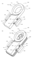
- FIG. 1 is a perspective view showing a simplified structure of a lighting device 100 for a smart device according to a first embodiment of the present invention.
- FIG. 1 is a front view simply illustrating a structure of a lighting device 100 for a smart device according to a first embodiment of the present invention.
- FIG. 2 is a rear view showing a simplified structure of the lighting device 100 for a smart device according to the present invention in accordance with the first embodiment.
- FIG. 2 is a right side view simply illustrating the structure of the lighting device 100 for a smart device according to the present invention in accordance with the first embodiment.
- FIG. 1 is a left side view simply illustrating the structure of a lighting device 100 for a smart device according to a first embodiment of the present invention.
- FIG. 1 is a front view simply illustrating a structure of a lighting device 100 for a smart device according to a first embodiment of the present invention.
- FIG. 2 is a rear view showing a simplified structure of the lighting device 100 for a smart device according to the
- FIG. 1 is a plan view simply illustrating a structure of a lighting device 100 for a smart device according to a first embodiment of the present invention.
- FIG. 2 is a bottom view showing a simplified structure of the lighting device 100 for a smart device according to the present invention in accordance with the first embodiment.
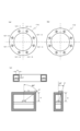
- 13 is a diagram showing a preferable arrangement of the LED element 121 within the space of the surrounding housing 110.
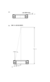
- FIG. 1 is a diagram showing a vertical cross section of the arrangement relationship between the height of the inner peripheral wall surface 111 of the circumferential housing 110, the inner diameter of the circumferential housing 110, and the camera lens 210.
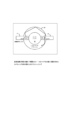
- FIG. 1 is a diagram simply showing a configuration in which the light emitted from an LED element 121 of a circular light source 120 is inclined at an angle D.
- FIG. 2 is a diagram simply illustrating a circuit configuration of the smart device lighting device 100.
- 11A and 11B are diagrams illustrating a first group lighting pattern and a second group lighting pattern.
- 13 is a diagram illustrating a lighting pattern when LED elements 121 are divided into three groups.
- FIG. 13 is a diagram showing a change in supply current to each group in a pattern in which LED elements 121 are divided into three groups.
- FIG. 1 is a diagram simply illustrating an example of the configuration of a flash ring shown in Patent Document 1 (JP 2021-182147 A) in the prior art.
- FIG. 1 is a diagram simply illustrating an example of the configuration of a ring flash shown in Patent Document 2 (JP Patent Publication No. 2019-512147) in the prior art.
- FIG. 1A is a perspective view of a smart device lighting device 100
- FIG. 1B is a perspective view showing a smart device 200 to which the smart device lighting device 100 is externally attached.
- Fig. 2 is a front view
- Fig. 3 is a rear view
- Fig. 4 is a right side view
- Fig. 5 is a left side view
- Fig. 6 is a plan view
- Fig. 7 is a bottom view.
- (a) shows only smart device lighting device 100
- (b) shows smart device lighting device 100 externally attached to smart device 200.
- the lighting device 100 for smart devices is configured with a rotating housing 110, a rotating light source 120, a right mounting device 130, a left mounting device 140, and a main body 150.
- the circular housing 110 is a circular housing having an inner peripheral wall surface 111, an outer peripheral wall surface 112, a light-transmitting diffusion plate 113 attached to the top surface, a bottom surface 114, and a central hole 115.
- the inner wall surface 111 is a wall surface that divides the inner circumference of the rotating housing 110, and the hole that the inner wall surface 111 goes around is the central hole 115. Note that although it is circular in this figure, it may be circular, elliptical, or polygonal, and although it basically goes around, it may also be horseshoe-shaped with a sealed gap in one part.
- the outer peripheral wall surface 112 is a wall surface that separates the outer peripheral side of the orbiting housing 110, and the diameter around which this outer peripheral wall surface 112 orbits is the maximum diameter of the light source of the orbiting light source 120. Although it is circular in this figure, it may be circular, elliptical, or polygonal, and although it is basically orbiting, it may also be horseshoe-shaped with a sealed gap in one part.
- the light-transmitting diffusion plate 113 is a member attached in a circular shape to the top surface of the circular housing 110 (i.e., the inner wall surface 111 and the outer wall surface 112), and is made of a material that is light-transmitting and light-diffusing. In other words, it is a material that transmits the irradiated light emitted from the LED element 121 mounted inside and has light-diffusing properties. For example, it may be made of a milky white polycarbonate material, but this is not limited to this.
- the bottom surface 114 is the bottom surface of the circular housing 110 (i.e., the bottom surface of the circular space partitioned by the inner peripheral wall surface 111 and the outer peripheral wall surface 112).
- the bottom surface 114 is a concentric doughnut shape in this drawing, it may be a circle, an ellipse, or a polygon to match the inner peripheral wall surface 111 and the outer peripheral wall surface 112, and although it is basically a circular shape, it may also be a horseshoe shape with a partially sealed slit.
- a substrate on which a plurality of LED elements 121 are arranged is attached on the bottom surface 114 as will be described later.
- the central hole 115 is a hole provided in the center of the orbiting light source 120. As shown in each of Figs. 1(b) to 7(b), the orbiting light source 120 is attached externally to the smart device 200, and LED irradiation light is emitted forward from the orbiting light source 120, and this hole 115 serves as a window, allowing the camera lens 210 of the smart device 200 to capture an image of the front. Since the LED irradiation light is emitted forward from the orbiting light source 120 so as to surround the camera lens 210 of the smart device 200, the reflected light reflected by a subject in front passes through the hole 115 and can be received by the camera lens 210.
- the size of the central hole 115 is not limited, but may be, for example, about 2 cm to 7 cm, as long as it is a hole diameter for the camera lens 210 of the smart device 200.
- the rotating light source 120 is a light source that emits irradiation light from a light-transmitting diffusion plate 123 attached to the upper surface of the rotating housing 120 .
- the orbiting light source 120 includes a plurality of LED elements 121 (not shown in FIGS. 1 to 7, but shown in FIG. 8 and subsequent figures) mounted in a circular pattern inside the orbiting housing 110 as a light source. In this configuration example, eight LED elements 121 are mounted in the internal space of the orbiting housing 110, as described later.
- the plurality of LED elements 121 may be light-emitting diodes without any particular limitation, but LED elements having the following specifications are preferred.
- the important factors required for the LED illumination light are (1) the light must be able to withstand shooting in low light environments, (2) the light must be able to withstand close-up shooting in which the subject is close to the camera, (3) the light must not cause glare even if the subject is a white object, (4) the light must be able to capture the subject with high color reproducibility, and (5) the light must be evenly and brightly illuminated.
- the ranges of color temperature CT and color rendering index Ra of the LED element that satisfy the above conditions are set to the following numerical ranges.
- the color temperature CT of the LED element falls within the range of the following (Equation 9). (Equation 9) 4000K ⁇ CT ⁇ 6500K
- the range of color rendering index Ra of the LED element is given by the following formula (10). (Number 10) 90 ⁇ Ra ⁇ 100
- FIG. 8 is a diagram showing a preferable arrangement of the LED elements 121 within the space of the surrounding housing 110.
- FIG. 8A and 8B are bird's-eye views in plan of the arrangement of a plurality of LED elements 121 in a surrounding casing 110.
- FIG. 8(a) the outer shape of the orbital housing 110 is a circle, and in FIG. 8(b), the outer shape of the orbital housing 110 is a polygon (regular dodecagon). In either case, there are eight LED elements 121 in the internal space of the orbital housing 110, which are arranged in a orbital shape.
- each LED element 121 there are four sets, each consisting of two LED elements 121, and the sets are arranged symmetrically on either side of the vertical axis or the horizontal axis.
- the intervals are about 40 degrees (for example, the angle formed by the LED element 121-1 and the LED element 121-2 from the center), and the intervals between each set (for example, the angle formed by the LED element 121-2 and the LED element 121-3 from the center) are 50 degrees.
- the lighting control and drive control of each LED element 121 will be described later.
- FIG. 8C is a vertical cross-sectional view showing the arrangement of one LED element 121 within the surrounding housing 110.
- the wall surfaces of the circumferential housing are shown in cross section, with vertical cross sections of the inner circumferential wall surface 111, the outer circumferential wall surface 112, the light-transmitting diffusion plate 113, and the bottom surface 114 being depicted.
- One LED element 121 is disposed near the center on a circuit board 122. Note that the arrangement example of Fig.
- the arrangement position of one LED element 121 in the circumferential direction (the arrangement position in the left-right direction in the figure) and the arrangement height of the circuit board 122 (the arrangement position in the up-down direction in the figure) may have other positional relationships.
- the height H from the LED element 121 to the light-transmitting diffusion plate 113 and the distance W from the center of the arrangement position of the LED element 121 to the LED element 121 and the inner circumferential wall surface 111 are arranged so as to satisfy the following (Equation 11).
- FIG. 9 is a diagram showing a vertical cross section of the arrangement relationship between the height of the inner peripheral wall surface 111 of the circumferential housing 110, the inner diameter of the circumferential housing 110, and the camera lens 210 of the smart device 200.
- 9 illustrates a vertical cross section of the circumferential housing 110 and the smart device 200. Since the circumferential housing 110 rotates, the space of the circumferential housing 110 on the left side and the circumferential housing 110 on the right side are illustrated. Between them is a central hole 115 of the circumferential housing 110.
- the smart device 200 is disposed below the circumferential housing 110, and the camera lens 210 is located in the center of the central hole 115 of the circumferential housing 110.
- FIG. 9 the smart device 200 is disposed below the circumferential housing 110, and the camera lens 210 is located in the center of the central hole 115 of the circumferential housing 110.
- the height CH of the inner wall surface of the circumferential housing 110 and the distance CW from the center of the camera lens 210 of the smart device to the inner wall surface 111 of the circumferential housing 110 satisfy the following condition (Equation 12). (Number 12) 1 mm ⁇ CH ⁇ 1.7 CW
- Figure 9 (b) illustrates the height CH of the inner wall surface of the swivel housing 110 and the distance CW from the center of the camera lens 210 of the smart device to the inner wall surface 111 of the swivel housing 110 in the upper limit case of (Equation 12).
- Smart devices often use wide-angle lenses for their camera lenses, and the angle of view is often around 60 degrees.
- the height CH of the inner wall surface of the orbiting housing 110 needs to be a certain height, so it is considered that a height of at least 1 mm is necessary. From these conditions, the numerical range of 1 mm ⁇ CH ⁇ 1.7 CW is derived.
- FIG. 10 is a diagram simply showing a configuration in which the light emitted from the LED element 121 of the orbiting light source 120 is inclined at an angle D. In FIG. As shown in FIG.
- FIG. 10A an inclination angle D is provided so that the irradiation direction of the LED element is inclined toward the center of the camera lens of the smart device.
- FIG. 10B is a diagram simply showing the irradiated light when the inclination angle D is the upper limit value of (Equation 13).
- the condition is that the irradiated light is emitted so as to converge to the center point 300 mm away. Under this condition, if the subject is located 300 mm away, it will be illuminated most brightly. Even if it is located before or after that, it will be illuminated with converged light.
- the lighting device for smart devices of the present invention has the advantage that it can also take pictures in close-up mode where the subject is close, so if the condition of the above (Equation 13) is met, the subject is brightly illuminated and the shooting conditions are improved, so it can be said to be a preferable range.
- the right-side wearing fixture 130 and the left-side wearing fixture 140 are used to wear the smart device lighting device 100 on the smart device 200.
- the smart device lighting device 100 is fixed and attached to the smart device 200 by clamping the smart device 200 from the left and right between the right wearing fixture 130 and the left wearing fixture 140.
- the right wearing fixture 130 includes a right gripping part 131 that grips the right edge of the smart device 200 by sandwiching it from above and below, and a right bridge part 132 that allows the left and right position of the right gripping part 131 to be changed.
- the left wearing device 140 has a left gripping portion 141 that grips the left edge of the smart device 200 by pinching it from above and below, and a left bridge portion 142 that allows the position of the left gripping portion 141 to be changed.
- the right-side mounting fixture 130 and the left-side mounting fixture 140 clamp the edges of the smart device 200 from the left and right with the right-side gripping portion 131 and the left-side gripping portion 141, respectively, and the clamping distance is adjusted by the right-side bridge portion 132 and the left-side bridge portion 142 sliding, respectively.
- the smart device 200 can be fixed in place while the edges are clamped from the left and right (fixing structure not shown).
- the end of the left bridge portion 142 is shown in the recess of the right edge of the main body 150 of the smart device lighting device 100.
- the depth of the end face of the left bridge portion 142 may vary depending on the width of the smart device 200, but in this case, the end face of the left bridge portion 142 is simply shown in the recess of the right edge.
- the sliding directions of the right bridge portion 132 and the left bridge portion 142 are offset from each other so as not to overlap and collide with each other.
- an extension bridge member (not shown here) may be used to extend the length of the right bridge portion 132 and the left bridge portion 142.
- the orbiting light source 120 is mounted to surround the camera lens 210 of the smart device.
- the lighting device 100 for smart devices is attached so that the hole 115 in the center of the orbiting housing 110 is positioned like a window, thereby maintaining an open state in front of the camera lens 210 of the smart device.
- the main body 150 of the smart device lighting device 100 serves as a base for the circumferential housing 110, and also serves as a base for slidably supporting the right-side mounting fixture 130 and the left-side mounting fixture 140.
- the main body 150 is rectangular, but the external shape is not particularly limited.
- a battery may be built into the main body 150 to supply power for driving the LED element 121 .
- the smart device 200 is a smartphone or a tablet type information terminal equipped with a camera function.
- the smart device 200 is not particularly limited, but smartphones and tablet-type information terminals that have become widespread in recent years generally incorporate a camera lens 210 and are often equipped with a camera photographing function.
- smartphones or tablet-type information terminals the length, width, and height of the housing fall within a certain range regardless of the manufacturer, so it is possible to attach the smart device lighting device 100 of the present invention externally.
- 11A is a diagram showing a simplified circuit configuration of the smart device lighting device 100. Only the components related to the electronic circuit are shown.
- the orbiting light source 120 is formed of eight LED elements, ie, LED elements 121-1 to 121-8, which are arranged in a circumferential manner.
- the four LED elements 121-1, 121-2, 121-5, and 121-6 arranged along the vertical axis are defined as the first group of LED elements 121
- the four LED elements 121-3, 121-4, 121-7, and 121-8 arranged along the horizontal axis are defined as the second group of LED elements 121.
- the first group of LED elements 121 is arranged along the vertical axis
- the second group of LED elements 121 is arranged along the horizontal axis.
- the lighting device 100 for a smart device includes a switching control unit 160 and a battery 170.
- the switching control unit 160 and the battery 170 may be built into the main body 150.
- the switching control unit 160 is an electronic circuit that performs switching control of the LED elements. By mounting the switching control unit 160 and performing lighting control and drive control of the LED elements 121, it is possible to perform various lighting control and drive control other than a simple lighting/extinguishing control by an ON/OFF switch.
- the lighting control of the LED elements 121 by the switching control section 160 includes a total lighting pattern and a lighting pattern for each group.
- 11B is a diagram for explaining all the lighting patterns, in which the lit LED elements 121 are shown in black. 11B, the full lighting pattern is a control for switching between lighting and extinguishing all of the LED elements 121. This can be said to be the same as a simple lighting/extinguishing control using an ON/OFF switch.
- FIG. 12 is a diagram illustrating the first group lighting patterns and the second group lighting patterns.
- the first group lighting pattern as shown in FIG. 12(a), is a pattern in which the first group of LED elements 121 (four LED elements: LED element 121-1, LED element 121-2, LED element 121-5, and LED element 121-6) are lit and the second group of LED elements 121 (four LED elements: LED element 121-3, LED element 121-4, LED element 121-7, and LED element 121-8) are turned off.
- the second group lighting pattern is a pattern in which the first group of LED elements 121 are turned off and the second group of LED elements 121 are turned on. In the drawing, the lit LED elements 121 are shown in black.
- each LED element 121 is arranged in a circumferential manner, the direction and angle of the light irradiated from each LED element 121 to the subject differs, but there are various situations such as the outer shape of the subject, the three-dimensional uneven shape of the subject, the surface condition of the subject, the color of the subject, the way in which the user holds the camera lens 210 of the smart device 200, and the relative angle and relative distance between the subject and the camera lens 210 of the smart device 200.
- FIG. 13 is a diagram illustrating a lighting pattern when the LED elements 121 are divided into three groups.
- the LED elements are divided into a first group arranged along the vertical axis, a second group arranged along the horizontal axis, and a third group in which LED elements are arranged in the gaps between the first and second groups.
- the LED elements 121 belonging to the third group are four, LED elements 121-9, 121-10, 121-11, and 121-12, and are arranged in a cross shape.
- 13B is a diagram showing the third group lighting pattern.
- the LED elements 121 belonging to the third group are lit.
- the lit LED elements 121 are displayed in black.
- the first group lighting pattern and the second group lighting pattern may be similar to the lighting patterns in Figures 12(a) and 12(b), and illustration of the lighting patterns in the case where the LED elements 121 are divided into three groups is omitted.
- the technical significance of dividing the lighting patterns into three groups as shown in FIG. 13 is as follows.
- the first group lighting pattern in which the LED elements 121 are arranged along the vertical axis is preferred, and cases where the second group lighting pattern in which the LED elements 121 are arranged along the horizontal axis is preferred, in cases where lighting with good vertical and horizontal balance is preferred but the amount of light is too high with full lighting or when the remaining battery charge is low and power needs to be saved
- the third group lighting pattern can be used to achieve a relatively good vertical and horizontal balance and also to save power. In this way, there is the advantage that the lighting pattern can be selected in more detail according to various situations.
- the drive control of the LED element 121 by the switching control unit 160 includes static drive control (DC drive) and pulse drive control.
- Static drive control (DC drive) is a lighting method in which current is constantly applied to the LED element 121.
- the advantage of static drive control (DC drive) is that a constant current is always passed through the LED element 121, so that fluctuations in illumination such as flicker do not occur.
- the disadvantage of static drive control (DC drive) is that the power consumption is large and the life of the LED element 121 may be shortened.
- Pulse drive control is also called dynamic drive control, and is a drive control for turning on and off the LED element 121 at a constant frequency at high speed.
- the advantage of pulse drive control is that it reduces power consumption and extends the life of the LED element 121.
- the disadvantage of pulse drive control is that when driven at a low frequency, for example, a frequency of 50 Hz (Hertz) or less, flickering is easily noticeable to the human eye, and when photographing with a camera, the amount of light hitting the subject at the moment of photographing changes due to flickering, which can cause the photographed image to be unstable. In particular, when photographing a video at 30 frames per second, the fact that the photographed image is unstable due to this flickering is a major disadvantage.
- the lighting device 100 for smart devices of the present invention is designed to be portable, and when the power source is a battery 170 mounted inside the main body 150, the advantage of low power consumption due to pulse drive control is important. Therefore, the smart device 200 is equipped with a mechanism for suppressing the disadvantage of unstable captured images due to flicker when taking pictures with the camera.
- the first innovation for stabilizing captured images is to perform pulse control so as to synchronize the timing of the pulse-driven lighting of the LED element 121 with the timing of capturing video frames by the camera capture function of the smart device 200.
- the second technique for stabilizing captured images is to perform pulse drive control by shifting the phase of the supply current if the LED elements 121 are grouped into multiple groups so that at least one of the LED elements 121 is lit at any given time.
- the phase of the pulsed drive supply current for the first group of LED elements 121, the phase of the pulsed drive supply current for the second group of LED elements 121, and the phase of the pulsed drive supply current for the third group of LED elements are shifted equally (for example, by 120°), it is possible to perform pulse drive control so that at least one of the LED elements 121 is lit regardless of the timing.
- FIG. 14 is a diagram showing changes in supply current to each group in a pattern in which the LED elements 121 are divided into three groups.
- commercial power sources are three-phase AC, with each phase being a sine wave shifted by 120 degrees. Therefore, if the LED elements 121 are divided into three groups, it is convenient to supply current to each group by giving the current of each phase of the three-phase AC power source.
- the supply current of each phase to each group is a sine wave, but the phases are shifted by 120 degrees, so that the supply current to any of the LED elements 121 is adequately secured at any timing, and although there is pulsation in the amount of light when viewed in detail, the orbiting light source 120 can be controlled to be almost always on. At the same time, power consumption can be reduced.
- the drop in the sine wave can be made gentler.
- the lighting device for smart devices of the present invention can be widely used as a lighting device when taking pictures with a camera using a smart device such as a smartphone or tablet information terminal.
Landscapes
- Physics & Mathematics (AREA)
- General Physics & Mathematics (AREA)
- Stroboscope Apparatuses (AREA)
Priority Applications (2)
| Application Number | Priority Date | Filing Date | Title |
|---|---|---|---|
| JP2025544325A JPWO2025069340A1 (https=) | 2023-09-28 | 2023-09-28 | |
| PCT/JP2023/035502 WO2025069340A1 (ja) | 2023-09-28 | 2023-09-28 | スマートデバイス用照明装置 |
Applications Claiming Priority (1)
| Application Number | Priority Date | Filing Date | Title |
|---|---|---|---|
| PCT/JP2023/035502 WO2025069340A1 (ja) | 2023-09-28 | 2023-09-28 | スマートデバイス用照明装置 |
Publications (1)
| Publication Number | Publication Date |
|---|---|
| WO2025069340A1 true WO2025069340A1 (ja) | 2025-04-03 |
Family
ID=95203113
Family Applications (1)
| Application Number | Title | Priority Date | Filing Date |
|---|---|---|---|
| PCT/JP2023/035502 Pending WO2025069340A1 (ja) | 2023-09-28 | 2023-09-28 | スマートデバイス用照明装置 |
Country Status (2)
| Country | Link |
|---|---|
| JP (1) | JPWO2025069340A1 (https=) |
| WO (1) | WO2025069340A1 (https=) |
Citations (9)
| Publication number | Priority date | Publication date | Assignee | Title |
|---|---|---|---|---|
| JP2003101836A (ja) * | 2001-09-21 | 2003-04-04 | Kyocera Corp | 小型ストロボ装置 |
| JP2003114462A (ja) * | 2001-10-03 | 2003-04-18 | Casio Comput Co Ltd | 撮像装置用閃光装置、閃光装置付撮像装置及び撮像方法 |
| JP2004354702A (ja) * | 2003-05-29 | 2004-12-16 | Casio Comput Co Ltd | 発光部付き撮像装置、発光方法、及びプログラム |
| JP2010160286A (ja) * | 2009-01-07 | 2010-07-22 | Softbank Mobile Corp | 携帯電話用拡張機器 |
| JP2014029486A (ja) * | 2012-07-02 | 2014-02-13 | Kenji Yoshida | レンズユニット |
| JP2019141321A (ja) * | 2018-02-21 | 2019-08-29 | ヤーマン株式会社 | 撮像システム、撮像方法、カメラアダプタ及びプログラム |
| JP2020509403A (ja) * | 2017-02-08 | 2020-03-26 | エッセンリックス コーポレーション | アッセイ用の光学系、デバイス、およびシステム |
| JP2021182147A (ja) * | 2016-04-26 | 2021-11-25 | ルミレッズ リミテッド ライアビリティ カンパニー | カメラレンズを取り囲むledフラッシュリング |
| JP2022062221A (ja) * | 2016-04-22 | 2022-04-19 | フィットスキン インコーポレイテッド | 電子装置を用いた皮膚分析のためのシステムおよび方法 |
Family Cites Families (9)
| Publication number | Priority date | Publication date | Assignee | Title |
|---|---|---|---|---|
| US7702139B2 (en) * | 2006-10-13 | 2010-04-20 | Carestream Health, Inc. | Apparatus for caries detection |
| KR100993141B1 (ko) * | 2010-02-25 | 2010-11-09 | 조민구 | 엘이디 조명장치 |
| KR101757441B1 (ko) * | 2015-12-29 | 2017-07-11 | 이준택 | Led를 이용한 의료용 자연광원 발생기 |
| JP6519878B2 (ja) * | 2016-01-06 | 2019-05-29 | 株式会社井澤 | 照明機能を備えた近接撮影装置 |
| KR20170138139A (ko) * | 2016-06-07 | 2017-12-15 | (주)유브이앤텍 | 의료진단에 사용하는 led 기구 |
| KR102057580B1 (ko) * | 2018-02-02 | 2019-12-19 | 이준택 | 의료용 쉐이드 라이트 |
| US10738981B2 (en) * | 2018-11-21 | 2020-08-11 | HASS Corp. | LED lighting device for mobile phone |
| US20220137491A1 (en) * | 2020-10-30 | 2022-05-05 | Moment Inc | Mobile smart device case with accessory interface |
| JP7182832B1 (ja) * | 2021-03-10 | 2022-12-05 | 株式会社坪田ラボ | 円錐角膜及び乱視等の簡易診断補助装置及び診断補助システム |
-
2023
- 2023-09-28 JP JP2025544325A patent/JPWO2025069340A1/ja active Pending
- 2023-09-28 WO PCT/JP2023/035502 patent/WO2025069340A1/ja active Pending
Patent Citations (9)
| Publication number | Priority date | Publication date | Assignee | Title |
|---|---|---|---|---|
| JP2003101836A (ja) * | 2001-09-21 | 2003-04-04 | Kyocera Corp | 小型ストロボ装置 |
| JP2003114462A (ja) * | 2001-10-03 | 2003-04-18 | Casio Comput Co Ltd | 撮像装置用閃光装置、閃光装置付撮像装置及び撮像方法 |
| JP2004354702A (ja) * | 2003-05-29 | 2004-12-16 | Casio Comput Co Ltd | 発光部付き撮像装置、発光方法、及びプログラム |
| JP2010160286A (ja) * | 2009-01-07 | 2010-07-22 | Softbank Mobile Corp | 携帯電話用拡張機器 |
| JP2014029486A (ja) * | 2012-07-02 | 2014-02-13 | Kenji Yoshida | レンズユニット |
| JP2022062221A (ja) * | 2016-04-22 | 2022-04-19 | フィットスキン インコーポレイテッド | 電子装置を用いた皮膚分析のためのシステムおよび方法 |
| JP2021182147A (ja) * | 2016-04-26 | 2021-11-25 | ルミレッズ リミテッド ライアビリティ カンパニー | カメラレンズを取り囲むledフラッシュリング |
| JP2020509403A (ja) * | 2017-02-08 | 2020-03-26 | エッセンリックス コーポレーション | アッセイ用の光学系、デバイス、およびシステム |
| JP2019141321A (ja) * | 2018-02-21 | 2019-08-29 | ヤーマン株式会社 | 撮像システム、撮像方法、カメラアダプタ及びプログラム |
Also Published As
| Publication number | Publication date |
|---|---|
| JPWO2025069340A1 (https=) | 2025-04-03 |
Similar Documents
| Publication | Publication Date | Title |
|---|---|---|
| US9097413B2 (en) | LED nightlight system having an image projection feature | |
| US11096255B2 (en) | Ambient light sensing lighting system | |
| US20150276178A1 (en) | Led nightlight system having an image projection feature | |
| CN111314586B (zh) | 补光组件及其控制方法、摄像模组及移动终端 | |
| US20160209025A1 (en) | Lighting device attachment for mobile devices | |
| EP2249203B1 (en) | Ring light apparatus with variable projection angle | |
| CN110784657A (zh) | 摄像设备和监视系统 | |
| US9618827B2 (en) | Illumination device for performing videography and photography with mobile devices | |
| JP3170395U (ja) | リング状光源装置を有するカメラ | |
| CN101213831B (zh) | 具有扫描型闪光灯的数字图像捕获设备 | |
| US5408389A (en) | Interrupted light source | |
| CN103986866A (zh) | 成像装置、成像方法及发光装置 | |
| JP2014081474A (ja) | 撮影用照明装置および撮像装置 | |
| JP2008158247A (ja) | 撮像装置用フラッシュ装置および撮像装置 | |
| US11096260B2 (en) | Ambient light sensing lighting strobe system | |
| US11864293B2 (en) | Hard and soft light module with ambient light sensing | |
| WO2025069340A1 (ja) | スマートデバイス用照明装置 | |
| JP2009071404A (ja) | 被写体照明制御装置及びそのプログラム | |
| US20090219707A1 (en) | Adjustable lens with self-illuminated scale | |
| CN1487327A (zh) | 图象显示装置 | |
| TW201329607A (zh) | 影像擷取器用短距光源裝置及具該裝置的影像擷取器 | |
| KR20150003053U (ko) | 카메라용 엘이디 조명장치 | |
| KR20060088296A (ko) | 회전형 플래시가 구비되는 이동통신 단말기 | |
| KR102128657B1 (ko) | 마이크로 미러 기반의 화상 조명장치 | |
| CN214840263U (zh) | 一种灯具 |
Legal Events
| Date | Code | Title | Description |
|---|---|---|---|
| 121 | Ep: the epo has been informed by wipo that ep was designated in this application |
Ref document number: 23953281 Country of ref document: EP Kind code of ref document: A1 |
|
| ENP | Entry into the national phase |
Ref document number: 2025544325 Country of ref document: JP Kind code of ref document: A |
|
| WWE | Wipo information: entry into national phase |
Ref document number: 2025544325 Country of ref document: JP |