WO2025069321A1 - 移動体の制御装置及び制御方法 - Google Patents
移動体の制御装置及び制御方法 Download PDFInfo
- Publication number
- WO2025069321A1 WO2025069321A1 PCT/JP2023/035452 JP2023035452W WO2025069321A1 WO 2025069321 A1 WO2025069321 A1 WO 2025069321A1 JP 2023035452 W JP2023035452 W JP 2023035452W WO 2025069321 A1 WO2025069321 A1 WO 2025069321A1
- Authority
- WO
- WIPO (PCT)
- Prior art keywords
- thrust
- control
- command
- movement
- moving body
- Prior art date
- Legal status (The legal status is an assumption and is not a legal conclusion. Google has not performed a legal analysis and makes no representation as to the accuracy of the status listed.)
- Pending
Links
Images




Classifications
-
- B—PERFORMING OPERATIONS; TRANSPORTING
- B23—MACHINE TOOLS; METAL-WORKING NOT OTHERWISE PROVIDED FOR
- B23B—TURNING; BORING
- B23B23/00—Tailstocks; Centres
-
- G—PHYSICS
- G05—CONTROLLING; REGULATING
- G05B—CONTROL OR REGULATING SYSTEMS IN GENERAL; FUNCTIONAL ELEMENTS OF SUCH SYSTEMS; MONITORING OR TESTING ARRANGEMENTS FOR SUCH SYSTEMS OR ELEMENTS
- G05B19/00—Program-control systems
- G05B19/02—Program-control systems electric
- G05B19/18—Numerical control [NC], i.e. automatically operating machines, in particular machine tools, e.g. in a manufacturing environment, so as to execute positioning, movement or co-ordinated operations by means of program data in numerical form
Definitions
- This disclosure relates to a control device and method for a moving body that uses thrust control to control the pressing of a moving body in an industrial machine against a pressing object.
- Patent Document 1 describes a control device that performs pressing control to press a moving body such as a tailstock inside an industrial machine against a pressing object.
- Patent Document 1 describes a machine tool control device for a combined lathe in which both sides of a long workpiece are grasped by two opposing headstocks and the workpiece is machined while the two headstocks are driven in sync.
- the control device for the machine tool described in Patent Document 1 is composed of two pressing completion determination means for pressing the two headstocks against the workpiece, two command values for moving the two headstocks, two parameters for setting data required for the CNC to perform calculations such as axis movement data, and two torque limiting amounts for determining the torque amounts of the two Z-axis servo motors.
- Patent Document 2 describes a method for creating approach and retract paths in NC machining, which automatically creates optimal approach (retract) paths taking into consideration the machining portion of the workpiece, the shape of the nearby workpiece, the amount of cutting allowance, etc., when creating NC data for contour machining of a workpiece with a tool having a cutting edge on the side.
- the method for creating approach and retract paths in NC machining described in Patent Document 2 sets priorities in advance for approach (retract) path patterns, obtains an evaluation score for a predetermined evaluation element for an approach (retract) path point sequence with a constant Z value created for each pattern, determines which of the predetermined judgment zones the evaluation point belongs to, and creates an approach (retract) path that changes the Z value and calculates the evaluation score when the evaluation point belongs to an unusable zone of the judgment zone.
- the approach (retract) path to be adopted is determined according to the priority, and if there is only an approach (retract) path with an evaluation point that belongs to a warning zone of the judgment zone, the path to be adopted is determined according to the distance between the workpiece and the tool.
- Patent Document 3 describes an inexpensive collision avoidance system for a machine tool that can avoid collisions caused by an operator's operational error or a mistake in approaching when starting machining.
- the collision avoidance system for a machine tool described in Patent Document 3 is a collision avoidance system that avoids collision between a moving body and a workpiece in a machine tool having, for example, a table on which a workpiece is placed, a moving body (ram, saddle), and moving axes (X-axis, Y-axis, Z-axis, W-axis) that move the moving body or the table linearly, and is described as having a non-contact distance sensor (ultrasonic sensor) attached to the moving body and detecting the distance to the workpiece, and a collision avoidance control means (NC device), and the collision avoidance control means is described as having a collision determination unit that determines whether the sensor signal of the distance sensor is shorter than a distance set value, and a collision avoidance processing unit that performs processing to avoid collision between the moving body and the workpiece when the collision
- a known technique for performing the press-fit control is to control the thrust force of a drive shaft, which is a control for moving an axis while the torque generated by a drive unit such as a motor is constant.
- a drive unit such as a motor
- a first representative aspect of the present disclosure is a control device for a moving body that executes control of pressing a moving body in an industrial machine against a pressing target by thrust control, a thrust command generating unit that generates a thrust command for the moving body based on at least one of a program command and input information from an input unit, the thrust command generating unit being related to the thrust control of the moving body; a movement command generating unit that generates a movement command for the moving body based on at least one of a program command and input information from an input unit, the program command and the input information relating to the movement of the moving body; a determination unit that determines whether or not to permit movement of the moving body and whether or not to release the thrust control and switch to position control based on the pushing direction of the thrust command and the movement direction of the movement command;
- the control device is provided with:
- a second representative aspect of the present disclosure is a computer as a control device for a moving body that executes control of pressing a moving body in an industrial machine against a pressing target by thrust control, the computer comprising: A process of generating a thrust command for the moving body based on at least one of a program command and input information from an input unit, which is related to the thrust control of the moving body; A process of generating a movement command for the moving object based on at least one of a program command and input information from an input unit, which is related to the movement of the moving object; a process of determining whether or not to permit the movement of the moving body and whether or not to release the thrust control and switch to position control based on the pushing direction of the thrust command and the movement direction of the movement command;
- the present invention relates to a method for controlling a moving object, the method comprising:
- FIG. 11 is an explanatory diagram for explaining pressing control for pressing the tailstock against the workpiece.
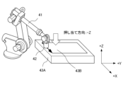
- FIG. FIG. 1 is an explanatory diagram for explaining control for performing friction stir welding by pressing a rotating tool against a workpiece.
- FIG. 2 is a block diagram showing a configuration example of a control device according to an embodiment of the present disclosure. 4 is a flowchart showing an example of the operation of the control device.
- FIG. 1 is an explanatory diagram illustrating a first configuration example of a control system including a control device and an industrial machine.
- 11 is an explanatory diagram showing the operation of the control system of the first configuration example when a user uses a jog feed switch to instruct jog feed of the W axis.
- FIG. 2 is an explanatory diagram showing a second configuration example of a control system including a control device and an industrial machine.
- 11 is a diagram for explaining an example in which a determination unit uses a coordinate system including an axis parallel to an axis along which pressing control is performed.
- the pressing control is a control for pressing a moving body in an industrial machine against a pressing target, such as a machine tool or a robot.
- An example of the pressing control is the control of pressing the tailstock against the workpiece to prevent the workpiece from shaking during turning.
- the tailstock corresponds to the moving body and the workpiece corresponds to the object to be pressed.
- the tailstock may be the object to be pressed against and the workpiece corresponds to the moving body, and the workpiece may be pressed against the fixed tailstock.
- FIG. 1 is an explanatory diagram for explaining the pressing control for pressing the tailstock against the workpiece. 1, and is pressed against an end face of the long workpiece 32 fixed by a chuck 33.
- the workpiece 32 is machined by a tool 34.
- the tailstock 31 is connected to a ball screw or linear motor that is connected to a motor that rotates the rotating shaft, and the movement of the tailstock 31 is controlled by an axis control unit 104, described later, which is connected to the motor or linear motor that rotates the rotating shaft.
- pressing control is friction stir welding, in which a rotating tool attached to the hand of an industrial robot is pressed against a workpiece.
- the rotating tool corresponds to the moving body and the workpiece corresponds to the object to be pressed.
- the rotating tool may be the object to be pressed and the workpiece corresponds to the moving body, and the workpiece may be pressed against a rotating tool whose position is fixed.
- FIG. 2 is an explanatory diagram for explaining control for performing friction stir welding by pressing a rotating tool against a workpiece.
- the rotating tool 42 attached to the tip of the robot body 41 is controlled to approach the location where the workpieces 43A and 43B are to be joined in the negative (-) direction of the Z axis shown in Fig. 2, and is pressed against the location where the workpieces 43A and 43B are to be joined in the negative direction of the Z axis.
- the rotating tool 42 By moving the rotating tool 42 in the positive (+) direction of the X axis while being pressed against the negative direction of the Z axis, the workpieces 43A and 43B, which have been softened (turned to clay-like) by frictional heat, are mixed together, and the workpieces 43A and 43B are joined to each other.
- the robot body 41 uses motors to move multiple arms and the joints between the arms, moving the arms up, down, left and right to move the rotary tool 42.
- the movement of the arms is controlled by an axis control unit 104 (described later) that is connected to a motor that rotates the rotary shaft.
- FIG. 3 is a block diagram illustrating an example configuration of a control device according to an embodiment of the present disclosure.
- the control device 10 executes control of pressing a moving body in an industrial machine against a pressing object by thrust control.
- thrust control is control for moving an axis in a state where the torque generated in a driving unit such as a motor is constant.
- the moving body and the pressing object related to the pressing control executed by the control device 10 correspond to a tailstock 31 and a workpiece 32, respectively, in the example shown in Fig. 1, and correspond to a rotating tool 42 and workpieces 43A and 43B, respectively, in the example shown in Fig. 2, but are not limited to the examples shown in Figs. 1 and 2.
- the control device 10 includes a thrust command generating unit 101, a movement command generating unit 102, a judgment unit 103, and an axis control unit 104.
- the axis control unit 104 does not have to be provided within the control device 10, but may be provided outside the control device 10. In that case, the control device 10 is composed of the thrust command generating unit 101, the movement command generating unit 102, and the judgment unit 103.
- the thrust command generation unit 101 generates a thrust command for the moving body based on at least one of program commands and input information from an input unit such as a thrust command switch related to thrust control of the moving body, and outputs the generated thrust command to the judgment unit 103 and the axis control unit 104.
- the movement command generation unit 102 generates a movement command for the moving body based on at least one of program commands and input information from an input unit such as a jog feed switch or an alarm, which are related to the movement of the moving body, and outputs the generated movement command to the judgment unit 103 and the axis control unit 104.
- Jog feed refers to manually moving the moving body.
- the determination unit 103 determines whether or not to permit the movement of the moving body and whether or not to release thrust control and switch to position control based on the pushing direction of the thrust command output from the thrust command generation unit 101 and the movement direction of the movement command output from the movement command generation unit 102, and outputs the determination result to the axis control unit 104.
- Position control refers to control that moves the moving body to a set position.
- the determination unit 103 determines that the movement of the moving body is permitted when the thrust command pushing direction and the movement command moving direction are substantially opposite directions.
- substantially opposite directions refers to cases where the thrust command pushing direction and the movement command moving direction are opposite directions and parallel to each other, as well as cases where they are tilted to such an extent that they can be considered to be substantially opposite directions.
- the determination unit 103 determines that thrust control can be released and switched to position control. If the determination unit 103 determines that thrust control can be switched to position control, the axis control unit 104 switches to position control.
- the determination unit 103 determines that the movement of the moving body is not permitted (not permitted).
- Substantially the same direction means that the pressing direction of the thrust command and the moving direction of the movement command are the same direction and parallel to each other, as well as including cases where they are tilted to an extent that they can be considered to be substantially the same direction.
- the determination unit 103 determines that it is not possible to release the thrust control and switch to position control (switching is not possible).
- the axis control unit 104 controls the axis of the moving body, including controlling the movement of the moving body and controlling the switch from thrust control to position control, based on the judgment result of the judgment unit 103.
- the axis control unit 104 is, for example, a servo control device that controls a motor or a linear motor that rotates a rotating shaft, based on a movement command and a thrust command.
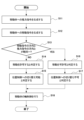
- FIG. 4 is a flowchart showing an example of the operation of the control device 10.
- step S11 the thrust command generation unit 101 generates a thrust command for the moving body based on at least one of the program commands and the input information from the input unit, which are related to thrust control of the moving body.
- step S12 the movement command generating unit 102 generates a movement command for the moving body based on at least one of the program command and the input information from the input unit, which are related to the movement of the moving body.
- Step S12 may be executed before step S11, or may be executed simultaneously with step S11.
- step S13 the determination unit 103 determines whether the pushing direction of the thrust command output from the thrust command generation unit 101 and the movement direction of the movement command output from the movement command generation unit 102 are substantially the same. If they are not substantially the same, the determination unit 103 proceeds to step S14, and if they are substantially the same, the determination unit 103 proceeds to step S16.
- step S14 the determination unit 103 determines that the movement of the moving object is permitted, and the process proceeds to step S15.
- step S15 the determination unit 103 determines that thrust control can be released and switched to position control, and the process proceeds to step S18.
- the order of steps S14 and S15 may be reversed, or steps S14 and S15 may be performed simultaneously.
- step S16 the determination unit 103 determines that the movement of the moving object is not permitted, and the process proceeds to step S17.
- step S17 the determination unit 103 determines that the thrust control cannot be released and switched to the position control, and the process proceeds to step S18.
- the order of steps S16 and S17 may be reversed, and steps S16 and S17 may be performed simultaneously.
- step S18 the axis control unit 104 controls the axis of the moving body, including controlling the movement of the moving body and controlling the switch from thrust control to position control, based on the determination result of the determination unit 103. Note that if the control device 10 does not include an axis control unit 104, step S18 is omitted.
- the thrust command generation unit 101 generates thrust commands for the moving body based on program commands
- the movement command generation unit 102 generates movement commands for the moving body based on program commands and input information from an input unit such as a jog feed switch.
- FIG. 5 is an explanatory diagram showing a first configuration example of a control system including a control device and an industrial machine.
- the control system 1A shown in FIG. 5 includes a control device 10, an industrial machine 30, and two jog feed switches 21 and 22.
- the industrial machine 30 includes a tailstock 31, a chuck 33 to which a long workpiece 32 is attached, and a tool 34, as shown in FIG. 1.
- the control device 10 includes a thrust command generator 101, a movement command generator 102, a determination unit 103, and an axis control unit 104, as shown in FIG. 3.
- a jog feed switch 21 for instructing the tailstock 31 to move in the positive (+) direction of the W axis, and a jog feed switch 22 for instructing the tailstock 31 to move in the negative (-) direction of the W axis are connected to the movement command generator 102.
- the movement command generation unit 102 generates a movement command based on a program to move the tailstock 31 from position "W0" to position "W-20” under position control, and outputs the movement command to the axis control unit 104.
- Position “W-20” is the position where the tailstock 31 is pressed against the workpiece 32.
- the workpiece 32 is at position "X0", "Z0".
- the thrust command generating unit 101 outputs a thrust command to the axis control unit 104 for performing pressing control using control (thrust control) that keeps the torque generated in the W axis constant based on a program.
- thrust command generator 101 generates a thrust control (pushing) command for axis control unit 104 and outputs it to axis control unit 104.
- the user may wish to interrupt program execution midway during thrust control (pushing) between TRQON and TRQOFF in a program and jog the W-axis during thrust control.
- FIG. 6 is an explanatory diagram showing the operation of the control system when the user uses the jog feed switch to instruct jog feed of the W axis.
- the direction of thrust control (pushing) is the negative direction of the W axis
- a push-down signal P1 is input as input information to movement command generating unit 102.
- a push-down signal P2 is input as input information to movement command generating unit 102.
- the movement command generating unit 102 When the movement command generating unit 102 receives the push-down signal P1, it generates a movement command in the positive direction for the W axis and outputs it to the judgment unit 103. On the other hand, when the movement command generating unit 102 receives the push-down signal P2, it generates a movement command in the negative direction for the W axis and outputs it to the judgment unit 103.
- the determination unit 103 receives a thrust command from the thrust command generation unit 101 to perform thrust control in the negative direction of the W axis.
- the judgment unit 103 allows the movement because the pushing direction of the thrust command and the moving direction of the movement command are substantially opposite to each other. On the other hand, if the movement command is in a negative direction, the judgment unit 103 does not allow the movement because the pushing direction of the thrust command and the moving direction of the movement command are substantially the same to each other.
- the determination unit 103 determines that thrust control can be released and switched to position control.
- the determination unit 103 determines that thrust control cannot be released and switched to position control (switching is not possible).
- FIG. 7 is an explanatory diagram showing a second configuration example of a control system including a control device and an industrial machine.
- the control system 1B shown in FIG. 7 includes a control device 10, an industrial machine 40, and a switch panel 50.
- the industrial machine 40 includes a robot body 41, a rotary tool 42, and workpieces 43A and 43B, as shown in FIG.
- the control device 10 includes a thrust command generating unit 101, a movement command generating unit 102, a determining unit 103, and an axis control unit 104, as shown in FIG.
- the following description focuses on the differences in the operation of the thrust command generator 101, the movement command generator 102, and the determination unit 103 in the pressing control in this configuration example from the first configuration example.
- the direction of thrust control (pushing) of the rotating tool 42 is the negative direction of the Z axis, and the directions perpendicular to the Z axis direction are the X axis direction and the Y axis direction, respectively.
- the user may wish to perform jog feed while performing friction stir welding by pressing the rotating tool 42 against the workpieces 43A and 43B in the negative direction of the Z axis.
- Jog feed can be specified in six directions: the positive (+) and negative (-) directions of the X axis, the positive (+) and negative (-) directions of the Y axis, and the positive (+) and negative (-) directions of the Z axis.
- the switch panel 50 is equipped with jog feed switches 51, 52 for jog feed in the positive (+) and negative (-) directions of the X-axis, jog feed switches 53, 54 for jog feed in the positive (+) and negative (-) directions of the Y-axis, and jog feed switches 55, 56 for jog feed in the positive (+) and negative (-) directions of the Z-axis.
- the thrust command generation unit 101 outputs a thrust command to the axis control unit 104 to perform pressing control using control (thrust control) that keeps the torque generated on the Z axis constant based on a program.
- the switch panel 50 When the user presses any one of the jog feed switches 51 to 56 shown in FIG. 7, the switch panel 50 inputs a press signal corresponding to the pressed jog feed switch to the movement command generating unit 102 as input information.
- the movement command generating unit 102 receives a push-down signal, it generates a movement command for the movement direction (positive or negative direction) of the axis (X-axis, Y-axis or Z-axis) corresponding to the push-down signal and outputs it to the judgment unit 103.
- the determination unit 103 receives a thrust command from the thrust command generation unit 101 to perform thrust control in the negative direction of the Z axis.
- the determination unit 103 permits movement if the movement command is either the positive direction of the X-axis or the positive direction of the Z-axis.
- the reason for permitting movement in the positive direction of the Z-axis is that the thrust direction of the thrust command and the movement direction of the movement command are substantially opposite to each other.
- the reason for permitting movement in the positive direction of the X-axis, which is different from the positive direction of the Z-axis, is that the tool is being sent in the positive direction of the X-axis for friction stir welding.
- the positive direction of the X-axis is an allowed direction.
- the determination unit 103 does not permit movement if the movement command is in a direction other than the positive direction of the X-axis and the positive direction of the Z-axis. Note that when friction stir welding moves from the positive direction of the X-axis to the positive direction of the Y-axis, the positive direction of the Y-axis becomes the allowed direction and the positive direction of the X-axis becomes the unallowed direction, and the allowed direction changes.
- the determination unit 103 determines that thrust control can be released and switched to position control. On the other hand, if the movement command is in a direction other than the positive direction of the Z axis, the determination unit 103 determines that thrust control cannot be released and switched to position control (switching is not possible).
- the reason why the determination unit 103 determines that thrust control cannot be released and switched to position control when the movement command is in an allowed direction, for example, the positive direction of the X axis, is that if thrust control is released while moving in the positive direction of the X axis to perform friction stir welding, it becomes difficult to perform friction stir welding correctly.
- the coordinate system for performing the pressing control described with reference to Figures 1, 2, and 5 to 7 may be freely selected.
- the coordinate system used by the determination unit 103 is a coordinate system including an axis parallel to the axis for performing the pressing control. Taking friction stir welding as an example, an example in which a coordinate system including an axis parallel to the axis on which the determination unit 103 performs the pressing control will be described with reference to FIG.
- FIG. 8 is a diagram for explaining an example in which the determination unit 103 uses a coordinate system including an axis parallel to the axis along which the pressing control is performed.
- the surface on which the workpiece 60A is placed is defined as the XM and YM axes, and the axis perpendicular to the XM and YM axes is defined as the ZM axis.
- the determination unit 103 can determine the direction of the pressing control and the direction of movement in a coordinate system consisting of the XM , YM , and ZM axes.
- the determination unit 103 it is easier for the determination unit 103 to make a determination using a coordinate system consisting of the ZW axis parallel to the pressing control direction, and the XW and YW axes perpendicular to the ZW axis.
- a coordinate system consisting of the ZW axis parallel to the pressing control direction, and the XW and YW axes perpendicular to the ZW axis.
- the following effects can be obtained. (1) It is possible to automatically determine whether the moving body can move and whether it is possible to return from thrust control to position control. (2) Even if the direction of a movement command is incorrect, the moving body will not move, so industrial machinery can be protected. (3) When moving a moving body under thrust control, the effort of returning to position control can be eliminated. For example, a program command for returning to position control is not required.
- the control device can be realized by hardware, software, or a combination of these.
- being realized by software means being realized by a computer reading and executing a program.
- the control device includes a processor such as a CPU (Central Processing Unit).
- the processor functions as an execution unit.
- the control device also includes an auxiliary storage device such as a HDD (Hard Disk Drive) that stores various control programs such as application software or an OS (Operating System), and a main storage device such as a RAM (Random Access Memory) for storing data temporarily required for the processor to execute a program.
- a processor such as a CPU (Central Processing Unit).
- the processor functions as an execution unit.
- the control device also includes an auxiliary storage device such as a HDD (Hard Disk Drive) that stores various control programs such as application software or an OS (Operating System), and a main storage device such as a RAM (Random Access Memory) for storing data temporarily required for the processor to execute a program.
- a HDD Hard Disk
- control device performs calculations based on the application software or OS, while the arithmetic processing unit reads the application software or OS from the auxiliary storage device and deploys the read application software or OS in the main storage device. Also, based on the results of this calculation, the control device controls various hardware components provided in the control device. In this way, the functional blocks of this embodiment are realized.
- the components included in the control device can be realized by hardware including electronic circuits, etc.
- ICs integrated circuits
- ASICs Application Specific Integrated Circuits
- FPGAs Field Programmable Gate Arrays
- CPLDs Complex Programmable Logic Devices
- Non-transitory computer readable media include various types of tangible storage media.
- Examples of non-transitory computer readable media include magnetic recording media (e.g., hard disk drives), magneto-optical recording media (e.g., magneto-optical disks), CD-ROM (Read Only Memory), CD-R, CD-R/W, and semiconductor memory (e.g., mask ROM, PROM (Programmable ROM), EPROM (Erasable PROM), flash ROM, and RAM (random access memory)).
- the program may also be provided to the computer by various types of transitory computer readable media.
- the control device disclosed herein can automatically determine whether the moving body can move and whether it is possible to return from thrust control to position control.
- a control device comprising:
- Appendix 2 The control device described in Appendix 1, wherein the determination unit (103) determines that the movement of the moving body is permitted when the pushing direction of the thrust command and the movement direction of the movement command are approximately opposite to each other.
- Reference Signs List 1A, 1B Control system 10 Control device 21, 22, 51 to 56 Jog feed switch 30, 40 Industrial machine 31 Tail stock 32 Workpiece 33 Chuck 34 Tool 41 Robot body 42 Rotating tool 43A, 43B, 60A, 60B Workpiece 50 Switchboard 101 Thrust command generating section 102 Movement command generating section 103 Determination section 104 Axis control section
Landscapes
- Engineering & Computer Science (AREA)
- Mechanical Engineering (AREA)
- Human Computer Interaction (AREA)
- Manufacturing & Machinery (AREA)
- Physics & Mathematics (AREA)
- General Physics & Mathematics (AREA)
- Automation & Control Theory (AREA)
- Numerical Control (AREA)
Abstract
移動体の移動の可否、及び推力制御から位置制御へ戻すことの可否を自動的に判定する。 産業機械内の移動体を押し当て対象物に押し当てる制御を推力制御によって実行する、移動体の制御装置が、移動体の推力制御に係る、プログラム指令及び入力部からの入力情報の少なくとも1つに基づき、移動体への推力指令を生成する推力指令生成部と、移動体の移動に係る、プログラム指令及び入力部からの入力情報の少なくとも1つに基づき、移動体への移動指令を生成する移動指令生成部と、推力指令の押し当て方向と移動指令の移動方向とに基づき、移動体の移動を許可するか否か、及び推力制御を解除して位置制御に切り替えるか否かを判定する判定部と、を備える。
Description
本開示は、産業機械内にある移動体を押し当て対象物に押し当てる制御を推力制御によって実行する、移動体の制御装置及び制御方法に関する。
産業機械内にあるテールストック等の移動体を押し当て対象物に押し当てる押し当て制御を行う制御装置が、例えば、特許文献1に記載されている。
特許文献1には、長いワークの両側を、対向した2台の主軸台で把握し、この2台の主軸台を同期させて駆動しながら、ワークを加工する複合旋盤における、工作機械の制御装置が記載されている。
具体的には、特許文献1に記載の工作機械の制御装置は、2台の主軸台をワークに押し付けるための2つの押し付け完了判定手段、2台の主軸台を移動させるための2つの指令値、軸の移動のデータなどCNCが演算するために必要なデータを設定するための2つのパラメータ、2つのZ軸サーボモータのトルク量を決定するための2つのトルク制限量で構成される。
具体的には、特許文献1に記載の工作機械の制御装置は、2台の主軸台をワークに押し付けるための2つの押し付け完了判定手段、2台の主軸台を移動させるための2つの指令値、軸の移動のデータなどCNCが演算するために必要なデータを設定するための2つのパラメータ、2つのZ軸サーボモータのトルク量を決定するための2つのトルク制限量で構成される。
特許文献2には、側面に切刃を有する工具で被削材を輪郭加工する場合におけるNCデータの作成時に、被削材の加工部位、近傍の被削材形状、削り代量等を考慮した最適なアプローチ(リトラクト)経路を自動作成する、NC加工におけるアプローチ経路およびリトラクト経路作成方法が記載されている。
具体的には、特許文献2に記載の、NC加工におけるアプローチ経路およびリトラクト経路作成方法は、アプローチ(リトラクト)経路パターンに予め優先度を設定し、各パターン毎に作成されたZ値一定のアプローチ(リトラクト)経路点列について、予め定めた評価要素に対する評価点を求め、当該評価点が予め定めた判定ゾーンのいずれに属するかを判定し、評価点が前記判定ゾーンの採用不可ゾーンに属するとき、Z値を変化させるアプローチ(リトラクト)経路を作成し、前記の評価点を算出する。判定ゾーンの採用可ゾーンに属する評価点を有する経路が存在する場合、優先度に従って、採用するアプローチ(リトラクト)経路を決定し、前記判定ゾーンの警告ゾーンに属する評価点を有するアプローチ(リトラクト)経路のみが存在する場合、ワークと工具の距離の大小に従って、採用する経路を決定する。
具体的には、特許文献2に記載の、NC加工におけるアプローチ経路およびリトラクト経路作成方法は、アプローチ(リトラクト)経路パターンに予め優先度を設定し、各パターン毎に作成されたZ値一定のアプローチ(リトラクト)経路点列について、予め定めた評価要素に対する評価点を求め、当該評価点が予め定めた判定ゾーンのいずれに属するかを判定し、評価点が前記判定ゾーンの採用不可ゾーンに属するとき、Z値を変化させるアプローチ(リトラクト)経路を作成し、前記の評価点を算出する。判定ゾーンの採用可ゾーンに属する評価点を有する経路が存在する場合、優先度に従って、採用するアプローチ(リトラクト)経路を決定し、前記判定ゾーンの警告ゾーンに属する評価点を有するアプローチ(リトラクト)経路のみが存在する場合、ワークと工具の距離の大小に従って、採用する経路を決定する。
特許文献3には、オペレータの操作ミスや加工開始時のプローチミスによる衝突を回避することができる安価な工作機械の衝突回避システムが記載されている。
具体的には、特許文献3に記載の工作機械の衝突回避システムは、例えば、ワークが載置されたテーブルと、移動体(ラム、サドル)と、移動体又はテーブルを直線的に移動させる移動軸(X軸、Y軸、Z軸、W軸)とを有する工作機械において、移動体とワークとの衝突を回避する衝突回避システムであって、移動体に取り付けられワークまでの距離を検出する非接触式の距離センサ(超音波センサ)と、衝突回避制御手段(NC装置)とを有しており、衝突回避制御手段は、距離センサのセンサ信号が距離設定値よりも短いか否かを判定する衝突判定部と、衝突判定部において前記センサ信号が前記距離設定値よりも短いと判定したとき、移動体とワークとの衝突を回避する処理を行う衝突回避処理部とを有することが記載されている。
具体的には、特許文献3に記載の工作機械の衝突回避システムは、例えば、ワークが載置されたテーブルと、移動体(ラム、サドル)と、移動体又はテーブルを直線的に移動させる移動軸(X軸、Y軸、Z軸、W軸)とを有する工作機械において、移動体とワークとの衝突を回避する衝突回避システムであって、移動体に取り付けられワークまでの距離を検出する非接触式の距離センサ(超音波センサ)と、衝突回避制御手段(NC装置)とを有しており、衝突回避制御手段は、距離センサのセンサ信号が距離設定値よりも短いか否かを判定する衝突判定部と、衝突判定部において前記センサ信号が前記距離設定値よりも短いと判定したとき、移動体とワークとの衝突を回避する処理を行う衝突回避処理部とを有することが記載されている。
押し当て制御を行う場合、押し当て制御を駆動軸に対する推力制御によって行う技術が知られている。推力制御は、モータ等の駆動部に発生させるトルクが一定の状態で軸を送る制御である。
押し当て制御の途中で移動体を動かしたい場合がある。例えば、何らかの原因で加工が止まってしまったときに移動体をリトラクトしたい場合がある。
押し当て制御を推力制御によって行う場合は、移動体を動かすときに、推力制御から位置制御へと戻すステップが求められる。
押し当て制御の途中で移動体を動かしたい場合がある。例えば、何らかの原因で加工が止まってしまったときに移動体をリトラクトしたい場合がある。
押し当て制御を推力制御によって行う場合は、移動体を動かすときに、推力制御から位置制御へと戻すステップが求められる。
よって、押し当て制御を行う場合に、移動体の移動の可否、及び推力制御から位置制御へ戻すことの可否を自動的に判定できる、移動体の制御装置及び制御方法が望まれる。
本開示の代表的な第1の態様は、産業機械内の移動体を押し当て対象物に押し当てる制御を推力制御によって実行する、移動体の制御装置であって、
前記移動体の前記推力制御に係る、プログラム指令及び入力部からの入力情報の少なくとも1つに基づき、前記移動体への推力指令を生成する推力指令生成部と、
前記移動体の移動に係る、プログラム指令及び入力部からの入力情報の少なくとも1つに基づき、前記移動体への移動指令を生成する移動指令生成部と、
前記推力指令の押し当て方向と前記移動指令の移動方向とに基づき、前記移動体の移動を許可するか否か、及び前記推力制御を解除して位置制御に切り替えるか否かを判定する判定部と、
を備える制御装置である。
前記移動体の前記推力制御に係る、プログラム指令及び入力部からの入力情報の少なくとも1つに基づき、前記移動体への推力指令を生成する推力指令生成部と、
前記移動体の移動に係る、プログラム指令及び入力部からの入力情報の少なくとも1つに基づき、前記移動体への移動指令を生成する移動指令生成部と、
前記推力指令の押し当て方向と前記移動指令の移動方向とに基づき、前記移動体の移動を許可するか否か、及び前記推力制御を解除して位置制御に切り替えるか否かを判定する判定部と、
を備える制御装置である。
本開示の代表的な第2の態様は、産業機械内の移動体を押し当て対象物に押し当てる制御を推力制御によって実行する、移動体の制御装置としてのコンピュータが、
前記移動体の前記推力制御に係る、プログラム指令及び入力部からの入力情報の少なくとも1つに基づき、前記移動体への推力指令を生成する処理と、
前記移動体の移動に係る、プログラム指令及び入力部からの入力情報の少なくとも1つに基づき、前記移動体への移動指令を生成する処理と、
前記推力指令の押し当て方向と前記移動指令の移動方向とに基づき、前記移動体の移動を許可するか否か、及び前記推力制御を解除して位置制御に切り替えるか否かを判定する処理と、
を実行する、移動体の制御方法である。
前記移動体の前記推力制御に係る、プログラム指令及び入力部からの入力情報の少なくとも1つに基づき、前記移動体への推力指令を生成する処理と、
前記移動体の移動に係る、プログラム指令及び入力部からの入力情報の少なくとも1つに基づき、前記移動体への移動指令を生成する処理と、
前記推力指令の押し当て方向と前記移動指令の移動方向とに基づき、前記移動体の移動を許可するか否か、及び前記推力制御を解除して位置制御に切り替えるか否かを判定する処理と、
を実行する、移動体の制御方法である。
以下、本開示の実施形態について図面を用いて詳細に説明する。
まず、本開示の実施形態の制御装置の説明に先立って、本開示の実施形態の制御装置によって実行される押し当て制御について説明する。
押し当て制御は、産業機械内の移動体を押し当て対象物に押し当てる制御である。産業機械は、工作機械又はロボット等である。
押し当て制御の例として、旋削加工のワークのブレを防ぐために、ワークにテールストックを押し当てる制御がある。この場合、テールストックが移動体、ワークが押し当て対象物に該当する。押し当て制御を行う場合、テールストックを押し当て対象物、ワークを移動体として、固定されたテールストックにワークを押し当ててもよい。
まず、本開示の実施形態の制御装置の説明に先立って、本開示の実施形態の制御装置によって実行される押し当て制御について説明する。
押し当て制御は、産業機械内の移動体を押し当て対象物に押し当てる制御である。産業機械は、工作機械又はロボット等である。
押し当て制御の例として、旋削加工のワークのブレを防ぐために、ワークにテールストックを押し当てる制御がある。この場合、テールストックが移動体、ワークが押し当て対象物に該当する。押し当て制御を行う場合、テールストックを押し当て対象物、ワークを移動体として、固定されたテールストックにワークを押し当ててもよい。
図1は、ワークにテールストックを押し当てる押し当て制御を説明するための説明図である。
テールストック31は、図1に示すW軸の負方向に長尺のワーク32に近づくように制御され、チャック33によって固定された長尺のワーク32の端面に押し当てられる。ワーク32は工具34によって加工される。
テールストック31は、回転軸を回転させるモータに接続されたボールネジ又はリニアモータに接続され、テールストック31の移動は、回転軸を回転させるモータ又はリニアモータに接続される、後述する軸制御部104によって制御される。
テールストック31は、図1に示すW軸の負方向に長尺のワーク32に近づくように制御され、チャック33によって固定された長尺のワーク32の端面に押し当てられる。ワーク32は工具34によって加工される。
テールストック31は、回転軸を回転させるモータに接続されたボールネジ又はリニアモータに接続され、テールストック31の移動は、回転軸を回転させるモータ又はリニアモータに接続される、後述する軸制御部104によって制御される。
押し当て制御の他の例として、産業用ロボットのハンドに取り付けられた回転工具をワークに押し当てて摩擦撹拌接合(Friction Stir Welding)を行う制御がある。この場合、回転工具が移動体、ワークが押し当て対象物に該当する。押し当て制御を行う場合、回転工具を押し当て対象物、ワークを移動体として、位置が固定された回転工具にワークを押し当ててもよい。
図2は、回転工具をワークに押し当てて摩擦撹拌接合を行う制御を説明するための説明図である。
ロボット本体41の先端に取り付けられた回転工具42は、図2に示すZ軸の負(-)方向にワーク43A、43Bの接合を行う箇所に近づくように制御され、ワーク43A、43Bの接合を行う箇所でZ軸の負方向に押し当てられる。Z軸の負方向に押し当てられたまま、回転工具42をX軸の正(+)方向に移動させることで、摩擦熱で軟化(粘土状化)したワーク43Aとワーク43Bが混ぜ合わせられ、ワーク43Aと43Bとが互いに接合する。
ロボット本体41の先端に取り付けられた回転工具42は、図2に示すZ軸の負(-)方向にワーク43A、43Bの接合を行う箇所に近づくように制御され、ワーク43A、43Bの接合を行う箇所でZ軸の負方向に押し当てられる。Z軸の負方向に押し当てられたまま、回転工具42をX軸の正(+)方向に移動させることで、摩擦熱で軟化(粘土状化)したワーク43Aとワーク43Bが混ぜ合わせられ、ワーク43Aと43Bとが互いに接合する。
ロボット本体41は複数のアームと、アーム間の関節をモータで可動させ、アームを上下左右に移動させて回転工具42を移動させる。アームの移動は、回転軸を回転させるモータ等に接続される、後述する軸制御部104によって制御される。
次に、押し当て制御を推力制御によって実行する、本開示の実施形態の制御装置について説明する。
図3は本開示の一実施形態の制御装置の一構成例を示すブロック図である。
制御装置10は、産業機械内の移動体を押し当て対象物に押し当てる制御を推力制御によって実行する。推力制御は、既に説明したように、モータ等の駆動部に発生させるトルクが一定の状態で軸を送る制御である。制御装置10が実行する押し当て制御に係る移動体及び押し当て対象物は、例えば、図1に示した例では、テールストック31及びワーク32がそれぞれ対応し、図2に示した例では、回転工具42及びワーク43A、43Bがそれぞれ対応するが、図1及び図2に示した例に限定されない。
図3は本開示の一実施形態の制御装置の一構成例を示すブロック図である。
制御装置10は、産業機械内の移動体を押し当て対象物に押し当てる制御を推力制御によって実行する。推力制御は、既に説明したように、モータ等の駆動部に発生させるトルクが一定の状態で軸を送る制御である。制御装置10が実行する押し当て制御に係る移動体及び押し当て対象物は、例えば、図1に示した例では、テールストック31及びワーク32がそれぞれ対応し、図2に示した例では、回転工具42及びワーク43A、43Bがそれぞれ対応するが、図1及び図2に示した例に限定されない。
制御装置10は、推力指令生成部101、移動指令生成部102、判定部103及び軸制御部104を備えている。軸制御部104は、制御装置10内に設けず、制御装置10外に設けてもよく、その場合、制御装置10は、推力指令生成部101、移動指令生成部102、及び判定部103で構成される。
推力指令生成部101は、移動体の推力制御に係る、プログラム指令及び推力指示スイッチ等の入力部からの入力情報の少なくとも1つに基づき、移動体への推力指令を生成して、生成した推力指令を判定部103及び軸制御部104に出力する。
移動指令生成部102は、移動体の移動に係る、プログラム指令及びジョグ送りスイッチ又はアラーム等の入力部からの入力情報の少なくとも1つに基づき、移動体への移動指令を生成して、生成した移動指令を判定部103及び軸制御部104に出力する。ジョグ送りとは、手動によって移動体を送ることをいう。
判定部103は、推力指令生成部101から出力される推力指令の押し当て方向と、移動指令生成部102から出力される移動指令の移動方向とに基づき、移動体の移動を許可するか否か、及び推力制御を解除して位置制御に切り替えるか否かを判定して、判定結果を軸制御部104に出力する。位置制御とは、移動体を設定した位置に動かす制御をいう。
判定部103は、推力指令の押し当て方向と、移動指令の移動方向とが互いに略反対の方向となっている場合に、移動体の移動を許可すると判定する。略反対の方向とは、推力指令の押し当て方向と移動指令の移動方向とが、互いに反対の方向で、平行である場合の他、実質的に互いに反対の方向と見なせる程度で傾いている場合を含むことを意味する。
また、判定部103は、推力指令の押し当て方向と移動指令の移動方向とが互いに略反対の方向となっていた場合は、推力制御を解除して位置制御に切り替え可能と判定する。判定部103が推力制御から位置制御に切り替え可能と判定した場合、軸制御部104は位置制御への切り替えを行う。
一方、判定部103は、移動体が前記押し当て対象物に押し当てられており、推力指令の押し当て方向と推力指令の押し当て方向とが互いに略同一の方向となっている場合は、移動体の移動を許可しない(不許可)と判定する。略同一の方向とは、推力指令の押し当て方向と移動指令の移動方向とが互いに同一の方向で、平行である場合の他、実質的に互いに同一の方向と見なせる程度で傾いている場合を含むことを意味する。
また、判定部103は、推力指令の方向と移動指令の方向とが互いに略同一の方向となっている場合は、推力制御を解除して位置制御に切り替えることができない(切り替え不可)と判定する。
軸制御部104は、判定部103の判定結果に基づいて、移動体の移動の制御、及び推力制御から位置制御への切り替えの制御を含む移動体の軸制御を行う。軸制御部104は、例えば、移動指令及び推力指令に基づいて、回転軸を回転させるモータ又はリニアモータを制御するサーボ制御装置である。
次に、制御装置10の動作についてフローチャートを用いて説明する。
図4は、制御装置10の動作の一例を示すフローチャートである。
図4は、制御装置10の動作の一例を示すフローチャートである。
ステップS11において、推力指令生成部101は、移動体の推力制御に係る、プログラム指令及び入力部からの入力情報の少なくとも1つに基づき移動体への推力指令を生成する。
ステップS12において、移動指令生成部102は、移動体の移動に係る、プログラム指令及び入力部からの入力情報の少なくとも1つに基づき、移動体への移動指令を生成する。ステップS12は、ステップS11の前に実行されてもよく、ステップS11と同時に行われてもよい。
ステップS13において、判定部103は、推力指令生成部101から出力される推力指令の押し当て方向と、移動指令生成部102から出力される移動指令の移動方向とが略同一であるか否かを判断する。判定部103は、略同一でなければ、ステップS14に移り、略同一であればステップS16に移る。
ステップS14において、判定部103は、移動体の移動を許可すると判定し、ステップS15に移る。
ステップS15において、判定部103は、推力制御を解除して位置制御に切り替え可能と判定して、ステップS18に移る。ステップS14とステップS15との順序は逆であってもよく、ステップS14とステップS15とは、同時に行われてもよい。
ステップS15において、判定部103は、推力制御を解除して位置制御に切り替え可能と判定して、ステップS18に移る。ステップS14とステップS15との順序は逆であってもよく、ステップS14とステップS15とは、同時に行われてもよい。
ステップS16において、判定部103は、移動体の移動を許可しないと判定し、ステップS17に移る。
ステップS17において、判定部103は、推力制御を解除して位置制御に切り替えることができないと判定して、ステップS18に移る。ステップS16とステップS17との順序は逆であってもよく、ステップS16とステップS17とは、同時に行われてもよい。
ステップS17において、判定部103は、推力制御を解除して位置制御に切り替えることができないと判定して、ステップS18に移る。ステップS16とステップS17との順序は逆であってもよく、ステップS16とステップS17とは、同時に行われてもよい。
ステップS18において、軸制御部104は、判定部103の判定結果に基づいて、移動体の移動の制御、及び推力制御から位置制御への切り替えの制御を含む移動体の軸制御を行う。なお、制御装置10が軸制御部104を備えていない場合は、ステップS18は削除される。
制御装置10を含む制御システムの構成例における、制御装置10の具体的な動作について以下に説明する。以下の説明では、推力指令生成部101は、プログラム指令に基づき、移動体への推力指令を生成するものとし、移動指令生成部102は、プログラム指令及びジョグ送りスイッチ等の入力部からの入力情報に基づき移動体への移動指令を生成するものとする。
(第1構成例)
図5は制御装置及び産業機械を含む制御システムの第1構成例を示す説明図である。
図5に示す制御システム1Aは、制御装置10、産業機械30及び2つのジョグ送りスイッチ21,22を備えている。
図5は制御装置及び産業機械を含む制御システムの第1構成例を示す説明図である。
図5に示す制御システム1Aは、制御装置10、産業機械30及び2つのジョグ送りスイッチ21,22を備えている。
産業機械30は、図1に示した、テールストック31、長尺のワーク32が取付られたチャック33、及び工具34を備えている。
制御装置10は、図3に示した、推力指令生成部101、移動指令生成部102、判定部103及び軸制御部104を備えている。移動指令生成部102には、テールストック31に対してW軸の正(+)方向の移動を指示するためのジョグ送りスイッチ21、及びテールストック31に対してW軸の負(-)方向の移動を指示するためのジョグ送りスイッチ22が接続される。
移動指令生成部102は、図5に示すように、プログラムに基づいて、テールストック31が位置“W0”から位置“W-20”に、位置制御で移動するように移動指令を生成して、移動指令を軸制御部104に出力する。位置“W-20”はテールストック31がワーク32へ押し当てられる位置である。ワーク32は“X0”、“Z0”の位置にある。
推力指令生成部101は、プログラムに基づいて、W軸に発生するトルクを一定にする制御(推力制御)を用いて押し当て制御を行うための推力指令を軸制御部104に出力する。
プログラムは、押し当て制御の有効/無効を切り替えるための、推力制御をONにする指令(TRQON: W=-0.1)と、推力制御をOFFにする指令(TRQOFF: W)とを含む。推力指令生成部101は、プログラム中のTRQONとTRQOFFの間で、軸制御部104に対して、推力制御(押し当て)の指令を生成して、軸制御部104に出力する。プログラムの“TRQON: W=-0.1”の“W=-0.1”は、W軸の負方向に0.1Nmmのトルクで推力制御を行うことを示している。
プログラムは、押し当て制御の有効/無効を切り替えるための、推力制御をONにする指令(TRQON: W=-0.1)と、推力制御をOFFにする指令(TRQOFF: W)とを含む。推力指令生成部101は、プログラム中のTRQONとTRQOFFの間で、軸制御部104に対して、推力制御(押し当て)の指令を生成して、軸制御部104に出力する。プログラムの“TRQON: W=-0.1”の“W=-0.1”は、W軸の負方向に0.1Nmmのトルクで推力制御を行うことを示している。
ユーザは、プログラム中のTRQONとTRQOFFの間での推力制御(押し当て)中に、プログラムの実行を途中で中断して、押し当て制御中のW軸をジョグ送りしたい場合がある。
図6は、ユーザがジョグ送りスイッチを用いて、W軸のジョグ送りを指示した場合の制御システムの動作を示す説明図である。
図6に示すように、推力制御(押し当て)の方向がW軸の負方向のときに、ユーザが、ジョグ送りのために、ジョグ送りスイッチ21を押すと、移動指令生成部102に入力情報として押下げ信号P1が入力される。ユーザが、ジョグ送りのために、ジョグ送りスイッチ22を押すと、移動指令生成部102に入力情報として押下げ信号P2が入力される。
図6に示すように、推力制御(押し当て)の方向がW軸の負方向のときに、ユーザが、ジョグ送りのために、ジョグ送りスイッチ21を押すと、移動指令生成部102に入力情報として押下げ信号P1が入力される。ユーザが、ジョグ送りのために、ジョグ送りスイッチ22を押すと、移動指令生成部102に入力情報として押下げ信号P2が入力される。
移動指令生成部102は、押下げ信号P1を受けたときには、W軸に対して、正方向の移動指令を生成して判定部103に出力する。一方、移動指令生成部102は、押下げ信号P2を受けたときには、W軸に対して、負方向の移動指令を生成して、判定部103に出力する。
判定部103は、推力指令生成部101から、W軸の負方向に推力制御を行う推力指令を受ける。
判定部103は、移動指令が正方向(押し当て方向と反対方向)ならば、推力指令の押し当て方向と移動指令の移動方向とが互いに略反対の方向となっているので移動を許可する。一方、判定部103は、移動指令が負方向ならば、推力指令の押し当て方向と移動指令の移動方向とが互いに略同一の方向となっているので移動を許可しない。
また、判定部103は、推力指令の押し当て方向と移動指令の移動方向とが互いに略反対の方向となっていた場合は、推力制御を解除して位置制御に切り替え可能と判定する。一方、判定部103は、推力指令の方向と移動指令の方向とが互いに略同一の方向となっている場合は、推力制御を解除して位置制御に切り替えることができない(切り替え不可)と判定する。
以上の動作により、W軸の負方向に推力制御が行われているときに、ユーザが、W軸の正方向の移動を指示するために、ジョグ送りスイッチ21を押すと、W軸は推力制御から位置制御に戻り、テールストック31はW軸の正方向に移動する。このとき、プログラムは、推力制御をOFFにするプログラム指令(TRQOFF)をしていない。
一方、W軸の負方向に推力制御が行われているときに、ユーザが、W軸の負方向の移動を指示するために、ジョグ送りスイッチ22を押すと、W軸は推力制御を維持し、テールストック31は移動しない。
一方、W軸の負方向に推力制御が行われているときに、ユーザが、W軸の負方向の移動を指示するために、ジョグ送りスイッチ22を押すと、W軸は推力制御を維持し、テールストック31は移動しない。
(第2構成例)
図7は制御装置及び産業機械を含む制御システムの第2構成例を示す説明図である。
図7に示す制御システム1Bは、制御装置10、産業機械40及びスイッチ盤50を備えている。
産業機械40は、図2に示した、ロボット本体41、回転工具42及びワーク43A、43Bを備えている。
制御装置10は、図3に示した、推力指令生成部101、移動指令生成部102、判定部103及び軸制御部104を備えている。
図7は制御装置及び産業機械を含む制御システムの第2構成例を示す説明図である。
図7に示す制御システム1Bは、制御装置10、産業機械40及びスイッチ盤50を備えている。
産業機械40は、図2に示した、ロボット本体41、回転工具42及びワーク43A、43Bを備えている。
制御装置10は、図3に示した、推力指令生成部101、移動指令生成部102、判定部103及び軸制御部104を備えている。
以下の説明では、本構成例における押し当て制御における、推力指令生成部101、移動指令生成部102、及び判定部103の動作が第1構成例と異なる部分について説明する。
回転工具42の推力制御(押し当て)の方向はZ軸の負方向であり、Z軸方向に直交する方向をそれぞれX軸方向,Y軸方向とする。ユーザは、ワーク43A、43Bに対して回転工具42を、Z軸の負方向に押し当てて摩擦撹拌接合を行っている間にジョグ送りを行いたい場合がある。ジョグ送りを指定できる方向は、X軸の正(+)方向と負(-)方向、Y軸の正(+)方向と負(-)方向、及びZ軸の正(+)方向と負(-)方向の6方向である。
スイッチ盤50は、X軸の正(+)方向と負(-)方向にジョグ送りするためのジョグ送りスイッチ51,52、Y軸の正(+)方向と負(-)方向にジョグ送りするためのジョグ送りスイッチ53,54、及びZ軸の正(+)方向と負(-)方向にジョグ送りするためのジョグ送りスイッチ55,56を備えている。
推力指令生成部101は、プログラムに基づいて、Z軸に発生するトルクを一定にする制御(推力制御)を用いて押し当て制御を行うための推力指令を軸制御部104に出力する。
ユーザが、図7に示す、ジョグ送りスイッチ51からスイッチ56までのいずれかのジョグ送りスイッチを押すと、スイッチ盤50は押されたジョグ送りスイッチに対応する押下げ信号を入力情報として移動指令生成部102に入力する。
移動指令生成部102は、押下げ信号を受けたときには、押下げ信号に対する軸(X軸、Y軸又はZ軸)の移動方向(正方向又は負方向)の移動指令を生成して、判定部103に出力する。
移動指令生成部102は、押下げ信号を受けたときには、押下げ信号に対する軸(X軸、Y軸又はZ軸)の移動方向(正方向又は負方向)の移動指令を生成して、判定部103に出力する。
判定部103は、推力指令生成部101から、Z軸の負方向に推力制御を行う推力指令を受ける。
判定部103は、移動指令がX軸の正方向とZ軸の正方向のいずれかならば移動を許可する。Z軸の正方向の移動を許可するのは、推力指令の押し当て方向と移動指令の移動方向とが互いに略反対の方向となっているからである。Z軸の正方向と異なる、X軸の正方向での移動を許可するのは、摩擦撹拌接合のために、X軸の正方向に工具を送っている最中だからである。X軸の正方向は許容された方向となる。一方、判定部103は、移動指令がX軸の正方向とZ方向の正方向以外の方向ならば移動を許可しない。なお、摩擦撹拌接合がX軸の正方向からY軸の正方向に移るときには、Y軸の正方向が許容された方向となり、X軸の正方向は許容されない方向となり、許容された方向が変わる。
判定部103は、移動指令がX軸の正方向とZ軸の正方向のいずれかならば移動を許可する。Z軸の正方向の移動を許可するのは、推力指令の押し当て方向と移動指令の移動方向とが互いに略反対の方向となっているからである。Z軸の正方向と異なる、X軸の正方向での移動を許可するのは、摩擦撹拌接合のために、X軸の正方向に工具を送っている最中だからである。X軸の正方向は許容された方向となる。一方、判定部103は、移動指令がX軸の正方向とZ方向の正方向以外の方向ならば移動を許可しない。なお、摩擦撹拌接合がX軸の正方向からY軸の正方向に移るときには、Y軸の正方向が許容された方向となり、X軸の正方向は許容されない方向となり、許容された方向が変わる。
判定部103は、移動指令がZ軸の正方向である場合は、推力制御を解除して位置制御に切り替え可能と判定する。一方、判定部103は、移動指令がZ軸の正方向以外の場合は、推力制御を解除して位置制御に切り替えることができない(切り替え不可)と判定する。移動指令が許容された方向、例えば、X軸の正方向の場合に、判定部103が、推力制御を解除して位置制御に切り替えることができないとしたのは、摩擦撹拌接合を行うためにX軸の正方向に移動しているときに、推力制御が解除されると、正しく摩擦撹拌接合を行うことが困難になるからである。
図1、図2及び図5-図7を用いて説明した押し当て制御を行う座標系は自由に選択してもよい。しかし、判定部103で用いる座標系は、押し当て制御を行う軸と平行な軸を含む座標系とすることが望ましい。
摩擦撹拌接合を取り上げて、判定部103が押し当て制御を行う軸と平行な軸を含む座標系を用いる例について、図8を用いて説明する。
摩擦撹拌接合を取り上げて、判定部103が押し当て制御を行う軸と平行な軸を含む座標系を用いる例について、図8を用いて説明する。
図8は、判定部103が押し当て制御を行う軸と平行な軸を含む座標系を用いる例を説明するための図である。
ワーク60Aが載置される面をXM軸、YM軸とし、XM軸及びYM軸と直交する方向の軸をZM軸とする。判定部103は、XM軸、YM軸及びZM軸からなる座標系で、押し当て制御の方向と移動方向との判定をすることができる。しかし、判定部103は、押し当て制御を方向と平行なZW軸と、ZW軸と直交するXW軸、YW軸とからなる座標系を用いて判定した方が簡単になる。
ここでは、摩擦撹拌接合における押し当て制御の例を取り上げて説明したが、ワークにテールストックを押し当てる制御の例でも同様に、判定部103が押し当て制御を行う軸と平行な軸を含む座標系を用いるが望ましい。
ワーク60Aが載置される面をXM軸、YM軸とし、XM軸及びYM軸と直交する方向の軸をZM軸とする。判定部103は、XM軸、YM軸及びZM軸からなる座標系で、押し当て制御の方向と移動方向との判定をすることができる。しかし、判定部103は、押し当て制御を方向と平行なZW軸と、ZW軸と直交するXW軸、YW軸とからなる座標系を用いて判定した方が簡単になる。
ここでは、摩擦撹拌接合における押し当て制御の例を取り上げて説明したが、ワークにテールストックを押し当てる制御の例でも同様に、判定部103が押し当て制御を行う軸と平行な軸を含む座標系を用いるが望ましい。
以上説明した実施形態の制御装置10によれば、以下の効果が得られる。
(1)移動体の移動の可否、及び推力制御から位置制御へ戻すことの可否を自動的に判定できる。
(2)移動指令の方向を誤っても、移動体が移動しないため、産業機械を保護できる。
(3)推力制御中の移動体を移動させる際、位置制御へと戻すための手間を省くことができる。例えば、位置制御に戻すためのプログラム指令が不要となる。
(1)移動体の移動の可否、及び推力制御から位置制御へ戻すことの可否を自動的に判定できる。
(2)移動指令の方向を誤っても、移動体が移動しないため、産業機械を保護できる。
(3)推力制御中の移動体を移動させる際、位置制御へと戻すための手間を省くことができる。例えば、位置制御に戻すためのプログラム指令が不要となる。
以上、各実施形態における、制御装置に含まれる機能ブロックを実現するために、制御装置は、ハードウェア、ソフトウェア又はこれらの組み合わせにより実現することができる。ここで、ソフトウェアによって実現されるとは、コンピュータがプログラムを読み込んで実行することにより実現されることを意味する。
制御装置に含まれる構成部をソフトウェア又はこれらの組み合わせにより実現する実現するために、制御装置は、CPU(Central Processing Unit)等の演算処理装置を備える。演算処理装置は実行部として機能する。また、制御装置は、アプリケーションソフトウェア又はOS(Operating System)等の各種の制御用プログラムを格納したHDD(Hard Disk Drive)等の補助記憶装置、及び演算処理装置がプログラムを実行する上で一時的に必要とされるデータを格納するためのRAM(Random Access Memory)といった主記憶装置も備える。
制御装置に含まれる構成部をソフトウェア又はこれらの組み合わせにより実現する実現するために、制御装置は、CPU(Central Processing Unit)等の演算処理装置を備える。演算処理装置は実行部として機能する。また、制御装置は、アプリケーションソフトウェア又はOS(Operating System)等の各種の制御用プログラムを格納したHDD(Hard Disk Drive)等の補助記憶装置、及び演算処理装置がプログラムを実行する上で一時的に必要とされるデータを格納するためのRAM(Random Access Memory)といった主記憶装置も備える。
そして、制御装置は、演算処理装置が補助記憶装置からアプリケーションソフトウェア又はOSを読み込み、読み込んだアプリケーションソフトウェア又はOSを主記憶装置に展開させながら、これらのアプリケーションソフトウェア又はOSに基づいた演算処理を行なう。また、この演算結果に基づいて、制御装置が備える各種のハードウェアを制御する。これにより、本実施形態の機能ブロックは実現される。
制御装置に含まれる構成部は、電子回路等を含むハードウェアにより実現することができる。制御装置をハードウェアで構成する場合、制御装置に含まれる各構成部の機能の一部又は全部を、例えば、ASIC(Application Specific Integrated Circuit)、ゲートアレイ、FPGA(Field Programmable Gate Array)、CPLD(Complex Programmable Logic Device)等の集積回路(IC)で構成することができる。
プログラムは、様々なタイプの非一時的なコンピュータ可読媒体(non-transitory computer readable medium)を用いて格納され、コンピュータに供給することができる。非一時的なコンピュータ可読媒体は、様々なタイプの実体のある記録媒体(tangible storage medium)を含む。非一時的なコンピュータ可読媒体の例は、磁気記録媒体(例えば、ハードディスクドライブ)、光磁気記録媒体(例えば、光磁気ディスク)、CD-ROM(Read Only Memory)、CD-R、CD-R/W、半導体メモリ(例えば、マスクROM、PROM(Programmable ROM)、EPROM(Erasable PROM)、フラッシュROM、RAM(random access memory))を含む。また、プログラムは、様々なタイプの一時的なコンピュータ可読媒体(transitory computer readable medium)によってコンピュータに供給されてもよい。
以上説明した実施形態を含む本開示の制御装置によれば、移動体の移動の可否、及び推力制御から位置制御へ戻すことの可否を自動的に判定できる。
上述した各実施形態は、本発明の好適な実施形態ではあるが、上記実施形態のみに本発明の範囲を限定するものではなく、本発明の要旨を逸脱しない範囲において種々の変更を施した形態での実施が可能である。
上記実施形態に関し、更に以下の付記を開示する。
(付記1)
産業機械(30、40)内の移動体を押し当て対象物に押し当てる制御を推力制御によって実行する、移動体の制御装置(10)であって、
前記移動体の前記推力制御に係る、プログラム指令及び入力部からの入力情報の少なくとも1つに基づき、前記移動体への推力指令を生成する推力指令生成部(101)と、
前記移動体の移動に係る、プログラム指令及び入力部からの入力情報の少なくとも1つに基づき、前記移動体への移動指令を生成する移動指令生成部(102)と、
前記推力指令の押し当て方向と前記移動指令の移動方向とに基づき、前記移動体の移動を許可するか否か、及び前記推力制御を解除して位置制御に切り替えるか否かを判定する判定部(103)と、
を備える制御装置。
(付記1)
産業機械(30、40)内の移動体を押し当て対象物に押し当てる制御を推力制御によって実行する、移動体の制御装置(10)であって、
前記移動体の前記推力制御に係る、プログラム指令及び入力部からの入力情報の少なくとも1つに基づき、前記移動体への推力指令を生成する推力指令生成部(101)と、
前記移動体の移動に係る、プログラム指令及び入力部からの入力情報の少なくとも1つに基づき、前記移動体への移動指令を生成する移動指令生成部(102)と、
前記推力指令の押し当て方向と前記移動指令の移動方向とに基づき、前記移動体の移動を許可するか否か、及び前記推力制御を解除して位置制御に切り替えるか否かを判定する判定部(103)と、
を備える制御装置。
(付記2)
前記判定部(103)は、前記推力指令の押し当て方向と前記移動指令の移動方向とが互いに略反対の方向となっていた場合に、前記移動体の移動を許可すると判定する、付記1に記載の制御装置。
前記判定部(103)は、前記推力指令の押し当て方向と前記移動指令の移動方向とが互いに略反対の方向となっていた場合に、前記移動体の移動を許可すると判定する、付記1に記載の制御装置。
(付記3)
前記判定部(103)は、前記移動体が前記押し当て対象物に押し当てられており、前記推力指令の押し当て方向と前記移動指令の移動方向とが互いに略同一の方向となっていた場合に、前記移動体の移動を許可しないと判定する、付記1又は付記2に記載の制御装置。
前記判定部(103)は、前記移動体が前記押し当て対象物に押し当てられており、前記推力指令の押し当て方向と前記移動指令の移動方向とが互いに略同一の方向となっていた場合に、前記移動体の移動を許可しないと判定する、付記1又は付記2に記載の制御装置。
(付記4)
前記判定部(103)は、前記推力指令の押し当て方向と前記移動指令の移動方向とが互いに略反対の方向となっていた場合に、前記推力制御を解除して前記位置制御に切り替えてよいと判定する、付記1に記載の制御装置。
前記判定部(103)は、前記推力指令の押し当て方向と前記移動指令の移動方向とが互いに略反対の方向となっていた場合に、前記推力制御を解除して前記位置制御に切り替えてよいと判定する、付記1に記載の制御装置。
(付記5)
前記判定部(103)が前記推力制御から前記位置制御に切り替えてよいと判定した場合に、前記位置制御への切り替えを行う軸制御部(104)を備える、付記1に記載の制御装置。
前記判定部(103)が前記推力制御から前記位置制御に切り替えてよいと判定した場合に、前記位置制御への切り替えを行う軸制御部(104)を備える、付記1に記載の制御装置。
(付記6)
前記判定部(103)は、前記推力指令の押し当て方向と前記移動指令の移動方向とに基づき、前記移動体が、前記押し当て対象物に押し当てられた状態で、前記推力指令の押し当て方向と異なる許容された方向に移動すると判断した場合に、該許容された方向についての前記移動体の移動を許可すると判定する、付記1に記載の制御装置。
前記判定部(103)は、前記推力指令の押し当て方向と前記移動指令の移動方向とに基づき、前記移動体が、前記押し当て対象物に押し当てられた状態で、前記推力指令の押し当て方向と異なる許容された方向に移動すると判断した場合に、該許容された方向についての前記移動体の移動を許可すると判定する、付記1に記載の制御装置。
(付記7)
前記判定部(103)は、前記推力指令の押し当て方向と前記移動指令の移動方向とに基づき、前記移動体が、前記押し当て対象物に押し当てられた状態で、前記推力指令の押し当て方向と異なる許容された方向に移動すると判断した場合に、前記推力制御から前記位置制御への切り替えを許可しないと判定する、付記6に記載の制御装置。
前記判定部(103)は、前記推力指令の押し当て方向と前記移動指令の移動方向とに基づき、前記移動体が、前記押し当て対象物に押し当てられた状態で、前記推力指令の押し当て方向と異なる許容された方向に移動すると判断した場合に、前記推力制御から前記位置制御への切り替えを許可しないと判定する、付記6に記載の制御装置。
(付記8)
産業機械(30、40)内の移動体を押し当て対象物に押し当てる制御を推力制御によって実行する、移動体の制御装置(10)としてのコンピュータが、
前記移動体の前記推力制御に係る、プログラム指令及び入力部からの入力情報の少なくとも1つに基づき、前記移動体への推力指令を生成する処理と、
前記移動体の移動に係る、プログラム指令及び入力部からの入力情報の少なくとも1つに基づき、前記移動体への移動指令を生成する処理と、
前記推力指令の押し当て方向と前記移動指令の移動方向とに基づき、前記移動体の移動を許可するか否か、及び前記推力制御を解除して位置制御に切り替えるか否かを判定する処理と、
を実行する、移動体の制御方法。
産業機械(30、40)内の移動体を押し当て対象物に押し当てる制御を推力制御によって実行する、移動体の制御装置(10)としてのコンピュータが、
前記移動体の前記推力制御に係る、プログラム指令及び入力部からの入力情報の少なくとも1つに基づき、前記移動体への推力指令を生成する処理と、
前記移動体の移動に係る、プログラム指令及び入力部からの入力情報の少なくとも1つに基づき、前記移動体への移動指令を生成する処理と、
前記推力指令の押し当て方向と前記移動指令の移動方向とに基づき、前記移動体の移動を許可するか否か、及び前記推力制御を解除して位置制御に切り替えるか否かを判定する処理と、
を実行する、移動体の制御方法。
1A、1B 制御システム
10 制御装置
21、22、51~56 ジョグ送りスイッチ
30、40 産業機械
31 テールストック
32 ワーク
33 チャック
34 工具
41 ロボット本体
42 回転工具
43A、43B、60A、60B ワーク
50 スイッチ盤
101 推力指令生成部
102 移動指令生成部
103 判定部
104 軸制御部
10 制御装置
21、22、51~56 ジョグ送りスイッチ
30、40 産業機械
31 テールストック
32 ワーク
33 チャック
34 工具
41 ロボット本体
42 回転工具
43A、43B、60A、60B ワーク
50 スイッチ盤
101 推力指令生成部
102 移動指令生成部
103 判定部
104 軸制御部
Claims (8)
- 産業機械内の移動体を押し当て対象物に押し当てる制御を推力制御によって実行する、移動体の制御装置であって、
前記移動体の前記推力制御に係る、プログラム指令及び入力部からの入力情報の少なくとも1つに基づき、前記移動体への推力指令を生成する推力指令生成部と、
前記移動体の移動に係る、プログラム指令及び入力部からの入力情報の少なくとも1つに基づき、前記移動体への移動指令を生成する移動指令生成部と、
前記推力指令の押し当て方向と前記移動指令の移動方向とに基づき、前記移動体の移動を許可するか否か、及び前記推力制御を解除して位置制御に切り替えるか否かを判定する判定部と、
を備える制御装置。 - 前記判定部は、前記推力指令の押し当て方向と前記移動指令の移動方向とが互いに略反対の方向となっていた場合に、前記移動体の移動を許可すると判定する、請求項1に記載の制御装置。
- 前記判定部は、前記移動体が前記押し当て対象物に押し当てられており、前記推力指令の押し当て方向と前記移動指令の移動方向とが互いに略同一の方向となっていた場合に、前記移動体の移動を許可しないと判定する、請求項1又は請求項2に記載の制御装置。
- 前記判定部は、前記推力指令の押し当て方向と前記移動指令の移動方向とが互いに略反対の方向となっていた場合に、前記推力制御を解除して前記位置制御に切り替えてよいと判定する、請求項1に記載の制御装置。
- 前記判定部が前記推力制御から前記位置制御に切り替えてよいと判定した場合に、前記位置制御への切り替えを行う軸制御部を備える、請求項1に記載の制御装置。
- 前記判定部は、前記推力指令の押し当て方向と前記移動指令の移動方向とに基づき、前記移動体が、前記押し当て対象物に押し当てられた状態で、前記推力指令の押し当て方向と異なる許容された方向に移動すると判断した場合に、該許容された方向についての前記移動体の移動を許可すると判定する、請求項1に記載の制御装置。
- 前記判定部は、前記推力指令の押し当て方向と前記移動指令の移動方向とに基づき、前記移動体が、前記押し当て対象物に押し当てられた状態で、前記推力指令の押し当て方向と異なる許容された方向に移動すると判断した場合に、前記推力制御から前記位置制御への切り替えを許可しないと判定する、請求項1に記載の制御装置。
- 産業機械内の移動体を押し当て対象物に押し当てる制御を推力制御によって実行する、移動体の制御装置としてのコンピュータが、
前記移動体の前記推力制御に係る、プログラム指令及び入力部からの入力情報の少なくとも1つに基づき、前記移動体への推力指令を生成する処理と、
前記移動体の移動に係る、プログラム指令及び入力部からの入力情報の少なくとも1つに基づき、前記移動体への移動指令を生成する処理と、
前記推力指令の押し当て方向と前記移動指令の移動方向とに基づき、前記移動体の移動を許可するか否か、及び前記推力制御を解除して位置制御に切り替えるか否かを判定する処理と、
を実行する、移動体の制御方法。
Priority Applications (1)
| Application Number | Priority Date | Filing Date | Title |
|---|---|---|---|
| PCT/JP2023/035452 WO2025069321A1 (ja) | 2023-09-28 | 2023-09-28 | 移動体の制御装置及び制御方法 |
Applications Claiming Priority (1)
| Application Number | Priority Date | Filing Date | Title |
|---|---|---|---|
| PCT/JP2023/035452 WO2025069321A1 (ja) | 2023-09-28 | 2023-09-28 | 移動体の制御装置及び制御方法 |
Publications (1)
| Publication Number | Publication Date |
|---|---|
| WO2025069321A1 true WO2025069321A1 (ja) | 2025-04-03 |
Family
ID=95203068
Family Applications (1)
| Application Number | Title | Priority Date | Filing Date |
|---|---|---|---|
| PCT/JP2023/035452 Pending WO2025069321A1 (ja) | 2023-09-28 | 2023-09-28 | 移動体の制御装置及び制御方法 |
Country Status (1)
| Country | Link |
|---|---|
| WO (1) | WO2025069321A1 (ja) |
Citations (5)
| Publication number | Priority date | Publication date | Assignee | Title |
|---|---|---|---|---|
| JP2002328707A (ja) * | 2001-04-27 | 2002-11-15 | Mitsubishi Electric Corp | 数値制御装置 |
| JP2007007743A (ja) * | 2005-06-28 | 2007-01-18 | Okuma Corp | 心押台制御装置 |
| CN201239809Y (zh) * | 2008-08-15 | 2009-05-20 | 宁波海天精工机械有限公司 | 液压尾座点位控制装置 |
| CN109249312A (zh) * | 2017-07-12 | 2019-01-22 | 上海宝钢工业技术服务有限公司 | 轧辊磨床尾架顶尖压力的精确控制方法 |
| KR20190047839A (ko) * | 2017-10-30 | 2019-05-09 | 현대위아 주식회사 | 공작기계용 심압대 퀼의 이송장치 |
-
2023
- 2023-09-28 WO PCT/JP2023/035452 patent/WO2025069321A1/ja active Pending
Patent Citations (5)
| Publication number | Priority date | Publication date | Assignee | Title |
|---|---|---|---|---|
| JP2002328707A (ja) * | 2001-04-27 | 2002-11-15 | Mitsubishi Electric Corp | 数値制御装置 |
| JP2007007743A (ja) * | 2005-06-28 | 2007-01-18 | Okuma Corp | 心押台制御装置 |
| CN201239809Y (zh) * | 2008-08-15 | 2009-05-20 | 宁波海天精工机械有限公司 | 液压尾座点位控制装置 |
| CN109249312A (zh) * | 2017-07-12 | 2019-01-22 | 上海宝钢工业技术服务有限公司 | 轧辊磨床尾架顶尖压力的精确控制方法 |
| KR20190047839A (ko) * | 2017-10-30 | 2019-05-09 | 현대위아 주식회사 | 공작기계용 심압대 퀼의 이송장치 |
Similar Documents
| Publication | Publication Date | Title |
|---|---|---|
| JP6140130B2 (ja) | 工具及び被加工物を保護する数値制御装置 | |
| JP4406034B2 (ja) | 5軸加工機を制御する数値制御装置 | |
| JP5452788B1 (ja) | 数値制御装置 | |
| US7689300B2 (en) | Numerical control unit | |
| JP6151667B2 (ja) | 重畳制御の速度制御機能を有する数値制御装置 | |
| JP6249904B2 (ja) | 工作機械のワーク加工制御装置,該制御装置を用いたワーク加工方法,及びワーク加工プログラム | |
| WO2025069321A1 (ja) | 移動体の制御装置及び制御方法 | |
| JP6444923B2 (ja) | 数値制御装置 | |
| JP2000284817A (ja) | 共通経路上の2つの可動体を同時制御する数値制御装置 | |
| US10996655B2 (en) | Numerical controller | |
| JP4451708B2 (ja) | 誤加工防止装置および誤加工防止方法 | |
| JP7355952B1 (ja) | 制御装置及びコンピュータ読み取り可能な記録媒体 | |
| JP6935606B1 (ja) | 情報処理装置および情報処理プログラム | |
| JP2024030761A (ja) | 情報処理装置および情報処理プログラム | |
| JP2002273601A (ja) | 多軸工作機械 | |
| JP6804479B2 (ja) | モータ駆動制御装置およびこれを備えてなる工作機械 | |
| JP7448738B1 (ja) | 産業機械の制御装置及び制御方法 | |
| JP2003295918A (ja) | 工作機械制御装置、工作機械制御方法、及びプログラム | |
| JP7175340B2 (ja) | 工作機械、情報処理装置および情報処理プログラム | |
| JP7638441B1 (ja) | 数値制御装置および数値制御方法 | |
| JP2007249671A (ja) | 工作機械の衝突防止方法 | |
| JP2005040929A (ja) | マシニングセンター | |
| JP2021039401A (ja) | 数値制御装置 | |
| JP2023137665A (ja) | 工作機械の制御装置及び制御方法、並びに、工作機械 | |
| JP2025135782A (ja) | エッジ仕上げ装置 |
Legal Events
| Date | Code | Title | Description |
|---|---|---|---|
| 121 | Ep: the epo has been informed by wipo that ep was designated in this application |
Ref document number: 23954293 Country of ref document: EP Kind code of ref document: A1 |
|
| ENP | Entry into the national phase |
Ref document number: 2025548179 Country of ref document: JP Kind code of ref document: A |
|
| WWE | Wipo information: entry into national phase |
Ref document number: 2025548179 Country of ref document: JP |