WO2025069183A1 - 電力変換装置、電動機駆動装置及び冷凍サイクル適用機器 - Google Patents
電力変換装置、電動機駆動装置及び冷凍サイクル適用機器 Download PDFInfo
- Publication number
- WO2025069183A1 WO2025069183A1 PCT/JP2023/034924 JP2023034924W WO2025069183A1 WO 2025069183 A1 WO2025069183 A1 WO 2025069183A1 JP 2023034924 W JP2023034924 W JP 2023034924W WO 2025069183 A1 WO2025069183 A1 WO 2025069183A1
- Authority
- WO
- WIPO (PCT)
- Prior art keywords
- voltage
- command
- component
- value
- flux
- Prior art date
- Legal status (The legal status is an assumption and is not a legal conclusion. Google has not performed a legal analysis and makes no representation as to the accuracy of the status listed.)
- Pending
Links
Images







Classifications
-
- H—ELECTRICITY
- H02—GENERATION; CONVERSION OR DISTRIBUTION OF ELECTRIC POWER
- H02P—CONTROL OR REGULATION OF ELECTRIC MOTORS, ELECTRIC GENERATORS OR DYNAMO-ELECTRIC CONVERTERS; CONTROLLING TRANSFORMERS, REACTORS OR CHOKE COILS
- H02P21/00—Arrangements or methods for the control of electric machines by vector control, e.g. by control of field orientation
- H02P21/22—Current control, e.g. using a current control loop
Definitions
- This disclosure relates to a power conversion device that performs power conversion, as well as an electric motor drive device and a refrigeration cycle application device that are equipped with a power conversion device.
- overmodulation control In addition, in power conversion devices, a control called “overmodulation control” is performed to increase the voltage utilization rate of the inverter.
- the overmodulation region where overmodulation control is performed, is a region in which the relationship between the voltage command and the inverter output voltage, which is the output voltage of the inverter, is a nonlinear characteristic in which the relationship is not proportional.
- Patent Document 1 discloses a technology that performs vibration suppression control in the overmodulation region while suppressing a decrease in efficiency.
- power conversion devices also use a method called "flux-weakening control,” which controls the d-axis current to reduce the apparent magnetic flux even during overmodulation, allowing the motor to rotate even when the rotation speed and torque are high.
- Flux-weakening control is also effective in suppressing transient voltage saturation that can occur when vibration suppression control is implemented.
- the controller for flux-weakening control is configured as an outer loop for current control, when control stability is taken into consideration, it can only be designed to have a response speed that is about 1/10 of the current control response speed. In other words, conventional flux-weakening control required a response speed that was about 10 times slower than the current control response. Therefore, when conventional vibration suppression control and conventional flux-weakening control were simply combined, there was an issue that the control response of flux-weakening control was slow and sufficient flux-weakening control could not be implemented in the overmodulation region.
- the present disclosure has been made in consideration of the above, and aims to obtain a power conversion device that can perform sufficient flux-weakening control in the overmodulation region, even when vibration suppression control and flux-weakening control are combined.
- the power conversion device is a power conversion device that supplies AC power to an electric motor that drives a load.
- the power conversion device includes a converter that rectifies a power supply voltage applied from an AC power supply, a capacitor connected to an output terminal of the converter, an inverter connected to both ends of the capacitor, and a control device that performs vibration suppression control that controls the operation of the inverter to suppress vibration of the load.
- the control device calculates an excitation current command used in flux-weakening control based on a voltage saturation amount calculated from a voltage limit value determined by a DC voltage value applied to the inverter and a voltage command given to the inverter.
- the voltage saturation amount is divided into a DC component and an AC component, and the excitation current command is generated based on a first excitation current command calculated based on the DC component and a second excitation current command calculated based on the AC component.
- the power conversion device disclosed herein has the advantage that sufficient flux-weakening control can be performed in the overmodulation region even when vibration suppression control and flux-weakening control are combined.
- FIG. 1 is a diagram showing a configuration example of a power conversion device according to a first embodiment
- FIG. 1 is a diagram showing a configuration example of an inverter included in a power conversion device according to a first embodiment
- FIG. 1 is a block diagram showing a configuration example of a control device provided in a power conversion device according to a first embodiment
- FIG. 5 is a diagram for explaining a modulation factor correction method, which is a method for obtaining the characteristics shown in FIG.
- FIG. 1 is a block diagram showing a configuration example of a voltage command calculation unit included in a control device according to a first embodiment;
- FIG. 2 is a block diagram showing a configuration example of an FB auxiliary type flux-weakening control unit provided in the excitation current command control unit according to the first embodiment
- FIG. 12 is a diagram for explaining a method for setting a limiter value set in the FB auxiliary type flux-weakening control unit shown in FIG. 11
- 12 is a flowchart illustrating a procedure for setting a limiter value in the FB auxiliary type flux-weakening control unit shown in FIG. 11 .
- FIG. 10 shows changes in various torques, command values and operation values of various currents, command values and operation values of various voltages, and command modulation rates and actual modulation rates when the excitation current command control unit shown in FIG.
- FIG. 9 does not include an FB auxiliary type flux-weakening control unit and only includes an FB flux-weakening control unit.
- FIG. 10 shows changes in various torques, command values and operation values of various currents, command values and operation values of various voltages, and command modulation rates and actual modulation rates when the excitation current command control unit shown in FIG. 9 includes both an FB auxiliary type flux-weakening control unit and an FB flux-weakening control unit.
- FIG. 1 is a diagram showing an example of a hardware configuration for implementing a control device included in a power conversion device according to a first embodiment
- FIG. 11 is a block diagram showing a configuration example of a control device provided in a power conversion device according to a second embodiment.
- FIG. 11 is a block diagram showing a configuration example of a voltage command calculation unit included in a control device according to a second embodiment.
- FIG. 11 is a block diagram showing a configuration example of a command modulation factor and voltage phase calculation unit included in a voltage command calculation unit according to a second embodiment;
- FIG. 11 is a block diagram showing a configuration example of an excitation current command control unit included in an inverter control unit according to a second embodiment;
- FIG. 13 is a diagram showing a configuration example of a refrigeration cycle application device according to a third embodiment.
- FIG. 1 is a diagram showing a configuration example of a power conversion device 300 according to the first embodiment.
- FIG. 2 is a diagram showing a configuration example of an inverter 30 included in the power conversion device 300 according to the first embodiment.
- the power conversion device 300 is connected to an AC power source 1 and a compressor 50.
- the compressor 50 is an example of a load having a characteristic that the load torque varies periodically when driven.
- the compressor 50 has an electric motor 7.
- An example of the electric motor 7 is a three-phase permanent magnet synchronous motor.
- the power conversion device 300 converts a power supply voltage applied from the AC power source 1 into an AC voltage having a desired amplitude and phase and applies it to the electric motor 7.
- the power conversion device 300 includes a reactor 2, a converter 3, a capacitor 5, a voltage detection unit 8, a control device 10, an inverter 30, and a current detection unit 40.
- the power conversion device 300 and the electric motor 7 included in the compressor 50 constitute an electric motor drive device 400.
- the converter 3 has four diodes D1, D2, D3, and D4.
- the four diodes D1 to D4 are bridge-connected to form a rectifier circuit.
- the converter 3 rectifies the power supply voltage applied from the AC power supply 1 by the rectifier circuit made up of the four diodes D1 to D4.
- the converter 3 one end on the input side is connected to the AC power supply 1 via the reactor 2, and the other end on the input side is connected to the AC power supply 1.
- the output side is connected to the capacitor 5.
- the converter 3 may have a rectification function as well as a boost function for boosting the rectified voltage.
- a converter with a boost function may be configured with one or more transistor elements, or one or more switching elements in which a transistor element and a diode are connected in anti-parallel, in addition to or instead of a diode.
- the arrangement and connection of the transistor elements or switching elements in a converter with a boost function are publicly known, and will not be described here.
- Capacitor 5 is connected to the output terminal of converter 3 via DC buses 9a and 9b.
- DC bus 9a is the positive DC bus
- DC bus 9b is the negative DC bus.
- Capacitor 5 smoothes the rectified voltage applied from converter 3. Examples of capacitor 5 include an electrolytic capacitor and a film capacitor.
- the inverter 30 is connected to both ends of the capacitor 5 via the DC buses 9a and 9b.
- the inverter 30 converts the DC voltage smoothed by the capacitor 5 into an AC voltage for the compressor 50 and applies it to the motor 7 of the compressor 50.
- the voltage applied to the motor 7 is a three-phase AC voltage with variable frequency and voltage value.
- the inverter 30 includes an inverter main circuit 310 and a drive circuit 350.
- the inverter main circuit 310 includes switching elements 311 to 316. Rectifier elements 321 to 326 for reflux are connected in inverse parallel to each of the switching elements 311 to 316.
- the switching elements 311 to 316 are assumed to be IGBTs (Insulated Gate Bipolar Transistors), MOSFETs (Metal-Oxide-Semiconductor Field-Effect Transistors), etc., but any element capable of switching may be used. Note that if the switching elements 311 to 316 are MOSFETs, the same effect can be obtained without connecting the reflux rectifier elements 321 to 326 in inverse parallel, since MOSFETs have parasitic diodes due to their structure.
- the switching elements 311 to 316 may be made of a material other than silicon (Si), such as wide bandgap semiconductors as silicon carbide (SiC), gallium nitride (GaN), diamond, etc. By forming the switching elements 311 to 316 using wide bandgap semiconductors, it is possible to further reduce losses.
- Si silicon
- SiC silicon carbide
- GaN gallium nitride
- the drive circuit 350 generates drive signals Sr1 to Sr6 based on the PWM (Pulse Width Modulation) signals Sm1 to Sm6 output from the control device 10.
- the drive circuit 350 controls the on/off of the switching elements 311 to 316 using the drive signals Sr1 to Sr6. This enables the inverter 30 to apply a three-phase AC voltage with variable frequency and voltage to the electric motor 7 via the output lines 331 to 333.
- PWM signals Sm1 to Sm6 are signals with a logic circuit signal level, for example, a magnitude of 0V to 5V.
- PWM signals Sm1 to Sm6 are signals with the ground potential of the control device 10 as the reference potential.
- drive signals Sr1 to Sr6 are signals with a voltage level required to control switching elements 311 to 316, for example, a magnitude of -15V to +15V.
- Drive signals Sr1 to Sr6 are signals with the potential of the negative terminal, i.e., the emitter terminal, of the corresponding switching element as the reference potential.
- the voltage detection unit 8 detects the bus voltage Vdc by detecting the voltage across the capacitor 5.
- the bus voltage Vdc is the voltage between the DC buses 9a and 9b.
- the voltage detection unit 8 includes a voltage divider circuit that divides the voltage using resistors connected in series, for example.
- the voltage detection unit 8 converts the detected bus voltage Vdc into a voltage suitable for processing in the control device 10, for example a voltage of 5 V or less, using the voltage divider circuit, and outputs the voltage detection signal, which is an analog signal, to the control device 10.
- the voltage detection signal output from the voltage detection unit 8 to the control device 10 is converted from an analog signal to a digital signal by an AD (Analog to Digital) conversion unit (not shown) in the control device 10, and is used for internal processing in the control device 10.
- AD Analog to Digital
- the current detection unit 40 has a shunt resistor inserted in the DC bus 9b.
- the current detection unit 40 detects the capacitor output current i.d.c. using the shunt resistor.
- the capacitor output current i.d.c. is the input current to the inverter 30, i.e., the current output from the capacitor 5 to the inverter 30.
- the current detection unit 40 outputs the detected capacitor output current i.d.c. to the control device 10 as a current detection signal, which is an analog signal.
- the current detection signal output from the current detection unit 40 to the control device 10 is converted from an analog signal to a digital signal by an AD conversion unit (not shown) in the control device 10, and is used for internal processing in the control device 10.
- the control device 10 generates the aforementioned PWM signals Sm1 to Sm6 to control the operation of the inverter 30. Specifically, the control device 10 changes the angular frequency ⁇ e and voltage value of the inverter output voltage based on the PWM signals Sm1 to Sm6.
- the angular frequency ⁇ e of the inverter output voltage determines the rotational angular velocity in electrical angle of the motor 7.
- this rotational angular velocity will also be represented by the same symbol ⁇ e.
- the rotational angular velocity ⁇ m in mechanical angle of the motor 7 is equal to the rotational angular velocity ⁇ e in electrical angle of the motor 7 divided by the number of pole pairs P. Therefore, there is a relationship expressed by the following equation (1) between the rotational angular velocity ⁇ m in mechanical angle of the motor 7 and the angular frequency ⁇ e of the inverter output voltage.
- the rotational angular velocity will sometimes be referred to simply as "rotational speed” and the angular frequency will sometimes be referred to simply as "frequency.”
- FIG. 3 is a block diagram showing an example of the configuration of the control device 10 provided in the power conversion device 300 according to the first embodiment.
- the control device 10 includes an operation control unit 11 and an inverter control unit 12.
- the operation control unit 11 receives command information Qe from the outside and generates a frequency command ⁇ e* based on this command information Qe.
- the frequency command ⁇ e* can be calculated by multiplying the rotation speed command ⁇ m*, which is a command for the rotation speed of the motor 7, by the number of pole pairs P, as shown in the following formula (2).
- control device 10 controls an air conditioner as a refrigeration cycle application device, it controls the operation of each part of the air conditioner based on command information Qe.
- the command information Qe is, for example, the temperature detected by a temperature sensor (not shown), information indicating the set temperature instructed from a remote control (not shown) which is an operation part, information for selecting an operation mode, and information for initiating and terminating operation. Examples of operation modes include heating, cooling, and dehumidification.
- the operation control part 11 may be external to the control device 10. In other words, the control device 10 may be configured to acquire the frequency command ⁇ e* from outside.
- the inverter control unit 12 includes a voltage command calculation unit 13, an electrical angle phase calculation unit 14, a space vector modulation unit 15, a PWM signal generation unit 16, a current restoration unit 17, a coordinate conversion unit 18, an excitation current command control unit 19, and a vibration suppression control unit 55.
- the current restoration unit 17 restores the phase currents iu, iv, iw flowing through the motor 7 based on the capacitor output current idc detected by the current detection unit 40, and inputs them to the coordinate conversion unit 18.
- the current restoration unit 17 can restore the phase currents iu, iv, iw by sampling the detection value of the capacitor output current idc detected by the current detection unit 40 at a timing determined based on the PWM signals Sm1 to Sm6 generated by the PWM signal generation unit 16.
- a current detector may be provided on the output lines 331 to 333 to directly detect the phase currents iu, iv, iw and input them to the coordinate conversion unit 18. In this configuration, the current restoration unit 17 is not necessary.
- the coordinate conversion unit 18 converts the phase currents iu, iv, and iw restored by the current restoration unit 17 into the d-axis current id, which is the excitation current, and the q-axis current iq, which is the torque current, i.e., the current values of the d and q axes, using the electrical angle phase ⁇ e generated by the electrical angle phase calculation unit 14 described below.
- the excitation current command control unit 19 generates a d-axis current command id*, which is an excitation current command, based on the q-axis current iq acquired from the coordinate conversion unit 18, the command modulation factor M acquired from the operation control unit 11, and the d-axis voltage command Vd** and the q-axis voltage command Vq** calculated by the voltage command calculation unit 13 described later.
- the excitation current command control unit 19 obtains a current phase angle at which the output torque of the motor 7 is equal to or greater than a set value or is at its maximum value, and calculates the d-axis current command id* based on the obtained current phase angle.
- the excitation current command control unit 19 When calculating the d-axis current command id*, the excitation current command control unit 19 performs flux-weakening control and command modulation factor correction to determine the d-axis current command id*. The specific configuration and operation of the excitation current command control unit 19 will be described later.
- the excitation current command control unit 19 may calculate the d-axis current command id* using the motor current flowing through the motor 7 instead of the output torque of the motor 7. In this case, the d-axis current command id* is calculated based on the current phase angle at which the motor current flowing through the motor 7 is equal to or less than the set value or is at its minimum value.
- the vibration suppression control unit 55 generates a q-axis current compensation value iq_trq* in vibration suppression control based on the frequency estimate value ⁇ est obtained from the voltage command calculation unit 13 described later. Specifically, the vibration suppression control unit 55 generates the q-axis current compensation value iq_trq* so that the output torque of the motor 7 follows the periodic fluctuations in the load torque of the compressor 50.
- the q-axis current compensation value iq_trq* is a compensation value for the q-axis current command iq*.
- the q-axis current command iq* is a torque current command, and is generated by the speed controller 131 described later.
- the voltage command calculation unit 13 generates a d-axis voltage command Vd**, a q-axis voltage command Vq**, a frequency estimate ⁇ est, a command modulation factor M*, and a voltage phase ⁇ v based on the frequency command ⁇ e* obtained from the operation control unit 11, the d-axis current id and q-axis current iq obtained from the coordinate conversion unit 18, the d-axis current command id* obtained from the excitation current command control unit 19, and the q-axis current compensation value iq_trq* obtained from the vibration suppression control unit 55.
- the command modulation factor M* and voltage phase ⁇ v are used in the space vector modulation unit 15, the d-axis voltage command Vd** and the q-axis voltage command Vq** are used in the excitation current command control unit 19, and the frequency estimate ⁇ est is used inside the electrical angle phase calculation unit 14, the vibration suppression control unit 55, and the voltage command calculation unit 13.
- the former is called the "first command modulation factor” and the latter is called the "second command modulation factor.”
- the electrical angle phase calculation unit 14 calculates the electrical angle phase ⁇ e by integrating the frequency estimate value ⁇ est obtained from the voltage command calculation unit 13.
- the space vector modulation unit 15 uses the command modulation factor M* and voltage phase ⁇ v obtained from the voltage command calculation unit 13, and the electrical angle phase ⁇ e obtained from the electrical angle phase calculation unit 14 to generate three-phase voltage commands Vu*, Vv*, and Vw*, which are output voltage commands in a three-phase coordinate system.
- the PWM signal generation unit 16 generates PWM signals Sm1 to Sm6 based on the three-phase voltage commands Vu*, Vv*, and Vw* obtained from the space vector modulation unit 15.
- Space vector modulation is a modulation method that combines six basic space vectors and two zero vectors to generate a voltage vector of any size at any position in a hexagon and in the vector space within the hexagon. For each PWM modulation period, the PWM signal generation unit 16 uses the switching pattern of two adjacent space vectors for a specified period and the zero vector for the remaining period to generate PWM signals Sm1 to Sm6 with controlled switching patterns and pulse on-times, and outputs them to the inverter 30.
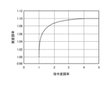
- FIG 4 is a diagram showing the relationship between the command modulation rate and the actual modulation rate in a typical inverter.
- the region where the command modulation rate shown on the horizontal axis exceeds 1 is the overmodulation region.
- the command modulation rate is a value indicating the ratio of the voltage command amplitude in the voltage command given to the inverter 30 to the DC voltage value applied to the inverter 30.
- the actual modulation rate shown on the vertical axis is a value indicating the ratio of the inverter output voltage to that DC voltage value.
- the relationship between the command modulation rate and the actual modulation rate has nonlinear characteristics.
- FIG. 5 is a diagram used to explain the modulation factor correction method, which is a technique for obtaining the characteristics shown in FIG. 4.
- the overmodulation region is a nonlinear region in which the relationship between the voltage command and the inverter output voltage is not proportional. For this reason, in this overmodulation region, as shown in FIG. 5, control is performed to obtain the intended inverter output voltage by multiplying a nonlinear modulation factor correction coefficient according to the value of the actual modulation factor.
- FIG. 6 is a block diagram showing an example of the configuration of the voltage command calculation unit 13 provided in the control device 10 according to the first embodiment.
- the voltage command calculation unit 13 includes adders 130, 132, 133, and 139, a speed controller 131, a d-axis current controller 134, a q-axis current controller 135, a frequency estimation unit 136, a voltage command amplitude calculation unit 137, a modulation rate correction coefficient calculation unit 138, and a command modulation rate and voltage phase calculation unit 140.
- the frequency estimation unit 136 estimates the frequency of the voltage applied to the motor 7 based on the d-axis current id, the q-axis current iq, the d-axis voltage command Vd*, and the q-axis voltage command Vq*, and outputs the frequency estimation value ⁇ est.
- the frequency estimation value ⁇ est output from the frequency estimation unit 136 to the outside of the voltage command calculation unit 13 in FIG. 6 is the frequency estimation value ⁇ est output from the voltage command calculation unit 13 to the electrical angle phase calculation unit 14 in FIG. 3.
- the adder/subtractor 130 subtracts the frequency estimation value ⁇ est from the frequency command ⁇ e*, and outputs the frequency deviation del_ ⁇ between the frequency command ⁇ e* and the frequency estimation value ⁇ est.
- the speed controller 131 calculates and outputs the q-axis current command iq* based on the frequency deviation del_ ⁇ .
- the q-axis current command iq* is the command value of the q-axis current iq that makes the frequency deviation del_ ⁇ zero, that is, the command value of the q-axis current iq that makes the frequency command ⁇ e* match the frequency estimated value ⁇ est.
- An example of the speed controller 131 is a Proportional-Integral (PI) controller, but is not limited to this example.
- the adder/subtracter 132 subtracts the d-axis current id from the d-axis current command id* and outputs the deviation (id*-id) between the d-axis current command id* and the d-axis current id.
- the d-axis current controller 134 performs PI control to converge the deviation (id*-id) between the d-axis current command id* and the d-axis current id to zero.
- the d-axis current controller 134 may perform reduction control to reduce pulsating components generated due to the dead time of the switching elements 311-316 of the inverter 30 and the induced voltage distortion of the motor 7, or may perform non-interference control to suppress mutual interference with the d-axis due to the q-axis current command iq*.
- the d-axis current controller 134 outputs the d-axis voltage command Vd* by PI control.
- the adder/subtractor 133 adds the q-axis current command iq* and the q-axis current compensation value iq_trq* obtained from the vibration suppression control unit 55, i.e., superimposes the q-axis current compensation value iq_trq* on the q-axis current command iq* to generate the q-axis current command iq**.
- the adder/subtractor 139 subtracts the q-axis current iq from the q-axis current command iq** and outputs the deviation (iq**-iq) between the q-axis current command iq** and the q-axis current iq.
- the q-axis current controller 135 performs PI control to converge the deviation (iq**-iq) between the q-axis current command iq** and the q-axis current iq to zero.
- the q-axis current controller 135 may perform reduction control to reduce pulsating components generated by the dead time of the switching elements 311 to 316 of the inverter 30 and the induced voltage distortion of the motor 7, or may perform non-interference control to suppress mutual interference with the q-axis due to the d-axis current command id*.
- the q-axis current controller 135 outputs the q-axis voltage command Vq* by PI control.
- the voltage command amplitude calculation unit 137 uses the d-axis voltage command Vd* and the q-axis voltage command Vq* to calculate the voltage command amplitude Vdq*_abs shown in the following equation (3).
- Vdq*_abs ⁇ (Vd* 2 +Vq* 2 ) ...(3)
- the voltage command amplitude Vdq*_abs calculated by the voltage command amplitude calculation unit 137 is divided by a value obtained by multiplying the bus voltage Vdc by 1/ ⁇ 2 and input to the modulation rate correction coefficient calculation unit 138.
- the modulation rate correction coefficient calculation unit 138 calculates the modulation rate correction coefficient K using the voltage command amplitude Vdq*_abs.
- the modulation rate correction coefficient calculation unit 138 holds a table of characteristics as shown in FIG. 5.
- the modulation rate correction coefficient calculation unit 138 recognizes the input value as a command modulation rate, and when the input value is 1 or less, sets the value of the modulation rate correction coefficient K to be multiplied by the command modulation rate to "1.0", and when the voltage command amplitude Vdq*_abs exceeds 1, sets and outputs the corresponding value of the modulation rate correction coefficient K.
- the means for realizing the modulation rate correction coefficient calculation unit 138 does not have to be a table.
- the modulation rate correction coefficient calculation unit 138 may be configured to determine the value of the modulation rate correction coefficient K corresponding to the command modulation rate by calculation processing.
- the d-axis voltage command Vd* is multiplied by the modulation rate correction coefficient K, and the multiplied value is output as the d-axis voltage command Vd**.
- the q-axis voltage command Vq* is multiplied by the modulation rate correction coefficient K, and the multiplied value is output as the q-axis voltage command Vq**.
- the d-axis voltage command Vd** and q-axis voltage command Vq** calculated by the voltage command calculation unit 13 are output to the command modulation rate and voltage phase calculation unit 140 inside the voltage command calculation unit 13.
- the d-axis voltage command Vd** and q-axis voltage command Vq** calculated by the voltage command calculation unit 13 are output to the excitation current command control unit 19 shown in FIG. 3 outside the voltage command calculation unit 13.
- FIG. 7 is a block diagram showing an example of the configuration of the command modulation rate and voltage phase calculation unit 140 provided in the voltage command calculation unit 13 according to the first embodiment.
- the command modulation rate and voltage phase calculation unit 140 includes a command modulation rate calculation unit 141 and a voltage phase calculation unit 144.
- the command modulation rate calculation unit 141 includes a voltage command amplitude calculation unit 142.
- the command modulation rate calculation unit 141 receives the d-axis voltage command Vd**, the q-axis voltage command Vq**, and the bus voltage Vdc.
- the voltage command amplitude calculation unit 142 uses the d-axis voltage command Vd** and the q-axis voltage command Vq** to calculate the voltage command amplitude Vdq**_abs shown in the following equation (4).
- Vdq**_abs ⁇ (Vd** 2 +Vq** 2 ) ...
- the voltage command amplitude Vdq**_abs calculated by the voltage command amplitude calculation unit 142 is divided by the bus voltage Vdc multiplied by 1/ ⁇ 2, and output as the command modulation factor M*.
- the voltage phase calculation unit 144 also uses the d-axis voltage command Vd** and the q-axis voltage command Vq** to calculate the voltage phase ⁇ v shown in the following equation (5).
- command modulation factor M* and voltage phase ⁇ v calculated by the command modulation factor and voltage phase calculation unit 140 are used by the space vector modulation unit 15.
- FIG. 8 is a block diagram showing an example of the configuration of the vibration suppression control unit 55 provided in the inverter control unit 12 according to the first embodiment.
- the vibration suppression control unit 55 includes a calculation unit 550, a cosine calculation unit 551, a sine calculation unit 552, multiplication units 553, 554, 561, and 562, low-pass filters 555 and 556, adders and subtractors 557, 558, and 563, and frequency control units 559 and 560.
- the compressor 50 is a single rotary compressor, scroll compressor, etc.
- the compressor 50 experiences a load torque pulsation once per mechanical angle period. Due to this load torque pulsation, the most dominant frequency component among the pulsation components contained in the capacitor output current i.d.c is the 1x component of the mechanical frequency, which is the operating frequency of the electric motor 7.
- the nx component of the mechanical frequency will be referred to as "machine nf”.
- the 1x component of the mechanical frequency would be "machine 1f", where n is an integer equal to or greater than 1.
- the frequency at which pulsation appears is expressed by the following equation (6).
- the power supply frequency is the frequency of the power supply voltage, and is generally 50 Hz or 60 Hz.
- m is an integer of 1 or more that represents an integer multiple of the power supply frequency.
- the m-th component of the power supply frequency will be referred to as "power supply mf”.
- the 1-times component of the power supply frequency is "power supply 1f”.
- the dominant component of the bus voltage Vdc is twice the power supply frequency, i.e., power supply 2f. Therefore, excluding machine 1f, the large components in the capacitor output current idc are
- the calculation unit 550 calculates the mechanical angle phase ⁇ mn indicating the rotational position of the electric motor 7 by integrating the frequency estimate value ⁇ est and dividing it by the number of pole pairs P.
- the cosine calculation unit 551 calculates the cosine value cos ⁇ mn based on the mechanical angle phase ⁇ mn.
- the sine calculation unit 552 calculates the sine value sin ⁇ mn based on the mechanical angle phase ⁇ mn.
- the multiplication unit 553 multiplies the frequency estimation value ⁇ est by the cosine value cos ⁇ mn to calculate the cosine component ⁇ est ⁇ cos ⁇ mn of the frequency estimation value ⁇ est.
- the multiplication unit 554 multiplies the frequency estimation value ⁇ est by the sine value sin ⁇ mn to calculate the sine component ⁇ est ⁇ sin ⁇ mn of the frequency estimation value ⁇ est.
- the cosine component ⁇ est ⁇ cos ⁇ mn and the sine component ⁇ est ⁇ sin ⁇ mn calculated by the multiplication units 553 and 554 contain not only a pulsating component with a frequency of ⁇ mn, but also pulsating components with frequencies higher than ⁇ mn, i.e., harmonic components.
- the low-pass filters 555 and 556 are first-order lag filters whose transfer function is expressed as 2/(1+s ⁇ Tf).
- s is the Laplace operator.
- Tf is a time constant, which is determined so as to remove pulsating components of frequencies higher than the frequency ⁇ mn. Note that "removal" includes cases where a part of the pulsating components is attenuated, i.e., reduced.
- the time constant Tf is set by the operation control unit 11 based on the speed command value, and the operation control unit 11 may notify the low-pass filters 555 and 556 of the time constant Tf, or the low-pass filters 555 and 556 may hold the time constant Tf.
- the first-order lag filter is just one example of the low-pass filters 555 and 556, and they may be moving average filters or the like, and the type of filter is not limited as long as it can remove the pulsating components on the high-frequency side.
- the low-pass filter 555 performs low-pass filtering on the cosine component ⁇ est ⁇ cos ⁇ mn to remove pulsating components with frequencies higher than ⁇ mn, and outputs the low-frequency component ⁇ est_c.
- the low-frequency component ⁇ est_c is a direct current quantity that represents the cosine component with a frequency of ⁇ mn among the pulsating components of the frequency estimate ⁇ est.
- the low-pass filter 556 performs low-pass filtering on the sine component ⁇ est ⁇ sin ⁇ mn to remove pulsating components with frequencies higher than ⁇ mn, and outputs the low-frequency component ⁇ est_s.
- the low-frequency component ⁇ est_s is a direct current quantity that represents the sine component with a frequency of ⁇ mn among the pulsating components of the frequency estimate ⁇ est.
- the adder/subtractor 557 calculates the difference ( ⁇ est_c-0) between the low-frequency component ⁇ est_c output from the low-pass filter 555 and zero.
- the adder/subtractor 558 calculates the difference ( ⁇ est_s-0) between the low-frequency component ⁇ est_s output from the low-pass filter 556 and zero.
- the frequency control unit 559 performs an integral operation on the difference ( ⁇ est_c-0) calculated by the adder/subtractor 557 to calculate the cosine component iq_trq_c of the current command that brings the difference ( ⁇ est_c-0) closer to zero. By generating the cosine component iq_trq_c in this way, the frequency control unit 559 performs control to make the low frequency component ⁇ est_c equal to zero.
- the integral operation here is just an example, and a proportional integral operation may be performed instead of the integral operation.
- the frequency control unit 560 performs an integral operation on the difference ( ⁇ est_s-0) calculated by the adder/subtractor 558 to calculate the sine component iq_trq_s of the current command that brings the difference ( ⁇ est_s-0) closer to zero. By generating the sine component iq_trq_s in this way, the frequency control unit 560 performs control to make the low frequency component ⁇ est_s match zero.
- the integral operation here is just an example, and a proportional integral operation may be performed instead of the integral operation.
- the multiplication unit 561 multiplies the cosine component iq_trq_c output from the frequency control unit 559 by the cosine value cos ⁇ mn to generate iq_trq_c ⁇ cos ⁇ mn.
- iq_trq_c ⁇ cos ⁇ mn is an AC component with a frequency n ⁇ est.
- the multiplication unit 562 multiplies the sine component iq_trq_s output from the frequency control unit 560 by the sine value sin ⁇ mn to generate iq_trq_s ⁇ sin ⁇ mn.
- iq_trq_s ⁇ sin ⁇ mn is an AC component with a frequency n ⁇ est.
- the adder/subtracter 563 calculates the sum of iq_trq_c ⁇ cos ⁇ mn output from the multiplier 561 and iq_trq_s ⁇ sin ⁇ mn output from the multiplier 562.
- the vibration suppression control unit 55 outputs the value calculated by the adder/subtracter 563 as the q-axis current compensation value iq_trq*.
- the vibration suppression control unit 55 shown in FIG. 8 is configured to suppress the pulsation of one frequency component with a frequency of ⁇ mn.
- multiple control systems with the configuration shown in FIG. 8 can be provided for each frequency component, and these multiple control systems can be connected in parallel.
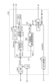
- FIG. 9 is a block diagram showing an example of the configuration of the excitation current command control unit 19 provided in the inverter control unit 12 according to the first embodiment.
- the excitation current command control unit 19 includes a voltage command amplitude calculation unit 191, adders 192 and 199, an MTPA (Maximum Torque Per Ampere) control unit 193, an FB (Feedback) flux weakening control unit 194, an id* comparison unit 195, a band elimination filter 196, a signal correction unit 197, and an FB auxiliary flux weakening control unit 198.
- the band elimination filter 196 and the FB flux weakening control unit 194 constitute a first controller 201
- the signal correction unit 197 and the FB auxiliary flux weakening control unit 198 constitute a second controller 202.
- the voltage command amplitude calculation unit 191 receives the d-axis voltage command Vd** and the q-axis voltage command Vq** as input.
- the d-axis voltage command Vd** and the q-axis voltage command Vq** are voltage commands after modulation factor correction.
- the voltage command amplitude calculation unit 191 uses the d-axis voltage command Vd** and the q-axis voltage command Vq** to calculate the voltage command amplitude Vdq**_abs shown in the above formula (4).
- the MTPA control unit 193 performs MTPA control on the q-axis current iq obtained from the coordinate conversion unit 18, and calculates the d-axis current command id*_MTPA, which is one of the d-axis current commands to be input to the id* comparison unit 195.
- the MTPA control adjusts the current phase of the current flowing through the electric motor 7 so as to maximize the torque generated by the electric motor 7.
- the MTPA control is well known, and since general MTPA control is used in this paper, a detailed explanation will be omitted here.
- the command modulation factor M is divided by 1/ ⁇ 2 times the bus voltage Vdc, and the divided value is input to an adder/subtractor 192 as a voltage limit value Vom*, which is a limit value for the d-axis and q-axis voltages.
- the voltage command amplitude Vdq**_abs calculated by the voltage command amplitude calculation unit 191 is input to the adder/subtractor 192.
- the adder/subtracter 192 calculates the deviation between the voltage limit value Vom* and the voltage command amplitude Vdq**_abs, and generates the calculated deviation as the voltage saturation amount ⁇ V.
- the voltage saturation amount ⁇ V is input to both the first controller 201 and the second controller 202.
- a signal correction unit 197 is provided in front of the FB auxiliary type flux-weakening control unit 198.
- the signal correction unit 197 multiplies the voltage saturation amount ⁇ V by "1/K", which is the reciprocal of the modulation factor correction coefficient K, and outputs the multiplied value to the FB auxiliary type flux-weakening control unit 198 as the correction value ⁇ V_a of the voltage saturation amount ⁇ V.
- FIG. 10 is a diagram used to explain why a signal correction unit 197 is required in front of the FB auxiliary type flux weakening control unit 198 provided in the excitation current command control unit 19 according to embodiment 1.
- the horizontal axis in Figure 10 is time, the solid line represents the command modulation rate calculated using the voltage command before modulation rate correction, and the dashed line represents the command modulation rate calculated using the voltage command after modulation rate correction.
- the number "1" is the boundary value of the command modulation rate at which flux-weakening control is performed.
- the region where the command modulation rate exceeds 1 is the overmodulation region, and the region where the command modulation rate is 1 or less is the non-overmodulation region.
- the waveform shown by the dashed line in FIG. 10 has a large value only in the overmodulation region due to the modulation factor correction of the first embodiment. Therefore, if the waveform shown by the dashed line is used, the value of the voltage saturation amount ⁇ V in the overmodulation region will not be appropriate.
- the waveform shown by the solid line is calculated using the voltage command before the modulation factor correction, so the value of the voltage saturation amount ⁇ V is appropriate in both the overmodulation region and the non-overmodulation region. Therefore, in order to use an appropriate value of the voltage saturation amount ⁇ V, a signal correction unit 197 is provided in front of the FB auxiliary type flux weakening control unit 198.
- the output of the FB auxiliary type flux weakening control unit 198 becomes the intended control amount.
- the modulation factor correction coefficient K used in the signal correction unit 197 the value of the modulation factor correction coefficient K calculated by the modulation factor correction coefficient calculation unit 138 shown in FIG. 6 can be used.
- the response speed of the FB flux-weakening control unit 194 provided in the first controller 201 is set to about 1/10 of the response speed of the current control.
- the response speed of the FB auxiliary flux-weakening control unit 198 provided in the second controller 202 is set to be faster than the response speed of the FB flux-weakening control unit 194 and is desirably set to 1/3 or less, more desirably 1/5 or less, of the response speed of the vibration suppression control.
- the FB flux-weakening control unit 194 can be operated as a controller that compensates for steady-state voltage saturation
- the FB auxiliary flux-weakening control unit 198 can be operated as a controller that reduces frequency components synchronized with the pulsation of the q-axis current.
- the first controller 201 is configured as a controller that controls the DC component in the voltage saturation amount ⁇ V
- the second controller 202 is configured as a controller that controls the AC component in the voltage saturation amount ⁇ V.
- the band-rejection filter 196 is not an essential component, but is provided to effectively reduce the frequency components compensated for by the FB auxiliary type flux-weakening control unit 198, i.e., frequency components synchronized with the pulsation of the q-axis current.
- the FB flux weakening control unit 194 can output a suitable control amount for compensating for the DC component, which is the steady voltage saturation amount in the voltage saturation amount ⁇ V.
- the FB auxiliary flux weakening control unit 198 can output a suitable control amount for compensating for the AC component synchronized with the pulsation of the q-axis current in the voltage saturation amount ⁇ V.
- the FB flux-weakening control unit 194 integrates the output of the band-elimination filter 196 to calculate the d-axis current command id*_FB1, which is another d-axis current command to be input to the id* comparison unit 195.
- the integral gain Kfw of the FB flux-weakening control unit 194 is set by the following equation (7).
- ⁇ fw is the cutoff angular frequency when the FB flux-weakening control unit 194 is viewed as a low-pass filter
- Ld is the d-axis inductance
- ⁇ e is the angular frequency of the inverter output voltage, as described above.
- the integral control gain in flux-weakening control is ⁇ fw/( ⁇ eLd), but in the excitation current command control unit 19 in embodiment 1, the voltage command after modulation factor correction is used to perform flux-weakening control, so the modulation factor correction coefficient K is required in the denominator of the integral gain Kfw, as in equation (7) above.
- the integral gain Kfw shown in equation (7) above it is possible to stabilize operation in the overmodulation region even when the modulation factor correction method and flux-weakening control are combined.
- the FB auxiliary type flux-weakening control unit 198 integrates the output of the band elimination filter 196 to calculate the d-axis current command id*_FB2, which is another d-axis current command to be input to the id* comparison unit 195.
- the FB auxiliary type flux-weakening control unit 198 will be further described with reference to FIG. 11.
- FIG. 11 is a block diagram showing an example of the configuration of the FB auxiliary type flux-weakening control unit 198 provided in the excitation current command control unit 19 according to the first embodiment.
- the FB auxiliary type flux-weakening control unit 198 includes multiplication units 601, 602, 610, and 611, low-pass filters 603 and 604, adders and subtractors 605, 606, and 612, integral controllers 607 and 608, and a limit processing unit 609.
- Multiplication unit 601 multiplies the correction value ⁇ V_a of the voltage saturation amount ⁇ V by the cosine value cos ⁇ mn, and multiplication unit 602 multiplies the correction value ⁇ V_a of the voltage saturation amount ⁇ V by the sine value sin ⁇ mn.
- the outputs of multiplication units 601 and 602 contain pulsation components of angular frequencies higher than the angular frequency ⁇ mn, in addition to the pulsation component of angular frequency ⁇ mn.
- the low-pass filters 603 and 604 are first-order lag filters whose transfer function is expressed as 2/(1+s ⁇ Ta).
- s is the Laplace operator.
- Ta is a time constant, which is determined so as to remove pulsating components of frequencies higher than the angular frequency ⁇ mn. Note that "removal" includes cases where a part of the pulsating components is attenuated, i.e., reduced.
- the time constant Ta is set by the operation control unit 11 based on the speed command value, and the operation control unit 11 may notify the low-pass filters 603 and 604 of the time constant Ta, or the low-pass filters 603 and 604 may hold the time constant Ta.
- the first-order lag filter is just one example of the low-pass filters 603 and 604, and they may be moving average filters or the like, and the type of filter is not limited as long as it can remove the pulsating components on the high-frequency side.
- the low-pass filter 603 performs low-pass filtering on the output of the multiplication unit 601 to remove pulsating components with frequencies higher than the angular frequency ⁇ mn, and outputs the low-frequency component ⁇ V_a_c.
- the low-frequency component ⁇ V_a_c is a direct current amount that represents the cosine component with an angular frequency of ⁇ mn among the pulsating components of the correction value ⁇ V_a of the voltage saturation amount ⁇ V.
- the low-pass filter 604 performs low-pass filtering on the output of the multiplication unit 602 to remove pulsating components with frequencies higher than the angular frequency ⁇ mn, and outputs the low-frequency component ⁇ V_a_s.
- the low-frequency component ⁇ V_a_s is a direct current amount that represents the sine component with an angular frequency of ⁇ mn among the pulsating components of the correction value ⁇ V_a of the voltage saturation amount ⁇ V.
- Adder-subtractor 605 calculates the difference ( ⁇ V_a_c-0) between the low-frequency component ⁇ V_a_c output from low-pass filter 603 and zero.
- Adder-subtractor 606 calculates the difference ( ⁇ V_a_s-0) between the low-frequency component ⁇ V_a_s output from low-pass filter 604 and zero.
- the integral controller 607 performs an integral operation on the difference ( ⁇ V_a_c-0) calculated by the adder/subtractor 605 to calculate the cosine component id_FB_c of the d-axis current command that brings the difference ( ⁇ V_a_c-0) closer to zero.
- the integral controller 607 performs control to make the low frequency component ⁇ V_a_c equal to zero.
- the integral operation here is just an example, and a proportional integral operation may be performed instead of the integral operation.
- the integral controller 608 performs an integral operation on the difference ( ⁇ V_a_s-0) calculated by the adder/subtractor 606 to calculate the sine component id_FB_s of the d-axis current command that brings the difference ( ⁇ V_a_s-0) closer to zero. By generating the sine component id_FB_s in this way, the integral controller 608 performs control to make the low frequency component ⁇ V_a_s equal to zero.
- the integral operation here is just an example, and a proportional integral operation may be performed instead of the integral operation.
- the integral gain Kfw_a of the integral controllers 607, 608 in the FB assisted flux weakening control unit 198 is set by the following equation (8).
- ⁇ fw_a is the cutoff angular frequency when the integral controllers 607, 608 are viewed as a low-pass filter.
- Ld and ⁇ e are the angular frequencies of the d-axis inductance and inverter output voltage described above.
- the response speed of the FB auxiliary type flux-weakening control unit 198 is set to 1 ⁇ 3 or less or 1 ⁇ 5 or less of the response speed of the vibration suppression control, so the integral gain Kfw_a of the integral controllers 607, 608 is set to satisfy these criteria.
- the control of the FB flux weakening control unit 194 is prioritized over the FB auxiliary flux weakening control unit 198.
- the d-axis current command that controls the DC component of the voltage saturation amount ⁇ V is set with priority over the d-axis current command that controls the AC component of the voltage saturation amount ⁇ V.
- the multiplier 610 multiplies the limit cosine component id_FB_c_lim output from the limit processor 609 by a cosine value cos ⁇ mn and outputs the result, and the multiplier 611 multiplies the limit sine component id_FB_s_lim output from the limit processor 609 by a sine value sin ⁇ mn and outputs the result.
- the adder/subtracter 612 adds the output of the multiplier 610 and the output of the multiplier 611, and outputs the sum as the d-axis current command id*_FB2.
- the adder/subtractor 199 receives the d-axis current command id*_FB1 generated by the FB flux-weakening control unit 194 and the d-axis current command id*_FB2 generated by the FB auxiliary flux-weakening control unit 198.
- the adder/subtractor 199 adds the d-axis current command id*_FB1 and the d-axis current command id*_FB2, and outputs the sum to the id* comparison unit 195 as the d-axis current command id*_FB.
- the id* comparison unit 195 selects the larger negative value from the d-axis current command id*_MTPA output from the MTPA control unit 193 and the d-axis current command id*_FB output from the adder/subtractor 199, and outputs the selected value as the d-axis current command id* to the voltage command calculation unit 13.
- FIG. 12 is a diagram illustrating a method for setting the limiter value id_FB_lim set in the FB assisted flux weakening control unit 198 shown in FIG. 11.
- FIG. 13 is a flowchart illustrating the procedure for setting the limiter value id_FB_lim set in the FB assisted flux weakening control unit 198 shown in FIG. 11.
- FIG. 12 shows a state in which the magnitude of the average voltage command Vave* is the voltage limit value Vom*, and the tip of the vector average voltage command Vave* is located on the voltage limit circle 22.
- the calculation of the average voltage command Vave* uses, for example, the voltage command amplitude Vdq**_abs calculated by the voltage command amplitude calculation unit 142, but not the voltage command amplitude Vdq*_abs calculated by the voltage command amplitude calculation unit 137.
- the calculation of the average voltage command Vave* uses the voltage command before modulation rate correction, not the voltage command after modulation rate correction. All other vector components shown in FIG. 12 are also converted to values before modulation rate correction.
- ⁇ Vq means the transient shortage of the q-axis voltage, and will be referred to as the "q-axis voltage shortage" below.
- the value of the q-axis voltage shortage ⁇ Vq is negative, meaning that the q-axis voltage is insufficient.
- the value of the q-axis voltage shortage ⁇ Vq is positive, meaning that the q-axis voltage is sufficient.
- the q-axis voltage deficiency amount ⁇ Vq is calculated using the procedure shown in FIG. 13, and the limiter value id_FB_lim is set based on the q-axis voltage deficiency amount ⁇ Vq.
- the procedure for setting the limiter value id_FB_lim will be described below with reference to FIG. 13.
- the control device 10 performs low-pass filtering on the q-axis voltage command Vq* (step S11). By performing low-pass filtering on the q-axis voltage command Vq*, the q-axis voltage change component that appears in the q-axis direction due to the pulsating component ⁇ id of the d-axis current is reduced in the output after filtering.
- the control device 10 uses the output after filtering to calculate the q-axis component Vqconv* of the dq-axis voltage command Vconv* shown in the following equation (9).
- the control device 10 performs low-pass filtering on the d-axis voltage command Vd* (step S12).
- step S12 By performing low-pass filtering on the d-axis voltage command Vd*, the d-axis voltage change component that appears in the d-axis direction due to the pulsating component ⁇ iq of the q-axis current is reduced in the output after filtering.
- the control device 10 adds the amount of change in the d-axis voltage due to the load torque pulsation suppression control to the filter value of the d-axis voltage command Vd* (step S13). This process calculates the d-axis component Vdconv* of the dq-axis voltage command Vconv* shown in the following equation (10).
- Vdconv* -
- Vdconv* -
- the control device 10 calculates the required q-axis voltage command vqlim required to realize the d-axis voltage command Vdconv* during load torque pulsation suppression control within the range of the voltage limit circle 22 (step S14).
- the required q-axis voltage command vqlim can be calculated using the following equation (12) according to Pythagoras' theorem.
- Vqlim ⁇ (Vom*) 2 - (Vdconv*) 2 ⁇ ...(12)
- the control device 10 calculates the q-axis voltage shortage ⁇ Vq that needs to be reduced in order to make the q-axis voltage Vqconv*, which takes into account only the d-axis current id of the DC component, the required q-axis voltage command Vqlim (step S15).
- the q-axis voltage shortage ⁇ Vq can be calculated using the following formula (13).
- the control device 10 converts the q-axis voltage deficiency ⁇ Vq into the amplitude value id_lim_buf of the d-axis current id (step S16).
- the amplitude value id_lim_buf of the d-axis current id can be calculated using the following formula (14).
- id_lim_buf ⁇ Vq/( ⁇ eLd)...(14)
- the control device 10 prioritizes the d-axis current command id_FB1 based on the FB flux-weakening control and calculates the limiter value id_FB_lim taking into account the current margin (step S17).
- the processing of step S17 will be explained using the following formula (15).
- the control device 10 determines whether the amplitude value id_lim_buf of the d-axis current id is positive or negative. If the amplitude value id_lim_buf is equal to or greater than zero, the limiter value id_FB_lim is set to zero.
- the control device 10 sets the absolute value of the amplitude value id_lim_buf to the temporary limiter value id_lim. Then, the control device 10 sets the minimum value of the limiter value id_FB_lim to zero, and sets the maximum value of the limiter value id_FB_lim to "id_lim-id_FB1".
- the reason for subtracting the d-axis current command id_FB1 by the FB flux-weakening control from the temporary limiter value id_lim is to prioritize control by the d-axis current command id_FB1, that is, to prioritize flux-weakening control for the DC component.
- the flux-weakening control for the AC component by the FB auxiliary flux-weakening control unit 198 is control that utilizes the remaining current margin obtained by subtracting the control amount by the FB flux-weakening control unit 194 from the total current margin, and therefore efficient and stable control can be performed.
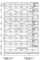
- Fig. 14 is a diagram showing how various torques, command values and operating values of various currents, command values and operating values of various voltages, and command modulation rates and actual modulation rates change when the excitation current command control unit 19 shown in Fig. 9 does not include the FB auxiliary type flux-weakening control unit 198 and only includes the FB flux-weakening control unit 194.
- Fig. 15 is a diagram showing how various torques, command values and operating values of various currents, command values and operating values of various voltages, and command modulation rates and actual modulation rates change when the excitation current command control unit 19 shown in Fig. 9 includes both the FB auxiliary type flux-weakening control unit 198 and the FB flux-weakening control unit 194.
- Figures 14 and 15 from top to bottom, the waveforms of speed (estimated speed, command value, actual speed), torque (load torque, motor torque), current (three-phase current: Iu, Iv, Iw), current (d-axis current command, d-axis current, limiter value), current (q-axis current command, q-axis current), voltage (d-axis voltage command, d-axis voltage), voltage (q-axis voltage command, q-axis voltage), command modulation rate, and actual modulation rate are shown.
- the horizontal axis in Figures 14 and 15 is time.
- Figures 14 and 15 both show operating waveforms when the command modulation rate (command modulation rate M) is set to 1.1. That is, in Figures 14 and 15, both are set to operate with a command modulation rate M of 1.1.
- the distinctive features of these operating waveforms are as follows:
- the power conversion device includes a converter that rectifies the power supply voltage applied from an AC power supply, a capacitor connected to the output terminal of the converter, an inverter connected to both ends of the capacitor, and a control device that performs vibration suppression control that controls the operation of the inverter to suppress vibration of the load.
- the control device calculates an excitation current command used in the flux-weakening control based on a voltage saturation amount calculated from a voltage limit value determined by a DC voltage value applied to the inverter and a voltage command given to the inverter.
- the voltage saturation amount is divided into a DC component and an AC component, and the excitation current command is generated based on a first excitation current command calculated based on the DC component and a second excitation current command calculated based on the AC component.
- the DC component is controlled to compensate for steady-state voltage saturation, and the AC component is controlled to reduce frequency components synchronized with the pulsation of the torque current.
- the response speed of the control response that controls the AC component is preferably set to 1 ⁇ 3 or less, and more preferably 1 ⁇ 5 or less, of the response speed of the vibration suppression control. With this configuration, it becomes possible to suitably design the controller that controls the AC component in relation to the controller that performs the vibration suppression control.
- the voltage saturation amount is controlled so that the peak value of the actual modulation rate falls within a range of +2% with respect to the average value of the actual modulation rate, which is a value indicating the ratio of the inverter output voltage to the DC voltage value. If the peak value of the actual modulation rate can be controlled in this way, it becomes possible to reduce the current distortion of the torque current while performing vibration suppression control even in the overmodulation region.
- the control device performs modulation factor correction in a region where the command modulation factor, which indicates the ratio of the voltage command amplitude in the voltage command given to the inverter to the DC voltage value applied to the inverter, exceeds 1.
- the control device is configured to determine the excitation current command for flux-weakening control from the voltage command after modulation factor correction
- the controller is configured so that the corrected voltage saturation amount after modulation factor correction is input to the controller that controls the DC component, and the voltage saturation amount converted to the value before modulation factor correction is input to the controller that controls the AC component.
- the gain of the flux-weakening control in the FB flux-weakening control unit is an important parameter for stabilizing the operation of the control device.
- the control device is configured to determine the excitation current command for the flux-weakening control from the voltage command after modulation factor correction, as in the first embodiment, it is desirable to set the gain of the flux-weakening control including the modulation factor correction coefficient. Configuring the control device with this in mind can contribute to stabilizing the operation of the control device.
- FIG. 16 is a diagram showing an example of a hardware configuration realizing the control device 10 provided in the power conversion device 300 according to the first embodiment.
- the control device 10 is realized by a processor 501 and a memory 502.
- the processor 501 is a CPU (Central Processing Unit), central processing unit, processing unit, arithmetic unit, microprocessor, microcomputer, processor, DSP (Digital Signal Processor), or system LSI (Large Scale Integration).
- Examples of the memory 502 include non-volatile or volatile semiconductor memories such as RAM (Random Access Memory), ROM (Read Only Memory), flash memory, EPROM (Erasable Programmable Read Only Memory), and EEPROM (registered trademark) (Electrically Erasable Programmable Read-Only Memory).
- the memory 502 is not limited to these, and may be a magnetic disk, optical disk, compact disk, mini disk, or DVD (Digital Versatile Disc).
- Embodiment 2 a control device configured using a method for performing flux-weakening control using a voltage command after modulation factor correction is described. In the second embodiment, a control device configured using a method for performing flux-weakening control using a voltage command before modulation factor correction is described.
- FIG. 17 is a block diagram showing an example of the configuration of a control device 10A included in a power conversion device 300 according to the second embodiment.
- the control device 10A includes an operation control unit 11 and an inverter control unit 12A.
- the inverter control unit 12A includes a voltage command calculation unit 13A, an electrical angle phase calculation unit 14, a space vector modulation unit 15, a PWM signal generation unit 16, a current restoration unit 17, a coordinate conversion unit 18, an excitation current command control unit 19A, and a vibration suppression control unit 55.
- components having different functions from the control device 10 of the first embodiment shown in FIG. 3 are indicated with the subscript A.
- FIGS. 18, 19, and 20 the second embodiment will be described with a focus on the functions of the components that are different from those of the first embodiment.
- the excitation current command control unit 19A generates a d-axis current command id*, which is an excitation current command, based on the q-axis current iq acquired from the coordinate conversion unit 18, the command modulation factor M acquired from the operation control unit 11, and the d-axis voltage command Vd* and the q-axis voltage command Vq* calculated by the voltage command calculation unit 13A.
- the excitation current command control unit 19A obtains a current phase angle at which the output torque of the motor 7 is equal to or greater than a set value or is at its maximum value, and calculates the d-axis current command id* based on the obtained current phase angle.
- the excitation current command control unit 19A When calculating the d-axis current command id*, the excitation current command control unit 19A performs flux-weakening control and command modulation factor correction to determine the d-axis current command id*. The specific configuration and operation of the excitation current command control unit 19A will be described later.
- the excitation current command control unit 19A may calculate the d-axis current command id* using the motor current flowing through the motor 7 instead of the output torque of the motor 7. In this case, the d-axis current command id* is calculated based on the current phase angle at which the motor current flowing through the motor 7 is equal to or less than the set value or is at its minimum value.
- the voltage command calculation unit 13A generates the d-axis voltage command Vd*, the q-axis voltage command Vq*, the frequency estimate ⁇ est, the command modulation factor M**, and the voltage phase ⁇ v based on the frequency command ⁇ e* obtained from the operation control unit 11, the d-axis current id and the q-axis current iq obtained from the coordinate conversion unit 18, the d-axis current command id* obtained from the excitation current command control unit 19A, and the q-axis current compensation value iq_trq* obtained from the vibration suppression control unit 55.
- the command modulation factor M** and the voltage phase ⁇ v are used in the space vector modulation unit 15, the d-axis voltage command Vd* and the q-axis voltage command Vq* are used in the excitation current command control unit 19A, and the frequency estimate ⁇ est is used inside the electrical angle phase calculation unit 14 and the voltage command calculation unit 13A.
- FIG. 18 is a block diagram showing an example of the configuration of a voltage command calculation unit 13A provided in a control device 10A according to embodiment 2.
- the voltage command calculation unit 13A includes adders 130, 132, 133, and 139, a speed controller 131, a d-axis current controller 134, a q-axis current controller 135, a frequency estimation unit 136, and a command modulation rate and voltage phase calculation unit 140A.
- the d-axis voltage command Vd* and q-axis voltage command Vq* calculated by the voltage command calculation unit 13A are output to the command modulation rate and voltage phase calculation unit 140A inside the voltage command calculation unit 13A. Also, the d-axis voltage command Vd* and q-axis voltage command Vq* calculated by the voltage command calculation unit 13A are output to the excitation current command control unit 19A shown in FIG. 17 outside the voltage command calculation unit 13A.
- FIG. 19 is a block diagram showing an example of the configuration of a command modulation rate and voltage phase calculation unit 140A included in a voltage command calculation unit 13A according to embodiment 2.
- the command modulation rate and voltage phase calculation unit 140A includes a command modulation rate calculation unit 141A and a voltage phase calculation unit 144A.
- the command modulation rate calculation unit 141A also includes a voltage command amplitude calculation unit 142A and a command modulation rate correction unit 146A.
- the command modulation rate calculation unit 141A receives the d-axis voltage command Vd*, the q-axis voltage command Vq*, and the bus voltage Vdc.
- the voltage command amplitude calculation unit 142A uses the d-axis voltage command Vd* and the q-axis voltage command Vq* to calculate the voltage command amplitude Vdq*_abs shown in the following equation (16).
- Vdq*_abs ⁇ (Vd* 2 +Vq* 2 ) ...(16)
- the voltage command amplitude Vdq*_abs calculated by the voltage command amplitude calculation unit 142A is divided by the bus voltage Vdc multiplied by 1/ ⁇ 2, and input to the command modulation factor correction unit 146A as the command modulation factor M*.
- the command modulation factor M* input to the command modulation factor correction unit 146A is calculated using the voltage command before modulation factor correction.
- the command modulation factor correction unit 146A has a table equivalent to that of the modulation factor correction coefficient calculation unit 138. If the value of the command modulation factor M* input is 1 or less, the command modulation factor correction unit 146A outputs the value of the command modulation factor M* as is, and if the value of the command modulation factor M* exceeds 1, it multiplies the command modulation factor M* by the corresponding modulation factor correction coefficient K and outputs the multiplied value as the command modulation factor M**.
- the voltage phase calculation unit 144A uses the d-axis voltage command Vd* and the q-axis voltage command Vq* to calculate the voltage phase ⁇ v shown in the following equation (17).
- the command modulation rate M** and voltage phase ⁇ v calculated by the command modulation rate and voltage phase calculation unit 140A are used by the space vector modulation unit 15.
- FIG. 20 is a block diagram showing an example of the configuration of an excitation current command control unit 19A provided in an inverter control unit 12A according to the second embodiment.
- the excitation current command control unit 19A includes a command modulation rate correction unit 190A, a voltage command amplitude calculation unit 191A, adders and subtractors 192 and 199, an MTPA control unit 193, an FB flux weakening control unit 194A, an id* comparison unit 195, a band elimination filter 196, and an FB auxiliary flux weakening control unit 198A.
- the band elimination filter 196 and the FB flux weakening control unit 194A constitute a first controller 201A
- the FB auxiliary flux weakening control unit 198A constitutes a second controller 202A.
- the d-axis voltage command Vd* and the q-axis voltage command Vq* are input to the voltage command amplitude calculation unit 191A.
- the voltage command amplitude calculation unit 191A uses the d-axis voltage command Vd* and the q-axis voltage command Vq* to calculate the voltage command amplitude Vdq*_abs shown in the above formula (16).
- the MTPA control unit 193 performs MTPA control on the q-axis current iq obtained from the coordinate conversion unit 18, and calculates one of the d-axis current commands id*_MTPA to be input to the id* comparison unit 195.
- Command modulation factor correction unit 190A has a table equivalent to that of command modulation factor correction unit 146A.
- command modulation factor correction unit 190A When the value of the command modulation factor M input is 1 or less, command modulation factor correction unit 190A outputs the value of command modulation factor M as is, and when the value of command modulation factor M exceeds 1, it multiplies the command modulation factor M by the reciprocal 1/k of the corresponding modulation factor correction coefficient K and outputs the multiplied value.
- the command modulation factor M is multiplied by the reciprocal 1/k in order to align the comparison level with the voltage command amplitude Vdq*_abs output from voltage command amplitude calculation unit 191A. In other words, since the voltage command amplitude Vdq*_abs is generated using the voltage command before modulation factor correction, the command modulation factor M is multiplied by the reciprocal 1/k in relation to this process.
- the output of the command modulation rate correction unit 190A is divided by 1/ ⁇ 2 times the bus voltage Vdc, and the divided value is input to an adder/subtractor 192 as a voltage limit value Vom*, which is a limit value for the d-axis and q-axis voltages.
- the voltage command amplitude Vdq*_abs calculated by the voltage command amplitude calculation unit 191A is input to the adder/subtractor 192.
- the adder/subtractor 192 calculates the deviation between the voltage limit value Vom* and the voltage command amplitude Vdq*_abs, and generates the calculated deviation as a voltage saturation amount ⁇ V'.
- the voltage saturation amount ⁇ V' is input to both the first controller 201A and the second controller 202A.
- the voltage saturation amount ⁇ V' is generated using the d-axis voltage command Vd* and the q-axis voltage command Vq*, which are voltage commands before modulation rate correction. Therefore, unlike the first embodiment, the signal correction unit 197 provided in the stage preceding the FB auxiliary type flux-weakening control unit 198 is not necessary.
- the FB flux-weakening control unit 194A integrates the output of the band-elimination filter 196 to calculate the d-axis current command id*_FB1, which is another d-axis current command to be input to the id* comparison unit 195.
- the integral gain Kfw of the FB flux-weakening control unit 194A is set by the following equation (18).
- ⁇ fw is the cutoff angular frequency when the FB flux-weakening control unit 194A is viewed as a low-pass filter
- Ld is the d-axis inductance
- ⁇ e is the angular frequency of the inverter output voltage, as described above.
- the voltage command after modulation factor correction is used to perform flux-weakening control, so the modulation factor correction coefficient K was required in the denominator of the integral gain Kfw as in the above formula (7).
- the voltage command before modulation factor correction is used to perform flux-weakening control, so the modulation factor correction coefficient K is not required as in the above formula (18).
- the integral gain is set using the modulation factor correction coefficient K as in the excitation current command control unit 19 in the first embodiment, the operation becomes unstable. Therefore, by using the integral gain Kfw shown in the above formula (18), it is possible to stabilize the operation in the overmodulation region even when the modulation factor correction method and flux-weakening control are combined.
- the FB auxiliary type flux-weakening control unit 198A calculates the d-axis current command id*_FB2, which is another d-axis current command input to the id* comparison unit 195, by integrating the voltage saturation amount ⁇ V'.
- the adder/subtractor 199 receives the d-axis current command id*_FB1 generated by the FB flux-weakening control unit 194A and the d-axis current command id*_FB2 generated by the FB auxiliary flux-weakening control unit 198A.
- the adder/subtractor 199 adds the d-axis current command id*_FB1 and the d-axis current command id*_FB2, and outputs the sum to the id* comparison unit 195 as the d-axis current command id*_FB.
- the id* comparison unit 195 selects the larger negative value from the d-axis current command id*_MTPA output from the MTPA control unit 193 and the d-axis current command id*_FB output from the adder/subtractor 199, and outputs the selected value as the d-axis current command id* to the voltage command calculation unit 13A.
- the power conversion device includes a converter that rectifies the power supply voltage applied from the AC power supply, a capacitor connected to the output terminal of the converter, an inverter connected to both ends of the capacitor, and a control device that performs vibration suppression control that controls the operation of the inverter to suppress vibration of the load.
- the control device calculates an excitation current command used in the flux-weakening control based on a voltage saturation amount calculated from a voltage limit value determined by a DC voltage value applied to the inverter and a voltage command given to the inverter.
- the voltage saturation amount is divided into a DC component and an AC component, and the excitation current command is generated based on a first excitation current command calculated based on the DC component and a second excitation current command calculated based on the AC component.
- the control device according to the second embodiment performs flux-weakening control using a voltage command before modulation factor correction. Even when the power conversion device according to the second embodiment is used, the effects according to the first embodiment can be enjoyed. That is, when the power conversion device according to the second embodiment is used, even when vibration suppression control and flux-weakening control are combined, it is possible to perform sufficient flux-weakening control in the overmodulation region.
- the gain of the flux-weakening control in the FB flux-weakening control unit is an important parameter for stabilizing the operation of the control device.
- the control device is configured to determine the excitation current command for the flux-weakening control from the voltage command before modulation factor correction, as in the second embodiment, it is desirable to set the gain of the flux-weakening control without including the modulation factor correction coefficient. Configuring the control device with this in mind can contribute to stabilizing the operation of the control device.
- Fig. 21 is a diagram showing a configuration example of a refrigeration cycle-applied device 900 according to embodiment 3.
- the refrigeration cycle-applied device 900 according to embodiment 3 includes the power conversion device 300 described in embodiment 1 or embodiment 2.
- the refrigeration cycle-applied device 900 according to embodiment 3 can be applied to products including a refrigeration cycle, such as air conditioners, refrigerators, freezers, and heat pump water heaters.
- a refrigeration cycle such as air conditioners, refrigerators, freezers, and heat pump water heaters.
- components having the same functions as those in embodiment 1 and the like are denoted by the same reference numerals as those in embodiment 1.
- the refrigeration cycle application device 900 includes a compressor 50 incorporating the electric motor 7 in the first or second embodiment, a four-way valve 902, an indoor heat exchanger 906, an expansion valve 908, and an outdoor heat exchanger 910, which are attached via a refrigerant pipe 912.
- the refrigeration cycle device 900 can perform heating or cooling operation by switching the four-way valve 902.
- the compression mechanism 52 is driven by a variable speed controlled electric motor 7.
- the refrigerant is pressurized by the compression mechanism 52 and sent out, passes through the four-way valve 902, the indoor heat exchanger 906, the expansion valve 908, the outdoor heat exchanger 910, and the four-way valve 902, and returns to the compression mechanism 52.
- the refrigerant is pressurized by the compression mechanism 52 and sent out, passes through the four-way valve 902, the outdoor heat exchanger 910, the expansion valve 908, the indoor heat exchanger 906, and the four-way valve 902, and returns to the compression mechanism 52.
- the indoor heat exchanger 906 acts as a condenser to release heat, and the outdoor heat exchanger 910 acts as an evaporator to absorb heat.
- the outdoor heat exchanger 910 acts as a condenser to release heat, and the indoor heat exchanger 906 acts as an evaporator to absorb heat.
- the expansion valve 908 reduces the pressure of the refrigerant to expand it.
Landscapes
- Engineering & Computer Science (AREA)
- Power Engineering (AREA)
- Control Of Ac Motors In General (AREA)
Priority Applications (2)
| Application Number | Priority Date | Filing Date | Title |
|---|---|---|---|
| PCT/JP2023/034924 WO2025069183A1 (ja) | 2023-09-26 | 2023-09-26 | 電力変換装置、電動機駆動装置及び冷凍サイクル適用機器 |
| JP2025548063A JPWO2025069183A1 (https=) | 2023-09-26 | 2023-09-26 |
Applications Claiming Priority (1)
| Application Number | Priority Date | Filing Date | Title |
|---|---|---|---|
| PCT/JP2023/034924 WO2025069183A1 (ja) | 2023-09-26 | 2023-09-26 | 電力変換装置、電動機駆動装置及び冷凍サイクル適用機器 |
Publications (1)
| Publication Number | Publication Date |
|---|---|
| WO2025069183A1 true WO2025069183A1 (ja) | 2025-04-03 |
Family
ID=95202583
Family Applications (1)
| Application Number | Title | Priority Date | Filing Date |
|---|---|---|---|
| PCT/JP2023/034924 Pending WO2025069183A1 (ja) | 2023-09-26 | 2023-09-26 | 電力変換装置、電動機駆動装置及び冷凍サイクル適用機器 |
Country Status (2)
| Country | Link |
|---|---|
| JP (1) | JPWO2025069183A1 (https=) |
| WO (1) | WO2025069183A1 (https=) |
Cited By (1)
| Publication number | Priority date | Publication date | Assignee | Title |
|---|---|---|---|---|
| JP7825794B1 (ja) * | 2025-07-11 | 2026-03-06 | 三菱電機株式会社 | 電力変換装置、モータ駆動装置および冷凍サイクル適用機器 |
Citations (5)
| Publication number | Priority date | Publication date | Assignee | Title |
|---|---|---|---|---|
| JP2010288359A (ja) * | 2009-06-11 | 2010-12-24 | Hitachi Appliances Inc | インバータの制御装置、及び、それを用いた空調機,洗濯機 |
| JP2011083112A (ja) * | 2009-10-07 | 2011-04-21 | Toyo Electric Mfg Co Ltd | 永久磁石型三相交流電動機の制御装置 |
| JP5791848B2 (ja) * | 2013-04-10 | 2015-10-07 | 三菱電機株式会社 | 永久磁石型モータの制御装置 |
| JP2017158415A (ja) * | 2016-03-04 | 2017-09-07 | 株式会社富士通ゼネラル | モータ制御装置 |
| JP2022119473A (ja) * | 2021-02-04 | 2022-08-17 | オムロン株式会社 | 演算装置、電動機の制御装置、演算方法、制御方法、およびプログラム |
-
2023
- 2023-09-26 WO PCT/JP2023/034924 patent/WO2025069183A1/ja active Pending
- 2023-09-26 JP JP2025548063A patent/JPWO2025069183A1/ja active Pending
Patent Citations (5)
| Publication number | Priority date | Publication date | Assignee | Title |
|---|---|---|---|---|
| JP2010288359A (ja) * | 2009-06-11 | 2010-12-24 | Hitachi Appliances Inc | インバータの制御装置、及び、それを用いた空調機,洗濯機 |
| JP2011083112A (ja) * | 2009-10-07 | 2011-04-21 | Toyo Electric Mfg Co Ltd | 永久磁石型三相交流電動機の制御装置 |
| JP5791848B2 (ja) * | 2013-04-10 | 2015-10-07 | 三菱電機株式会社 | 永久磁石型モータの制御装置 |
| JP2017158415A (ja) * | 2016-03-04 | 2017-09-07 | 株式会社富士通ゼネラル | モータ制御装置 |
| JP2022119473A (ja) * | 2021-02-04 | 2022-08-17 | オムロン株式会社 | 演算装置、電動機の制御装置、演算方法、制御方法、およびプログラム |
Cited By (1)
| Publication number | Priority date | Publication date | Assignee | Title |
|---|---|---|---|---|
| JP7825794B1 (ja) * | 2025-07-11 | 2026-03-06 | 三菱電機株式会社 | 電力変換装置、モータ駆動装置および冷凍サイクル適用機器 |
Also Published As
| Publication number | Publication date |
|---|---|
| JPWO2025069183A1 (https=) | 2025-04-03 |
Similar Documents
| Publication | Publication Date | Title |
|---|---|---|
| CN107852120B (zh) | 电力转换装置以及电动机驱动装置、制冷装置 | |
| WO2018113388A1 (zh) | 电机驱动保护装置、过压保护方法及变频空调器 | |
| JP6621356B2 (ja) | 電力変換装置、モータ駆動装置及びそれを用いた冷凍機器 | |
| CN106208887B (zh) | 无电解电容电机驱动系统及其控制方法、装置 | |
| JP5813934B2 (ja) | 電力変換装置 | |
| US20240372498A1 (en) | Power converter, motor drive device, and refrigeration cycle application apparatus | |
| JP7566175B2 (ja) | 電力変換装置、電動機駆動装置及び冷凍サイクル適用機器 | |
| US10270380B2 (en) | Power converting apparatus and heat pump device | |
| CN118140404A (zh) | 电力转换装置、马达驱动装置和制冷循环应用设备 | |
| WO2025069183A1 (ja) | 電力変換装置、電動機駆動装置及び冷凍サイクル適用機器 | |
| JP7566174B2 (ja) | 電力変換装置、電動機駆動装置及び冷凍サイクル適用機器 | |
| JP7542751B2 (ja) | 電力変換装置、電動機駆動装置及び冷凍サイクル適用機器 | |
| JP2020205708A (ja) | オープン巻線モータ駆動装置及び冷凍サイクル装置 | |
| WO2025069182A1 (ja) | 電力変換装置、電動機駆動装置及び冷凍サイクル適用機器 | |
| US20240396486A1 (en) | Power conversion apparatus, motor drive apparatus, and refrigeration cycle application apparatus | |
| WO2023157045A1 (ja) | 電力変換装置および空気調和機 | |
| JP7195165B2 (ja) | 制御装置、モータ駆動装置、及びそれを用いた冷凍機器 | |
| JP7515740B2 (ja) | 電力変換装置、電動機駆動装置及び冷凍サイクル適用機器 | |
| JP7515739B2 (ja) | 電力変換装置、電動機駆動装置及び冷凍サイクル適用機器 | |
| WO2025069181A1 (ja) | 電力変換装置、電動機駆動装置及び冷凍サイクル適用機器 | |
| JP2010142030A (ja) | モータ制御装置 | |
| JP7361948B2 (ja) | 電動機駆動装置、冷凍サイクル装置、及び空気調和機 | |
| JP7819347B2 (ja) | 電力変換装置、モータ駆動装置および冷凍サイクル適用機器 | |
| WO2024075163A1 (ja) | 電力変換装置、モータ駆動装置および冷凍サイクル適用機器 |
Legal Events
| Date | Code | Title | Description |
|---|---|---|---|
| 121 | Ep: the epo has been informed by wipo that ep was designated in this application |
Ref document number: 23954160 Country of ref document: EP Kind code of ref document: A1 |
|
| ENP | Entry into the national phase |
Ref document number: 2025548063 Country of ref document: JP Kind code of ref document: A |
|
| WWE | Wipo information: entry into national phase |
Ref document number: 2025548063 Country of ref document: JP |