WO2025063243A1 - Structure de soudage par points et procédé de fabrication de structure de soudage par points - Google Patents
Structure de soudage par points et procédé de fabrication de structure de soudage par points Download PDFInfo
- Publication number
- WO2025063243A1 WO2025063243A1 PCT/JP2024/033487 JP2024033487W WO2025063243A1 WO 2025063243 A1 WO2025063243 A1 WO 2025063243A1 JP 2024033487 W JP2024033487 W JP 2024033487W WO 2025063243 A1 WO2025063243 A1 WO 2025063243A1
- Authority
- WO
- WIPO (PCT)
- Prior art keywords
- lap joint
- lap
- plate
- nugget
- metal plates
- Prior art date
- Legal status (The legal status is an assumption and is not a legal conclusion. Google has not performed a legal analysis and makes no representation as to the accuracy of the status listed.)
- Pending
Links
Images


Classifications
-
- B—PERFORMING OPERATIONS; TRANSPORTING
- B23—MACHINE TOOLS; METAL-WORKING NOT OTHERWISE PROVIDED FOR
- B23K—SOLDERING OR UNSOLDERING; WELDING; CLADDING OR PLATING BY SOLDERING OR WELDING; CUTTING BY APPLYING HEAT LOCALLY, e.g. FLAME CUTTING; WORKING BY LASER BEAM
- B23K11/00—Resistance welding; Severing by resistance heating
- B23K11/10—Spot welding; Stitch welding
- B23K11/11—Spot welding
-
- B—PERFORMING OPERATIONS; TRANSPORTING
- B62—LAND VEHICLES FOR TRAVELLING OTHERWISE THAN ON RAILS
- B62D—MOTOR VEHICLES; TRAILERS
- B62D25/00—Superstructure or monocoque structure sub-units; Parts or details thereof not otherwise provided for
- B62D25/02—Side panels
Definitions
- the present disclosure relates to spot welded structures and methods for manufacturing spot welded structures.
- This application claims priority based on Japanese Patent Application No. 2023-150978, filed on September 19, 2023, the contents of which are incorporated herein by reference.
- Spot welding is a type of resistance welding in which overlapping base metals are pinched between the tips of electrodes, pressure is applied while an electric current is passed through them, and the metals are melted and joined by the generated Joule heat.
- lap resistance welding such as spot welding
- the molten and solidified part that forms at the weld is called a nugget.
- Spot welding is very efficient, so it is used to manufacture a variety of mechanical structural parts. For example, thousands of spot welds are formed in each automobile.
- Patent Document 1 discloses a joint structure for a vehicle body frame in which a side sill is formed by joining ends of split panel pieces obtained by dividing the inner panel in the longitudinal direction with a reinforcement interposed between them, and in the case where the flanges of both panels and the reinforcement are overlapped with each other, spot welds that can overlap with each other are formed at one end of each split panel piece and the spot welds are joined by spot welding, and the flanges of the outer panel and the flanges of the reinforcement are overlapped with one of the flanges of both split panel pieces in a three-ply configuration and then joined by spot welding.
- the vehicle center pillar structure disclosed in Patent Document 2 has an upper reinforcement disposed in the upper part of the interior space formed by the outer center pillar and the inner center pillar, and a lower reinforcement disposed in the lower part of the interior space.
- the lower end of the upper reinforcement and the upper end of the lower reinforcement are disposed in an overlapping manner.
- the two reinforcements are combined with one different side of each of their side edges cut out.
- the upper main reinforcement portion is extended toward the lower main reinforcement portion, and the two are overlapped with each other, with the extended upper main reinforcement portion forming a partition that divides the interior space into upper and lower parts.
- the impact energy absorbing structure for the upper body of an automobile disclosed in Patent Document 3 is a structure for absorbing impact energy for the upper body of an automobile that is formed into a closed structure by an outer panel and an inner panel and has a roof side rail extending in the fore-and-aft direction, and is equipped with two energy absorbing panels made of steel plate with a plate thickness smaller than that of the outer panel and the inner panel.
- the two energy absorbing panels have the same cross-sectional shape and plate thickness, are arranged in the fore-and-aft direction of the roof side rail so that adjacent terminal portions overlap, and are joined to the roof side rail at the flange portion without joining the belly portion.
- Patent Document 5 discloses a method for resistance spot welding of high-strength thin steel sheets, which is characterized by the fact that, when overlapping high-strength thin steel sheets are sandwiched between a pair of electrodes and subjected to pressure, after the first welding point is welded, the position of the electrodes is moved, and after the first weld is cooled to a temperature below the Mf point, a second welding point is performed so that a part of the second weld overlaps the first weld.
- JP 2012-30746 A Japanese Utility Model Application Publication No. 5-16559 Japanese Patent Application Publication No. 9-39834 JP 2008-290098 A JP 2010-172945 A
- an inner frame structure In recent years, there has been an increase in cases where an inner frame structure is applied to the body of an automobile.
- an inner frame structure the body of an automobile is divided into a skeletal member (frame) and an exterior panel member (outer panel), and the frame for the entire body is assembled first, after which the outer panel is welded. This allows the skeletal members to be joined even more firmly.
- spot welding has the problem that welding defects are likely to occur when welding four or more overlapping plates.
- welding defects are likely to occur at the points where two frame members and an exterior plate member are spot welded together.
- the nugget may not grow all the way to the thin plate. It is difficult to stabilize the quality of spot welding at such joints.
- Another method for avoiding poor joints of exterior plate members is to reduce the number of metal plates included in the joint to reduce the total thickness of the joint.
- it has been conventional to overlap three steel plates at the joints between skeletal members.
- only one of the two or more steel plates in the skeletal members (first lap joint 11 and second lap joint 12 in Figure 2) is the target of joining.
- the steel plates of the two skeletal members metal plate 111 on the upper side of the page in Figure 2 and metal plate 121 on the lower side of the page in Figure 2 and the exterior plate member (plate-like member 13 in Figure 2) are overlapped and spot welded to form a nugget (main nugget 15 in Figure 2).
- the joint is made of a three-ply structure including the outer plate member, which reduces the load transfer efficiency between the frame members. This can result in a decrease in the rigidity of the car body and a decrease in joint strength.
- Patent Documents 1 to 5 assume an inner frame structure, and do not disclose any means to solve the above-mentioned problems.
- the present disclosure aims to provide a spot welded structure that suppresses poor bonding of exterior plate members and has high load transfer efficiency between skeletal members, and a method for manufacturing the spot welded structure.
- the gist of this disclosure is as follows:
- a spot welding structure includes a first lap joint having two or more metal plates, a second lap joint having two or more metal plates, a lap portion in which end portions of one or more of the metal plates of the first lap joint and end portions of one or more of the metal plates of the second lap joint are overlapped, a main nugget joining the first lap joint and the second lap joint at the lap portion, a metal plate-shaped member overlapped on the first lap joint, the second lap joint, and the lap portion, and a plurality of secondary nuggets joining the plate-shaped member and the first lap joint, as well as the plate-shaped member and the second lap joint, wherein the number of metal plates joined by the main nugget is three, an impression of the main nugget is provided only on the metal plates included in the first lap joint or the second lap joint, the plate-shaped member is outside the main nugget, and the secondary nugget is outside the lap portion.
- the distance between the center of the secondary nugget joining the plate-like member and the first lap joint and the center of the secondary nugget joining the plate-like member and the second lap joint is 200 mm or less.
- the metal plates of the first lap joint and one or more of the metal plates of the second lap joint have a seam processing portion in the lap portion, and two of the three metal plates joined by the main nugget are arranged in approximately the same plane outside the lap portion.
- the number of joining interfaces between the first lap joint and the second lap joint is two or more.
- the spot welding structure has a main nugget that joins two of the metal plates of the first lap joint and one of the metal plates of the second lap joint, and a main nugget that joins one of the metal plates of the first lap joint and two of the metal plates of the second lap joint.
- the spot welding structure further has an adhesive between the plate-shaped member and one or both of the first lap joint and the second lap joint.
- the spot welding structure further has an additional nugget in the wrap portion, the additional nugget joins two or more of the metal plates and the plate-like members included in the wrap portion, and an impression of the additional nugget is provided on the plate-like member.
- the plate-shaped member is separated from the first lap joint and the second lap joint over the entire lap portion.
- the first lap joint has a nugget outside the lap portion that joins only the metal plates of the first lap joint
- the second lap joint has a nugget outside the lap portion that joins only the metal plates of the second lap joint.
- the first lap joint and the second lap joint are structural components of an automobile, and the plate-like member is an exterior panel component of the automobile.
- a manufacturing method of a spot welded structure includes the steps of preparing a first lap joint having two or more metal plates, and a second lap joint having two or more metal plates, overlapping end portions of one or more of the metal plates of the first lap joint and end portions of one or more of the metal plates of the second lap joint to form a lap portion, primary spot welding the first lap joint and the second lap joint at the lap portion to form a main nugget, overlapping a metal plate-shaped member on the lap portion on which the first lap joint, the second lap joint, and the main nugget are formed, and secondary spot welding the plate-shaped member and the first lap joint, as well as the plate-shaped member and the second lap joint to form a plurality of sub-nuggets, wherein the number of metal plates to be primary spot welded is three, and the welding points in the secondary spot welding are outside the lap portion.
- a manufacturing method of a spot welded structure includes the steps of preparing a plate assembly by overlapping two of the metal plates that are components of a first lap joint at their ends, overlapping an end of one of the metal plates that are components of a second lap joint on the end of the plate assembly to form a lap portion, primarily spot welding the two of the metal plates that are components of the first lap joint and the one of the metal plates that are components of the second lap joint at the lap portion to form a main nugget and the first lap joint, and welding the second lap joint having the main nugget provided thereon.
- the method includes the steps of: overlapping and spot welding one of the metal plates and the remaining metal plate of the second lap joint outside the lap portion to form the second lap joint; overlapping a metal plate-shaped member on the lap portion on which the first lap joint, the second lap joint, and the main nugget are formed; and secondarily spot welding the plate-shaped member and the first lap joint, and the plate-shaped member and the second lap joint to form a plurality of secondary nuggets, wherein the number of metal plates to be primarily spot welded is three, and the welding points for the secondary spot welding are outside the lap portion.
- the distance between the center of the weld point in the secondary spot weld of the plate-shaped member and the first lap joint and the center of the weld point in the secondary spot weld of the plate-shaped member and the second lap joint is 200 mm or less.
- a seam processing portion is provided on the end portions of one or more of the metal plates of the first lap joint and the metal plates of the second lap joint, and when forming the lap portion, two of the three metal plates joined by the main nugget are arranged in approximately the same plane outside the lap portion.
- the lap portion is formed by overlapping two of the metal plates of the first lap joint with one of the metal plates of the second lap joint, and the lap portion is formed by overlapping one of the metal plates of the first lap joint with two of the metal plates of the second lap joint, and the primary spot welding is performed on each of the multiple lap portions.
- the method further includes a step of overlapping the remaining metal plate of the second lap joint onto the one metal plate of the second lap joint on which the main nugget is provided, so as to form an additional lap portion in which one of the metal plates of the first lap joint and two metal plates that are parts of the second lap joint are overlapped, and a step of further performing primary spot welding on the additional lap portion to further form the main nugget.
- the method for manufacturing a spot welded structure described in any one of (11) to (16) above further includes a step of performing additional spot welding on the lap portion and the plate-like member after the secondary spot welding.
- the method for manufacturing a spot welded structure according to any one of (11) to (18) above all spot welding to the plate-like member is performed outside the lap portion.
- the first lap joint and the second lap joint are skeletal components of an automobile, and the plate-like member is an exterior panel component of the automobile.
- This disclosure provides a spot welded structure that suppresses poor bonding of exterior plate members and has high load transfer efficiency between skeletal members, as well as a method for manufacturing the spot welded structure.
- FIG. 1 is a cross-sectional view of a spot welded structure according to one embodiment of the present disclosure.
- FIG. 1 is a cross-sectional view of a conventional spot welding structure.
- FIG. 1 is a cross-sectional view of an example of a spot welding structure having a seam structure.
- FIG. 1 is a cross-sectional view of an example of a spot welding structure having a seam structure.
- FIG. 1 is a cross-sectional view of an example of a spot welding structure having a seam structure.
- FIG. 1 is a cross-sectional view of an example of a spot welding structure having a seam structure.
- FIG. 1 is a cross-sectional view of an example of a spot welding structure having a seam structure.
- FIG. 1 is a cross-sectional view of an example of a spot welding structure having a seam structure.
- FIG. 1 is a cross-sectional view of an example of a spot welding structure having a seam structure.
- FIG. 1 is a cross-sectional view of an example of a spot welding structure in which a lap portion is divided into two.
- FIG. 1 is a cross-sectional view of an example of a spot welding structure in which a lap portion is divided into two.
- FIG. 1 is a cross-sectional view of an example of a spot welding structure in which a lap portion is divided into two.
- FIG. 1 is a cross-sectional view of an example of a spot welding structure in which a lap portion is divided into two.
- FIG. 1 is a cross-sectional view of an example of a spot weld structure with adhesive.
- FIG. 2 is a cross-sectional view of an example of a spot welded structure having an additional nugget.
- FIG. 1 is a schematic diagram of a step of overlapping ends of a lap joint to form a lap portion in a first manufacturing method of a spot welded structure according to one embodiment of the present disclosure.
- FIG. 1 is a schematic diagram of a step of forming a main nugget by primarily spot welding a lap portion in a first manufacturing method of a spot welded structure according to one embodiment of the present disclosure.
- FIG. 1 is a schematic diagram of a step of overlapping a metal plate-shaped member on another member in a first manufacturing method of a spot welded structure according to one embodiment of the present disclosure.
- FIG. 1 is a schematic diagram of a step of forming a secondary nugget by secondary spot welding a plate-like member and another member in a first manufacturing method of a spot welded structure according to one embodiment of the present disclosure.
- FIG. 13 is a schematic diagram of a step of preparing a plate assembly corresponding to a first lap joint in a second manufacturing method of a spot welded structure according to one embodiment of the present disclosure.
- FIG. 13 is a schematic diagram of a step of overlapping ends of metal plates to form a lap portion in a second manufacturing method of a spot welded structure according to one embodiment of the present disclosure.
- FIG. 13 is a schematic diagram of a step of forming a main nugget and a first lap joint by primarily spot welding a lap portion in a second manufacturing method of a spot welded structure according to one embodiment of the present disclosure.
- FIG. 13 is a schematic diagram of a step of forming a second rough lap joint in a second manufacturing method of a spot welded structure according to one embodiment of the present disclosure.
- 13 is a schematic diagram of a step of overlapping a metal plate-shaped member on another member in a second manufacturing method of a spot welded structure according to one embodiment of the present disclosure.
- FIG. 13 is a schematic diagram of a step of forming a secondary nugget by secondary spot welding a plate-like member and another member in a second manufacturing method of a spot welded structure according to one embodiment of the present disclosure.
- FIG. FIG. 1 is a schematic diagram of an automobile body. 1 is an example cross-section of a spot welded structure according to one aspect of the present disclosure. 1 is an example cross-section of a spot welded structure according to one aspect of the present disclosure. 1 is an example cross-section of a spot welded structure according to one aspect of the present disclosure. 1 is an example cross-section of a spot welded structure according to one aspect of the present disclosure. 1 is an example cross-section of a spot welded structure according to one aspect of the present disclosure. 1 is an example cross-section of a spot welded structure according to one aspect of the present disclosure. FIG.
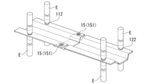
- FIG. 2 is a perspective view of a first simulation model (Comparative Example No. 1).
- FIG. 2 is a perspective view of a first simulation model (Comparative Example No. 1).
- FIG. 2 is a side view of a first simulation model (Comparative Example No. 1).
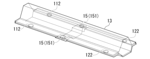
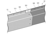
- FIG. 13 is a perspective view of a second simulation model (Invention Example No. 2).
- FIG. 13 is a perspective view of a second simulation model (Invention Example No. 2).
- FIG. 13 is a side view of the second simulation model (Invention Example No. 2).
- FIG. 13 is a perspective view of a third simulation model (Invention Example No. 3).
- FIG. 13 is a perspective view of a third simulation model (Invention Example No. 3).
- FIG. 13 is a side view of the third simulation model (Invention Example No. 3).
- FIG. 2 is a schematic diagram for explaining three-point bending conditions. 13 is a graph showing the results of a simulation.
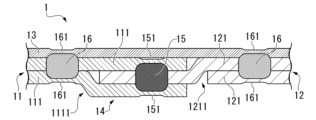
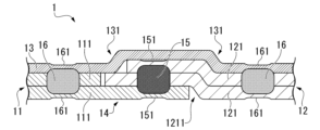
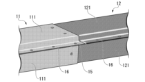
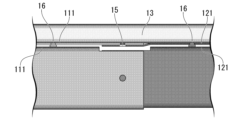
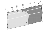
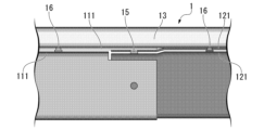
- a spot welding structure 1 is applied to, for example, a flange portion of a frame member of an automobile body, and as shown in FIG. 1 etc., includes a first lap joint 11 having two or more metal plates, a second lap joint 12 having two or more metal plates, a lap portion 14 in which one or more ends of the metal plates 111 of the first lap joint and one or more ends of the metal plates 121 of the second lap joint are overlapped, a main nugget 15 that joins the first lap joint 11 and the second lap joint 12 at the lap portion 14, and
- the joint comprises a metal plate-like member 13 overlapped on the lap joint 11, the second lap joint 12, and the wrap portion 14, and a plurality of secondary nuggets 16 that join the plate-like member 13 and the first lap joint 11, and the plate-like member 13 and the second lap joint 12, the number of metal plates joined by the main nugget 15 is three, the impression 151 of the main nugget 15 is only provided on the metal plates included in
- the spot welding structure 1 is a welded structure obtained by further spot welding the ends of the two lap joints.
- the two lap joints are referred to as a first lap joint 11 and a second lap joint 12.
- Any side of the two lap joints can be regarded as the first lap joint 11.
- the B-pillar may be regarded as the first lap joint 11, or the side sill may be regarded as the first lap joint 11.
- the lap joint on the left side of the paper is regarded as the first lap joint 11
- the lap joint on the right side of the paper is regarded as the second lap joint 12.
- the term "lap joint” means both the first lap joint 11 and the second lap joint 12 unless otherwise specified.
- a lap joint is a joint in which parts are placed approximately parallel and overlap each other.
- the parts of the lap joint are metal plates.
- a lap joint is a joint obtained by overlapping and welding multiple metal plates.
- An example of a lap joint is a frame member of an automobile body to which an inner frame structure is applied.
- the metal plate can have any shape suitable for spot welding.
- the term "metal plate” is a concept that includes not only flat metal plates, but also flat regions of metal components having a three-dimensional shape.
- the flange portion of a hat-shaped component is also considered to be a metal plate.
- the plate-shaped components described below are also a concept that includes flat regions of metal components having a three-dimensional shape.
- the number of metal plates in the lap joint is two.
- the number of metal plates in the lap joint can be any value equal to or greater than three.
- the main nugget 15 joins three metal plates. In FIG. 1, the main nugget 15 joins one metal plate 111 of the first lap joint 11 and two metal plates 121 of the second lap joint 12. Alternatively, the main nugget 15 may join two metal plates of the first lap joint 11 and one metal plate of the second lap joint 12.
- an indentation is formed so as to overlap the nugget.
- the indentation is a depression on the surface of the base material caused by the electrode tip as a result of spot welding.
- the indentation 151 of the main nugget 15 is only provided on the metal plate included in the first lap joint 11 or the second lap joint 12.
- the indentation 151 of the main nugget is not provided on the plate-like member 13 described below.
- the plate-like member 13 is outside the main nugget 15 described above.
- the main nugget 15 described above does not have the function of joining the plate-like member 13 to the first lap joint 11 or the second lap joint 12.
- the main nugget 15 is formed by spot welding (primary spot welding, described later) in which only the metal plate 111 of the first lap joint 11 and the metal plate 121 of the second lap joint 12 are to be welded. Therefore, the impression 151 of the main nugget 15 is not provided on the plate-like member 13.
- the secondary nugget 16 is provided outside the lap portion 14. Therefore, the secondary nugget 16 does not join the first lap joint 11 and the second lap joint 12.
- the secondary nugget impression 161 is also necessarily provided outside the lap portion 14.
- the main nugget 15 that joins the first lap joint 11 and the second lap joint 12 joins three skeletal members (metal plates).
- the plate-shaped member 13 is outside the main nugget 15.
- the main nugget 15 is separated from the plate-shaped member 13. Therefore, there are three skeletal members (metal plates) that are directly involved in joining the first lap joint 11 and the second lap joint 12. As a result, the load transmission efficiency is dramatically improved in the spot welding structure 1 according to this embodiment.
- the spot welding structure 1 when manufacturing the spot welding structure 1 according to this embodiment, it is not necessary to grow the main nugget 15 up to the plate-shaped member 13. Therefore, in the spot welding (primary spot welding) for forming the main nugget 15, it is not necessary to make the welding current excessively large. This makes it possible to suppress the occurrence of expulsion and blowholes, and further increase the joint strength of the main nugget 15.
- a secondary nugget 16 that joins the plate-shaped member 13 to another member is provided outside the lap portion 14. This makes it possible to suppress poor joining of the plate-shaped member 13.
- the total thickness of the metal plate outside the wrap portion 14 is smaller than the total thickness of the metal plate in the wrap portion 14. Therefore, the sheet thickness ratio outside the wrap portion 14 is smaller than the sheet thickness ratio in the wrap portion 14.
- the spot welding structure 1 according to this embodiment When the spot welding structure 1 according to this embodiment is applied to the inner frame structure of an automobile body, the plate-like member 13 becomes the outer plate member of the vehicle body, and the first lap joint 11 and the second lap joint 12 become the skeletal members of the vehicle body.
- the spot welding structure 1 according to this embodiment can suppress poor joining of the outer plate members and increase the load transmission efficiency between the skeletal members.
- the distance d between the center of the secondary nugget 16 joining the plate-like member 13 and the first lap joint 11 and the center of the secondary nugget 16 joining the plate-like member 13 and the second lap joint 12 is 200 mm or less. This further improves the load transmission efficiency of the spot welding structure 1.
- the distance d may be 190 mm or less, 180 mm or less, 160 mm or less, or 140 mm or less.
- the center-to-center distance of the secondary nuggets 16 is determined by measuring the center-to-center distance of the indentations 161 of the secondary nuggets 16.
- the distance d between the center of the secondary nugget 16 joining the plate-like member 13 and the first lap joint 11 and the center of the secondary nugget 16 joining the plate-like member 13 and the second lap joint 12 means the minimum center-to-center distance of the secondary nuggets 16.
- the lap portion 14 is preferably a butt joint.
- a butt joint is understood to be a type of joint in which one member and/or part of a lap joint is stepped so that the base material surface is substantially flush (JIS Z 3001-1:2018).
- at least one of the metal plates 111 of the first lap joint 11 and the metal plate 121 of the second lap joint 12 has a butt joint in the lap portion 14, and two of the three metal plates joined by the main nugget 15 are preferably arranged on substantially the same plane outside the lap portion 14.
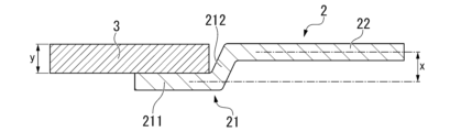
- a metal plate 2 having an edge processing portion 21 is stacked on a metal plate 3 without an edge processing portion.
- the edge processing portion 21 is formed, for example, by bending the metal plate 2 into a stepped shape.
- the edge processing portion 21 has a tip portion 211 and a connection portion 212.
- the portion of the metal plate 2 having the edge processing portion 21, excluding the edge processing portion 21, is referred to as a main body portion 22.
- the tip 211 of the cut section 21 is approximately parallel to the main body 22 of the metal plate 2, but is not on the same plane as the main body 22 of the metal plate 2.
- the plane that contains the tip 211 is separated a predetermined distance x from the plane that contains the main body 22. It is preferable that the predetermined distance x is approximately the same as the thickness y of the metal plate 3 that is overlapped with the cut section 21.
- the tip 211 constitutes the lap portion 14.
- the tip 211 has a width that is at least sufficient to allow spot welding.
- connection part 212 of the edge processing part 21 connects the tip part 211 of the edge processing part 21 and the main body part 22 of the metal plate 2.
- the connection part 212 forms a predetermined angle with the tip part 211 of the edge processing part 21 and the main body part 22 of the metal plate 2.
- the connection part 212 separates the plane containing the tip part 211 of the edge processing part 21 by a predetermined distance x from the plane containing the main body part 22 of the metal plate 2.
- the connection part 212 may be flat or curved.
- metal plate 3 is disposed in the space between a plane including tip 211 of seam processing portion 21 and a plane including main body 22 of metal plate 2.
- One surface of metal plate 2 having seam processing portion 21 is disposed substantially flush with one surface of metal plate 3 that overlaps seam processing portion 21.
- the ends of the two metal plates 121 of the second lap joint 12 are provided with a seam 1211.
- the two metal plates 111 of the first lap joint 11 do not have a seam.
- the metal plate 111 on the upper side of the first lap joint 11 is disposed between the edge processing portion 1211 of the metal plate 121 on the upper side of the second lap joint 12 and the plate-shaped member 13.
- the edge processing portion 1211 of the metal plate 121 on the upper side of the second lap joint 12 is disposed between the edge processing portion 1211 of the metal plate 121 on the lower side of the second lap joint 12 and the metal plate 111 on the upper side of the first lap joint 11.
- the metal plate 111 of the first lap joint 11 and the metal plate 121 of the second lap joint 12 are disposed on approximately the same plane.
- the metal plate 111 on the upper side of the page of the first lap joint 11 (2) the edge processing portion 1211 of the metal plate 121 on the upper side of the page of the second lap joint 12, and (3) the edge processing portion 1211 of the metal plate 121 on the lower side of the page of the second lap joint 12 are overlapped in this order.
- the main nugget 15 joins the three metal plates of the lap portion 14.
- the metal plate 111 on the lower side of the page of the first lap joint 11 is excluded from the lap portion 14.
- a seam 1211 is provided only on the end of the metal plate 121 on the lower side of the paper of the second lap joint 12.
- the two metal plates 111 of the first lap joint 11 and the metal plate 121 on the upper side of the paper of the second lap joint 12 do not have a seam.
- the two metal plates 111 of the first lap joint 11 are arranged between the cutout portion 1211 of the metal plate 121 on the lower side of the paper surface of the second lap joint 12 and the plate-shaped member 13.
- the metal plate 111 of the first lap joint 11 and the metal plate 121 of the second lap joint 12 are arranged on approximately the same plane.
- the metal plate 111 on the upper side of the first lap joint 11 (2) the metal plate 111 on the lower side of the first lap joint 11, and (3) the edge processing portion 1211 of the metal plate 121 on the lower side of the second lap joint 12 are overlapped in this order.
- the main nugget 15 joins the three metal plates of the lap portion 14.
- the metal plate 121 on the upper side of the second lap joint 12 is excluded from the lap portion 14.
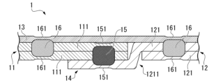
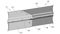
- a seam processing portion 1111 is provided at the end of the metal plate 111 on the lower side of the page of the first lap joint 11, and a seam processing portion 1211 is provided at the end of the metal plate 121 on the upper side of the page of the second lap joint 12.
- the metal plate 111 on the upper side of the page of the first lap joint 11 and the metal plate 121 on the lower side of the page of the second lap joint 12 do not have a seam processing portion.
- the metal plate 111 on the upper side of the first lap joint 11 is disposed between the edge processing portion 1211 of the metal plate 121 on the upper side of the second lap joint 12 and the plate-shaped member 13.
- the edge processing portion 1211 of the metal plate 121 on the upper side of the second lap joint 12 is disposed between the metal plate 111 on the upper side of the first lap joint 11 and the edge processing portion 1111 of the metal plate 111 on the lower side of the first lap joint 11.
- the metal plate 111 of the first lap joint 11 and the metal plate 121 of the second lap joint 12 are disposed on approximately the same plane.
- the metal plate 111 on the upper side of the page of the first lap joint 11 (2) the edge processing portion 1211 of the metal plate 121 on the upper side of the page of the second lap joint 12, and (3) the edge processing portion 1111 of the metal plate 111 on the lower side of the page of the first lap joint 11 are overlapped in this order.
- the main nugget 15 joins the three metal plates of the lap portion 14.
- the metal plate 121 on the lower side of the page of the second lap joint 12 is excluded from the lap portion 14.
- a seam 1211 is provided only on the end of the metal plate 121 on the upper side of the page of the second lap joint 12.
- the two metal plates 111 of the first lap joint 11 and the metal plate 121 on the lower side of the page of the second lap joint 12 do not have a seam.
- the two metal plates 111 of the first lap joint 11 are arranged between the cutout portion 1211 of the metal plate 121 on the upper side of the page of the second lap joint 12 and the plate-shaped member 13.
- the metal plate 111 of the first lap joint 11 and the metal plate 121 of the second lap joint 12 are arranged on approximately the same plane.
- the metal plate 111 on the upper side of the first lap joint 11 (2) the metal plate 111 on the lower side of the first lap joint 11, and (3) the edge processing portion 1211 of the metal plate 121 on the upper side of the second lap joint 12 are overlapped in this order.
- the main nugget 15 joins the three metal plates of the lap portion 14.
- the metal plate 121 on the lower side of the second lap joint 12 is excluded from the lap portion 14.
- the plate-like member 13 may have a seam processing portion.
- the two metal plates 121 of the second lap joint 12 are provided with a seam processing portion 1211. Furthermore, the plate-like member 13 is also provided with a seam processing portion 131.
- the two metal plates 111 of the first lap joint 11 do not have a seam processing portion.
- the edge processing portion 1211 of the metal plate 121 on the lower side of the paper of the second lap joint 12 is disposed between the edge processing portion 1211 of the metal plate 121 on the upper side of the paper of the second lap joint 12 and the metal plate 111 on the lower side of the paper of the first lap joint 11.
- the metal plate 111 of the first lap joint 11 and the metal plate 121 of the second lap joint 12 are disposed on approximately the same plane.
- the edge processing portion 1211 of the metal plate 121 on the upper side of the paper of the second lap joint 12 forms a convex portion facing the upper side of the paper.
- this convex portion is stored in the edge processing portion 131 of the plate-shaped member 13. Therefore, no large gap is generated between the plate-shaped member 13 and the main body portion 1112 of the metal plate 111 of the first lap joint 11 and/or the main body portion 1212 of the metal plate 121 of the second lap joint 12.
- a gap may be present between the plate-shaped member 13 and the first lap joint 11 and/or the second lap joint 12.
- the edged portion 1211 of the metal plate 121 on the upper side of the paper of the second lap joint 12 (2) the edged portion 1211 of the metal plate 121 on the lower side of the paper of the second lap joint 12, and (3) the metal plate 111 on the lower side of the paper of the first lap joint 11 are overlapped in this order.
- the main nugget 15 joins the three metal plates of the lap portion 14.
- the metal plate 111 on the upper side of the paper of the first lap joint 11 is excluded from the lap portion 14.
- Multiple main nuggets 15 may be provided in the lap portion 14.
- the two metal plates 121 of the second lap joint 12 are provided with a seam 1211.
- the two metal plates 111 of the first lap joint 11 do not have a seam.
- the metal plate 111 on the upper side of the page of the first lap joint 11 is disposed between the seam processing portion 1211 of the two metal plates 121 of the second lap joint 12 and the plate-like member 13.
- the metal plate 111 of the first lap joint 11 and the metal plate 121 of the second lap joint 12 are disposed on approximately the same plane.
- the metal plate 111 of the first lap joint 11 and the metal plate 121 of the second lap joint 12 are arranged on approximately the same plane, thereby further improving the load transmission efficiency.
- the number of joint interfaces between the first lap joint 11 and the second lap joint 12 may be two or more. By making the number of joint interfaces between the first lap joint 11 and the second lap joint 12 two or more, the rigidity of the spot welding structure 1 is further improved.
- the lap portion 14 is also divided into two.
- the metal plate 111 on the upper side of the paper of the first lap joint 11 11, the edge processing portion 1211 of the metal plate 121 on the upper side of the paper of the second lap joint 12, and the edge processing portion 1111 of the metal plate 111 on the lower side of the paper of the first lap joint 11 are stacked in this order.
- a main nugget 15 is formed to join the three metal plates.
- the edge processing portion 1211 of the metal plate 121 on the upper side of the paper of the second lap joint 12 forms a convex portion in the lap portion 14.
- the convex portion is housed inside the edge processing portion 131 provided on the plate-shaped member 13.
- the lap portion 14 is also divided into two.
- the metal plate 111 on the upper side of the paper of the first lap joint 11 11, the edge processing portion 1211 of the metal plate 121 on the upper side of the paper of the second lap joint 12, and the edge processing portion 1111 of the metal plate 111 on the lower side of the paper of the first lap joint 11 are overlapped in order.
- the metal plate 111 on the upper side of the paper of the first lap joint 11, the edge processing portion 1211 of the metal plate 121 on the upper side of the paper of the second lap joint 12, and the edge processing portion 1211 of the metal plate 121 on the lower side of the paper of the second lap joint 12 are overlapped in order.
- a main nugget 15 is formed to join the three metal plates.
- the wrap portion 14 is divided into two, and in each of the two wrap portions 14, a main nugget 15 is formed that joins the three metal plates, forming two joint structures. This further improves the load transmission efficiency. Also, two or more main nuggets 15 may be formed in each wrap portion 14. This further improves the load transmission efficiency.
- the spot welding structure 1 further includes an adhesive 17.
- the adhesive 17 is disposed between the plate-shaped member 13 and one or both of the first lap joint 11 and the second lap joint 12, for example, as shown in FIG. 6. This further increases the joint strength between the plate-shaped member 13 and other members.
- the adhesive 17 may also be provided between the metal plate 111 of the first lap joint 11 and the metal plate 121 of the second lap joint 12. This further increases the joint strength of the two lap joints and also increases the load transmission efficiency.
- the adhesive 17 may be disposed between the multiple metal plates 111 included in the first lap joint 11, or may be disposed between the multiple metal plates 121 included in the second lap joint 12. This further increases the joint strength of the first lap joint 11 and/or the second lap joint 12.
- the type of adhesive 17 is not particularly limited. Examples of the adhesive 17 include epoxy-based, rubber-based, silicone-based, or a mixture of these adhesives.
- the adhesive may be of the heat-curing or reaction-curing type, but when applied to automobile bodies, the adhesive is preferably of the heat-curing type that cures during the heat treatment step (140° C. to 190° C.) of electrodeposition coating.
- the spot welding structure 1 may further include an additional nugget 18 in the lap portion 14.
- the additional nugget 18 joins two or more of the metal plates and the plate-like members 13 included in the lap portion 14.
- the additional nugget 18 is similar to the main nugget 15 in that it is provided in the lap portion 14. However, unlike the main nugget 15, one of the two indentations of the additional nugget 18 is provided in the plate-like member 13.
- the additional nugget 18 is obtained by spot welding to the lap portion 14 in a state where the plate-like member 13 is further overlapped on the lap portion 14.
- the lap portion 14 When a plate-like member 13 is further layered on the lap portion 14, the lap portion 14 will contain four or more metal plates. In spot welding of such plate assemblies, expulsion is usually likely to occur. However, the plate gaps in the lap portion 14 are removed when the main nugget 15 and the secondary nugget 16 are formed. Therefore, expulsion caused by the plate gaps is suppressed when the additional nugget 18 is formed.
- the additional nugget 18 only needs to join at least two of the metal plates and the plate-like member 13 included in the lap portion 14.
- the additional nugget 18 does not need to grow to the plate-like member 13. That is, the additional nugget 18 does not need to join the plate-like member 13 to another member.
- the additional nugget 18 may press the plate-like member 13 to another member. Even if the additional nugget 18 is outside the plate-like member 13, the additional nugget 18 can have the effect of improving the joint strength and load transmission efficiency of the two lap joints.
- the additional nugget 18 may be provided apart from the main nugget 15.
- the additional nugget 18 and the main nugget 15 may be partially fused. An example of a cross section in which the additional nugget 18 and the main nugget 15 are partially fused is shown in FIG. 15.
- the spot welded structure 1 does not have to have the additional nugget 18 in the lap portion 14. That is, the plate-like member may be separated from the first lap joint and the second lap joint over the entire lap portion. By omitting the additional nugget 18, the manufacturing cost of the spot welded structure 1 can be reduced, and the time required to manufacture the spot welded structure 1 can be shortened.
- the first lap joint may have a joint outside the lap portion that joins only the metal plates of the first lap joint.
- the second lap joint may have a joint outside the lap portion that joins only the metal plates of the second lap joint.
- the joints are, for example, the nugget 112 of the first lap joint 11 and the nugget 122 of the second lap joint 12 shown in FIG. 1.
- the nugget 112 of the first lap joint 11 joins the metal plates 111 of the first lap joint 11, but does not join the first lap joint 11 to another member.
- the nugget 122 of the second lap joint 12 joins the metal plates 121 of the second lap joint 12, but does not join the second lap joint 12 to another member.
- the metal plates included in the lap joint may be joined by arc welded metal, seam welded metal, laser welded metal, or a combination of these.
- a first manufacturing method of a spot welded structure 1 includes the following steps, as shown in FIGS. 8A to 8E: (S1) preparing a first lap joint 11 having two or more metal plates and a second lap joint 12 having two or more metal plates; (S2) a step of overlapping one or more ends of the metal plates 111 of the first lap joint and one or more ends of the metal plates 121 of the second lap joint to form a lap portion 14; (S3) a step of primarily spot welding the first lap joint 11 and the second lap joint 12 at the lap portion 14 to form a main nugget 15; (S4) a process of overlapping a metal plate-like member 13 on the lap portion 14 on which the first lap joint 11, the second lap joint 12, and the main nugget 15 are formed; (S5) a step of secondary spot welding the plate-like member 13 and the first lap joint 11, and the plate-like member 13 and the second lap joint 12 to form a plurality of secondary nugget
- a first lap joint 11 having two or more metal plates and a second lap joint 12 having two or more metal plates are prepared.
- the process of preparing the lap joint may be a process of manufacturing the first lap joint 11 having two or more metal plates and the second lap joint 12 having two or more metal plates.
- the process of manufacturing the lap joint is, for example, a spot welding process shown in FIG. 8A.
- the process of manufacturing the lap joint may be, for example, a laser welding process, a seam welding process, a lap arc welding process, or the like.
- a lap joint manufactured by another person may be used as the first lap joint 11 and the second lap joint 12.
- An example of the first lap joint and the second lap joint is a frame part of an automobile, and an example of the plate-like member 13 is an outer plate part of an automobile.
- first lap joint 11 and the second lap joint 12 it is preferable to shape these ends. For example, it is preferable to have only one of the two or more metal plates in the lap joint protrude. By machining the end of the lap joint or by positioning the end of the metal plate before manufacturing the lap joint, it is possible to have only one of the two or more metal plates in the lap joint protrude. It is also preferable to provide a seam processing portion in one or more of the two or more metal plates. The seam processing portion can be formed by machining the end of the metal plate before or after manufacturing the lap joint.
- first lap joint 11 illustrated in FIG. 8A only one of the two or more metal plates 111 protrudes.
- second lap joint 12 illustrated in FIG. 8A only one of the two or more metal plates 121 protrudes, and both of the two metal plates 121 have a seam.
- various aspects such as those illustrated in FIG. 1, FIG. 4A to FIG. 4E, and FIG. 5A to FIG. 5D can be applied to the ends of the first lap joint 11 and the second lap joint 12.
- the two lap joints are aligned so that the ends of the metal plates are inserted into the space formed by the seam processing portion.
- This alignment is also considered to be overlapping the ends of one or more of the metal plates 111 of the first lap joint and the ends of one or more of the metal plates 121 of the second lap joint.
- all of the actions for forming the lap portion 14 are considered to be actions of overlapping the ends of the metal plates.
- the first lap joint 11 and the second lap joint 12 are primarily spot welded at the lap portion 14 to form a main nugget 15.
- an impression 151 of the main nugget is formed in the metal plate disposed on the outermost surface of the lap portion 14 by the primary spot welding.
- the number of metal plates to be primarily spot welded is three. Therefore, it is preferable to use the area in the lap portion 14 where three metal plates are overlapped as the welding point for the primary spot welding.
- the number of times primary spot welding may be one, or two or more.
- the plate-like member 13 and the first lap joint 11, and the plate-like member 13 and the second lap joint 12 are secondarily spot welded to form a plurality of sub-nuggets 16.
- the welding points of the secondary spot welding are outside the lap portion 14.
- the secondary spot welding is performed at least once on the plate-like member 13 and the first lap joint 11, and at least once on the plate-like member 13 and the second lap joint 12.
- the total number of secondary spot welding may be three or more times.
- the first manufacturing method of the spot welded structure 1 according to the present embodiment three metal plates are overlapped at the joints of the two lap joints. Therefore, the first manufacturing method according to the present embodiment can firmly join the two lap joints. In addition, the spot welded structure 1 obtained by the first manufacturing method according to the present embodiment has excellent load transmission efficiency.
- the welding point in the secondary spot welding for joining the plate-shaped member 13 to the other member is outside the lap portion 14. Therefore, in the first manufacturing method according to this embodiment, the total thickness of the plate assembly in the secondary spot welding is also reduced. This also suppresses the occurrence of expulsion in the secondary spot welding. In addition, poor joining between the plate-shaped member 13 and the other member is avoided.
- FIGS. 9A to 9F A second manufacturing method of the spot welded structure 1 according to another embodiment of the present invention is as shown in FIGS. 9A to 9F .
- (s1) preparing a plate set in which two of the metal plates that are components of a first lap joint are overlapped at their ends;
- (s2) a step of overlapping an end of one of the metal plates that is a component of the second lap joint on an end of the plate assembly to form a lap portion;
- (s4) a step of overlapping and spot welding one metal plate of the second lap joint provided with the main nugget and the remaining metal plate of the second lap joint outside the lap portion to form a second lap joint;
- (s5) placing a metal plate-like member on the lap portion on which the first lap joint, the second lap joint, and
- the second manufacturing method differs from the first manufacturing method in that the first lap joint and the second lap joint are not formed before the primary spot welding is performed.
- the second manufacturing method is very similar to the first manufacturing method.
- the first manufacturing method and the second manufacturing method are identical in terms of the process of stacking the plate-like members and the subsequent processes. Therefore, in the following description of the second manufacturing method, matters that overlap with the first manufacturing method may be omitted. Suitable aspects of the first manufacturing method can be applied to the second manufacturing method.
- a plate set is prepared by overlapping two metal plates at their ends. These two metal plates are parts of a first lap joint. However, at this point, the metal plates of the first lap joint are not joined together.
- two of the metal plates that are components of the first lap joint and one of the metal plates that are components of the second lap joint are primarily spot welded at the lap portion. This brings the number of metal plates that are primarily spot welded to three.
- a main nugget is formed by the primary spot welding.
- a first lap joint is formed by the primary spot welding, which includes two metal plates and a main nugget that joins the two metal plates.
- one metal plate of the second lap joint in which the main nugget is provided is overlapped with the remaining metal plate of the second lap joint outside the lap portion, and the overlapped portion is spot welded to form the second lap joint.
- the second lap joint has only two metal plates.
- a second lap joint having three or more metal plates can be manufactured by overlapping and spot welding one metal plate of the second lap joint in which the main nugget is provided with two or more metal plates.
- additional spot welding may be performed on the first lap joint as shown in FIG. 9D.
- an additional metal plate may be added, so that the number of metal plates in the first lap joint is three or more.
- a metal plate-shaped member is placed on the lap portion where the first lap joint, the second lap joint, and the main nugget are formed. Furthermore, as shown in Fig. 9F, the plate-shaped member and the first lap joint, and the plate-shaped member and the second lap joint are secondarily spot welded to form a plurality of sub-nuggets. The welding points in the secondary spot welding are outside the lap portion. In the second manufacturing method, the process of welding the plate-shaped member to another member by placing it on top of it is substantially the same as in the first manufacturing method.
- the second manufacturing method of the spot welding structure 1 according to the present embodiment As in the first manufacturing method, in the second manufacturing method of the spot welding structure 1 according to the present embodiment, three metal plates are overlapped at the joint of the two lap joints. As in the first manufacturing method, in the second manufacturing method according to the present embodiment, the welding point in the secondary spot welding for joining the plate-shaped member 13 to another member is outside the lap portion 14. Therefore, according to the second manufacturing method according to the present embodiment, a spot welding structure with excellent load transmission efficiency is obtained. Furthermore, the second manufacturing method can suppress the occurrence of splashing. In addition, according to the second manufacturing method, poor joining between the plate-shaped member 13 and another member is avoided.
- the distance between the center of the welding point in the secondary spot welding of the plate-like member 13 and the first lap joint 11 and the center of the welding point in the secondary spot welding of the plate-like member 13 and the second lap joint 12 is 200 mm or less. This makes it possible to set the distance d between the center of the secondary nugget 16 joining the plate-like member 13 and the first lap joint 11 and the center of the secondary nugget 16 joining the plate-like member 13 and the second lap joint 12 to 200 mm or less. This further improves the load transmission efficiency of the spot welding structure 1.
- the distance between the centers of the welding points may be 190 mm or less, 180 mm or less, 160 mm or less, or 140 mm or less.
- the distance between the center of the welding point in the secondary spot welding of the plate-like member 13 and the first lap joint 11 and the center of the welding point in the secondary spot welding of the plate-like member 13 and the second lap joint 12 means the minimum center-to-center distance of the welding points.
- a seam processing portion may be provided at the end of one or more of the metal plates 111 of the first lap joint 11 and the metal plates 121 of the second lap joint 12, and when forming the lap portion 14, two of the three metal plates joined by the main nugget 15 may be arranged on approximately the same plane outside the lap portion 14.
- the load transmission efficiency is further improved.
- a specific example of the seam structure is the same as the preferred aspect of the spot welding structure 1 according to this embodiment, as exemplified in Figures 1 and 4A to 4E.
- the lap portion 14 may be subjected to primary spot welding a plurality of times.
- the plate combination may be the same in the plurality of primary spot weldings.
- the plate combination may be different in the plurality of primary spot weldings.
- a lap portion 14 in which two metal plates 111 of the first lap joint 11 and one metal plate 121 of the second lap joint 12 are overlapped, and a lap portion 14 in which one metal plate 111 of the first lap joint 11 and two metal plates 121 of the second lap joint 12 are overlapped may be formed, and primary spot welding may be performed on each of the plurality of lap portions 14.
- primary spot welding may also be performed multiple times on the lap portion 14.
- the plate combinations may be the same in the multiple primary spot weldings.
- the plate combinations may be different in the multiple primary spot weldings.
- the primary spot welding in order to perform multiple primary spot welding on different plate pairs, the primary spot welding must be performed in two stages. This is because only one of the metal plates of the second lap joint is included in the lap portion during the first primary spot welding. Therefore, during the first primary spot welding, a main nugget is formed that joins the two metal plates 111 of the first lap joint 11 and the one metal plate 121 of the second lap joint 12.
- the other metal plate 121 of the second lap joint 12 is overlapped on the one metal plate 121 of the second lap joint 12 to form an additional lap portion in which the one metal plate 111 of the first lap joint 11 and the two metal plates 121 of the second lap joint 12 are overlapped.
- the additional lap portion is subjected to primary spot welding to form a main nugget that joins the one metal plate 111 of the first lap joint 11 and the two metal plates 121 of the second lap joint 12.
- Either manufacturing method can be used to manufacture a spot welded structure 1 having a main nugget 15 that joins the two metal plates 111 of the first lap joint 11 to the one metal plate 121 of the second lap joint 12, and a main nugget 15 that joins the one metal plate 111 of the first lap joint 11 to the two metal plates 121 of the second lap joint 12. This further improves the load transmission efficiency of the spot welded structure 1.
- the lap portion 14 when performing multiple primary spot welding can be, for example, in the form shown in Figures 5A to 5D.
- the secondary spot welding may be a method of spot welding after applying a weld bond, i.e., an adhesive 17 to the joint interface in advance.
- the manufacturing method of the spot welding structure 1 may further include a step of applying an adhesive 17 between the plate-shaped member 13 and one or both of the first lap joint 11 and the second lap joint 12 after the primary spot welding and before overlapping the plate-shaped member 13 on the lap portion 14 on which the first lap joint 11, the second lap joint 12, and the main nugget 15 are formed. This makes it possible to manufacture the spot welding structure 1 in which the adhesive 17 is disposed between the plate-shaped member 13 and one or both of the first lap joint 11 and the second lap joint 12 as illustrated in FIG. 6 . Then, the joining strength between the plate-shaped member 13 and another member is further increased.
- the manufacturing method of the spot welded structure 1 may further include a step of performing additional spot welding on the lap portion 14 and the plate-like member 13 after the secondary spot welding. This makes it possible to manufacture a spot welded structure 1 that further has an additional nugget 18 in the lap portion 14 as shown in FIG. 7 .
- the lap portion 14 When a plate-shaped member 13 is further layered on the lap portion 14, the lap portion 14 will contain four or more metal plates.
- the metal plates referred to here include the metal plates that make up the plate-shaped member 13. In spot welding of such a plate assembly, expulsion is usually likely to occur. However, the plate gaps in the lap portion 14 are removed when the main nugget 15 and the secondary nugget 16 are formed. Therefore, expulsion caused by the plate gaps is suppressed during additional spot welding.
- the additional spot welding only needs to join at least two of the metal plates and the plate-like member 13 included in the lap portion 14.
- the additional spot welding does not need to grow the additional nugget 18 to the plate-like member 13. That is, the additional nugget 18 does not need to join the plate-like member 13 to another member.
- the additional nugget 18 may press the plate-like member 13 to another member. Even if the additional nugget 18 is outside the plate-like member 13, the additional nugget 18 can have the effect of improving the joint strength and load transmission efficiency of the two lap joints.
- the welding point of the additional spot welding may be separated from the welding point of the primary spot welding, or may overlap with the welding point of the primary spot welding.
- the manufacturing method of the spot welded structure 1 does not have to include a step of performing additional spot welding.
- all spot welding to the plate-like member may be performed outside the lap portion.
- the plate thickness ratio of the lap portion 14 is a value obtained by dividing the total thickness of the three metal plates and the plate-shaped member 13 at the location where the main nugget 15 is provided by the thickness of the plate-shaped member 13.
- the plate thickness ratio of the lap portion 14 is preferably within a range of 6.0 to 11.0.
- the larger the plate thickness ratio the more difficult it is to join the plate-shaped member 13.
- the spot welding structure 1 according to this embodiment and the manufacturing method thereof the plate-shaped member 13 is firmly joined outside the lap portion 14. Therefore, it is not essential that the plate-shaped member 13 is welded at the lap portion 14. Even if the plate thickness ratio of the lap portion 14 is large, poor joining of the plate-shaped member 13 does not become a problem.
- the thickness ratio of the secondary nugget forming portion is the total thickness of the multiple metal plates and the plate-like member 13 at the location where the secondary nugget 16 is provided, divided by the thickness of the plate-like member 13.
- the thickness ratio of the secondary nugget forming portion is preferably within the range of 3.0 to 6.0. More preferably, the upper limit is 5.5. The smaller the thickness ratio of the secondary nugget forming portion, the more likely it is that poor joining of the plate-like member 13 will be avoided.
- the plate thickness ratio is determined by measuring the thickness of the metal plate and plate-like member 13 in a cross section passing through the center of the indentation and perpendicular to the surface of the plate-like member 13. If the thickness of the metal plate and plate-like member 13 has been reduced by the indentation, the thickness measured at a location not affected by the indentation is used to calculate the plate thickness ratio.
- the type of the metal plate of the lap joint is not particularly limited.
- the type of the metal plate constituting the plate-shaped member 13 is also not particularly limited.
- any material that can be spot welded can be used as the metal plate of the lap joint and the metal plate constituting the plate-shaped member 13.
- a suitable material can be adopted depending on the application of the spot welding structure 1.
- the metal plate include a steel plate, an aluminum plate, and a stainless steel plate.
- a suitable example of a metal plate is a steel plate.
- one or more of the metal plates be high-strength steel plates.
- the thickness of the metal plates can be reduced while ensuring the strength of the spot welded structure 1 by using high-strength steel plates for one or more of the metal plates. By reducing the thickness of the metal plates, the spot welded structure 1 can be made lighter.
- the plate-shaped member 13 is mild steel and at least one of the metal plates included in the lap joint is a high-strength steel plate.
- the Vickers hardness of the plate-shaped member 13 is 150 HV or less, 140 HV or less, 130 HV or less, or 120 HV or less.
- the tensile strength of the plate-shaped member 13 is 440 MPa or less, 400 MPa or less, or 370 MPa or less.
- the hardness of at least one of the metal plates included in the lap joint is 300 HV or more, 380 HV or more, or 440 HV or more.
- the tensile strength of at least one of the metal plates included in the lap joint is 980 MPa or more, 1200 MPa or more, or 1350 MPa or more.
- the plate-shaped member 13 can be disposed on the outermost surface of the spot welding structure 1, and is therefore suitable, for example, for use as an exterior member of an automobile. By making the plate-shaped member 13 out of thin mild steel, the formability of the plate-shaped member 13 can be improved, and the aesthetic appearance of the automobile can be improved.
- the metal plates included in the lap joint are suitable for automobile frame parts, for example. By making one or more of the metal plates included in the lap joint out of high-strength steel plate, the collision safety of the automobile can be improved.
- the plate-shaped member 13 and the metal plate may have a surface treatment layer.
- the surface treatment layer may be, for example, a chemical conversion layer, a plating layer, etc.
- the configuration of the chemical conversion layer and the plating layer may be suitable for the components of the underlying metal plate.
- the plating layer is preferably, for example, a zinc-based plating layer, an aluminum-based plating layer, etc.
- the zinc-based plating layer is a plating layer having a Zn content of 30 mass% or more.
- Examples of the zinc-based plating layer include a hot-dip galvanized layer, an alloyed hot-dip galvanized layer, an electrogalvanized layer, a zinc-aluminum plating layer, a zinc-aluminum-magnesium plating layer, and a hot-stamped hot-dip galvanized layer.
- the aluminum-based plating layer is a plating layer having an Al content of 20 mass% or more.
- An example of a steel plate having an aluminum-based plating layer is an aluminum-silicon plated steel plate that has been hot-stamped.
- a layer of Al oxide, Ti oxide, or zinc oxide may be provided on the surface of the aluminum plating after hot stamping.
- the thickness of the metal plates of the lap joint there are no particular limitations on the thickness of the metal plates of the lap joint and the thickness of the plate-like member 13.
- the thickness of the plate-like member 13 is preferably 0.5 to 1.1 mm.
- the thickness of the metal plates of the lap joint is preferably 0.9 to 2.6 mm.
- the diameter of the main nugget 15 is not particularly limited, but is preferably, for example, 3 ⁇ t or more, 4 ⁇ t or more, or 5 ⁇ t or more. This increases the joining strength of the main nugget 15. On the other hand, from the viewpoint of suppressing the amount of heat input and further preventing the generation of spatter, it is preferable that the diameter of the main nugget 15 is 9 ⁇ t or less, 8 ⁇ t or less, or 7 ⁇ t or less.
- the numerical range of the diameter of the main nugget 15 can also be applied to the sub nugget 16, the additional nugget 18, the nugget 112 of the first lap joint, and the nugget 122 of the second lap joint.
- the nugget diameter refers to the diameter of the nugget measured along the joint interface in a cross-sectional test of the weld.
- t refers to the plate thickness of the thinner of the two steel plates that make up the joint interface at which the nugget diameter was measured.
- the use of the spot welding structure 1 according to the present embodiment is not particularly limited.
- a suitable use is a joint of a vehicle body to which an inner frame structure is applied.
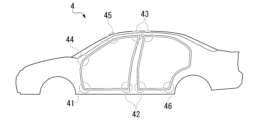
- Fig. 10 shows a joint of a vehicle body 4 of a vehicle.
- the spot welding structure 1 according to the present embodiment to the flanges of joints of the frame parts of the vehicle body, such as a joint 41 between an A-pillar lower and a side sill, a joint 42 between a B-pillar and a side sill, a joint 43 between a B-pillar and a roof rail, a joint 44 between an A-pillar lower and an A-pillar upper, a joint 45 between an A-pillar upper and a roof rail, a joint between a C-pillar and a roof rail, and a joint 46 between a C-pillar and a side sill, an automobile body with high load transmission efficiency can be realized.
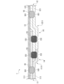
- the first and second plates from the bottom at the left end of the paper are two metal plates constituting the first lap joint.
- the first and second plates from the bottom at the right end of the paper are two metal plates constituting the second lap joint.
- the portion where the second nugget from the right of the paper is provided is a lap portion where an end portion of one of the metal plates of the first lap joint and an end portion of two or more of the metal plates of the second lap joint are overlapped.
- the second nugget from the right of the paper is a main nugget that joins the first lap joint and the second lap joint at the lap portion.
- the top plate on the paper is a plate-like member that is overlapped on the first lap joint, the second lap joint, and the lap portion.
- the first nugget from the right of the paper is a sub-nugget that joins the plate-like member and the first lap joint
- the first nugget from the left is a sub-nugget that joins the plate-like member and the second lap joint.
- the number of metal plates joined by the main nugget is three.
- the main nugget impression is provided only on the metal plates included in the first lap joint or the second lap joint.
- the plate-like member is located outside the main nugget.
- the secondary nugget is located outside the lap portion.
- the location where the second nugget from the left is provided corresponds to the lap portion where an end of one of the metal plates of the first lap joint and an end of one of the metal plates of the second lap joint are overlapped. Since this nugget is provided in the lap portion, it does not correspond to the secondary nugget. On the other hand, since the plate-like member is joined to this nugget, this nugget does not correspond to the main nugget. However, it is of course permissible to add such an additional nugget to the spot welded structure according to this embodiment. Furthermore, as described above, the spot welded joint in Fig.
- the spot welded joint 1 shown in Fig. 11 has all the characteristic features of the spot welded joint according to this embodiment. Therefore, even if the spot welded joint in Fig. 11 has an additional nugget, it is considered to be a spot welded joint according to this embodiment. If the second nugget from the left on the page is ignored, the spot welded joint 1 shown in Fig. 11 has a structure similar to that of Fig. 4A flipped from left to right.
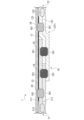
- the spot welded joint 1 shown in FIG. 12 has the same configuration as that shown in FIG.
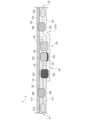
- the spot welded joint 1 shown in FIG. 13 has a configuration similar to that of FIG. 5A, but flipped left and right.
- the spot welded joint 1 shown in FIG. 14 has a configuration similar to that shown in FIG. 5B.
- the spot welded joint 1 shown in FIG. 15 has a configuration similar to that of FIG. 7 but flipped left and right.
- Example The effect of one embodiment of the present disclosure will be explained more specifically by an experiment using a simulation.
- the following condition is merely an example of a condition adopted to confirm the effect of the present disclosure.
- the present disclosure is not limited to this example of a condition.
- Various conditions may be adopted in the present disclosure as long as the purpose is achieved without departing from the gist of the disclosure.
- Models No. 1 to No. 3 are models assuming structural members in which hat-shaped members (metal plates) made of steel plates with thicknesses of 1.2 mm and 1.6 mm and tensile strengths of 1500 MPa are combined and the flanges are spot-welded.
- the outer plate member (plate-shaped member 13) is a steel plate with a thickness of 0.65 mm and tensile strength of 270 MPa.
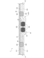
- the spot welding structure of Comparative Example No. 1 is shown in Figures 16A to 16C.
- the spot welding structure of Comparative Example No. 1 is a simulation of a conventional spot welding structure. Note that in Figure 16A, the outer plate member (plate-shaped member 13) is omitted.
- the spot welding structure of Comparative Example No. 1 is a joint for only one of the two steel plates of each of the first lap joint 11 and the second lap joint 12.
- FIG. 1 is a model in which the steel plates of the two frame members (metal plate 111 on the upper side of the paper in Figure 16C and metal plate 121 on the upper side of the paper) and the outer plate member (plate-shaped member 13) are spot-welded together to form a nugget (main nugget 15). Note that the parts that look like holes in Figures 16A and 16B indicate spot welds on the simulation model.
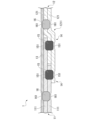
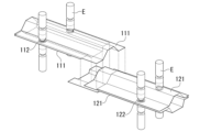
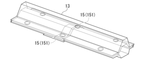
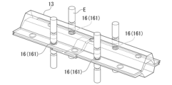
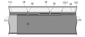
- the spot welding structure 1 of Example No. 2 is shown in Figures 17A to 17C.
- the spot welding structure 1 of Example No. 2 simulates the spot welding structure of the present disclosure.
- the outer plate member plate-shaped member 13
- the main nugget 15 that joins the first lap joint 11 and the second lap joint 12 joins three metal plates.
- the metal plate 111 on the upper side of the paper in Figure 17C, the metal plate 112 on the upper side of the paper, and the metal plate 112 on the lower side of the paper are stacked in this order.
- the spot welding structure of invention example No. 2 has the same configuration as in Figure 1. Note that the parts that look like holes in Figures 17A and 17B indicate spot welds on the simulation model.
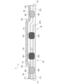
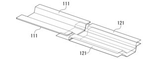
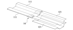
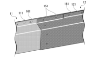
- Spot welding structure 1 of Example No. 3 is shown in Figures 18A to 18C. Spot welding structure 1 of Example No. 3 simulates the spot welding structure of the present disclosure. Note that in Figure 18A, the outer plate member (plate-shaped member 13) is omitted. In the spot welding structure 1 of Example No. 3, the lap portion 14 is divided into two. In the lap portion 14 on the side of the first lap joint 11, the metal plate 111 on the upper side of the first lap joint 11 on the page, the metal plate 111 on the lower side of the first lap joint 11 on the page, and the metal plate 121 on the lower side of the second lap joint 12 on the page are overlapped in that order.
- the metal plate 111 on the upper side of the first lap joint 11, the edged portion 1211 of the metal plate 121 on the upper side of the second lap joint 12, and the edged portion 1211 of the metal plate 121 on the lower side of the second lap joint 12 are overlapped in this order.
- a main nugget 15 is formed to join the three metal plates.
- the plate-shaped member 13 is outside the main nugget 15.
- the main nugget 15 is separated from the plate-shaped member 13. Therefore, in each of the two lap portions 14, the number of metal plates directly involved in the joining of the first lap joint 11 and the second lap joint 12 is three.
- the spot welding structure of the invention example No. 3 has a configuration similar to that of FIG. 5A. Note that the parts that look like holes in Figures 18A and 18B indicate spot welds on the simulation model.
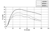
- the simulation model is a long structural member as shown in Fig. 19.
- the basic conditions for the simulation assuming three-point bending are as follows. In Nos. 1 and 2, the impactor was pressed against the position in the longitudinal direction of the structural member where the main nugget 15 was formed, and in No. 3, the impactor was pressed against the midpoint between the two main nuggets 15 in the longitudinal direction of the structural member.
Landscapes
- Engineering & Computer Science (AREA)
- Mechanical Engineering (AREA)
- Chemical & Material Sciences (AREA)
- Combustion & Propulsion (AREA)
- Transportation (AREA)
- Resistance Welding (AREA)
Abstract
Cette structure de soudage par points comprend : un premier joint à recouvrement ; un second joint à recouvrement ; une partie de recouvrement dans laquelle une ou plusieurs extrémités d'une plaque métallique du premier joint à recouvrement et une ou plusieurs extrémités d'une plaque métallique du second joint à recouvrement se chevauchent ; un noyau principal reliant le premier joint à recouvrement et le second joint à recouvrement dans la partie de recouvrement ; un élément en forme de plaque métallique qui est superposé sur le premier joint à recouvrement, le second joint à recouvrement et la partie de recouvrement ; et une pluralité de sous-noyaux reliant l'élément de forme de plaque et le premier joint à recouvrement, et joignant l'élément de forme de plaque et le second joint à recouvrement. Le nombre de plaques métalliques auxquelles le noyau principal est relié est de trois. Une indentation du noyau principal est fournie uniquement à la plaque métallique incluse dans le premier joint à recouvrement ou le second joint à recouvrement. L'élément en forme de plaque est situé à l'extérieur du noyau principal. Les sous-noyaux sont situés à l'extérieur de la partie de recouvrement
Priority Applications (1)
| Application Number | Priority Date | Filing Date | Title |
|---|---|---|---|
| JP2025547446A JP7807719B2 (ja) | 2023-09-19 | 2024-09-19 | スポット溶接構造、及びスポット溶接構造の製造方法 |
Applications Claiming Priority (2)
| Application Number | Priority Date | Filing Date | Title |
|---|---|---|---|
| JP2023150978 | 2023-09-19 | ||
| JP2023-150978 | 2023-09-19 |
Publications (1)
| Publication Number | Publication Date |
|---|---|
| WO2025063243A1 true WO2025063243A1 (fr) | 2025-03-27 |
Family
ID=95073077
Family Applications (1)
| Application Number | Title | Priority Date | Filing Date |
|---|---|---|---|
| PCT/JP2024/033487 Pending WO2025063243A1 (fr) | 2023-09-19 | 2024-09-19 | Structure de soudage par points et procédé de fabrication de structure de soudage par points |
Country Status (2)
| Country | Link |
|---|---|
| JP (1) | JP7807719B2 (fr) |
| WO (1) | WO2025063243A1 (fr) |
Citations (4)
| Publication number | Priority date | Publication date | Assignee | Title |
|---|---|---|---|---|
| US1933484A (en) * | 1932-04-14 | 1933-10-31 | Budd Edward G Mfg Co | Method of welding |
| DE102010063763A1 (de) * | 2010-12-21 | 2012-06-21 | Bayerische Motoren Werke Aktiengesellschaft | Kraftfahrzeugkarosserie mit einem Flansch |
| WO2014007145A1 (fr) * | 2012-07-02 | 2014-01-09 | 本田技研工業株式会社 | Structure soudée pour panneau de carrosserie de véhicule |
| JP2021172139A (ja) * | 2020-04-20 | 2021-11-01 | 本田技研工業株式会社 | 車体側部構造の製造方法 |
-
2024
- 2024-09-19 JP JP2025547446A patent/JP7807719B2/ja active Active
- 2024-09-19 WO PCT/JP2024/033487 patent/WO2025063243A1/fr active Pending
Patent Citations (4)
| Publication number | Priority date | Publication date | Assignee | Title |
|---|---|---|---|---|
| US1933484A (en) * | 1932-04-14 | 1933-10-31 | Budd Edward G Mfg Co | Method of welding |
| DE102010063763A1 (de) * | 2010-12-21 | 2012-06-21 | Bayerische Motoren Werke Aktiengesellschaft | Kraftfahrzeugkarosserie mit einem Flansch |
| WO2014007145A1 (fr) * | 2012-07-02 | 2014-01-09 | 本田技研工業株式会社 | Structure soudée pour panneau de carrosserie de véhicule |
| JP2021172139A (ja) * | 2020-04-20 | 2021-11-01 | 本田技研工業株式会社 | 車体側部構造の製造方法 |
Also Published As
| Publication number | Publication date |
|---|---|
| JPWO2025063243A1 (fr) | 2025-03-27 |
| JP7807719B2 (ja) | 2026-01-28 |
Similar Documents
| Publication | Publication Date | Title |
|---|---|---|
| KR101710851B1 (ko) | 중첩부의 용접 방법 및 겹침 용접 부재 | |
| US12515273B2 (en) | Joint structure, automotive component, and joint structure manufacturing method | |
| US20230294205A1 (en) | Joining structure and method for manufacturing same | |
| US20150314363A1 (en) | Method of forming a vehicle body structure from a pre-welded blank assembly | |
| JPWO2014163203A1 (ja) | 自動車用構造部材、及びその製造方法 | |
| JP2000197969A (ja) | 一体化成形用ブランクおよびその成形方法 | |
| US11383329B2 (en) | Method for producing a workpiece composite, and workpiece composite | |
| JP2020131226A (ja) | 長尺形状のプレス成形部材、及びその製造法 | |
| JP7227063B2 (ja) | 金属構造部材 | |
| JP7807719B2 (ja) | スポット溶接構造、及びスポット溶接構造の製造方法 | |
| JP7234460B2 (ja) | 車体側部構造及び車体側部構造の製造方法 | |
| US11577788B2 (en) | Joining structure of vehicle steel plates and joining method for vehicle steel plates | |
| JP2007283313A (ja) | 異材接合体 | |
| JP7836015B2 (ja) | スポット溶接継手、及びスポット溶接継手の製造方法 | |
| US20250108452A1 (en) | Lap welded joint, automotive frame member, and lap welded joint manufacturing method | |
| JP7147655B2 (ja) | 継手構造、及び自動車部品 | |
| US20260015045A1 (en) | Door ring for a motor vehicle body | |
| US20250091424A1 (en) | Floor frame for a motor vehicle body | |
| JP2023111173A (ja) | 接合構造、構造体、bピラー、及び接合構造の製造方法 | |
| WO2025047623A1 (fr) | Élément soudé par points, et procédé de fabrication d'élément soudé par points | |
| WO2024122158A1 (fr) | Article moulé à la presse et procédé de fabrication d'un article moulé à la presse | |
| WO2007063646A1 (fr) | Objet collage de differents materiaux | |
| CN111098938A (zh) | 用于车身结构的部件及其制造方法 | |
| JP2015147550A (ja) | 自動車の車体構造 | |
| JP2015140143A (ja) | 自動車の車体構造 |
Legal Events
| Date | Code | Title | Description |
|---|---|---|---|
| 121 | Ep: the epo has been informed by wipo that ep was designated in this application |
Ref document number: 24868320 Country of ref document: EP Kind code of ref document: A1 |
|
| ENP | Entry into the national phase |
Ref document number: 2025547446 Country of ref document: JP Kind code of ref document: A |
|
| WWE | Wipo information: entry into national phase |
Ref document number: 2025547446 Country of ref document: JP |