WO2025063243A1 - Spot welding structure and method for manufacturing spot welding structure - Google Patents
Spot welding structure and method for manufacturing spot welding structure Download PDFInfo
- Publication number
- WO2025063243A1 WO2025063243A1 PCT/JP2024/033487 JP2024033487W WO2025063243A1 WO 2025063243 A1 WO2025063243 A1 WO 2025063243A1 JP 2024033487 W JP2024033487 W JP 2024033487W WO 2025063243 A1 WO2025063243 A1 WO 2025063243A1
- Authority
- WO
- WIPO (PCT)
- Prior art keywords
- lap joint
- lap
- plate
- nugget
- metal plates
- Prior art date
- Legal status (The legal status is an assumption and is not a legal conclusion. Google has not performed a legal analysis and makes no representation as to the accuracy of the status listed.)
- Pending
Links
Images


Classifications
-
- B—PERFORMING OPERATIONS; TRANSPORTING
- B23—MACHINE TOOLS; METAL-WORKING NOT OTHERWISE PROVIDED FOR
- B23K—SOLDERING OR UNSOLDERING; WELDING; CLADDING OR PLATING BY SOLDERING OR WELDING; CUTTING BY APPLYING HEAT LOCALLY, e.g. FLAME CUTTING; WORKING BY LASER BEAM
- B23K11/00—Resistance welding; Severing by resistance heating
- B23K11/10—Spot welding; Stitch welding
- B23K11/11—Spot welding
-
- B—PERFORMING OPERATIONS; TRANSPORTING
- B62—LAND VEHICLES FOR TRAVELLING OTHERWISE THAN ON RAILS
- B62D—MOTOR VEHICLES; TRAILERS
- B62D25/00—Superstructure or monocoque structure sub-units; Parts or details thereof not otherwise provided for
- B62D25/02—Side panels
Definitions
- the present disclosure relates to spot welded structures and methods for manufacturing spot welded structures.
- This application claims priority based on Japanese Patent Application No. 2023-150978, filed on September 19, 2023, the contents of which are incorporated herein by reference.
- Spot welding is a type of resistance welding in which overlapping base metals are pinched between the tips of electrodes, pressure is applied while an electric current is passed through them, and the metals are melted and joined by the generated Joule heat.
- lap resistance welding such as spot welding
- the molten and solidified part that forms at the weld is called a nugget.
- Spot welding is very efficient, so it is used to manufacture a variety of mechanical structural parts. For example, thousands of spot welds are formed in each automobile.
- Patent Document 1 discloses a joint structure for a vehicle body frame in which a side sill is formed by joining ends of split panel pieces obtained by dividing the inner panel in the longitudinal direction with a reinforcement interposed between them, and in the case where the flanges of both panels and the reinforcement are overlapped with each other, spot welds that can overlap with each other are formed at one end of each split panel piece and the spot welds are joined by spot welding, and the flanges of the outer panel and the flanges of the reinforcement are overlapped with one of the flanges of both split panel pieces in a three-ply configuration and then joined by spot welding.
- the vehicle center pillar structure disclosed in Patent Document 2 has an upper reinforcement disposed in the upper part of the interior space formed by the outer center pillar and the inner center pillar, and a lower reinforcement disposed in the lower part of the interior space.
- the lower end of the upper reinforcement and the upper end of the lower reinforcement are disposed in an overlapping manner.
- the two reinforcements are combined with one different side of each of their side edges cut out.
- the upper main reinforcement portion is extended toward the lower main reinforcement portion, and the two are overlapped with each other, with the extended upper main reinforcement portion forming a partition that divides the interior space into upper and lower parts.
- the impact energy absorbing structure for the upper body of an automobile disclosed in Patent Document 3 is a structure for absorbing impact energy for the upper body of an automobile that is formed into a closed structure by an outer panel and an inner panel and has a roof side rail extending in the fore-and-aft direction, and is equipped with two energy absorbing panels made of steel plate with a plate thickness smaller than that of the outer panel and the inner panel.
- the two energy absorbing panels have the same cross-sectional shape and plate thickness, are arranged in the fore-and-aft direction of the roof side rail so that adjacent terminal portions overlap, and are joined to the roof side rail at the flange portion without joining the belly portion.
- Patent Document 5 discloses a method for resistance spot welding of high-strength thin steel sheets, which is characterized by the fact that, when overlapping high-strength thin steel sheets are sandwiched between a pair of electrodes and subjected to pressure, after the first welding point is welded, the position of the electrodes is moved, and after the first weld is cooled to a temperature below the Mf point, a second welding point is performed so that a part of the second weld overlaps the first weld.
- JP 2012-30746 A Japanese Utility Model Application Publication No. 5-16559 Japanese Patent Application Publication No. 9-39834 JP 2008-290098 A JP 2010-172945 A
- an inner frame structure In recent years, there has been an increase in cases where an inner frame structure is applied to the body of an automobile.
- an inner frame structure the body of an automobile is divided into a skeletal member (frame) and an exterior panel member (outer panel), and the frame for the entire body is assembled first, after which the outer panel is welded. This allows the skeletal members to be joined even more firmly.
- spot welding has the problem that welding defects are likely to occur when welding four or more overlapping plates.
- welding defects are likely to occur at the points where two frame members and an exterior plate member are spot welded together.
- the nugget may not grow all the way to the thin plate. It is difficult to stabilize the quality of spot welding at such joints.
- Another method for avoiding poor joints of exterior plate members is to reduce the number of metal plates included in the joint to reduce the total thickness of the joint.
- it has been conventional to overlap three steel plates at the joints between skeletal members.
- only one of the two or more steel plates in the skeletal members (first lap joint 11 and second lap joint 12 in Figure 2) is the target of joining.
- the steel plates of the two skeletal members metal plate 111 on the upper side of the page in Figure 2 and metal plate 121 on the lower side of the page in Figure 2 and the exterior plate member (plate-like member 13 in Figure 2) are overlapped and spot welded to form a nugget (main nugget 15 in Figure 2).
- the joint is made of a three-ply structure including the outer plate member, which reduces the load transfer efficiency between the frame members. This can result in a decrease in the rigidity of the car body and a decrease in joint strength.
- Patent Documents 1 to 5 assume an inner frame structure, and do not disclose any means to solve the above-mentioned problems.
- the present disclosure aims to provide a spot welded structure that suppresses poor bonding of exterior plate members and has high load transfer efficiency between skeletal members, and a method for manufacturing the spot welded structure.
- the gist of this disclosure is as follows:
- a spot welding structure includes a first lap joint having two or more metal plates, a second lap joint having two or more metal plates, a lap portion in which end portions of one or more of the metal plates of the first lap joint and end portions of one or more of the metal plates of the second lap joint are overlapped, a main nugget joining the first lap joint and the second lap joint at the lap portion, a metal plate-shaped member overlapped on the first lap joint, the second lap joint, and the lap portion, and a plurality of secondary nuggets joining the plate-shaped member and the first lap joint, as well as the plate-shaped member and the second lap joint, wherein the number of metal plates joined by the main nugget is three, an impression of the main nugget is provided only on the metal plates included in the first lap joint or the second lap joint, the plate-shaped member is outside the main nugget, and the secondary nugget is outside the lap portion.
- the distance between the center of the secondary nugget joining the plate-like member and the first lap joint and the center of the secondary nugget joining the plate-like member and the second lap joint is 200 mm or less.
- the metal plates of the first lap joint and one or more of the metal plates of the second lap joint have a seam processing portion in the lap portion, and two of the three metal plates joined by the main nugget are arranged in approximately the same plane outside the lap portion.
- the number of joining interfaces between the first lap joint and the second lap joint is two or more.
- the spot welding structure has a main nugget that joins two of the metal plates of the first lap joint and one of the metal plates of the second lap joint, and a main nugget that joins one of the metal plates of the first lap joint and two of the metal plates of the second lap joint.
- the spot welding structure further has an adhesive between the plate-shaped member and one or both of the first lap joint and the second lap joint.
- the spot welding structure further has an additional nugget in the wrap portion, the additional nugget joins two or more of the metal plates and the plate-like members included in the wrap portion, and an impression of the additional nugget is provided on the plate-like member.
- the plate-shaped member is separated from the first lap joint and the second lap joint over the entire lap portion.
- the first lap joint has a nugget outside the lap portion that joins only the metal plates of the first lap joint
- the second lap joint has a nugget outside the lap portion that joins only the metal plates of the second lap joint.
- the first lap joint and the second lap joint are structural components of an automobile, and the plate-like member is an exterior panel component of the automobile.
- a manufacturing method of a spot welded structure includes the steps of preparing a first lap joint having two or more metal plates, and a second lap joint having two or more metal plates, overlapping end portions of one or more of the metal plates of the first lap joint and end portions of one or more of the metal plates of the second lap joint to form a lap portion, primary spot welding the first lap joint and the second lap joint at the lap portion to form a main nugget, overlapping a metal plate-shaped member on the lap portion on which the first lap joint, the second lap joint, and the main nugget are formed, and secondary spot welding the plate-shaped member and the first lap joint, as well as the plate-shaped member and the second lap joint to form a plurality of sub-nuggets, wherein the number of metal plates to be primary spot welded is three, and the welding points in the secondary spot welding are outside the lap portion.
- a manufacturing method of a spot welded structure includes the steps of preparing a plate assembly by overlapping two of the metal plates that are components of a first lap joint at their ends, overlapping an end of one of the metal plates that are components of a second lap joint on the end of the plate assembly to form a lap portion, primarily spot welding the two of the metal plates that are components of the first lap joint and the one of the metal plates that are components of the second lap joint at the lap portion to form a main nugget and the first lap joint, and welding the second lap joint having the main nugget provided thereon.
- the method includes the steps of: overlapping and spot welding one of the metal plates and the remaining metal plate of the second lap joint outside the lap portion to form the second lap joint; overlapping a metal plate-shaped member on the lap portion on which the first lap joint, the second lap joint, and the main nugget are formed; and secondarily spot welding the plate-shaped member and the first lap joint, and the plate-shaped member and the second lap joint to form a plurality of secondary nuggets, wherein the number of metal plates to be primarily spot welded is three, and the welding points for the secondary spot welding are outside the lap portion.
- the distance between the center of the weld point in the secondary spot weld of the plate-shaped member and the first lap joint and the center of the weld point in the secondary spot weld of the plate-shaped member and the second lap joint is 200 mm or less.
- a seam processing portion is provided on the end portions of one or more of the metal plates of the first lap joint and the metal plates of the second lap joint, and when forming the lap portion, two of the three metal plates joined by the main nugget are arranged in approximately the same plane outside the lap portion.
- the lap portion is formed by overlapping two of the metal plates of the first lap joint with one of the metal plates of the second lap joint, and the lap portion is formed by overlapping one of the metal plates of the first lap joint with two of the metal plates of the second lap joint, and the primary spot welding is performed on each of the multiple lap portions.
- the method further includes a step of overlapping the remaining metal plate of the second lap joint onto the one metal plate of the second lap joint on which the main nugget is provided, so as to form an additional lap portion in which one of the metal plates of the first lap joint and two metal plates that are parts of the second lap joint are overlapped, and a step of further performing primary spot welding on the additional lap portion to further form the main nugget.
- the method for manufacturing a spot welded structure described in any one of (11) to (16) above further includes a step of performing additional spot welding on the lap portion and the plate-like member after the secondary spot welding.
- the method for manufacturing a spot welded structure according to any one of (11) to (18) above all spot welding to the plate-like member is performed outside the lap portion.
- the first lap joint and the second lap joint are skeletal components of an automobile, and the plate-like member is an exterior panel component of the automobile.
- This disclosure provides a spot welded structure that suppresses poor bonding of exterior plate members and has high load transfer efficiency between skeletal members, as well as a method for manufacturing the spot welded structure.
- FIG. 1 is a cross-sectional view of a spot welded structure according to one embodiment of the present disclosure.
- FIG. 1 is a cross-sectional view of a conventional spot welding structure.
- FIG. 1 is a cross-sectional view of an example of a spot welding structure having a seam structure.
- FIG. 1 is a cross-sectional view of an example of a spot welding structure having a seam structure.
- FIG. 1 is a cross-sectional view of an example of a spot welding structure having a seam structure.
- FIG. 1 is a cross-sectional view of an example of a spot welding structure having a seam structure.
- FIG. 1 is a cross-sectional view of an example of a spot welding structure having a seam structure.
- FIG. 1 is a cross-sectional view of an example of a spot welding structure having a seam structure.
- FIG. 1 is a cross-sectional view of an example of a spot welding structure having a seam structure.
- FIG. 1 is a cross-sectional view of an example of a spot welding structure in which a lap portion is divided into two.
- FIG. 1 is a cross-sectional view of an example of a spot welding structure in which a lap portion is divided into two.
- FIG. 1 is a cross-sectional view of an example of a spot welding structure in which a lap portion is divided into two.
- FIG. 1 is a cross-sectional view of an example of a spot welding structure in which a lap portion is divided into two.
- FIG. 1 is a cross-sectional view of an example of a spot weld structure with adhesive.
- FIG. 2 is a cross-sectional view of an example of a spot welded structure having an additional nugget.
- FIG. 1 is a schematic diagram of a step of overlapping ends of a lap joint to form a lap portion in a first manufacturing method of a spot welded structure according to one embodiment of the present disclosure.
- FIG. 1 is a schematic diagram of a step of forming a main nugget by primarily spot welding a lap portion in a first manufacturing method of a spot welded structure according to one embodiment of the present disclosure.
- FIG. 1 is a schematic diagram of a step of overlapping a metal plate-shaped member on another member in a first manufacturing method of a spot welded structure according to one embodiment of the present disclosure.
- FIG. 1 is a schematic diagram of a step of forming a secondary nugget by secondary spot welding a plate-like member and another member in a first manufacturing method of a spot welded structure according to one embodiment of the present disclosure.
- FIG. 13 is a schematic diagram of a step of preparing a plate assembly corresponding to a first lap joint in a second manufacturing method of a spot welded structure according to one embodiment of the present disclosure.
- FIG. 13 is a schematic diagram of a step of overlapping ends of metal plates to form a lap portion in a second manufacturing method of a spot welded structure according to one embodiment of the present disclosure.
- FIG. 13 is a schematic diagram of a step of forming a main nugget and a first lap joint by primarily spot welding a lap portion in a second manufacturing method of a spot welded structure according to one embodiment of the present disclosure.
- FIG. 13 is a schematic diagram of a step of forming a second rough lap joint in a second manufacturing method of a spot welded structure according to one embodiment of the present disclosure.
- 13 is a schematic diagram of a step of overlapping a metal plate-shaped member on another member in a second manufacturing method of a spot welded structure according to one embodiment of the present disclosure.
- FIG. 13 is a schematic diagram of a step of forming a secondary nugget by secondary spot welding a plate-like member and another member in a second manufacturing method of a spot welded structure according to one embodiment of the present disclosure.
- FIG. FIG. 1 is a schematic diagram of an automobile body. 1 is an example cross-section of a spot welded structure according to one aspect of the present disclosure. 1 is an example cross-section of a spot welded structure according to one aspect of the present disclosure. 1 is an example cross-section of a spot welded structure according to one aspect of the present disclosure. 1 is an example cross-section of a spot welded structure according to one aspect of the present disclosure. 1 is an example cross-section of a spot welded structure according to one aspect of the present disclosure. 1 is an example cross-section of a spot welded structure according to one aspect of the present disclosure. FIG.
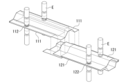
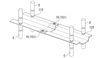
- FIG. 2 is a perspective view of a first simulation model (Comparative Example No. 1).
- FIG. 2 is a perspective view of a first simulation model (Comparative Example No. 1).
- FIG. 2 is a side view of a first simulation model (Comparative Example No. 1).
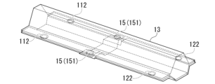
- FIG. 13 is a perspective view of a second simulation model (Invention Example No. 2).
- FIG. 13 is a perspective view of a second simulation model (Invention Example No. 2).
- FIG. 13 is a side view of the second simulation model (Invention Example No. 2).
- FIG. 13 is a perspective view of a third simulation model (Invention Example No. 3).
- FIG. 13 is a perspective view of a third simulation model (Invention Example No. 3).
- FIG. 13 is a side view of the third simulation model (Invention Example No. 3).
- FIG. 2 is a schematic diagram for explaining three-point bending conditions. 13 is a graph showing the results of a simulation.
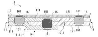
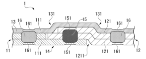
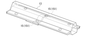
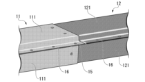
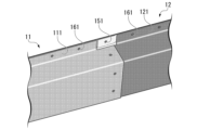
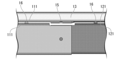
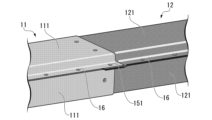
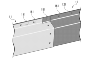
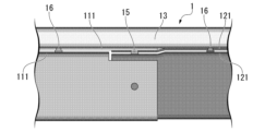
- a spot welding structure 1 is applied to, for example, a flange portion of a frame member of an automobile body, and as shown in FIG. 1 etc., includes a first lap joint 11 having two or more metal plates, a second lap joint 12 having two or more metal plates, a lap portion 14 in which one or more ends of the metal plates 111 of the first lap joint and one or more ends of the metal plates 121 of the second lap joint are overlapped, a main nugget 15 that joins the first lap joint 11 and the second lap joint 12 at the lap portion 14, and
- the joint comprises a metal plate-like member 13 overlapped on the lap joint 11, the second lap joint 12, and the wrap portion 14, and a plurality of secondary nuggets 16 that join the plate-like member 13 and the first lap joint 11, and the plate-like member 13 and the second lap joint 12, the number of metal plates joined by the main nugget 15 is three, the impression 151 of the main nugget 15 is only provided on the metal plates included in
- the spot welding structure 1 is a welded structure obtained by further spot welding the ends of the two lap joints.
- the two lap joints are referred to as a first lap joint 11 and a second lap joint 12.
- Any side of the two lap joints can be regarded as the first lap joint 11.
- the B-pillar may be regarded as the first lap joint 11, or the side sill may be regarded as the first lap joint 11.
- the lap joint on the left side of the paper is regarded as the first lap joint 11
- the lap joint on the right side of the paper is regarded as the second lap joint 12.
- the term "lap joint” means both the first lap joint 11 and the second lap joint 12 unless otherwise specified.
- a lap joint is a joint in which parts are placed approximately parallel and overlap each other.
- the parts of the lap joint are metal plates.
- a lap joint is a joint obtained by overlapping and welding multiple metal plates.
- An example of a lap joint is a frame member of an automobile body to which an inner frame structure is applied.
- the metal plate can have any shape suitable for spot welding.
- the term "metal plate” is a concept that includes not only flat metal plates, but also flat regions of metal components having a three-dimensional shape.
- the flange portion of a hat-shaped component is also considered to be a metal plate.
- the plate-shaped components described below are also a concept that includes flat regions of metal components having a three-dimensional shape.
- the number of metal plates in the lap joint is two.
- the number of metal plates in the lap joint can be any value equal to or greater than three.
- the main nugget 15 joins three metal plates. In FIG. 1, the main nugget 15 joins one metal plate 111 of the first lap joint 11 and two metal plates 121 of the second lap joint 12. Alternatively, the main nugget 15 may join two metal plates of the first lap joint 11 and one metal plate of the second lap joint 12.
- an indentation is formed so as to overlap the nugget.
- the indentation is a depression on the surface of the base material caused by the electrode tip as a result of spot welding.
- the indentation 151 of the main nugget 15 is only provided on the metal plate included in the first lap joint 11 or the second lap joint 12.
- the indentation 151 of the main nugget is not provided on the plate-like member 13 described below.
- the plate-like member 13 is outside the main nugget 15 described above.
- the main nugget 15 described above does not have the function of joining the plate-like member 13 to the first lap joint 11 or the second lap joint 12.
- the main nugget 15 is formed by spot welding (primary spot welding, described later) in which only the metal plate 111 of the first lap joint 11 and the metal plate 121 of the second lap joint 12 are to be welded. Therefore, the impression 151 of the main nugget 15 is not provided on the plate-like member 13.
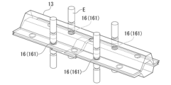
- the secondary nugget 16 is provided outside the lap portion 14. Therefore, the secondary nugget 16 does not join the first lap joint 11 and the second lap joint 12.
- the secondary nugget impression 161 is also necessarily provided outside the lap portion 14.
- the main nugget 15 that joins the first lap joint 11 and the second lap joint 12 joins three skeletal members (metal plates).
- the plate-shaped member 13 is outside the main nugget 15.
- the main nugget 15 is separated from the plate-shaped member 13. Therefore, there are three skeletal members (metal plates) that are directly involved in joining the first lap joint 11 and the second lap joint 12. As a result, the load transmission efficiency is dramatically improved in the spot welding structure 1 according to this embodiment.
- the spot welding structure 1 when manufacturing the spot welding structure 1 according to this embodiment, it is not necessary to grow the main nugget 15 up to the plate-shaped member 13. Therefore, in the spot welding (primary spot welding) for forming the main nugget 15, it is not necessary to make the welding current excessively large. This makes it possible to suppress the occurrence of expulsion and blowholes, and further increase the joint strength of the main nugget 15.
- a secondary nugget 16 that joins the plate-shaped member 13 to another member is provided outside the lap portion 14. This makes it possible to suppress poor joining of the plate-shaped member 13.
- the total thickness of the metal plate outside the wrap portion 14 is smaller than the total thickness of the metal plate in the wrap portion 14. Therefore, the sheet thickness ratio outside the wrap portion 14 is smaller than the sheet thickness ratio in the wrap portion 14.
- the spot welding structure 1 according to this embodiment When the spot welding structure 1 according to this embodiment is applied to the inner frame structure of an automobile body, the plate-like member 13 becomes the outer plate member of the vehicle body, and the first lap joint 11 and the second lap joint 12 become the skeletal members of the vehicle body.
- the spot welding structure 1 according to this embodiment can suppress poor joining of the outer plate members and increase the load transmission efficiency between the skeletal members.
- the distance d between the center of the secondary nugget 16 joining the plate-like member 13 and the first lap joint 11 and the center of the secondary nugget 16 joining the plate-like member 13 and the second lap joint 12 is 200 mm or less. This further improves the load transmission efficiency of the spot welding structure 1.
- the distance d may be 190 mm or less, 180 mm or less, 160 mm or less, or 140 mm or less.
- the center-to-center distance of the secondary nuggets 16 is determined by measuring the center-to-center distance of the indentations 161 of the secondary nuggets 16.
- the distance d between the center of the secondary nugget 16 joining the plate-like member 13 and the first lap joint 11 and the center of the secondary nugget 16 joining the plate-like member 13 and the second lap joint 12 means the minimum center-to-center distance of the secondary nuggets 16.
- the lap portion 14 is preferably a butt joint.
- a butt joint is understood to be a type of joint in which one member and/or part of a lap joint is stepped so that the base material surface is substantially flush (JIS Z 3001-1:2018).
- at least one of the metal plates 111 of the first lap joint 11 and the metal plate 121 of the second lap joint 12 has a butt joint in the lap portion 14, and two of the three metal plates joined by the main nugget 15 are preferably arranged on substantially the same plane outside the lap portion 14.
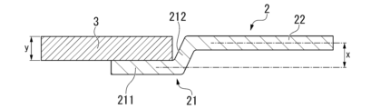
- a metal plate 2 having an edge processing portion 21 is stacked on a metal plate 3 without an edge processing portion.
- the edge processing portion 21 is formed, for example, by bending the metal plate 2 into a stepped shape.
- the edge processing portion 21 has a tip portion 211 and a connection portion 212.
- the portion of the metal plate 2 having the edge processing portion 21, excluding the edge processing portion 21, is referred to as a main body portion 22.
- the tip 211 of the cut section 21 is approximately parallel to the main body 22 of the metal plate 2, but is not on the same plane as the main body 22 of the metal plate 2.
- the plane that contains the tip 211 is separated a predetermined distance x from the plane that contains the main body 22. It is preferable that the predetermined distance x is approximately the same as the thickness y of the metal plate 3 that is overlapped with the cut section 21.
- the tip 211 constitutes the lap portion 14.
- the tip 211 has a width that is at least sufficient to allow spot welding.
- connection part 212 of the edge processing part 21 connects the tip part 211 of the edge processing part 21 and the main body part 22 of the metal plate 2.
- the connection part 212 forms a predetermined angle with the tip part 211 of the edge processing part 21 and the main body part 22 of the metal plate 2.
- the connection part 212 separates the plane containing the tip part 211 of the edge processing part 21 by a predetermined distance x from the plane containing the main body part 22 of the metal plate 2.
- the connection part 212 may be flat or curved.
- metal plate 3 is disposed in the space between a plane including tip 211 of seam processing portion 21 and a plane including main body 22 of metal plate 2.
- One surface of metal plate 2 having seam processing portion 21 is disposed substantially flush with one surface of metal plate 3 that overlaps seam processing portion 21.
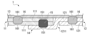
- the ends of the two metal plates 121 of the second lap joint 12 are provided with a seam 1211.
- the two metal plates 111 of the first lap joint 11 do not have a seam.
- the metal plate 111 on the upper side of the first lap joint 11 is disposed between the edge processing portion 1211 of the metal plate 121 on the upper side of the second lap joint 12 and the plate-shaped member 13.
- the edge processing portion 1211 of the metal plate 121 on the upper side of the second lap joint 12 is disposed between the edge processing portion 1211 of the metal plate 121 on the lower side of the second lap joint 12 and the metal plate 111 on the upper side of the first lap joint 11.
- the metal plate 111 of the first lap joint 11 and the metal plate 121 of the second lap joint 12 are disposed on approximately the same plane.
- the metal plate 111 on the upper side of the page of the first lap joint 11 (2) the edge processing portion 1211 of the metal plate 121 on the upper side of the page of the second lap joint 12, and (3) the edge processing portion 1211 of the metal plate 121 on the lower side of the page of the second lap joint 12 are overlapped in this order.
- the main nugget 15 joins the three metal plates of the lap portion 14.
- the metal plate 111 on the lower side of the page of the first lap joint 11 is excluded from the lap portion 14.
- a seam 1211 is provided only on the end of the metal plate 121 on the lower side of the paper of the second lap joint 12.
- the two metal plates 111 of the first lap joint 11 and the metal plate 121 on the upper side of the paper of the second lap joint 12 do not have a seam.
- the two metal plates 111 of the first lap joint 11 are arranged between the cutout portion 1211 of the metal plate 121 on the lower side of the paper surface of the second lap joint 12 and the plate-shaped member 13.
- the metal plate 111 of the first lap joint 11 and the metal plate 121 of the second lap joint 12 are arranged on approximately the same plane.
- the metal plate 111 on the upper side of the first lap joint 11 (2) the metal plate 111 on the lower side of the first lap joint 11, and (3) the edge processing portion 1211 of the metal plate 121 on the lower side of the second lap joint 12 are overlapped in this order.
- the main nugget 15 joins the three metal plates of the lap portion 14.
- the metal plate 121 on the upper side of the second lap joint 12 is excluded from the lap portion 14.
- a seam processing portion 1111 is provided at the end of the metal plate 111 on the lower side of the page of the first lap joint 11, and a seam processing portion 1211 is provided at the end of the metal plate 121 on the upper side of the page of the second lap joint 12.
- the metal plate 111 on the upper side of the page of the first lap joint 11 and the metal plate 121 on the lower side of the page of the second lap joint 12 do not have a seam processing portion.
- the metal plate 111 on the upper side of the first lap joint 11 is disposed between the edge processing portion 1211 of the metal plate 121 on the upper side of the second lap joint 12 and the plate-shaped member 13.
- the edge processing portion 1211 of the metal plate 121 on the upper side of the second lap joint 12 is disposed between the metal plate 111 on the upper side of the first lap joint 11 and the edge processing portion 1111 of the metal plate 111 on the lower side of the first lap joint 11.
- the metal plate 111 of the first lap joint 11 and the metal plate 121 of the second lap joint 12 are disposed on approximately the same plane.
- the metal plate 111 on the upper side of the page of the first lap joint 11 (2) the edge processing portion 1211 of the metal plate 121 on the upper side of the page of the second lap joint 12, and (3) the edge processing portion 1111 of the metal plate 111 on the lower side of the page of the first lap joint 11 are overlapped in this order.
- the main nugget 15 joins the three metal plates of the lap portion 14.
- the metal plate 121 on the lower side of the page of the second lap joint 12 is excluded from the lap portion 14.
- a seam 1211 is provided only on the end of the metal plate 121 on the upper side of the page of the second lap joint 12.
- the two metal plates 111 of the first lap joint 11 and the metal plate 121 on the lower side of the page of the second lap joint 12 do not have a seam.
- the two metal plates 111 of the first lap joint 11 are arranged between the cutout portion 1211 of the metal plate 121 on the upper side of the page of the second lap joint 12 and the plate-shaped member 13.
- the metal plate 111 of the first lap joint 11 and the metal plate 121 of the second lap joint 12 are arranged on approximately the same plane.
- the metal plate 111 on the upper side of the first lap joint 11 (2) the metal plate 111 on the lower side of the first lap joint 11, and (3) the edge processing portion 1211 of the metal plate 121 on the upper side of the second lap joint 12 are overlapped in this order.
- the main nugget 15 joins the three metal plates of the lap portion 14.
- the metal plate 121 on the lower side of the second lap joint 12 is excluded from the lap portion 14.
- the plate-like member 13 may have a seam processing portion.
- the two metal plates 121 of the second lap joint 12 are provided with a seam processing portion 1211. Furthermore, the plate-like member 13 is also provided with a seam processing portion 131.
- the two metal plates 111 of the first lap joint 11 do not have a seam processing portion.
- the edge processing portion 1211 of the metal plate 121 on the lower side of the paper of the second lap joint 12 is disposed between the edge processing portion 1211 of the metal plate 121 on the upper side of the paper of the second lap joint 12 and the metal plate 111 on the lower side of the paper of the first lap joint 11.
- the metal plate 111 of the first lap joint 11 and the metal plate 121 of the second lap joint 12 are disposed on approximately the same plane.
- the edge processing portion 1211 of the metal plate 121 on the upper side of the paper of the second lap joint 12 forms a convex portion facing the upper side of the paper.
- this convex portion is stored in the edge processing portion 131 of the plate-shaped member 13. Therefore, no large gap is generated between the plate-shaped member 13 and the main body portion 1112 of the metal plate 111 of the first lap joint 11 and/or the main body portion 1212 of the metal plate 121 of the second lap joint 12.
- a gap may be present between the plate-shaped member 13 and the first lap joint 11 and/or the second lap joint 12.
- the edged portion 1211 of the metal plate 121 on the upper side of the paper of the second lap joint 12 (2) the edged portion 1211 of the metal plate 121 on the lower side of the paper of the second lap joint 12, and (3) the metal plate 111 on the lower side of the paper of the first lap joint 11 are overlapped in this order.
- the main nugget 15 joins the three metal plates of the lap portion 14.
- the metal plate 111 on the upper side of the paper of the first lap joint 11 is excluded from the lap portion 14.
- Multiple main nuggets 15 may be provided in the lap portion 14.
- the two metal plates 121 of the second lap joint 12 are provided with a seam 1211.
- the two metal plates 111 of the first lap joint 11 do not have a seam.
- the metal plate 111 on the upper side of the page of the first lap joint 11 is disposed between the seam processing portion 1211 of the two metal plates 121 of the second lap joint 12 and the plate-like member 13.
- the metal plate 111 of the first lap joint 11 and the metal plate 121 of the second lap joint 12 are disposed on approximately the same plane.
- the metal plate 111 of the first lap joint 11 and the metal plate 121 of the second lap joint 12 are arranged on approximately the same plane, thereby further improving the load transmission efficiency.
- the number of joint interfaces between the first lap joint 11 and the second lap joint 12 may be two or more. By making the number of joint interfaces between the first lap joint 11 and the second lap joint 12 two or more, the rigidity of the spot welding structure 1 is further improved.
- the lap portion 14 is also divided into two.
- the metal plate 111 on the upper side of the paper of the first lap joint 11 11, the edge processing portion 1211 of the metal plate 121 on the upper side of the paper of the second lap joint 12, and the edge processing portion 1111 of the metal plate 111 on the lower side of the paper of the first lap joint 11 are stacked in this order.
- a main nugget 15 is formed to join the three metal plates.
- the edge processing portion 1211 of the metal plate 121 on the upper side of the paper of the second lap joint 12 forms a convex portion in the lap portion 14.
- the convex portion is housed inside the edge processing portion 131 provided on the plate-shaped member 13.
- the lap portion 14 is also divided into two.
- the metal plate 111 on the upper side of the paper of the first lap joint 11 11, the edge processing portion 1211 of the metal plate 121 on the upper side of the paper of the second lap joint 12, and the edge processing portion 1111 of the metal plate 111 on the lower side of the paper of the first lap joint 11 are overlapped in order.
- the metal plate 111 on the upper side of the paper of the first lap joint 11, the edge processing portion 1211 of the metal plate 121 on the upper side of the paper of the second lap joint 12, and the edge processing portion 1211 of the metal plate 121 on the lower side of the paper of the second lap joint 12 are overlapped in order.
- a main nugget 15 is formed to join the three metal plates.
- the wrap portion 14 is divided into two, and in each of the two wrap portions 14, a main nugget 15 is formed that joins the three metal plates, forming two joint structures. This further improves the load transmission efficiency. Also, two or more main nuggets 15 may be formed in each wrap portion 14. This further improves the load transmission efficiency.
- the spot welding structure 1 further includes an adhesive 17.
- the adhesive 17 is disposed between the plate-shaped member 13 and one or both of the first lap joint 11 and the second lap joint 12, for example, as shown in FIG. 6. This further increases the joint strength between the plate-shaped member 13 and other members.
- the adhesive 17 may also be provided between the metal plate 111 of the first lap joint 11 and the metal plate 121 of the second lap joint 12. This further increases the joint strength of the two lap joints and also increases the load transmission efficiency.
- the adhesive 17 may be disposed between the multiple metal plates 111 included in the first lap joint 11, or may be disposed between the multiple metal plates 121 included in the second lap joint 12. This further increases the joint strength of the first lap joint 11 and/or the second lap joint 12.
- the type of adhesive 17 is not particularly limited. Examples of the adhesive 17 include epoxy-based, rubber-based, silicone-based, or a mixture of these adhesives.
- the adhesive may be of the heat-curing or reaction-curing type, but when applied to automobile bodies, the adhesive is preferably of the heat-curing type that cures during the heat treatment step (140° C. to 190° C.) of electrodeposition coating.
- the spot welding structure 1 may further include an additional nugget 18 in the lap portion 14.
- the additional nugget 18 joins two or more of the metal plates and the plate-like members 13 included in the lap portion 14.
- the additional nugget 18 is similar to the main nugget 15 in that it is provided in the lap portion 14. However, unlike the main nugget 15, one of the two indentations of the additional nugget 18 is provided in the plate-like member 13.
- the additional nugget 18 is obtained by spot welding to the lap portion 14 in a state where the plate-like member 13 is further overlapped on the lap portion 14.
- the lap portion 14 When a plate-like member 13 is further layered on the lap portion 14, the lap portion 14 will contain four or more metal plates. In spot welding of such plate assemblies, expulsion is usually likely to occur. However, the plate gaps in the lap portion 14 are removed when the main nugget 15 and the secondary nugget 16 are formed. Therefore, expulsion caused by the plate gaps is suppressed when the additional nugget 18 is formed.
- the additional nugget 18 only needs to join at least two of the metal plates and the plate-like member 13 included in the lap portion 14.
- the additional nugget 18 does not need to grow to the plate-like member 13. That is, the additional nugget 18 does not need to join the plate-like member 13 to another member.
- the additional nugget 18 may press the plate-like member 13 to another member. Even if the additional nugget 18 is outside the plate-like member 13, the additional nugget 18 can have the effect of improving the joint strength and load transmission efficiency of the two lap joints.
- the additional nugget 18 may be provided apart from the main nugget 15.
- the additional nugget 18 and the main nugget 15 may be partially fused. An example of a cross section in which the additional nugget 18 and the main nugget 15 are partially fused is shown in FIG. 15.
- the spot welded structure 1 does not have to have the additional nugget 18 in the lap portion 14. That is, the plate-like member may be separated from the first lap joint and the second lap joint over the entire lap portion. By omitting the additional nugget 18, the manufacturing cost of the spot welded structure 1 can be reduced, and the time required to manufacture the spot welded structure 1 can be shortened.
- the first lap joint may have a joint outside the lap portion that joins only the metal plates of the first lap joint.
- the second lap joint may have a joint outside the lap portion that joins only the metal plates of the second lap joint.
- the joints are, for example, the nugget 112 of the first lap joint 11 and the nugget 122 of the second lap joint 12 shown in FIG. 1.
- the nugget 112 of the first lap joint 11 joins the metal plates 111 of the first lap joint 11, but does not join the first lap joint 11 to another member.
- the nugget 122 of the second lap joint 12 joins the metal plates 121 of the second lap joint 12, but does not join the second lap joint 12 to another member.
- the metal plates included in the lap joint may be joined by arc welded metal, seam welded metal, laser welded metal, or a combination of these.
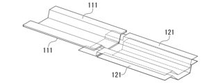
- a first manufacturing method of a spot welded structure 1 includes the following steps, as shown in FIGS. 8A to 8E: (S1) preparing a first lap joint 11 having two or more metal plates and a second lap joint 12 having two or more metal plates; (S2) a step of overlapping one or more ends of the metal plates 111 of the first lap joint and one or more ends of the metal plates 121 of the second lap joint to form a lap portion 14; (S3) a step of primarily spot welding the first lap joint 11 and the second lap joint 12 at the lap portion 14 to form a main nugget 15; (S4) a process of overlapping a metal plate-like member 13 on the lap portion 14 on which the first lap joint 11, the second lap joint 12, and the main nugget 15 are formed; (S5) a step of secondary spot welding the plate-like member 13 and the first lap joint 11, and the plate-like member 13 and the second lap joint 12 to form a plurality of secondary nugget
- a first lap joint 11 having two or more metal plates and a second lap joint 12 having two or more metal plates are prepared.
- the process of preparing the lap joint may be a process of manufacturing the first lap joint 11 having two or more metal plates and the second lap joint 12 having two or more metal plates.
- the process of manufacturing the lap joint is, for example, a spot welding process shown in FIG. 8A.
- the process of manufacturing the lap joint may be, for example, a laser welding process, a seam welding process, a lap arc welding process, or the like.
- a lap joint manufactured by another person may be used as the first lap joint 11 and the second lap joint 12.
- An example of the first lap joint and the second lap joint is a frame part of an automobile, and an example of the plate-like member 13 is an outer plate part of an automobile.
- first lap joint 11 and the second lap joint 12 it is preferable to shape these ends. For example, it is preferable to have only one of the two or more metal plates in the lap joint protrude. By machining the end of the lap joint or by positioning the end of the metal plate before manufacturing the lap joint, it is possible to have only one of the two or more metal plates in the lap joint protrude. It is also preferable to provide a seam processing portion in one or more of the two or more metal plates. The seam processing portion can be formed by machining the end of the metal plate before or after manufacturing the lap joint.
- first lap joint 11 illustrated in FIG. 8A only one of the two or more metal plates 111 protrudes.
- second lap joint 12 illustrated in FIG. 8A only one of the two or more metal plates 121 protrudes, and both of the two metal plates 121 have a seam.
- various aspects such as those illustrated in FIG. 1, FIG. 4A to FIG. 4E, and FIG. 5A to FIG. 5D can be applied to the ends of the first lap joint 11 and the second lap joint 12.
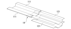
- the two lap joints are aligned so that the ends of the metal plates are inserted into the space formed by the seam processing portion.
- This alignment is also considered to be overlapping the ends of one or more of the metal plates 111 of the first lap joint and the ends of one or more of the metal plates 121 of the second lap joint.
- all of the actions for forming the lap portion 14 are considered to be actions of overlapping the ends of the metal plates.
- the first lap joint 11 and the second lap joint 12 are primarily spot welded at the lap portion 14 to form a main nugget 15.
- an impression 151 of the main nugget is formed in the metal plate disposed on the outermost surface of the lap portion 14 by the primary spot welding.
- the number of metal plates to be primarily spot welded is three. Therefore, it is preferable to use the area in the lap portion 14 where three metal plates are overlapped as the welding point for the primary spot welding.
- the number of times primary spot welding may be one, or two or more.
- the plate-like member 13 and the first lap joint 11, and the plate-like member 13 and the second lap joint 12 are secondarily spot welded to form a plurality of sub-nuggets 16.
- the welding points of the secondary spot welding are outside the lap portion 14.
- the secondary spot welding is performed at least once on the plate-like member 13 and the first lap joint 11, and at least once on the plate-like member 13 and the second lap joint 12.
- the total number of secondary spot welding may be three or more times.
- the first manufacturing method of the spot welded structure 1 according to the present embodiment three metal plates are overlapped at the joints of the two lap joints. Therefore, the first manufacturing method according to the present embodiment can firmly join the two lap joints. In addition, the spot welded structure 1 obtained by the first manufacturing method according to the present embodiment has excellent load transmission efficiency.
- the welding point in the secondary spot welding for joining the plate-shaped member 13 to the other member is outside the lap portion 14. Therefore, in the first manufacturing method according to this embodiment, the total thickness of the plate assembly in the secondary spot welding is also reduced. This also suppresses the occurrence of expulsion in the secondary spot welding. In addition, poor joining between the plate-shaped member 13 and the other member is avoided.
- FIGS. 9A to 9F A second manufacturing method of the spot welded structure 1 according to another embodiment of the present invention is as shown in FIGS. 9A to 9F .
- (s1) preparing a plate set in which two of the metal plates that are components of a first lap joint are overlapped at their ends;
- (s2) a step of overlapping an end of one of the metal plates that is a component of the second lap joint on an end of the plate assembly to form a lap portion;
- (s4) a step of overlapping and spot welding one metal plate of the second lap joint provided with the main nugget and the remaining metal plate of the second lap joint outside the lap portion to form a second lap joint;
- (s5) placing a metal plate-like member on the lap portion on which the first lap joint, the second lap joint, and
- the second manufacturing method differs from the first manufacturing method in that the first lap joint and the second lap joint are not formed before the primary spot welding is performed.
- the second manufacturing method is very similar to the first manufacturing method.
- the first manufacturing method and the second manufacturing method are identical in terms of the process of stacking the plate-like members and the subsequent processes. Therefore, in the following description of the second manufacturing method, matters that overlap with the first manufacturing method may be omitted. Suitable aspects of the first manufacturing method can be applied to the second manufacturing method.
- a plate set is prepared by overlapping two metal plates at their ends. These two metal plates are parts of a first lap joint. However, at this point, the metal plates of the first lap joint are not joined together.
- two of the metal plates that are components of the first lap joint and one of the metal plates that are components of the second lap joint are primarily spot welded at the lap portion. This brings the number of metal plates that are primarily spot welded to three.
- a main nugget is formed by the primary spot welding.
- a first lap joint is formed by the primary spot welding, which includes two metal plates and a main nugget that joins the two metal plates.
- one metal plate of the second lap joint in which the main nugget is provided is overlapped with the remaining metal plate of the second lap joint outside the lap portion, and the overlapped portion is spot welded to form the second lap joint.
- the second lap joint has only two metal plates.
- a second lap joint having three or more metal plates can be manufactured by overlapping and spot welding one metal plate of the second lap joint in which the main nugget is provided with two or more metal plates.
- additional spot welding may be performed on the first lap joint as shown in FIG. 9D.
- an additional metal plate may be added, so that the number of metal plates in the first lap joint is three or more.
- a metal plate-shaped member is placed on the lap portion where the first lap joint, the second lap joint, and the main nugget are formed. Furthermore, as shown in Fig. 9F, the plate-shaped member and the first lap joint, and the plate-shaped member and the second lap joint are secondarily spot welded to form a plurality of sub-nuggets. The welding points in the secondary spot welding are outside the lap portion. In the second manufacturing method, the process of welding the plate-shaped member to another member by placing it on top of it is substantially the same as in the first manufacturing method.
- the second manufacturing method of the spot welding structure 1 according to the present embodiment As in the first manufacturing method, in the second manufacturing method of the spot welding structure 1 according to the present embodiment, three metal plates are overlapped at the joint of the two lap joints. As in the first manufacturing method, in the second manufacturing method according to the present embodiment, the welding point in the secondary spot welding for joining the plate-shaped member 13 to another member is outside the lap portion 14. Therefore, according to the second manufacturing method according to the present embodiment, a spot welding structure with excellent load transmission efficiency is obtained. Furthermore, the second manufacturing method can suppress the occurrence of splashing. In addition, according to the second manufacturing method, poor joining between the plate-shaped member 13 and another member is avoided.
- the distance between the center of the welding point in the secondary spot welding of the plate-like member 13 and the first lap joint 11 and the center of the welding point in the secondary spot welding of the plate-like member 13 and the second lap joint 12 is 200 mm or less. This makes it possible to set the distance d between the center of the secondary nugget 16 joining the plate-like member 13 and the first lap joint 11 and the center of the secondary nugget 16 joining the plate-like member 13 and the second lap joint 12 to 200 mm or less. This further improves the load transmission efficiency of the spot welding structure 1.
- the distance between the centers of the welding points may be 190 mm or less, 180 mm or less, 160 mm or less, or 140 mm or less.
- the distance between the center of the welding point in the secondary spot welding of the plate-like member 13 and the first lap joint 11 and the center of the welding point in the secondary spot welding of the plate-like member 13 and the second lap joint 12 means the minimum center-to-center distance of the welding points.
- a seam processing portion may be provided at the end of one or more of the metal plates 111 of the first lap joint 11 and the metal plates 121 of the second lap joint 12, and when forming the lap portion 14, two of the three metal plates joined by the main nugget 15 may be arranged on approximately the same plane outside the lap portion 14.
- the load transmission efficiency is further improved.
- a specific example of the seam structure is the same as the preferred aspect of the spot welding structure 1 according to this embodiment, as exemplified in Figures 1 and 4A to 4E.
- the lap portion 14 may be subjected to primary spot welding a plurality of times.
- the plate combination may be the same in the plurality of primary spot weldings.
- the plate combination may be different in the plurality of primary spot weldings.
- a lap portion 14 in which two metal plates 111 of the first lap joint 11 and one metal plate 121 of the second lap joint 12 are overlapped, and a lap portion 14 in which one metal plate 111 of the first lap joint 11 and two metal plates 121 of the second lap joint 12 are overlapped may be formed, and primary spot welding may be performed on each of the plurality of lap portions 14.
- primary spot welding may also be performed multiple times on the lap portion 14.
- the plate combinations may be the same in the multiple primary spot weldings.
- the plate combinations may be different in the multiple primary spot weldings.
- the primary spot welding in order to perform multiple primary spot welding on different plate pairs, the primary spot welding must be performed in two stages. This is because only one of the metal plates of the second lap joint is included in the lap portion during the first primary spot welding. Therefore, during the first primary spot welding, a main nugget is formed that joins the two metal plates 111 of the first lap joint 11 and the one metal plate 121 of the second lap joint 12.
- the other metal plate 121 of the second lap joint 12 is overlapped on the one metal plate 121 of the second lap joint 12 to form an additional lap portion in which the one metal plate 111 of the first lap joint 11 and the two metal plates 121 of the second lap joint 12 are overlapped.
- the additional lap portion is subjected to primary spot welding to form a main nugget that joins the one metal plate 111 of the first lap joint 11 and the two metal plates 121 of the second lap joint 12.
- Either manufacturing method can be used to manufacture a spot welded structure 1 having a main nugget 15 that joins the two metal plates 111 of the first lap joint 11 to the one metal plate 121 of the second lap joint 12, and a main nugget 15 that joins the one metal plate 111 of the first lap joint 11 to the two metal plates 121 of the second lap joint 12. This further improves the load transmission efficiency of the spot welded structure 1.
- the lap portion 14 when performing multiple primary spot welding can be, for example, in the form shown in Figures 5A to 5D.
- the secondary spot welding may be a method of spot welding after applying a weld bond, i.e., an adhesive 17 to the joint interface in advance.
- the manufacturing method of the spot welding structure 1 may further include a step of applying an adhesive 17 between the plate-shaped member 13 and one or both of the first lap joint 11 and the second lap joint 12 after the primary spot welding and before overlapping the plate-shaped member 13 on the lap portion 14 on which the first lap joint 11, the second lap joint 12, and the main nugget 15 are formed. This makes it possible to manufacture the spot welding structure 1 in which the adhesive 17 is disposed between the plate-shaped member 13 and one or both of the first lap joint 11 and the second lap joint 12 as illustrated in FIG. 6 . Then, the joining strength between the plate-shaped member 13 and another member is further increased.
- the manufacturing method of the spot welded structure 1 may further include a step of performing additional spot welding on the lap portion 14 and the plate-like member 13 after the secondary spot welding. This makes it possible to manufacture a spot welded structure 1 that further has an additional nugget 18 in the lap portion 14 as shown in FIG. 7 .
- the lap portion 14 When a plate-shaped member 13 is further layered on the lap portion 14, the lap portion 14 will contain four or more metal plates.
- the metal plates referred to here include the metal plates that make up the plate-shaped member 13. In spot welding of such a plate assembly, expulsion is usually likely to occur. However, the plate gaps in the lap portion 14 are removed when the main nugget 15 and the secondary nugget 16 are formed. Therefore, expulsion caused by the plate gaps is suppressed during additional spot welding.
- the additional spot welding only needs to join at least two of the metal plates and the plate-like member 13 included in the lap portion 14.
- the additional spot welding does not need to grow the additional nugget 18 to the plate-like member 13. That is, the additional nugget 18 does not need to join the plate-like member 13 to another member.
- the additional nugget 18 may press the plate-like member 13 to another member. Even if the additional nugget 18 is outside the plate-like member 13, the additional nugget 18 can have the effect of improving the joint strength and load transmission efficiency of the two lap joints.
- the welding point of the additional spot welding may be separated from the welding point of the primary spot welding, or may overlap with the welding point of the primary spot welding.
- the manufacturing method of the spot welded structure 1 does not have to include a step of performing additional spot welding.
- all spot welding to the plate-like member may be performed outside the lap portion.
- the plate thickness ratio of the lap portion 14 is a value obtained by dividing the total thickness of the three metal plates and the plate-shaped member 13 at the location where the main nugget 15 is provided by the thickness of the plate-shaped member 13.
- the plate thickness ratio of the lap portion 14 is preferably within a range of 6.0 to 11.0.
- the larger the plate thickness ratio the more difficult it is to join the plate-shaped member 13.
- the spot welding structure 1 according to this embodiment and the manufacturing method thereof the plate-shaped member 13 is firmly joined outside the lap portion 14. Therefore, it is not essential that the plate-shaped member 13 is welded at the lap portion 14. Even if the plate thickness ratio of the lap portion 14 is large, poor joining of the plate-shaped member 13 does not become a problem.
- the thickness ratio of the secondary nugget forming portion is the total thickness of the multiple metal plates and the plate-like member 13 at the location where the secondary nugget 16 is provided, divided by the thickness of the plate-like member 13.
- the thickness ratio of the secondary nugget forming portion is preferably within the range of 3.0 to 6.0. More preferably, the upper limit is 5.5. The smaller the thickness ratio of the secondary nugget forming portion, the more likely it is that poor joining of the plate-like member 13 will be avoided.
- the plate thickness ratio is determined by measuring the thickness of the metal plate and plate-like member 13 in a cross section passing through the center of the indentation and perpendicular to the surface of the plate-like member 13. If the thickness of the metal plate and plate-like member 13 has been reduced by the indentation, the thickness measured at a location not affected by the indentation is used to calculate the plate thickness ratio.
- the type of the metal plate of the lap joint is not particularly limited.
- the type of the metal plate constituting the plate-shaped member 13 is also not particularly limited.
- any material that can be spot welded can be used as the metal plate of the lap joint and the metal plate constituting the plate-shaped member 13.
- a suitable material can be adopted depending on the application of the spot welding structure 1.
- the metal plate include a steel plate, an aluminum plate, and a stainless steel plate.
- a suitable example of a metal plate is a steel plate.
- one or more of the metal plates be high-strength steel plates.
- the thickness of the metal plates can be reduced while ensuring the strength of the spot welded structure 1 by using high-strength steel plates for one or more of the metal plates. By reducing the thickness of the metal plates, the spot welded structure 1 can be made lighter.
- the plate-shaped member 13 is mild steel and at least one of the metal plates included in the lap joint is a high-strength steel plate.
- the Vickers hardness of the plate-shaped member 13 is 150 HV or less, 140 HV or less, 130 HV or less, or 120 HV or less.
- the tensile strength of the plate-shaped member 13 is 440 MPa or less, 400 MPa or less, or 370 MPa or less.
- the hardness of at least one of the metal plates included in the lap joint is 300 HV or more, 380 HV or more, or 440 HV or more.
- the tensile strength of at least one of the metal plates included in the lap joint is 980 MPa or more, 1200 MPa or more, or 1350 MPa or more.
- the plate-shaped member 13 can be disposed on the outermost surface of the spot welding structure 1, and is therefore suitable, for example, for use as an exterior member of an automobile. By making the plate-shaped member 13 out of thin mild steel, the formability of the plate-shaped member 13 can be improved, and the aesthetic appearance of the automobile can be improved.
- the metal plates included in the lap joint are suitable for automobile frame parts, for example. By making one or more of the metal plates included in the lap joint out of high-strength steel plate, the collision safety of the automobile can be improved.
- the plate-shaped member 13 and the metal plate may have a surface treatment layer.
- the surface treatment layer may be, for example, a chemical conversion layer, a plating layer, etc.
- the configuration of the chemical conversion layer and the plating layer may be suitable for the components of the underlying metal plate.
- the plating layer is preferably, for example, a zinc-based plating layer, an aluminum-based plating layer, etc.
- the zinc-based plating layer is a plating layer having a Zn content of 30 mass% or more.
- Examples of the zinc-based plating layer include a hot-dip galvanized layer, an alloyed hot-dip galvanized layer, an electrogalvanized layer, a zinc-aluminum plating layer, a zinc-aluminum-magnesium plating layer, and a hot-stamped hot-dip galvanized layer.
- the aluminum-based plating layer is a plating layer having an Al content of 20 mass% or more.
- An example of a steel plate having an aluminum-based plating layer is an aluminum-silicon plated steel plate that has been hot-stamped.
- a layer of Al oxide, Ti oxide, or zinc oxide may be provided on the surface of the aluminum plating after hot stamping.
- the thickness of the metal plates of the lap joint there are no particular limitations on the thickness of the metal plates of the lap joint and the thickness of the plate-like member 13.
- the thickness of the plate-like member 13 is preferably 0.5 to 1.1 mm.
- the thickness of the metal plates of the lap joint is preferably 0.9 to 2.6 mm.
- the diameter of the main nugget 15 is not particularly limited, but is preferably, for example, 3 ⁇ t or more, 4 ⁇ t or more, or 5 ⁇ t or more. This increases the joining strength of the main nugget 15. On the other hand, from the viewpoint of suppressing the amount of heat input and further preventing the generation of spatter, it is preferable that the diameter of the main nugget 15 is 9 ⁇ t or less, 8 ⁇ t or less, or 7 ⁇ t or less.
- the numerical range of the diameter of the main nugget 15 can also be applied to the sub nugget 16, the additional nugget 18, the nugget 112 of the first lap joint, and the nugget 122 of the second lap joint.
- the nugget diameter refers to the diameter of the nugget measured along the joint interface in a cross-sectional test of the weld.
- t refers to the plate thickness of the thinner of the two steel plates that make up the joint interface at which the nugget diameter was measured.
- the use of the spot welding structure 1 according to the present embodiment is not particularly limited.
- a suitable use is a joint of a vehicle body to which an inner frame structure is applied.
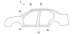
- Fig. 10 shows a joint of a vehicle body 4 of a vehicle.
- the spot welding structure 1 according to the present embodiment to the flanges of joints of the frame parts of the vehicle body, such as a joint 41 between an A-pillar lower and a side sill, a joint 42 between a B-pillar and a side sill, a joint 43 between a B-pillar and a roof rail, a joint 44 between an A-pillar lower and an A-pillar upper, a joint 45 between an A-pillar upper and a roof rail, a joint between a C-pillar and a roof rail, and a joint 46 between a C-pillar and a side sill, an automobile body with high load transmission efficiency can be realized.
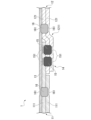
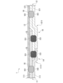
- the first and second plates from the bottom at the left end of the paper are two metal plates constituting the first lap joint.
- the first and second plates from the bottom at the right end of the paper are two metal plates constituting the second lap joint.
- the portion where the second nugget from the right of the paper is provided is a lap portion where an end portion of one of the metal plates of the first lap joint and an end portion of two or more of the metal plates of the second lap joint are overlapped.
- the second nugget from the right of the paper is a main nugget that joins the first lap joint and the second lap joint at the lap portion.
- the top plate on the paper is a plate-like member that is overlapped on the first lap joint, the second lap joint, and the lap portion.
- the first nugget from the right of the paper is a sub-nugget that joins the plate-like member and the first lap joint
- the first nugget from the left is a sub-nugget that joins the plate-like member and the second lap joint.
- the number of metal plates joined by the main nugget is three.
- the main nugget impression is provided only on the metal plates included in the first lap joint or the second lap joint.
- the plate-like member is located outside the main nugget.
- the secondary nugget is located outside the lap portion.
- the location where the second nugget from the left is provided corresponds to the lap portion where an end of one of the metal plates of the first lap joint and an end of one of the metal plates of the second lap joint are overlapped. Since this nugget is provided in the lap portion, it does not correspond to the secondary nugget. On the other hand, since the plate-like member is joined to this nugget, this nugget does not correspond to the main nugget. However, it is of course permissible to add such an additional nugget to the spot welded structure according to this embodiment. Furthermore, as described above, the spot welded joint in Fig.
- the spot welded joint 1 shown in Fig. 11 has all the characteristic features of the spot welded joint according to this embodiment. Therefore, even if the spot welded joint in Fig. 11 has an additional nugget, it is considered to be a spot welded joint according to this embodiment. If the second nugget from the left on the page is ignored, the spot welded joint 1 shown in Fig. 11 has a structure similar to that of Fig. 4A flipped from left to right.
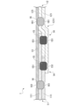
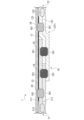
- the spot welded joint 1 shown in FIG. 12 has the same configuration as that shown in FIG.
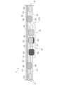
- the spot welded joint 1 shown in FIG. 13 has a configuration similar to that of FIG. 5A, but flipped left and right.
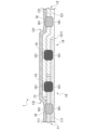
- the spot welded joint 1 shown in FIG. 14 has a configuration similar to that shown in FIG. 5B.
- the spot welded joint 1 shown in FIG. 15 has a configuration similar to that of FIG. 7 but flipped left and right.
- Example The effect of one embodiment of the present disclosure will be explained more specifically by an experiment using a simulation.
- the following condition is merely an example of a condition adopted to confirm the effect of the present disclosure.
- the present disclosure is not limited to this example of a condition.
- Various conditions may be adopted in the present disclosure as long as the purpose is achieved without departing from the gist of the disclosure.
- Models No. 1 to No. 3 are models assuming structural members in which hat-shaped members (metal plates) made of steel plates with thicknesses of 1.2 mm and 1.6 mm and tensile strengths of 1500 MPa are combined and the flanges are spot-welded.
- the outer plate member (plate-shaped member 13) is a steel plate with a thickness of 0.65 mm and tensile strength of 270 MPa.
- the spot welding structure of Comparative Example No. 1 is shown in Figures 16A to 16C.
- the spot welding structure of Comparative Example No. 1 is a simulation of a conventional spot welding structure. Note that in Figure 16A, the outer plate member (plate-shaped member 13) is omitted.
- the spot welding structure of Comparative Example No. 1 is a joint for only one of the two steel plates of each of the first lap joint 11 and the second lap joint 12.
- FIG. 1 is a model in which the steel plates of the two frame members (metal plate 111 on the upper side of the paper in Figure 16C and metal plate 121 on the upper side of the paper) and the outer plate member (plate-shaped member 13) are spot-welded together to form a nugget (main nugget 15). Note that the parts that look like holes in Figures 16A and 16B indicate spot welds on the simulation model.
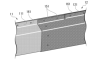
- the spot welding structure 1 of Example No. 2 is shown in Figures 17A to 17C.
- the spot welding structure 1 of Example No. 2 simulates the spot welding structure of the present disclosure.
- the outer plate member plate-shaped member 13
- the main nugget 15 that joins the first lap joint 11 and the second lap joint 12 joins three metal plates.
- the metal plate 111 on the upper side of the paper in Figure 17C, the metal plate 112 on the upper side of the paper, and the metal plate 112 on the lower side of the paper are stacked in this order.
- the spot welding structure of invention example No. 2 has the same configuration as in Figure 1. Note that the parts that look like holes in Figures 17A and 17B indicate spot welds on the simulation model.
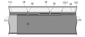
- Spot welding structure 1 of Example No. 3 is shown in Figures 18A to 18C. Spot welding structure 1 of Example No. 3 simulates the spot welding structure of the present disclosure. Note that in Figure 18A, the outer plate member (plate-shaped member 13) is omitted. In the spot welding structure 1 of Example No. 3, the lap portion 14 is divided into two. In the lap portion 14 on the side of the first lap joint 11, the metal plate 111 on the upper side of the first lap joint 11 on the page, the metal plate 111 on the lower side of the first lap joint 11 on the page, and the metal plate 121 on the lower side of the second lap joint 12 on the page are overlapped in that order.
- the metal plate 111 on the upper side of the first lap joint 11, the edged portion 1211 of the metal plate 121 on the upper side of the second lap joint 12, and the edged portion 1211 of the metal plate 121 on the lower side of the second lap joint 12 are overlapped in this order.
- a main nugget 15 is formed to join the three metal plates.
- the plate-shaped member 13 is outside the main nugget 15.
- the main nugget 15 is separated from the plate-shaped member 13. Therefore, in each of the two lap portions 14, the number of metal plates directly involved in the joining of the first lap joint 11 and the second lap joint 12 is three.
- the spot welding structure of the invention example No. 3 has a configuration similar to that of FIG. 5A. Note that the parts that look like holes in Figures 18A and 18B indicate spot welds on the simulation model.
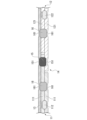
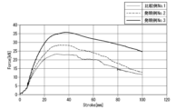
- the simulation model is a long structural member as shown in Fig. 19.
- the basic conditions for the simulation assuming three-point bending are as follows. In Nos. 1 and 2, the impactor was pressed against the position in the longitudinal direction of the structural member where the main nugget 15 was formed, and in No. 3, the impactor was pressed against the midpoint between the two main nuggets 15 in the longitudinal direction of the structural member.
Landscapes
- Engineering & Computer Science (AREA)
- Mechanical Engineering (AREA)
- Chemical & Material Sciences (AREA)
- Combustion & Propulsion (AREA)
- Transportation (AREA)
- Resistance Welding (AREA)
Abstract
Description
本開示は、スポット溶接構造、及びスポット溶接構造の製造方法に関する。
本願は、2023年9月19日に、日本に出願された特願2023-150978号に基づき優先権を主張し、その内容をここに援用する。
The present disclosure relates to spot welded structures and methods for manufacturing spot welded structures.
This application claims priority based on Japanese Patent Application No. 2023-150978, filed on September 19, 2023, the contents of which are incorporated herein by reference.
スポット溶接とは、重ね合わせた母材の金属を電極の先端で挟み、加圧力を加えながら電流を流し、発生したジュール熱で金属を溶融して接合する抵抗溶接である。スポット溶接などの重ね抵抗溶接において、溶接部に生じる溶融凝固した部分は、ナゲットと称される。 Spot welding is a type of resistance welding in which overlapping base metals are pinched between the tips of electrodes, pressure is applied while an electric current is passed through them, and the metals are melted and joined by the generated Joule heat. In lap resistance welding such as spot welding, the molten and solidified part that forms at the weld is called a nugget.
スポット溶接は非常に作業効率が高いので、種々の機械構造部品の製造のために用いられている。例えば、自動車の製造にあたっては、1台当たり数千点ものスポット溶接部が形成される。 Spot welding is very efficient, so it is used to manufacture a variety of mechanical structural parts. For example, thousands of spot welds are formed in each automobile.
特許文献1には、サイドシルを、アウターパネル及びインナーパネルと、この間にレインフォースメントを介在させると共に、両パネル、及びレインフォースメントのフランジ部同士を互いに重合構成する場合に、インナーパネルを長手方向に分割構成した分割パネル片の端末同士を結合して構成し、分割パネル片の各一端部に互いに重合可能なスポット溶接部を形成して、スポット溶接部をスポット溶接により接合すると共に、アウターパネルのフランジ部及びレインフォースメントのフランジ部と、両分割パネル片におけるフランジ部のうち一方とを、3枚重ね構成にて重合した上でスポット溶接により接合して構成した車両用車体フレームの結合部構造が開示されている。
特許文献2に開示される車両のセンタピラー構造は、センタピラーアウタとセンタピラーインナとで形成される内部空間上部にアッパリインホースメント、内部空間下部にロアリインホースメントをそれぞれ配設する。アッパリインホースメント下端部とロアリインホースメント上端部とを互いにオーバーラップ状に配設する。両リインホースメントの両側縁部の異なる一方側が切欠状とされて組み合わされる。アッパ補強主部がロア補強主部側に延設されて互いに重合状とされ、延設されたアッパ補強主部によって内部空間を上下に仕切る隔壁部を形成している。
The vehicle center pillar structure disclosed in
特許文献3に開示される自動車の車体上部の衝撃エネルギ吸収構造は、アウタパネルおよびインナパネルによって閉じ構造に形成され、前後方向へ伸びるルーフサイドレールを備える自動車の車体上部の衝撃エネルギを吸収する構造であって、アウタパネルおよびインナパネルの板厚より小さな板厚を有する鋼板製の2つのエネルギ吸収パネルを備える。2つのエネルギ吸収パネルは、同じ断面形状および同じ板厚であり、互いに隣接する端末部が重なり合うようにルーフサイドレールの前後方向へ配置され、かつ、腹部分を接合することなくフランジ部分でルーフサイドレールに接合される。
The impact energy absorbing structure for the upper body of an automobile disclosed in
特許文献4に開示される抵抗スポット溶接方法は、加圧力が設定した値まで達した後、低電流での予備通電を開始し、ギャップが潰れて無くなって、重ね合わせた全ての板が接した時に電極の位置を固定した後、本通電を開始し、その電極位置の固定によって本通電開始後の板組みの熱膨張を抑制することで加圧力を増加させ、その始めの設定加圧力Pおよび加圧力の最大値Pmが、Pm≧1.5×Pとなるようにする。
In the resistance spot welding method disclosed in
特許文献5には、重ね合わせた高強度薄鋼板を一対の電極によって挟み加圧力を加えながら抵抗スポット溶接をするにあたり、1点目を溶接後、電極の位置を移動し、1点目の溶接部がMf点以下の温度まで冷却された後に、1点目の溶接部に2点目の溶接部の一部が重なるように2点目の溶接を行なうことを特徴とする高強度薄鋼板の抵抗スポット溶接方法が開示されている。
近年、自動車の車体にインナーフレーム構造が適用される事例が増加している。インナーフレーム構造とは、自動車の車体を骨格部材(フレーム)及び外板部材(アウターパネル)に分け、車体全体のフレームを先に組み立ててから、アウターパネルを溶接する構造である。これにより、骨格部材が一層強固に接合される。 In recent years, there has been an increase in cases where an inner frame structure is applied to the body of an automobile. In an inner frame structure, the body of an automobile is divided into a skeletal member (frame) and an exterior panel member (outer panel), and the frame for the entire body is assembled first, after which the outer panel is welded. This allows the skeletal members to be joined even more firmly.
しかしながらスポット溶接には、4枚以上の重ね溶接で溶接不良が生じやすいという課題がある。自動車の車体の製造にあたっては、2つの骨格部材及び外板部材をスポット溶接する箇所で溶接不良が生じやすい。特に、外板部材が薄い軟鋼である場合、薄板までナゲットが成長しない場合がある。このような接合部では、スポット溶接の品質を安定させることが難しい。 However, spot welding has the problem that welding defects are likely to occur when welding four or more overlapping plates. When manufacturing an automobile body, welding defects are likely to occur at the points where two frame members and an exterior plate member are spot welded together. In particular, when the exterior plate member is made of thin mild steel, the nugget may not grow all the way to the thin plate. It is difficult to stabilize the quality of spot welding at such joints.
外板部材の接合不良を回避するための手段の一つは、溶接電流を大きくしてナゲットの成長を促進することである。しかし、大電流を通電するスポット溶接においては、散りが非常に生じやすい。 One way to avoid poor joints in exterior plate components is to increase the welding current to promote nugget growth. However, in spot welding, which uses a large current, expulsion is very likely to occur.
また、自動車部品の製造の際には、スプリングバックと呼ばれる現象に起因して、鋼板の間に隙間が生じやすい。鋼板の間に隙間がある板組にスポット溶接をすると、爆飛が生じ、ナゲット内に大きなブローホールが生じるおそれがある。ブローホールは、溶接部の接合強度を低下させる。 In addition, when manufacturing automotive parts, gaps are likely to occur between steel sheets due to a phenomenon known as springback. When spot welding is performed on a sheet assembly with gaps between the steel sheets, explosions can occur, and large blowholes can form in the nugget. Blowholes reduce the joint strength of the weld.
外板部材の接合不良を回避するための別の手段は、接合部に含まれる金属板の枚数を減少させて、接合部の合計厚さを小さくすることである。例えば図2に示されるように、骨格部材同士の接合部において鋼板を3枚重ねにすることが、従来から行われている。従来技術では、骨格部材(図2の第一の重ね継手11及び第二の重ね継手12)が有する2枚以上の鋼板のうち1枚だけを接合対象とする。そして、2つの骨格部材それぞれの鋼板(図2の紙面上側の金属板111、及び紙面下側の金属板121)と、外板部材(図2の板状部材13)との3枚を重ねてスポット溶接して、ナゲット(図2の主ナゲット15)を形成する。
Another method for avoiding poor joints of exterior plate members is to reduce the number of metal plates included in the joint to reduce the total thickness of the joint. For example, as shown in Figure 2, it has been conventional to overlap three steel plates at the joints between skeletal members. In the conventional technology, only one of the two or more steel plates in the skeletal members (
しかしながら、図2に例示されるようなスポット溶接構造においては、接合部を外板部材を含む3枚重ね構造にすることで、骨格部材の間の荷重伝達効率が低下する。これにより、車体の剛性の低下、及び接合強度の低下が生じうる。 However, in the spot welded structure shown in Figure 2, the joint is made of a three-ply structure including the outer plate member, which reduces the load transfer efficiency between the frame members. This can result in a decrease in the rigidity of the car body and a decrease in joint strength.
特許文献1~5に開示された技術は、いずれもインナーフレーム構造を想定しておらず、上述の課題を解決する手段を開示していない。
None of the technologies disclosed in
以上の事情に鑑みて、本開示は、外板部材の接合不良を抑制し、且つ骨格部材の間の荷重伝達効率が高いスポット溶接構造、及びスポット溶接構造の製造方法を提供することを目的とする。 In view of the above, the present disclosure aims to provide a spot welded structure that suppresses poor bonding of exterior plate members and has high load transfer efficiency between skeletal members, and a method for manufacturing the spot welded structure.
本開示の要旨は以下の通りである。 The gist of this disclosure is as follows:
(1)本開示の一態様に係るスポット溶接構造は、2枚以上の金属板を有する第一の重ね継手と、2枚以上の金属板を有する第二の重ね継手と、前記第一の重ね継手の前記金属板のうち1枚以上の端部、及び前記第二の重ね継手の前記金属板のうち1枚以上の端部が重ねられているラップ部と、前記第一の重ね継手及び前記第二の重ね継手を、前記ラップ部において接合する主ナゲットと、前記第一の重ね継手、前記第二の重ね継手、及び前記ラップ部に重ねられた、金属製の板状部材と、前記板状部材及び前記第一の重ね継手、並びに前記板状部材及び前記第二の重ね継手を接合する複数の副ナゲットと、を備え、前記主ナゲットが接合する前記金属板の枚数は3枚であり、前記主ナゲットの圧痕は、前記第一の重ね継手又は前記第二の重ね継手に含まれる前記金属板のみに設けられ、前記板状部材は、前記主ナゲットの外にあり、前記副ナゲットは、前記ラップ部の外にある。
(2)好ましくは、上記(1)に記載のスポット溶接構造では、前記板状部材及び前記第一の重ね継手を接合する前記副ナゲットの中心と、前記板状部材及び前記第二の重ね継手を接合する前記副ナゲットの中心との間隔が200mm以下である。
(3)好ましくは、上記(1)又は(2)に記載のスポット溶接構造では、前記第一の重ね継手の前記金属板、及び前記第二の重ね継手の前記金属板のうち1枚以上が、前記ラップ部においてせぎり加工部を有し、前記主ナゲットによって接合される3枚の前記金属板のうち2枚が、前記ラップ部の外において略同一面に配される。
(4)好ましくは、上記(1)~(3)の何れか一項に記載のスポット溶接構造では、前記第一の重ね継手と前記第二の重ね継手との接合界面の数が2以上である。
(5)好ましくは、上記(1)~(4)の何れか一項に記載のスポット溶接構造では、前記スポット溶接構造が、前記第一の重ね継手の2枚の前記金属板と、前記第二の重ね継手の1枚の前記金属板とを接合する前記主ナゲット、及び前記第一の重ね継手の1枚の前記金属板と、前記第二の重ね継手の2枚の前記金属板とを接合する前記主ナゲットを有する。
(6)好ましくは、上記(1)~(5)の何れか一項に記載のスポット溶接構造では、前記スポット溶接構造が、前記板状部材と、前記第一の重ね継手及び前記第二の重ね継手の一方又は両方との間に、接着剤をさらに有する。
(7)好ましくは、上記(1)~(6)の何れか一項に記載のスポット溶接構造では、前記スポット溶接構造が、前記ラップ部において、追加ナゲットをさらに有し、前記追加ナゲットは、前記ラップ部に含まれる前記金属板及び前記板状部材のうち2枚以上を接合し、前記板状部材に、前記追加ナゲットの圧痕が設けられている。
(8)好ましくは、上記(1)~(7)の何れか一項に記載のスポット溶接構造では、前記板状部材が、前記ラップ部の全体において、前記第一の重ね継手及び前記第二の重ね継手から分離している。
(9)好ましくは、上記(1)~(8)の何れか一項に記載のスポット溶接構造では、前記第一の重ね継手が、前記ラップ部の外において、前記第一の重ね継手の前記金属板のみを接合するナゲットを有し、前記第二の重ね継手が、前記ラップ部の外において、前記第二の重ね継手の前記金属板のみを接合するナゲットを有する。
(10)好ましくは、上記(1)~(9)の何れか一項に記載のスポット溶接構造では、前記第一の重ね継手及び前記第二の重ね継手が、自動車の骨格部品であり、前記板状部材が、前記自動車の外板部品である。
(1) A spot welding structure according to one aspect of the present disclosure includes a first lap joint having two or more metal plates, a second lap joint having two or more metal plates, a lap portion in which end portions of one or more of the metal plates of the first lap joint and end portions of one or more of the metal plates of the second lap joint are overlapped, a main nugget joining the first lap joint and the second lap joint at the lap portion, a metal plate-shaped member overlapped on the first lap joint, the second lap joint, and the lap portion, and a plurality of secondary nuggets joining the plate-shaped member and the first lap joint, as well as the plate-shaped member and the second lap joint, wherein the number of metal plates joined by the main nugget is three, an impression of the main nugget is provided only on the metal plates included in the first lap joint or the second lap joint, the plate-shaped member is outside the main nugget, and the secondary nugget is outside the lap portion.
(2) Preferably, in the spot welding structure described in (1) above, the distance between the center of the secondary nugget joining the plate-like member and the first lap joint and the center of the secondary nugget joining the plate-like member and the second lap joint is 200 mm or less.
(3) Preferably, in the spot welding structure described in (1) or (2) above, the metal plates of the first lap joint and one or more of the metal plates of the second lap joint have a seam processing portion in the lap portion, and two of the three metal plates joined by the main nugget are arranged in approximately the same plane outside the lap portion.
(4) Preferably, in the spot welded structure according to any one of (1) to (3) above, the number of joining interfaces between the first lap joint and the second lap joint is two or more.
(5) Preferably, in the spot welding structure described in any one of (1) to (4) above, the spot welding structure has a main nugget that joins two of the metal plates of the first lap joint and one of the metal plates of the second lap joint, and a main nugget that joins one of the metal plates of the first lap joint and two of the metal plates of the second lap joint.
(6) Preferably, in the spot welding structure described in any one of (1) to (5) above, the spot welding structure further has an adhesive between the plate-shaped member and one or both of the first lap joint and the second lap joint.
(7) Preferably, in the spot welding structure described in any one of (1) to (6) above, the spot welding structure further has an additional nugget in the wrap portion, the additional nugget joins two or more of the metal plates and the plate-like members included in the wrap portion, and an impression of the additional nugget is provided on the plate-like member.
(8) Preferably, in the spot welded structure described in any one of (1) to (7) above, the plate-shaped member is separated from the first lap joint and the second lap joint over the entire lap portion.
(9) Preferably, in the spot welding structure described in any one of (1) to (8) above, the first lap joint has a nugget outside the lap portion that joins only the metal plates of the first lap joint, and the second lap joint has a nugget outside the lap portion that joins only the metal plates of the second lap joint.
(10) Preferably, in the spot welded structure described in any one of (1) to (9) above, the first lap joint and the second lap joint are structural components of an automobile, and the plate-like member is an exterior panel component of the automobile.
(11)本発明の別の態様に係るスポット溶接構造の製造方法は、2枚以上の金属板を有する第一の重ね継手、及び2枚以上の金属板を有する第二の重ね継手を準備する工程と、前記第一の重ね継手の前記金属板のうち1枚以上の端部、及び前記第二の重ね継手の前記金属板のうち1枚以上の端部を重ね合わせてラップ部を形成する工程と、前記第一の重ね継手及び前記第二の重ね継手を、前記ラップ部において一次スポット溶接して、主ナゲットを形成する工程と、前記第一の重ね継手、前記第二の重ね継手、及び前記主ナゲットが形成された前記ラップ部に、金属製の板状部材を重ねる工程と、前記板状部材及び前記第一の重ね継手、並びに前記板状部材及び前記第二の重ね継手を二次スポット溶接して、複数の副ナゲットを形成する工程と、を備え、前記一次スポット溶接する前記金属板の枚数を3枚とし、前記二次スポット溶接における溶接点を前記ラップ部の外とする。
(12)本発明の別の態様に係るスポット溶接構造の製造方法は、第一の重ね継手の部品である金属板のうち2枚を、その端部において重ね合わせた板組を準備する工程と、前記板組の前記端部に、第二の重ね継手の部品である金属板のうち1枚の端部を重ね合わせてラップ部を形成する工程と、第一の重ね継手の前記部品である前記金属板のうち2枚と、前記第二の重ね継手の前記部品である前記金属板のうち1枚とを、前記ラップ部において一次スポット溶接して、主ナゲット及び前記第一の重ね継手を形成する工程と、前記主ナゲットが設けられた前記第二の重ね継手の1枚の前記金属板と、前記第二の重ね継手の残りの前記金属板とを、前記ラップ部の外において重ねてスポット溶接して、前記第二の重ね継手を形成する工程と、前記第一の重ね継手、前記第二の重ね継手、及び前記主ナゲットが形成された前記ラップ部に、金属製の板状部材を重ねる工程と、前記板状部材及び前記第一の重ね継手、並びに前記板状部材及び前記第二の重ね継手を二次スポット溶接して、複数の副ナゲットを形成する工程と、を備え、前記一次スポット溶接する前記金属板の枚数を3枚とし、前記二次スポット溶接における溶接点を前記ラップ部の外とする。
(13)好ましくは、上記(11)又は(12)に記載のスポット溶接構造の製造方法では、前記板状部材及び前記第一の重ね継手の前記二次スポット溶接における前記溶接点の中心と、前記板状部材及び前記第二の重ね継手の前記二次スポット溶接における前記溶接点の中心との間隔を200mm以下とする。
(14)好ましくは、上記(11)~(13)のいずれか一項に記載のスポット溶接構造の製造方法では、前記第一の重ね継手の前記金属板、及び前記第二の重ね継手の前記金属板のうち1枚以上の前記端部に、せぎり加工部を設け、前記ラップ部を形成する際に、前記主ナゲットによって接合される3枚の前記金属板のうち2枚を、前記ラップ部の外において略同一面に配する。
(15)好ましくは、上記(11)、(13)、(14)のいずれか一項に記載のスポット溶接構造の製造方法では、前記ラップ部を形成する際に、前記第一の重ね継手の2枚の前記金属板と、前記第二の重ね継手の1枚の前記金属板とを重ね合わせた前記ラップ部、及び前記第一の重ね継手の1枚の前記金属板と、前記第二の重ね継手の2枚の前記金属板とを重ね合わせた前記ラップ部を形成し、複数の前記ラップ部それぞれに前記一次スポット溶接をする。
(16)好ましくは、上記(12)~(14)のいずれか一項に記載のスポット溶接構造の製造方法では、前記主ナゲットを形成した後、前記第一の重ね継手の1枚の前記金属板と、前記第二の重ね継手の部品である2枚の前記金属板とを重ね合わせた追加ラップ部を形成するように、前記第二の重ね継手の残りの前記金属板を、前記主ナゲットが設けられた前記第二の重ね継手の1枚の前記金属板に重ねる工程と、前記追加ラップ部にさらに一次スポット溶接をして、さらに前記主ナゲットを形成する工程と、をさらに備える。
(17)好ましくは、上記(11)~(16)のいずれか一項に記載のスポット溶接構造の製造方法では、前記一次スポット溶接の後、且つ前記板状部材を前記第一の重ね継手、前記第二の重ね継手、及び前記主ナゲットが形成された前記ラップ部に重ねる前に、前記板状部材と、前記第一の重ね継手及び前記第二の重ね継手の一方又は両方との間に、接着剤を塗布する工程をさらに備える。
(18)好ましくは、上記(11)~(17)のいずれか一項に記載のスポット溶接構造の製造方法では、前記二次スポット溶接の後に、前記ラップ部及び前記板状部材に追加スポット溶接をする工程をさらに備える。
(19)好ましくは、上記(11)~(18)のいずれか一項に記載のスポット溶接構造の製造方法では、前記板状部材に対するスポット溶接を、全て前記ラップ部の外で行う。
(20)好ましくは、上記(11)~(19)のいずれか一項に記載のスポット溶接構造の製造方法では、前記第一の重ね継手及び前記第二の重ね継手が、自動車の骨格部品であり、前記板状部材が、前記自動車の外板部品である。
(11) A manufacturing method of a spot welded structure according to another aspect of the present invention includes the steps of preparing a first lap joint having two or more metal plates, and a second lap joint having two or more metal plates, overlapping end portions of one or more of the metal plates of the first lap joint and end portions of one or more of the metal plates of the second lap joint to form a lap portion, primary spot welding the first lap joint and the second lap joint at the lap portion to form a main nugget, overlapping a metal plate-shaped member on the lap portion on which the first lap joint, the second lap joint, and the main nugget are formed, and secondary spot welding the plate-shaped member and the first lap joint, as well as the plate-shaped member and the second lap joint to form a plurality of sub-nuggets, wherein the number of metal plates to be primary spot welded is three, and the welding points in the secondary spot welding are outside the lap portion.
(12) A manufacturing method of a spot welded structure according to another aspect of the present invention includes the steps of preparing a plate assembly by overlapping two of the metal plates that are components of a first lap joint at their ends, overlapping an end of one of the metal plates that are components of a second lap joint on the end of the plate assembly to form a lap portion, primarily spot welding the two of the metal plates that are components of the first lap joint and the one of the metal plates that are components of the second lap joint at the lap portion to form a main nugget and the first lap joint, and welding the second lap joint having the main nugget provided thereon. The method includes the steps of: overlapping and spot welding one of the metal plates and the remaining metal plate of the second lap joint outside the lap portion to form the second lap joint; overlapping a metal plate-shaped member on the lap portion on which the first lap joint, the second lap joint, and the main nugget are formed; and secondarily spot welding the plate-shaped member and the first lap joint, and the plate-shaped member and the second lap joint to form a plurality of secondary nuggets, wherein the number of metal plates to be primarily spot welded is three, and the welding points for the secondary spot welding are outside the lap portion.
(13) Preferably, in the manufacturing method of the spot welded structure described in (11) or (12) above, the distance between the center of the weld point in the secondary spot weld of the plate-shaped member and the first lap joint and the center of the weld point in the secondary spot weld of the plate-shaped member and the second lap joint is 200 mm or less.
(14) Preferably, in the manufacturing method of a spot welded structure described in any one of (11) to (13) above, a seam processing portion is provided on the end portions of one or more of the metal plates of the first lap joint and the metal plates of the second lap joint, and when forming the lap portion, two of the three metal plates joined by the main nugget are arranged in approximately the same plane outside the lap portion.
(15) Preferably, in the manufacturing method of the spot welded structure described in any one of (11), (13), and (14) above, when forming the lap portion, the lap portion is formed by overlapping two of the metal plates of the first lap joint with one of the metal plates of the second lap joint, and the lap portion is formed by overlapping one of the metal plates of the first lap joint with two of the metal plates of the second lap joint, and the primary spot welding is performed on each of the multiple lap portions.
(16) Preferably, in the manufacturing method of the spot welded structure described in any one of (12) to (14) above, after forming the main nugget, the method further includes a step of overlapping the remaining metal plate of the second lap joint onto the one metal plate of the second lap joint on which the main nugget is provided, so as to form an additional lap portion in which one of the metal plates of the first lap joint and two metal plates that are parts of the second lap joint are overlapped, and a step of further performing primary spot welding on the additional lap portion to further form the main nugget.
(17) Preferably, in the manufacturing method of a spot welded structure described in any one of (11) to (16) above, after the primary spot welding and before overlapping the plate-shaped member onto the first lap joint, the second lap joint, and the lap portion on which the main nugget is formed, an adhesive is applied between the plate-shaped member and one or both of the first lap joint and the second lap joint.
(18) Preferably, the method for manufacturing a spot welded structure described in any one of (11) to (17) above further includes a step of performing additional spot welding on the lap portion and the plate-like member after the secondary spot welding.
(19) Preferably, in the method for manufacturing a spot welded structure according to any one of (11) to (18) above, all spot welding to the plate-like member is performed outside the lap portion.
(20) Preferably, in the manufacturing method of a spot welded structure described in any one of (11) to (19) above, the first lap joint and the second lap joint are skeletal components of an automobile, and the plate-like member is an exterior panel component of the automobile.
本開示によれば、外板部材の接合不良を抑制し、且つ骨格部材の間の荷重伝達効率が高いスポット溶接構造、及びスポット溶接構造の製造方法を提供することができる。 This disclosure provides a spot welded structure that suppresses poor bonding of exterior plate members and has high load transfer efficiency between skeletal members, as well as a method for manufacturing the spot welded structure.
(1.スポット溶接構造1)
本開示の一態様に係るスポット溶接構造1は、例えば、自動車車体の骨格部材のフランジ部に適用され、図1等に示されるように、2枚以上の金属板を有する第一の重ね継手11と、2枚以上の金属板を有する第二の重ね継手12と、第一の重ね継手の金属板111のうち1枚以上の端部、及び第二の重ね継手の金属板121のうち1枚以上の端部が重ねられているラップ部14と、第一の重ね継手11及び第二の重ね継手12を、ラップ部14において接合する主ナゲット15と、第一の重ね継手11、第二の重ね継手12、及びラップ部14に重ねられた、金属製の板状部材13と、板状部材13及び第一の重ね継手11、並びに板状部材13及び第二の重ね継手12を接合する複数の副ナゲット16と、を備え、主ナゲット15が接合する金属板の枚数は3枚であり、主ナゲット15の圧痕151は、第一の重ね継手11又は第二の重ね継手12に含まれる金属板のみに設けられ、板状部材13は、主ナゲット15の外にあり、副ナゲット16は、ラップ部14の外にある。
(1. Spot Welded Structure 1)
A spot welding structure 1 according to one embodiment of the present disclosure is applied to, for example, a flange portion of a frame member of an automobile body, and as shown in FIG. 1 etc., includes a first lap joint 11 having two or more metal plates, a second lap joint 12 having two or more metal plates, a lap portion 14 in which one or more ends of the metal plates 111 of the first lap joint and one or more ends of the metal plates 121 of the second lap joint are overlapped, a main nugget 15 that joins the first lap joint 11 and the second lap joint 12 at the lap portion 14, and The joint comprises a metal plate-like member 13 overlapped on the lap joint 11, the second lap joint 12, and the wrap portion 14, and a plurality of secondary nuggets 16 that join the plate-like member 13 and the first lap joint 11, and the plate-like member 13 and the second lap joint 12, the number of metal plates joined by the main nugget 15 is three, the impression 151 of the main nugget 15 is only provided on the metal plates included in the first lap joint 11 or the second lap joint 12, the plate-like member 13 is located outside the main nugget 15, and the secondary nuggets 16 are located outside the wrap portion 14.
(第一の重ね継手11及び第二の重ね継手12)
スポット溶接構造1は、2つの重ね継手の端部をさらにスポット溶接することにより得られた溶接構造である。以下、説明の便宜のために、2つの重ね継手を第一の重ね継手11及び第二の重ね継手12と称する。2つの重ね継手のうち任意の側を第一の重ね継手11とみなすことができる。例えば、一方の重ね継手がBピラーであり、他方の重ね継手がサイドシルである場合、Bピラーを第一の重ね継手11であるとみなしてもよいし、サイドシルを第一の重ね継手11であるとみなしてもよい。図1等に例示されるスポット溶接構造1では、便宜的に、紙面左側の重ね継手を第一の重ね継手11であるとみなし、紙面右側の重ね継手を第二の重ね継手12であるとみなしている。以下、用語「重ね継手」は、とくに断りが無い限り、第一の重ね継手11及び第二の重ね継手12の両方を意味する。
(First lap joint 11 and second lap joint 12)
The
重ね継手とは、部品が略平行に置かれ、かつ、お互いに重なっている継手である。本実施形態においては、重ね継手の部品は金属板である。重ね継手は、複数の金属板を重ね溶接することにより得られた継手である。重ね継手は、例えば、インナーフレーム構造が適用された自動車の車体の骨格部材である。 A lap joint is a joint in which parts are placed approximately parallel and overlap each other. In this embodiment, the parts of the lap joint are metal plates. A lap joint is a joint obtained by overlapping and welding multiple metal plates. An example of a lap joint is a frame member of an automobile body to which an inner frame structure is applied.
金属板は、スポット溶接に適した、あらゆる形状を有することができる。換言すると、用語「金属板」とは、平板状の金属板のみならず、立体形状を有する金属部材の平板状領域をも包含する概念である。例えば、ハット型部材のフランジ部も、金属板とみなされる。後述する板状部材もまた、立体形状を有する金属部材の平板状領域を包含する概念である。 The metal plate can have any shape suitable for spot welding. In other words, the term "metal plate" is a concept that includes not only flat metal plates, but also flat regions of metal components having a three-dimensional shape. For example, the flange portion of a hat-shaped component is also considered to be a metal plate. The plate-shaped components described below are also a concept that includes flat regions of metal components having a three-dimensional shape.
なお、図1に例示されるスポット溶接構造1では、重ね継手が有する金属板の枚数は2である。一方、重ね継手が有する金属板の枚数は、3以上の任意の値とすることもできる。
In the
(ラップ部14、及び主ナゲット15)
第一の重ね継手11が有する金属板のうち1枚以上の端部、及び第二の重ね継手12が有する金属板のうち1枚以上の端部は、ラップ部14において重ねられている。第一の重ね継手11及び第二の重ね継手12は、ラップ部14においてスポット溶接されている。ラップ部14には、スポット溶接によって形成されて、第一の重ね継手11及び第二の重ね継手12を接合する主ナゲット15が設けられている。
(
Ends of one or more of the metal plates of the first lap joint 11 and end portions of one or more of the metal plates of the second lap joint 12 are overlapped at a
主ナゲット15は、3枚の金属板を接合する。図1では、主ナゲット15は、第一の重ね継手11の1枚の金属板111と、第二の重ね継手12の2枚の金属板121とを接合している。一方、主ナゲット15が、第一の重ね継手11の2枚の金属板と、第二の重ね継手12の1枚の金属板とを接合してもよい。
The
なお、スポット溶接の際には、ナゲットと重なるように圧痕が形成される。圧痕とは、スポット溶接の結果、電極チップによって生じた母材表面のくぼみである。主ナゲット15の圧痕151は、第一の重ね継手11又は第二の重ね継手12に含まれる金属板のみに設けられる。後述する板状部材13には、主ナゲットの圧痕151は設けられない。
When spot welding, an indentation is formed so as to overlap the nugget. The indentation is a depression on the surface of the base material caused by the electrode tip as a result of spot welding. The
(板状部材13)
本実施形態に係るスポット溶接構造1は、2つの重ね継手に加えて、金属製の板状部材13を有する。板状部材13は金属板から構成される。板状部材13は、第一の重ね継手11、第二の重ね継手12、及びラップ部14に重ねられている。板状部材13は、例えば、インナーフレーム構造が適用された自動車の車体の外板部材である。
(Plate-like member 13)
The
板状部材13は、上述した主ナゲット15の外にある。上述した主ナゲット15は、板状部材13と、第一の重ね継手11又は第二の重ね継手12とを接合する機能を有しない。主ナゲット15は、第一の重ね継手11の金属板111及び第二の重ね継手12の金属板121のみを溶接対象とするスポット溶接(後述する一次スポット溶接)によって形成されたものである。従って、主ナゲット15の圧痕151は、板状部材13には設けられない。
The plate-
(副ナゲット16)
板状部材13及び第一の重ね継手11は、副ナゲット16によって接合されている。また、板状部材13及び第二の重ね継手12も、副ナゲット16によって接合されている。これにより、第一の重ね継手11、第二の重ね継手12、及び板状部材13の全てが強固に接合される。板状部材13には、副ナゲット16の圧痕161が設けられる。
(Secondary Nugget 16)
The plate-
なお、副ナゲット16はラップ部14の外に設けられる。従って副ナゲット16は、第一の重ね継手11及び第二の重ね継手12を接合するものではない。副ナゲットの圧痕161もまた必然的に、ラップ部14の外に設けられる。
The
(作用効果)
図2に例示されるような従来のスポット溶接構造1においては、第一の重ね継手11及び第二の重ね継手12を接合する主ナゲット15は、2枚の金属板及び板状部材を接合するものとされていた。第一の重ね継手11及び第二の重ね継手12の接合に直接的に関与する骨格部材(金属板)は、2枚だけである。この場合、スポット溶接構造1の荷重伝達効率を十分に高めることが困難であった。
(Action and Effect)
In a conventional
図1に例示されるような本実施形態に係るスポット溶接構造1においては、第一の重ね継手11及び第二の重ね継手12を接合する主ナゲット15は、3枚の骨格部材(金属板)を接合する。そして、本実施形態に係るスポット溶接構造1においては、板状部材13が主ナゲット15の外にある。主ナゲット15は板状部材13から離隔されている。そのため、第一の重ね継手11及び第二の重ね継手12の接合に直接的に関与する骨格部材(金属板)は、3枚となっている。これにより、本実施形態に係るスポット溶接構造1においては、荷重伝達効率が飛躍的に高められている。
In the
また、本実施形態に係るスポット溶接構造1の製造の際には、板状部材13まで主ナゲット15を成長させる必要が無い。従って、主ナゲット15を形成するためのスポット溶接(一次スポット溶接)において、溶接電流を過剰に大きくする必要が無い。これにより、散り及びブローホールの発生を抑制し、主ナゲット15の接合強度を一層高めることができる。
Furthermore, when manufacturing the
さらに、本実施形態に係るスポット溶接構造1においては、板状部材13と他の部材と接合する副ナゲット16がラップ部14の外に設けられている。これにより、板状部材13の接合不良を抑制することができる。
Furthermore, in the
この理由は、板厚比によって説明される。板厚比は、スポット溶接の対象とされる板組の合計厚さを、板組の表面に配された金属板のうち薄い方の厚さで割って算出される値である。板組の表面に配された金属板の厚さが同一である場合は、その厚さで板組の合計厚さを割った値が板厚比である。板厚比は、スポット溶接のしやすさの指標として用いられる。板厚比が大きいほど、板組の表面に配された金属板までナゲットを成長させることが難しい。板組の表面に配された金属板までナゲットが成長しなかった場合、当該金属板はこれに隣接する金属板と接合されなくなる。従って、板厚比が大きいほど、接合不良が生じやすい。 The reason for this is explained by the plate thickness ratio. The plate thickness ratio is a value calculated by dividing the total thickness of the plate assembly to be spot welded by the thickness of the thinner of the metal plates arranged on the surface of the plate assembly. If the metal plates arranged on the surface of the plate assembly have the same thickness, the plate thickness ratio is the value obtained by dividing the total thickness of the plate assembly by the thinner thickness. The plate thickness ratio is used as an indicator of the ease of spot welding. The larger the plate thickness ratio, the more difficult it is to grow a nugget to the metal plate arranged on the surface of the plate assembly. If a nugget does not grow to the metal plate arranged on the surface of the plate assembly, that metal plate will not be joined to the adjacent metal plate. Therefore, the larger the plate thickness ratio, the more likely it is that poor joining will occur.
ラップ部14における金属板の合計厚さよりも、ラップ部14の外における金属板の合計厚さの方が小さい。従って、ラップ部14における板厚比よりも、ラップ部14の外における板厚比の方が小さい。ラップ部14の外部に副ナゲット16を設けることにより、板状部材13の接合不良をきわめて効果的に抑制することができる。
The total thickness of the metal plate outside the
本実施形態に係るスポット溶接構造1を、自動車の車体のインナーフレーム構造に適用した場合、板状部材13が車体の外板部材となり、第一の重ね継手11及び第二の重ね継手12が車体の骨格部材となる。本実施形態に係るスポット溶接構造1によれば、外板部材の接合不良を抑制し、且つ骨格部材の間の荷重伝達効率を高めることができる。
When the
以上、本実施形態に係るスポット溶接構造1の、最も基本的な態様について説明した。以下、一層好ましい態様について説明する。
The above describes the most basic aspect of the
(副ナゲットの間隔)
板状部材13及び第一の重ね継手11を接合する副ナゲット16の中心と、板状部材13及び第二の重ね継手12を接合する副ナゲット16の中心との間隔dが200mm以下であることが好ましい。これにより、スポット溶接構造1の荷重伝達効率が一層改善される。当該間隔dが190mm以下、180mm以下、160mm以下、又は140mm以下であってもよい。なお、副ナゲット16の中心間距離は、副ナゲット16の圧痕161の中心間距離を測定することにより求められる。
(Spacing between secondary nuggets)
It is preferable that the distance d between the center of the
第一の重ね継手11、及び第二の重ね継手12に副ナゲット16が複数設けられる場合がある。この場合、板状部材13及び第一の重ね継手11を接合する副ナゲット16の中心と、板状部材13及び第二の重ね継手12を接合する副ナゲット16の中心との間隔dとは、副ナゲット16の中心間距離の最小値を意味する。
There may be multiple
(せぎり構造)
ラップ部14は、せぎり継手とされていることが好ましい。一般に、せぎり継手とは、重ね継手の一方の部材及び/又は部品に段をつけ、母材面がほぼ同一平面になるようにした継手の形式であると理解される(JIS Z 3001-1:2018)。本実施形態に係るスポット溶接構造においては、第一の重ね継手11の金属板111、及び第二の重ね継手12の金属板121のうち1枚以上が、ラップ部14においてせぎり加工部を有し、主ナゲット15によって接合される3枚の金属板のうち2枚が、ラップ部14の外において略同一面に配されることが好ましい。
(Sticky structure)
The
以下、図3を参照しながら、せぎり構造について詳細に説明する。図3のせぎり構造では、せぎり加工部21を有する金属板2と、せぎり加工部を有しない金属板3とが重ねられている。せぎり加工部21は、例えば金属板2を階段状に折り曲げ加工することにより形成される。せぎり加工部21は、先端部211と、接続部212とを有する。以下の説明において、せぎり加工部21を有する金属板2のうち、せぎり加工部21を除く部分を、本体部22と称する。
The edge structure will be described in detail below with reference to Figure 3. In the edge structure of Figure 3, a
せぎり加工部21の先端部211は、金属板2の本体部22と略平行であるが、金属板2の本体部22と同一面上にはない。先端部211が含まれる平面は、本体部22が含まれる平面に対して所定の距離xだけ離隔されている。所定の距離xは、せぎり加工部21と重ねられる金属板3の板厚yと略同一にすることが好ましい。先端部211は、ラップ部14を構成する。先端部211は、少なくともスポット溶接することが可能な程度の幅を有する。
The
せぎり加工部21の接続部212は、せぎり加工部21の先端部211と、金属板2の本体部22とを接続する。接続部212は、せぎり加工部21の先端部211及び金属板2の本体部22に対して所定の角度をなしている。これにより接続部212は、せぎり加工部21の先端部211が含まれる平面を、金属板2の本体部22が含まれる平面に対して所定の距離xだけ離隔させる。なお、接続部212は平面状であっても曲面状であってもよい。
The
図3のせぎり構造では、せぎり加工部21の先端部211が含まれる平面と、金属板2の本体部22が含まれる平面との間の空間に金属板3が配置される。そして、せぎり加工部21を有する金属板2の一方の表面は、せぎり加工部21と重ねられる金属板3の一方の表面と、略同一平面上に配される。
In the seam structure of FIG. 3,
次に、図1、及び図4A~図4Eを参照しながら、本実施形態に係るスポット溶接構造におけるせぎり構造の具体例について説明する。 Next, a specific example of the weld structure in the spot welding structure according to this embodiment will be described with reference to Figure 1 and Figures 4A to 4E.
図1のスポット溶接構造1では、第二の重ね継手12の2枚の金属板121の端部にせぎり加工部1211が設けられている。第一の重ね継手11の2枚の金属板111はせぎり加工部を有しない。
In the
図1のスポット溶接構造1では、第二の重ね継手12の紙面上側の金属板121のせぎり加工部1211と、板状部材13との間に、第一の重ね継手11の紙面上側の金属板111が配されている。また、第二の重ね継手12の紙面下側の金属板121のせぎり加工部1211と、第一の重ね継手11の紙面上側の金属板111との間に、第二の重ね継手12の紙面上側の金属板121のせぎり加工部1211が配されている。これにより、第一の重ね継手11の金属板111と、第二の重ね継手12の金属板121とは、略同一平面上に配される。
In the
図1のスポット溶接構造1のラップ部14では、(1)第一の重ね継手11の紙面上側の金属板111、(2)第二の重ね継手12の紙面上側の金属板121のせぎり加工部1211、及び(3)第二の重ね継手12の紙面下側の金属板121のせぎり加工部1211が順に重ねられている。主ナゲット15は、ラップ部14の3枚の金属板を接合している。第一の重ね継手11の紙面下側の金属板111は、ラップ部14からは除外されている。
In the
図4Aのスポット溶接構造1では、第二の重ね継手12の紙面下側の金属板121の端部のみにせぎり加工部1211が設けられている。第一の重ね継手11の2枚の金属板111、及び第二の重ね継手12の紙面上側の金属板121はせぎり加工部を有しない。
In the
図4Aのスポット溶接構造1では、第二の重ね継手12の紙面下側の金属板121のせぎり加工部1211と、板状部材13との間に、第一の重ね継手11の2枚の金属板111が配されている。これにより、第一の重ね継手11の金属板111と、第二の重ね継手12の金属板121とは、略同一平面上に配される。
In the
図4Aのスポット溶接構造1のラップ部14では、(1)第一の重ね継手11の紙面上側の金属板111、(2)第一の重ね継手11の紙面下側の金属板111、及び(3)第二の重ね継手12の紙面下側の金属板121のせぎり加工部1211が順に重ねられている。主ナゲット15は、ラップ部14の3枚の金属板を接合している。第二の重ね継手12の紙面上側の金属板121は、ラップ部14からは除外されている。
In the
図4Bのスポット溶接構造1では、第一の重ね継手11の紙面下側の金属板111の端部にせぎり加工部1111が設けられ、かつ第二の重ね継手12の紙面上側の金属板121の端部にせぎり加工部1211が設けられている。第一の重ね継手11の紙面上側の金属板111、及び第二の重ね継手12の紙面下側の金属板121はせぎり加工部を有しない。
In the
図4Bのスポット溶接構造1では、第二の重ね継手12の紙面上側の金属板121のせぎり加工部1211と、板状部材13との間に、第一の重ね継手11の紙面上側の金属板111が配されている。また、第一の重ね継手11の紙面上側の金属板111と、第一の重ね継手11の紙面下側の金属板111のせぎり加工部1111との間に、第二の重ね継手12の紙面上側の金属板121のせぎり加工部1211が配されている。これにより、第一の重ね継手11の金属板111と、第二の重ね継手12の金属板121とは、略同一平面上に配される。
In the
図4Bのスポット溶接構造1のラップ部14では、(1)第一の重ね継手11の紙面上側の金属板111、(2)第二の重ね継手12の紙面上側の金属板121のせぎり加工部1211、及び(3)第一の重ね継手11の紙面下側の金属板111のせぎり加工部1111が順に重ねられている。主ナゲット15は、ラップ部14の3枚の金属板を接合している。第二の重ね継手12の紙面下側の金属板121は、ラップ部14からは除外されている。
In the
図4Cのスポット溶接構造1では、第二の重ね継手12の紙面上側の金属板121の端部のみにせぎり加工部1211が設けられている。第一の重ね継手11の2枚の金属板111、及び第二の重ね継手12の紙面下側の金属板121はせぎり加工部を有しない。
In the
図4Cのスポット溶接構造1では、第二の重ね継手12の紙面上側の金属板121のせぎり加工部1211と、板状部材13との間に、第一の重ね継手11の2枚の金属板111が配されている。これにより、第一の重ね継手11の金属板111と、第二の重ね継手12の金属板121とは、略同一平面上に配される。
In the
図4Cのスポット溶接構造1のラップ部14では、(1)第一の重ね継手11の紙面上側の金属板111、(2)第一の重ね継手11の紙面下側の金属板111、及び(3)第二の重ね継手12の紙面上側の金属板121のせぎり加工部1211が順に重ねられている。主ナゲット15は、ラップ部14の3枚の金属板を接合している。第二の重ね継手12の紙面下側の金属板121は、ラップ部14からは除外されている。
In the
板状部材13がせぎり加工部を有してもよい。図4Dのスポット溶接構造では、第二の重ね継手12の2枚の金属板121にせぎり加工部1211が設けられている。さらに、板状部材13にもせぎり加工部131が設けられている。第一の重ね継手11の2枚の金属板111はせぎり加工部を有しない。
The plate-
図4Dのスポット溶接構造1では、第二の重ね継手12の紙面上側の金属板121のせぎり加工部1211と、第一の重ね継手11の紙面下側の金属板111との間に、第二の重ね継手12の紙面下側の金属板121のせぎり加工部1211が配されている。これにより、第一の重ね継手11の金属板111と、第二の重ね継手12の金属板121とは、略同一平面上に配される。
In the
なお、図4Dのスポット溶接構造1のラップ部14において、第二の重ね継手12の紙面上側の金属板121のせぎり加工部1211は、紙面上側に向けた凸部を形成している。しかし、この凸部は、板状部材13のせぎり加工部131に収納されている。従って、板状部材13と第一の重ね継手11の金属板111の本体部1112及び/又は第二の重ね継手12の金属板121の本体部1212との間に、大きな隙間が生じることはない。なお、スポット溶接構造1のラップ部14においては、板状部材13と第一の重ね継手11及び/又は第二の重ね継手12との間に隙間があってもよい。板状部材13と第一の重ね継手11及び/又は第二の重ね継手12との間に隙間を設けることで、スポット溶接構造1のラップ部14の剛性が向上する。
In the
図4Dのスポット溶接構造1のラップ部14では、(1)第二の重ね継手12の紙面上側の金属板121のせぎり加工部1211、(2)第二の重ね継手12の紙面下側の金属板121のせぎり加工部1211、及び(3)第一の重ね継手11の紙面下側の金属板111が順に重ねられている。主ナゲット15は、ラップ部14の3枚の金属板を接合している。第一の重ね継手11の紙面上側の金属板111は、ラップ部14からは除外されている。
In the
複数の主ナゲット15が、ラップ部14に設けられてもよい。図4Eのスポット溶接構造1では、第二の重ね継手12の2枚の金属板121にせぎり加工1211が設けられている。第一の重ね継手11の2枚の金属板111はせぎり加工部を有しない。
Multiple
図4Eのスポット溶接構造1では、第二の重ね継手12の2枚の金属板121のせぎり加工部1211と、板状部材13との間に、第一の重ね継手11の紙面上側の金属板111が配されている。これにより、第一の重ね継手11の金属板111と、第二の重ね継手12の金属板121とは、略同一平面上に配される。
In the
図4Eのスポット溶接構造1のラップ部14では、(1)第一の重ね継手11の紙面上側の金属板111、(2)第二の重ね継手12の紙面上側の金属板121のせぎり加工部1211、及び(3)第二の重ね継手12の紙面下側の金属板121のせぎり加工部1211が順に重ねられている。主ナゲット15は2つ存在し、2つの主ナゲット15は、ラップ部14の3枚の金属板を接合している。第一の重ね継手11の紙面下側の金属板111は、ラップ部14からは除外されている。
In the
いずれの構成においても、第一の重ね継手11の金属板111と、第二の重ね継手12の金属板121とが略同一平面上に配されることにより、荷重伝達効率が一層高められる。
In either configuration, the
図1、図4A、図4C、図4D、及び図4Eに例示されるスポット溶接構造1では、第一の重ね継手11と第二の重ね継手12との接合界面は1枚だけである。一方、第一の重ね継手11と第二の重ね継手12との接合界面の数が2以上であってもよい。第一の重ね継手11と第二の重ね継手12との接合界面の数を2以上とすることにより、スポット溶接構造1の剛性が一層向上する。
In the
接合界面の数が2以上であるスポット溶接構造1の一例は、図4Bに示されるスポット溶接構造1である。図4Bのスポット溶接構造1では、主ナゲット15が形成された箇所において、第一の重ね継手11の2枚の金属板111の間に、第二の重ね継手12の1枚の金属板121が挟まれている。
An example of a
また、接合界面の数が2以上であるスポット溶接構造1の別の例は、図5A~図5Dに示されるように、複数の主ナゲット15が接合する3枚の金属板が異なっているスポット溶接構造1である。具体的には、図5A~図5Dに示されるスポット溶接構造1においては、一部の主ナゲット15が、第一の重ね継手11の2枚の金属板111と、第二の重ね継手12の1枚の金属板121とを接合するものであり、その他の主ナゲット15が、第一の重ね継手11の1枚の金属板111と、第二の重ね継手12の2枚の金属板121とを接合するものであることが好ましい。これにより、スポット溶接構造1の荷重伝達効率が一層改善される。さらに、第一の重ね継手11と第二の重ね継手12との接合界面の数が2以上となり、スポット溶接構造1の剛性が一層改善される。
Another example of a
図5Aに例示されるスポット溶接構造1では、ラップ部14が2つに分割されている。第一の重ね継手11の側のラップ部14では、第一の重ね継手11の紙面上側の金属板111、第一の重ね継手11の紙面下側の金属板111、及び第二の重ね継手12の紙面下側の金属板121のせぎり加工部1211が順に重ねられている。第二の重ね継手12の側のラップ部14では、第一の重ね継手11の紙面上側の金属板111、第二の重ね継手12の紙面上側の金属板121のせぎり加工部1211、及び第二の重ね継手12の紙面下側の金属板121のせぎり加工部1211が順に重ねられている。2つのラップ部14それぞれにおいて、3枚の金属板を接合する主ナゲット15が形成されている。
In the
図5Bに例示されるスポット溶接構造1でも、ラップ部14が2つに分割されている。第一の重ね継手11の側のラップ部14では、第一の重ね継手11の紙面上側の金属板111、第二の重ね継手12の紙面上側の金属板121のせぎり加工部1211、及び第一の重ね継手11の紙面下側の金属板111のせぎり加工部1111が順に重ねられている。第二の重ね継手12の側のラップ部14では、第二の重ね継手12の紙面上側の金属板121の本体部1212、第二の重ね継手12の紙面下側の金属板121、及び第一の重ね継手11の紙面下側の金属板111のせぎり加工部1111が順に重ねられている。2つのラップ部14それぞれにおいて、3枚の金属板を接合する主ナゲット15が形成されている。
In the
図5Cに例示されるスポット溶接構造1でも、ラップ部14が2つに分割されている。第一の重ね継手11の側のラップ部14では、第二の重ね継手12の紙面上側の金属板121のせぎり加工部1211、第一の重ね継手11の紙面上側の金属板111、及び第一の重ね継手11の紙面下側の金属板111が順に重ねられている。第二の重ね継手12の側のラップ部14では、第二の重ね継手12の紙面上側の金属板121のせぎり加工部1211、第二の重ね継手12の紙面下側の金属板121のせぎり加工部1211、及び第一の重ね継手11の紙面下側の金属板111が順に重ねられている。2つのラップ部14それぞれにおいて、3枚の金属板を接合する主ナゲット15が形成されている。また、第二の重ね継手12の紙面上側の金属板121のせぎり加工部1211は、ラップ部14において凸部を形成している。凸部は、板状部材13に設けられたせぎり加工部131の内部に収納されている。
5C, the
図5Dに例示されるスポット溶接構造1でも、ラップ部14が2つに分割されている。第一の重ね継手11の側のラップ部14では、第一の重ね継手11の紙面上側の金属板111、第二の重ね継手12の紙面上側の金属板121のせぎり加工部1211、及び第一の重ね継手11の紙面下側の金属板111のせぎり加工部1111が順に重ねられている。第二の重ね継手12の側のラップ部14では、第一の重ね継手11の紙面上側の金属板111、第二の重ね継手12の紙面上側の金属板121のせぎり加工部1211、及び第二の重ね継手12の紙面下側の金属板121のせぎり加工部1211が順に重ねられている。2つのラップ部14それぞれにおいて、3枚の金属板を接合する主ナゲット15が形成されている。
In the
いずれの構成においても、ラップ部14が2つに分割されており、2つのラップ部14それぞれにおいて、3枚の金属板を接合する主ナゲット15が形成され、2つの継手構造を構成している。これにより、荷重伝達効率が一層高められる。また、各ラップ部14それぞれにおいて、主ナゲット15は2以上形成されていてもよい。これにより、荷重伝達効率がさらに一層高められる。
In either configuration, the
(接着剤17)
スポット溶接構造1が接着剤17をさらに有することが好ましい。接着剤17は、例えば図6に示されるように、板状部材13と、第一の重ね継手11及び第二の重ね継手12の一方又は両方との間に配される。これにより、板状部材13と他の部材との接合強度が一層高められる。また、接着剤17が、第一の重ね継手11の金属板111と第二の重ね継手12の金属板121との間に設けられてもよい。これにより、2つの重ね継手の接合強度が一層高められ、また、荷重伝達効率が高められる。接着剤17が、第一の重ね継手11に含まれる複数の金属板111の間に配されてもよいし、第二の重ね継手12に含まれる複数の金属板121の間に配されてもよい。これにより、第一の重ね継手11及び/又は第二の重ね継手12の接合強度が一層高められる。接着剤17の種類は特に限定されない。接着剤17の例はエポキシ系、ゴム系、シリコン系あるいはこれらを混合した接着剤である。接着剤の硬化は熱硬化型でも反応硬化型でもよいが、自動車車体に適用する場合は電着塗装の熱処理工程(140℃~190℃)で硬化する熱硬化型が望ましい。
(Adhesive 17)
It is preferable that the
(追加ナゲット18)
図7に示されるように、スポット溶接構造1が、ラップ部14において追加ナゲット18をさらに有してもよい。追加ナゲット18は、ラップ部14に含まれる金属板及び板状部材13のうち2枚以上を接合している。ラップ部14に設けられているという点で、追加ナゲット18は主ナゲット15と類似している。ただし主ナゲット15とは異なり、追加ナゲット18の2つの圧痕のうち1つは、板状部材13に設けられる。追加ナゲット18は、ラップ部14にさらに板状部材13を重ねた状態でラップ部14にスポット溶接をすることにより得られる。
(18 additional nuggets)
7, the
ラップ部14にさらに板状部材13を重ねた場合、ラップ部14には4枚以上の金属板が含まれることとなる。このような板組のスポット溶接においては、通常、散りが発生しやすい。しかしながら、ラップ部14における板隙は、主ナゲット15及び副ナゲット16の形成の際に除去されている。従って、追加ナゲット18の形成の際には、板隙に起因する散り発生が抑制される。
When a plate-
なお、追加ナゲット18は、ラップ部14に含まれる金属板及び板状部材13のうち少なくとも2枚を接合していればよい。追加ナゲット18を板状部材13まで成長させなくてもよい。即ち、追加ナゲット18が板状部材13と他の部材とを接合していなくてもよい。または、追加ナゲット18が板状部材13と他の部材とを圧接していてもよい。追加ナゲット18が板状部材13の外にあったとしても、追加ナゲット18は、2つの重ね継手の接合強度及び荷重伝達効率を向上させる効果を発揮することができる。追加ナゲット18は、主ナゲット15と離隔して設けられてもよい。一方、追加ナゲット18と主ナゲット15とが一部融合していてもよい。追加ナゲット18と主ナゲット15とが一部融合している場合の断面事例を図15に示す。
The
一方、スポット溶接構造1が、ラップ部14において追加ナゲット18を有しなくてもよい。即ち、板状部材が、ラップ部の全体において、第一の重ね継手及び第二の重ね継手から分離していてもよい。追加ナゲット18を省略することにより、スポット溶接構造1の製造コストを低減し、且つ、スポット溶接構造1の製造に要する時間を短縮することができる。
On the other hand, the spot welded
第一の重ね継手が、ラップ部の外において、第一の重ね継手の金属板のみを接合する接合部を有してもよい。また、第二の重ね継手が、ラップ部の外において、第二の重ね継手の金属板のみを接合する接合部を有してもよい。接合部は、例えば図1に示される第一の重ね継手11のナゲット112、及び第二の重ね継手12のナゲット122である。第一の重ね継手11のナゲット112は、第一の重ね継手11が有する金属板111を接合しているが、第一の重ね継手11と別の部材とを接合するものではない。第二の重ね継手12のナゲット122は、第二の重ね継手12が有する金属板121を接合しているが、第二の重ね継手12と別の部材とを接合するものではない。重ね継手に含まれる金属板が、アーク溶接金属、シーム溶接金属、及びレーザ溶接金属、並びにこれらの組み合わせ等によって接合されていてもよい。
The first lap joint may have a joint outside the lap portion that joins only the metal plates of the first lap joint. The second lap joint may have a joint outside the lap portion that joins only the metal plates of the second lap joint. The joints are, for example, the
(2A.スポット溶接構造1の第一の製造方法)
本発明の別の態様に係るスポット溶接構造1の第一の製造方法は、図8A~図8Eに示されるように、
(S1)2枚以上の金属板を有する第一の重ね継手11、及び2枚以上の金属板を有する第二の重ね継手12を準備する工程と、
(S2)第一の重ね継手の金属板111のうち1枚以上の端部、及び第二の重ね継手の金属板121のうち1枚以上の端部を重ね合わせてラップ部14を形成する工程と、
(S3)第一の重ね継手11及び第二の重ね継手12を、ラップ部14において一次スポット溶接して、主ナゲット15を形成する工程と、
(S4)第一の重ね継手11、第二の重ね継手12、及び主ナゲット15が形成されたラップ部14に、金属製の板状部材13を重ねる工程と、
(S5)板状部材13及び第一の重ね継手11、並びに板状部材13及び第二の重ね継手12を二次スポット溶接して、複数の副ナゲット16を形成する工程と、
を備え、一次スポット溶接する金属板の枚数を3枚とし、二次スポット溶接における溶接点をラップ部14の外とする。
(2A. First manufacturing method for spot welded structure 1)
A first manufacturing method of a spot welded
(S1) preparing a first lap joint 11 having two or more metal plates and a second lap joint 12 having two or more metal plates;
(S2) a step of overlapping one or more ends of the
(S3) a step of primarily spot welding the first lap joint 11 and the second lap joint 12 at the
(S4) a process of overlapping a metal plate-
(S5) a step of secondary spot welding the plate-
The number of metal plates to be primarily spot welded is three, and the welding points in the secondary spot welding are located outside the
以下に、本発明の別の態様に係るスポット溶接構造1の第一の製造方法について詳細に説明する。なお、上述されたスポット溶接構造1の好ましい態様は、スポット溶接構造1の第一の製造方法、及び後述する第二の製造方法にも適用することができる。例えば、図4A~図4Eを参照して説明されたラップ部14の構成は、スポット溶接構造1の第一の製造方法及び第二の製造方法においても適宜採用することができる。
Below, a first manufacturing method of the
(S1)
まず、2枚以上の金属板を有する第一の重ね継手11、及び2枚以上の金属板を有する第二の重ね継手12を準備する。重ね継手を準備する工程が、2枚以上の金属板を有する第一の重ね継手11、及び2枚以上の金属板を有する第二の重ね継手12を製造する工程であってもよい。重ね継手を製造する工程は、例えば図8Aに示されるスポット溶接工程である。重ね継手を製造する工程は、例えばレーザ溶接工程、シーム溶接工程、及び重ねアーク溶接工程等であってもよい。一方、他人が製造した重ね継手を第一の重ね継手11、及び第二の重ね継手12として用いてもよい。第一の重ね継手及び第二の重ね継手の例は、自動車の骨格部品であり、板状部材13の例は、自動車の外板部品である。
(S1)
First, a first lap joint 11 having two or more metal plates and a second lap joint 12 having two or more metal plates are prepared. The process of preparing the lap joint may be a process of manufacturing the first lap joint 11 having two or more metal plates and the second lap joint 12 having two or more metal plates. The process of manufacturing the lap joint is, for example, a spot welding process shown in FIG. 8A. The process of manufacturing the lap joint may be, for example, a laser welding process, a seam welding process, a lap arc welding process, or the like. On the other hand, a lap joint manufactured by another person may be used as the first lap joint 11 and the
第一の重ね継手11、及び第二の重ね継手12を準備する際に、これらの端部の形状を整えることが好ましい。例えば、重ね継手が有する2枚以上の金属板のうち1枚だけを突出させることが好ましい。重ね継手の端部に機械加工を行ったり、重ね継手の製造前に金属板の端部の位置決めをしたりすることにより、重ね継手が有する2枚以上の金属板のうち1枚だけを突出させることができる。また、2枚以上の金属板のうち1枚以上にせぎり加工部を設けることが好ましい。重ね継手の製造の前後に、金属板の端部に機械加工をすることにより、せぎり加工部を形成することができる。 When preparing the first lap joint 11 and the second lap joint 12, it is preferable to shape these ends. For example, it is preferable to have only one of the two or more metal plates in the lap joint protrude. By machining the end of the lap joint or by positioning the end of the metal plate before manufacturing the lap joint, it is possible to have only one of the two or more metal plates in the lap joint protrude. It is also preferable to provide a seam processing portion in one or more of the two or more metal plates. The seam processing portion can be formed by machining the end of the metal plate before or after manufacturing the lap joint.
図8Aに例示される第一の重ね継手11においては、2枚以上の金属板111のうち1枚だけが突出している。図8Aに例示される第二の重ね継手12においては、2枚以上の金属板121のうち1枚だけが突出しており、且つ、2枚の金属板121の両方にせぎり加工部が設けられている。その他、図1、図4A~図4E、及び図5A~図5Dに例示されているような種々の態様を、第一の重ね継手11、及び第二の重ね継手12の端部に適用することができる。
In the first lap joint 11 illustrated in FIG. 8A, only one of the two or
(S2)
次に、第一の重ね継手の金属板111のうち1枚以上の端部、及び第二の重ね継手の金属板121のうち1枚以上の端部を重ね合わせて、ラップ部14を形成する。図8Bに示されるように、ラップ部14には、金属板が3枚重ねられている領域を形成するようにする。重ね継手の端部の形状を適宜整えることにより、ラップ部14における金属板の枚数を調整することができる。
(S2)
Next, one or more ends of the
なお、図4Bに例示されるような形状を有する重ね継手の端部を重ね合わせる際には、せぎり加工部によって形成される空間に金属板の端部を挿入するように、2つの重ね継手を位置合わせすることとなる。このような位置合わせも、第一の重ね継手の金属板111のうち1枚以上の端部、及び第二の重ね継手の金属板121のうち1枚以上の端部を重ね合わせることであるとみなされる。即ち、ラップ部14を形成するための行為の全てが、金属板の端部を重ね合わせる行為であるとみなされる。
When overlapping the ends of a lap joint having a shape as exemplified in FIG. 4B, the two lap joints are aligned so that the ends of the metal plates are inserted into the space formed by the seam processing portion. This alignment is also considered to be overlapping the ends of one or more of the
(S3)
第一の重ね継手11及び第二の重ね継手12の端部の重ね合わせに次いで、第一の重ね継手11及び第二の重ね継手12を、ラップ部14において一次スポット溶接して、主ナゲット15を形成する。この際、ラップ部14の最表面に配された金属板には、一次スポット溶接によって主ナゲットの圧痕151が形成される。
(S3)
After the ends of the first lap joint 11 and the second lap joint 12 are overlapped, the first lap joint 11 and the second lap joint 12 are primarily spot welded at the
図8Cに示されるように、主ナゲット15を形成する際には、一次スポット溶接する金属板の枚数を3枚とする。従って、ラップ部14における金属板が3枚重ねられている領域を、一次スポット溶接の溶接点とすることが好ましい。一次スポット溶接の回数は1回でもよいし、2回以上であってもよい。
As shown in FIG. 8C, when forming the
(S4)
一次スポット溶接に次いで、第一の重ね継手11、第二の重ね継手12、及び主ナゲット15が形成されたラップ部14に、金属製の板状部材13を重ねる。一次スポット溶接によって形成された一対の圧痕のうち一方は、板状部材13によって覆われる。
(S4)
Following the primary spot welding, a metal plate-
(S5)
板状部材13及びその他の部材の重ね合わせに次いで、板状部材13及び第一の重ね継手11、並びに板状部材13及び第二の重ね継手12を二次スポット溶接して、複数の副ナゲット16を形成する。二次スポット溶接の溶接点は、ラップ部14の外とする。二次スポット溶接は、板状部材13及び第一の重ね継手11に対して少なくとも1回行われ、板状部材13及び第二の重ね継手12に対しても少なくとも1回行われる。従って、二次スポット溶接は、少なくとも2回行われる。二次スポット溶接の合計回数が3回以上であってもよい。
(S5)
Following overlapping of the plate-
(作用効果)
本実施形態に係るスポット溶接構造1の第一の製造方法では、2つの重ね継手の接合部において、金属板が3枚重ねとされている。従って、本実施形態に係る第一の製造方法は、2つの重ね継手を強固に接合することができる。また、本実施形態に係る第一の製造方法によって得られたスポット溶接構造1は、荷重伝達効率が優れている。
(Action and Effect)
In the first manufacturing method of the spot welded
また、2つの重ね継手の接合部において、金属板を3枚重ねとすることにより、散りの発生が抑制される。一般に、合計厚さが大きい板組のスポット溶接においては、ナゲットを成長させるために、高い溶接電流が必要となる。しかし、高い溶接電流は散りを発生させやすい。特に、金属板間に隙間があるケースでは、高電流による散りによりナゲットに大きなブローホールが形成されやすい。本実施形態に係る第一の製造方法では、一次スポット溶接する金属板の枚数を3枚に限定することにより、一次スポット溶接の対象となる板組の合計厚さを削減し、散り発生を抑制することができる。 In addition, by overlapping three metal plates at the joints of the two lap joints, the occurrence of expulsion is suppressed. In general, in spot welding of plate pairs with a large total thickness, a high welding current is required to grow the nugget. However, high welding currents are prone to expulsion. In particular, in cases where there is a gap between the metal plates, expulsion caused by a high current is likely to form large blowholes in the nugget. In the first manufacturing method according to this embodiment, by limiting the number of metal plates to be primarily spot welded to three, the total thickness of the plate pair to be subjected to the primary spot welding can be reduced, and the occurrence of expulsion can be suppressed.
加えて、本実施形態に係る第一の製造方法では、板状部材13と他の部材とを接合するための二次スポット溶接における溶接点が、ラップ部14の外とされる。従って、本実施形態に係る第一の製造方法では、二次スポット溶接における板組の合計厚さも削減されている。これにより、二次スポット溶接における散り発生も抑制される。加えて、板状部材13と他の部材との接合不良が回避される。
In addition, in the first manufacturing method according to this embodiment, the welding point in the secondary spot welding for joining the plate-shaped
(2B.スポット溶接構造1の第二の製造方法)
本発明の別の態様に係るスポット溶接構造1の第二の製造方法は、図9A~図9Fに示されるように、
(s1)第一の重ね継手の部品である金属板のうち2枚を、その端部において重ね合わせた板組を準備する工程と、
(s2)板組の端部に、第二の重ね継手の部品である金属板のうち1枚の端部を重ね合わせてラップ部を形成する工程と、
(s3)第一の重ね継手の部品である金属板のうち2枚と、第二の重ね継手の部品である金属板のうち1枚とを、ラップ部において一次スポット溶接して、主ナゲット及び第一の重ね継手を形成する工程と、
(s4)主ナゲットが設けられた第二の重ね継手の1枚の金属板と、第二の重ね継手の残りの金属板とを、ラップ部の外において重ねてスポット溶接して、第二の重ね継手を形成する工程と、
(s5)第一の重ね継手、第二の重ね継手、及び主ナゲットが形成されたラップ部に、金属製の板状部材を重ねる工程と、
(s6)板状部材及び第一の重ね継手、並びに板状部材及び第二の重ね継手を二次スポット溶接して、複数の副ナゲットを形成する工程と、
を備え、一次スポット溶接する金属板の枚数を3枚とし、二次スポット溶接における溶接点をラップ部の外とする
(2B. Second manufacturing method for spot welded structure 1)
A second manufacturing method of the spot welded
(s1) preparing a plate set in which two of the metal plates that are components of a first lap joint are overlapped at their ends;
(s2) a step of overlapping an end of one of the metal plates that is a component of the second lap joint on an end of the plate assembly to form a lap portion;
(s3) performing primary spot welding at the lap portion between two of the metal plates that are components of the first lap joint and one of the metal plates that are components of the second lap joint to form a main nugget and a first lap joint;
(s4) a step of overlapping and spot welding one metal plate of the second lap joint provided with the main nugget and the remaining metal plate of the second lap joint outside the lap portion to form a second lap joint;
(s5) placing a metal plate-like member on the lap portion on which the first lap joint, the second lap joint, and the main nugget are formed;
(s6) performing a second spot welding between the plate-like member and the first lap joint, and between the plate-like member and the second lap joint to form a plurality of secondary nuggets;
The number of metal plates to be spot-welded in the first spot welding is three, and the welding point in the second spot welding is outside the lap portion.
以下に、本発明の別の態様に係るスポット溶接構造1の第二の製造方法について詳細に説明する。なお、第二の製造方法は、一次スポット溶接をする前の時点では第一の重ね継手及び第二の重ね継手が形成されていない点で、第一の製造方法と相違する。しかしながら、その他の点に関して、第二の製造方法は第一の製造方法と非常に類似している。特に、板状部材を重ねる工程、及びそれ以降の工程に関して、第一の製造方法と第二の製造方法とは同一である。従って、以下に示される第二の製造方法の説明において、第一の製造方法と重複する事項は省略される場合がある。第一の製造方法における好適な態様を、第二の製造方法に適用することができる。
Below, a second manufacturing method for a spot welded
(s1)
まず図9Aに示されるように、2枚の金属板を、その端部において重ね合わせた板組を準備する。これら2枚の金属板は、第一の重ね継手の部品である。ただし、この時点において、第一の重ね継手の金属板は接合されていない。
(s1)
First, as shown in Fig. 9A, a plate set is prepared by overlapping two metal plates at their ends. These two metal plates are parts of a first lap joint. However, at this point, the metal plates of the first lap joint are not joined together.
(s2)
次に図9Bに示されるように、板組の端部に別の1枚の金属板の端部を重ねて、ラップ部を形成する。別の1枚の金属板は、第二の重ね継手の部品である。ただし、この時点において、第二の重ね継手の金属板も接合されていない。
(s2)
Next, as shown in Figure 9B, the end of the plate pair is overlapped with the end of another metal plate to form a lap portion. The other metal plate is part of a second lap joint, but at this point, the metal plates of the second lap joint are also not joined.
(s3)
そして図9Cに示されるように、第一の重ね継手の部品である金属板のうち2枚と、第二の重ね継手の部品である金属板のうち1枚とを、ラップ部において一次スポット溶接する。これにより、一次スポット溶接する金属板の枚数を3枚とする。一次スポット溶接により、主ナゲットが形成される。また、一次スポット溶接により、2枚の金属板と、当該2枚の金属板を接合する主ナゲットとを有する第一の重ね継手が形成される。
(s3)
Then, as shown in Fig. 9C, two of the metal plates that are components of the first lap joint and one of the metal plates that are components of the second lap joint are primarily spot welded at the lap portion. This brings the number of metal plates that are primarily spot welded to three. A main nugget is formed by the primary spot welding. A first lap joint is formed by the primary spot welding, which includes two metal plates and a main nugget that joins the two metal plates.
(s4)
さらに図9Dに示されるように、主ナゲットが設けられた第二の重ね継手の1枚の金属板と、第二の重ね継手の残りの金属板とを、ラップ部の外において重ねる。そして、重ね合わせ部をスポット溶接して、第二の重ね継手を形成する。
(s4)
9D, one metal plate of the second lap joint in which the main nugget is provided is overlapped with the remaining metal plate of the second lap joint outside the lap portion, and the overlapped portion is spot welded to form the second lap joint.
図9Dにおいては、第二の重ね継手が有する金属板は2枚だけである。しかしながら、主ナゲットが設けられた第二の重ね継手の1枚の金属板と、2枚以上の金属板とを重ねてスポット溶接することにより、3枚以上の金属板を有する第二の重ね継手を製造することもできる。 In FIG. 9D, the second lap joint has only two metal plates. However, a second lap joint having three or more metal plates can be manufactured by overlapping and spot welding one metal plate of the second lap joint in which the main nugget is provided with two or more metal plates.
また、第一の重ね継手の接合強度を高めるために、図9Dに示されるように第一の重ね継手に追加のスポット溶接をしてもよい。追加のスポット溶接の際に、金属板を追加して、第一の重ね継手が有する金属板の枚数を3枚以上とすることもできる。 Furthermore, to increase the joint strength of the first lap joint, additional spot welding may be performed on the first lap joint as shown in FIG. 9D. When additional spot welding is performed, an additional metal plate may be added, so that the number of metal plates in the first lap joint is three or more.
(s5、s6)
そして、図9Eに示されるように、第一の重ね継手、第二の重ね継手、及び主ナゲットが形成されたラップ部に、金属製の板状部材を重ねる。さらに、図9Fに示されるように、板状部材及び第一の重ね継手、並びに板状部材及び第二の重ね継手を二次スポット溶接して、複数の副ナゲットを形成する。二次スポット溶接における溶接点は、ラップ部の外とする。第二の製造方法において板状部材を他の部材に重ねて溶接する工程は、第一の製造方法と略同一である。
(s5, s6)
Then, as shown in Fig. 9E, a metal plate-shaped member is placed on the lap portion where the first lap joint, the second lap joint, and the main nugget are formed. Furthermore, as shown in Fig. 9F, the plate-shaped member and the first lap joint, and the plate-shaped member and the second lap joint are secondarily spot welded to form a plurality of sub-nuggets. The welding points in the secondary spot welding are outside the lap portion. In the second manufacturing method, the process of welding the plate-shaped member to another member by placing it on top of it is substantially the same as in the first manufacturing method.
(作用効果)
第一の製造方法と同様に、本実施形態に係るスポット溶接構造1の第二の製造方法でも、2つの重ね継手の接合部において、金属板が3枚重ねとされている。また、第一の製造方法と同様に、本実施形態に係る第二の製造方法でも、板状部材13と他の部材とを接合するための二次スポット溶接における溶接点が、ラップ部14の外とされる。従って、本実施形態に係る第二の製造方法によれば、荷重伝達効率が優れるスポット溶接構造が得られる。また、第二の製造方法は、散り発生を抑制することができる。加えて、第二の製造方法によれば、板状部材13と他の部材との接合不良が回避される。
(Action and Effect)
As in the first manufacturing method, in the second manufacturing method of the
以上、本実施形態に係るスポット溶接構造1の第一及び第二の製造方法の、最も基本的な態様について説明した。以下、一層好ましい態様について説明する。とくに断りが無い限り、以下に説明される好ましい態様は、第一及び第二の製造方法の両方に適用可能である。
The above describes the most basic aspects of the first and second manufacturing methods for the spot welded
(溶接点の間隔)
板状部材13及び第一の重ね継手11の二次スポット溶接における溶接点の中心と、板状部材13及び第二の重ね継手12の二次スポット溶接における溶接点の中心との間隔を200mm以下とすることが好ましい。これにより、板状部材13及び第一の重ね継手11を接合する副ナゲット16の中心と、板状部材13及び第二の重ね継手12を接合する副ナゲット16の中心との間隔dを200mm以下とすることができる。そして、スポット溶接構造1の荷重伝達効率が一層改善される。溶接点の中心の間隔が190mm以下、180mm以下、160mm以下、又は140mm以下であってもよい。
(Spacing between weld points)
It is preferable that the distance between the center of the welding point in the secondary spot welding of the plate-
なお、第一の重ね継手11、及び第二の重ね継手12に2回以上の二次スポット溶接をする場合がある。この場合、板状部材13及び第一の重ね継手11の二次スポット溶接における溶接点の中心と、板状部材13及び第二の重ね継手12の二次スポット溶接における溶接点の中心との間隔とは、溶接点の中心間距離の最小値を意味する。
In addition, there are cases where secondary spot welding is performed two or more times on the first lap joint 11 and the
(せぎり構造)
第一の重ね継手11の金属板111、及び第二の重ね継手12の金属板121のうち1枚以上の端部に、せぎり加工部を設け、ラップ部14を形成する際に、主ナゲット15によって接合される3枚の金属板のうち2枚を、ラップ部14の外において略同一面に配してもよい。第一の重ね継手11の金属板111と、第二の重ね継手12の金属板121とが略同一平面上に配されることにより、荷重伝達効率が一層高められる。せぎり構造の具体例は、図1及び図4A~図4Eに例示されるような、本実施形態に係るスポット溶接構造1の好ましい態様と同じである。
(Sticky structure)
A seam processing portion may be provided at the end of one or more of the
(複数回の一次スポット溶接)
第一の製造方法において、ラップ部14に、複数回にわたって一次スポット溶接をしてもよい。この場合、図4Eに示されるように、複数回の一次スポット溶接において板組が同一であってもよい。一方、図5A等に示されるように、複数回の一次スポット溶接において板組が異なっていてもよい。具体的には、ラップ部14を形成する際に、第一の重ね継手11の2枚の金属板111と、第二の重ね継手12の1枚の金属板121とを重ね合わせたラップ部14、及び第一の重ね継手11の1枚の金属板111と、第二の重ね継手12の2枚の金属板121とを重ね合わせたラップ部14を形成し、これら複数のラップ部14それぞれに一次スポット溶接をしてもよい。
(Multiple primary spot welds)
In the first manufacturing method, the
第二の製造方法においても、ラップ部14に、複数回にわたって一次スポット溶接をしてもよい。この場合、図4Eに示されるように、複数回の一次スポット溶接において板組が同一であってもよい。一方、図5A等に示されるように、複数回の一次スポット溶接において板組が異なっていてもよい。
In the second manufacturing method, primary spot welding may also be performed multiple times on the
第二の製造方法においては、異なる板組に複数回の一次スポット溶接を行うためには、一次スポット溶接を2段階にわたって行う必要がある。最初の一次スポット溶接の際には、第二の重ね継手の金属板のうち1枚しか、ラップ部に含まれていないからである。従って、最初の一次スポット溶接の際には、第一の重ね継手11の2枚の金属板111と、第二の重ね継手12の1枚の金属板121とを接合する主ナゲットを形成する。次いで、第二の重ね継手12の1枚の金属板121に、第二の重ね継手12の他の1枚の金属板121を重ねて、第一の重ね継手11の1枚の金属板111と、第二の重ね継手12の2枚の金属板121とを重ね合わせた追加ラップ部を形成する。そして、追加ラップ部に一次スポット溶接をすることにより、第一の重ね継手11の1枚の金属板111と、第二の重ね継手12の2枚の金属板121とを接合する主ナゲットを形成する。
In the second manufacturing method, in order to perform multiple primary spot welding on different plate pairs, the primary spot welding must be performed in two stages. This is because only one of the metal plates of the second lap joint is included in the lap portion during the first primary spot welding. Therefore, during the first primary spot welding, a main nugget is formed that joins the two
いずれの製造方法によっても、第一の重ね継手11の2枚の金属板111と、第二の重ね継手12の1枚の金属板121とを接合する主ナゲット15、及び第一の重ね継手11の1枚の金属板111と、第二の重ね継手12の2枚の金属板121とを接合する主ナゲット15を有するスポット溶接構造1を製造することができる。そして、スポット溶接構造1の荷重伝達効率が一層高められる。複数回の一次スポット溶接をする際のラップ部14は、例えば図5A~図5Dに示されるような態様とすることができる。
Either manufacturing method can be used to manufacture a spot welded
(接着剤17の塗布)
二次スポット溶接が、ウェルドボンド、即ち接着剤17をあらかじめ接合界面に塗布しておいてスポット溶接する方法であってもよい。具体的には、スポット溶接構造1の製造方法が、一次スポット溶接の後、且つ板状部材13を第一の重ね継手11、第二の重ね継手12、及び主ナゲット15が形成されたラップ部14に重ねる前に、板状部材13と、第一の重ね継手11及び第二の重ね継手12の一方又は両方との間に、接着剤17を塗布する工程をさらに備えてもよい。これにより、図6に例示されるような、板状部材13と、第一の重ね継手11及び第二の重ね継手12の一方又は両方との間に接着剤17が配されたスポット溶接構造1を製造可能である。そして、板状部材13と他の部材との接合強度が一層高められる。
(Application of adhesive 17)
The secondary spot welding may be a method of spot welding after applying a weld bond, i.e., an adhesive 17 to the joint interface in advance. Specifically, the manufacturing method of the
(追加スポット溶接)
スポット溶接構造1の製造方法が、二次スポット溶接の後に、ラップ部14及び板状部材13に追加スポット溶接をする工程をさらに備えてもよい。これにより、図7に示されるような、ラップ部14において追加ナゲット18をさらに有するスポット溶接構造1を製造することができる。
(Additional spot welding)
The manufacturing method of the spot welded
ラップ部14にさらに板状部材13を重ねた場合、ラップ部14には4枚以上の金属板が含まれることとなる。ここでいう金属板とは、板状部材13を構成する金属板をも含む。このような板組のスポット溶接においては、通常、散りが発生しやすい。しかしながら、ラップ部14における板隙は、主ナゲット15及び副ナゲット16の形成の際に除去されている。従って、追加スポット溶接の際には、板隙に起因する散り発生が抑制される。
When a plate-shaped
なお、追加スポット溶接は、ラップ部14に含まれる金属板及び板状部材13のうち少なくとも2枚を接合すればよい。追加スポット溶接は、追加ナゲット18を板状部材13まで成長させなくてもよい。即ち、追加ナゲット18が板状部材13と他の部材とを接合していなくてもよい。または、追加ナゲット18が板状部材13と他の部材とを圧接していてもよい。追加ナゲット18が板状部材13の外にあったとしても、追加ナゲット18は、2つの重ね継手の接合強度及び荷重伝達効率を向上させる効果を発揮することができる。追加スポット溶接の溶接点は、一次スポット溶接の溶接点から離隔されていてもよいし、一次スポット溶接の溶接点と重なっていてもよい。
The additional spot welding only needs to join at least two of the metal plates and the plate-
一方、スポット溶接構造1の製造方法が、追加スポット溶接をする工程を備えなくてもよい。即ち、板状部材に対するスポット溶接を、全てラップ部の外で行ってもよい。追加スポット溶接を省略することにより、スポット溶接構造1の製造コストを低減し、且つ、スポット溶接構造1の製造に要する時間を短縮することができる。
On the other hand, the manufacturing method of the spot welded
以上、本発明の実施の形態について説明したが、本発明はこれに限定されることなく、その発明の技術的思想を逸脱しない範囲で適宜変更可能である。以下に、本実施形態に係るスポット溶接構造1、及びその製造方法の一層好適な例について説明する。以下に説明する好適な例は、スポット溶接構造1、及びその製造方法の両方に適用可能である。
The above describes an embodiment of the present invention, but the present invention is not limited to this and can be modified as appropriate without departing from the technical concept of the invention. Below, a more preferred example of the
(板厚比)
ラップ部14の板厚比は、主ナゲット15が設けられた箇所における3枚の金属板、及び板状部材13の合計厚さを、板状部材13の厚さで割った値である。ラップ部14の板厚比は、6.0~11.0の範囲内であることが好ましい。ラップ部14の板厚比が大きいほど、板状部材13を薄くして、スポット溶接構造1を軽量化することができる。なお、一般的に、板厚比が大きいほど板状部材13の接合が難しくなる。しかし本実施形態に係るスポット溶接構造1、及びその製造方法においては、板状部材13をラップ部14の外で強固に接合している。従って、板状部材13は、ラップ部14において溶接されることは必須ではない。ラップ部14の板厚比が大きい場合であっても、板状部材13の接合不良は問題とはならない。
(Thickness ratio)
The plate thickness ratio of the
副ナゲット形成部の板厚比は、副ナゲット16が設けられた箇所における複数の金属板、及び板状部材13の合計厚さを、板状部材13の厚さで割った値である。副ナゲット形成部の板厚比は、3.0~6.0の範囲内であることが好ましい。より好適には上限は5.5である。副ナゲット形成部の板厚比が小さいほど、板状部材13の接合不良を回避することができる。
The thickness ratio of the secondary nugget forming portion is the total thickness of the multiple metal plates and the plate-
板厚比は、圧痕の中心を通り且つ板状部材13の表面に垂直な断面において、金属板及び板状部材13の厚さを測定することにより求められる。圧痕によって金属板及び板状部材13の厚さが減少している場合は、圧痕の影響がない箇所で測定された厚さが、板厚比の算出のために用いられる。
The plate thickness ratio is determined by measuring the thickness of the metal plate and plate-
(金属板及び板状部材13の種類)
重ね継手の金属板の種類は特に限定されない。板状部材13を構成する金属板の種類も特に限定されない。本実施形態に係るスポット溶接構造1及びその製造方法においては、スポット溶接可能なあらゆる材料を、重ね継手の金属板及び板状部材13を構成する金属板として用いることができる。スポット溶接構造1の用途に応じた好適な材料を採用することができる。金属板の例は、鋼板、アルミ板、及びステンレス板等である。
(Types of Metal Plates and Plate-like Members 13)
The type of the metal plate of the lap joint is not particularly limited. The type of the metal plate constituting the plate-shaped
金属板の好適な一例は鋼板である。特に、1枚以上の金属板を高強度鋼板とすることが好ましい。例えばスポット溶接構造1が自動車の車体である場合、1枚以上の金属板を高強度鋼板とすることにより、スポット溶接構造1の強度を確保しながら、金属板の厚さを低減することができる。金属板の厚さを低減することにより、スポット溶接構造1を軽量化することができる。
A suitable example of a metal plate is a steel plate. In particular, it is preferable that one or more of the metal plates be high-strength steel plates. For example, if the spot welded
金属板を鋼板とする場合、板状部材13を軟鋼とし、重ね継手に含まれる金属板のうち1枚以上を高強度鋼板とすることが好ましい。例えば、板状部材13のビッカース硬さを150HV以下、140HV以下、130HV以下、又は120HV以下とすることが好ましい。板状部材13の引張強さを440MPa以下、400MPa以下、又は370MPa以下とすることが好ましい。重ね継手に含まれる金属板のうち1枚以上の硬さを300HV以上、380HV以上、又は440HV以上とすることが好ましい。重ね継手に含まれる金属板のうち1枚以上の引張強さを980MPa以上、1200MPa以上、又は1350MPa以上とすることが好ましい。板状部材13は、スポット溶接構造1の最表面に配されうるので、例えば自動車の外装部材に適する。板状部材13を薄い軟鋼とすることにより、板状部材13の成形性を高め、自動車の美観を向上させることができる。重ね継手に含まれる金属板は、例えば自動車の骨格部品に適する。重ね継手に含まれる金属板のうち1枚以上を高強度鋼板とすることにより、自動車の衝突安全性を高めることができる。
When the metal plate is a steel plate, it is preferable that the plate-shaped
(金属板及び板状部材13の表面処理)
板状部材13及び金属板のうち1枚以上が表面処理層を有していてもよい。表面処理層とは、例えば化成処理層、及びめっき層等である。化成処理層及びめっき層の構成は、下地の金属板の成分に適したものとすることができる。例えば重ね継手の金属板又は板状部材13が鋼板である場合、めっき層は例えば亜鉛系めっき層、及びアルミ系めっき層等とすることが好適である。亜鉛系めっき層とは、Znの含有量が30質量%以上であるめっき層のことである。亜鉛系めっき層の例として、溶融亜鉛めっき層、合金化溶融亜鉛めっき層、電気亜鉛めっき層、亜鉛アルミめっき層、亜鉛-アルミ-マグネシウムめっき層、及びホットスタンプ処理された溶融亜鉛めっき層等があげられる。アルミ系めっき層とは、Alの含有量が20質量%以上であるめっき層のことである。アルミ系めっき層を有する鋼板の例として、ホットスタンプ処理されたアルミ-シリコンめっき鋼板があげられる。ホットスタンプ後のアルミめっきの表面には、Al酸化物、Ti酸化物や亜鉛酸化物の層が設けられていてもよい。
(Surface treatment of metal plate and plate-like member 13)
One or more of the plate-shaped
(金属板の厚さ)
重ね継手が有する金属板の厚さ、及び板状部材13の厚さは特に限定されない。例えば、板状部材13の厚さは0.5~1.1mmとすることが好ましい。重ね継手が有する金属板の厚さは0.9~2.6mmとすることが好ましい。
(Thickness of metal plate)
There are no particular limitations on the thickness of the metal plates of the lap joint and the thickness of the plate-
(ナゲット径)
主ナゲット15の径は特に限定されないが、例えば3√t以上、4√t以上または5√t以上とすることが好ましい。これにより、主ナゲット15の接合強度が高められる。一方、入熱量を抑制して、チリ発生を一層防止する観点からは、主ナゲット15の径を9√t以下、8√t以下、または7√t以下とすることが好ましい。主ナゲット15の径の数値範囲は、副ナゲット16、追加ナゲット18、第一の重ね継手のナゲット112、及び第二の重ね継手のナゲット122にも適用することができる。
(nugget diameter)
The diameter of the
なお、ナゲットの径とは、溶接部の断面試験において接合界面に沿って測定される、ナゲットの直径のことである。tとは、ナゲットの直径を測定した接合界面を構成する2枚の鋼板のうち、薄い側の鋼板の板厚のことである。ナゲットが接合する鋼板の枚数が3枚以上であり、接合界面が2以上である場合は、それぞれの接合界面においてナゲットの径が上述の範囲内であることが好ましく、全ての接合界面においてナゲットの径が上述の範囲内であることが一層好ましい。 The nugget diameter refers to the diameter of the nugget measured along the joint interface in a cross-sectional test of the weld. t refers to the plate thickness of the thinner of the two steel plates that make up the joint interface at which the nugget diameter was measured. When the number of steel plates joined by the nugget is three or more and there are two or more joint interfaces, it is preferable that the nugget diameter be within the above-mentioned range at each joint interface, and it is even more preferable that the nugget diameter be within the above-mentioned range at all joint interfaces.
(用途)
本実施形態に係るスポット溶接構造1の用途は特に限定されない。好適な用途は、インナーフレーム構造が適用された自動車の車体の接合部である。図10に、自動車の車体4の接合部を示す。例えばAピラーロアとサイドシルとの結合部41、Bピラーとサイドシルとの結合部42、Bピラーとルーフレールとの結合部43、AピラーロアとAピラーアッパとの結合部44、Aピラーアッパとルーフレールとの結合部45、Cピラーとルーフレールとの結合部、Cピラーとサイドシルとの結合部46など、車体の骨格部位の結合部のフランジに本実施形態に係るスポット溶接構造1を適用することで、荷重伝達効率が高い自動車車体が実現できる。
(Application)
The use of the
本開示のスポット溶接の断面事例を図11~図15に示す。
図11に示すスポット溶接継手1においては、紙面の左端における下から一枚目及び二枚目の板は、第一の重ね継手を構成する2枚の金属板である。紙面の右端における下から一枚目及び二枚目の板は、第二の重ね継手を構成する2枚の金属板である。紙面の右から二番目のナゲットが設けられた部位は、第一の重ね継手の金属板のうち1枚の端部、及び第二の重ね継手の金属板のうち2枚以上の端部が重ねられているラップ部である。紙面の右から二番目のナゲットは、第一の重ね継手及び第二の重ね継手をラップ部において接合する主ナゲットである。紙面において一番上の板は、第一の重ね継手、第二の重ね継手、及びラップ部に重ねられている板状部材である。紙面の右から一番目のナゲットは、板状部材及び第一の重ね継手を接合する副ナゲットであり、左から一番目のナゲットは、板状部材及び第二の重ね継手を接合する副ナゲットである。主ナゲットが接合する金属板の枚数は3枚である。主ナゲットの圧痕は、第一の重ね継手又は第二の重ね継手に含まれる金属板のみに設けられている。板状部材は主ナゲットの外にある。副ナゲットはラップ部の外にある。
なお、図11の紙面左から二番目のナゲットは、本実施形態に係るスポット溶接構造の主ナゲット及び副ナゲットのいずれにも該当しない。紙面左から二番目のナゲットが設けられた部位は、第一の重ね継手の金属板のうち1枚の端部、及び第二の重ね継手の金属板のうち1枚の端部が重ねられているラップ部に該当する。当該ナゲットはラップ部に設けられているので副ナゲットに該当しない。一方、板状部材は当該ナゲットと接合されているので、当該ナゲットは主ナゲットに該当しない。
しかし、このような追加的なナゲットを本実施形態に係るスポット溶接構造に付加することは、当然に許容される。さらに上述の通り、図11のスポット溶接継手は、本実施形態に係るスポット溶接継手の全ての特徴点を具備している。従って図11のスポット溶接継手は、追加的なナゲットを有していたとしても、本実施形態に係るスポット溶接継手とみなされる。図11に示すスポット溶接継手1は、紙面左から二番目のナゲットを無視した場合、図4Aを左右反転したものと類似した構成を有している。
図12に示すスポット溶接継手1は、図1と同様の構成を有している。
図13に示すスポット溶接継手1は、図5Aを左右反転したものと同様の構成を有している。
図14に示すスポット溶接継手1は、図5Bと同様の構成を有している。
図15に示すスポット溶接継手1は、図7を左右反転したものと同様の構成を有している。
Cross-sectional examples of spot welds according to the present disclosure are shown in FIGS.
In the spot welded joint 1 shown in FIG. 11, the first and second plates from the bottom at the left end of the paper are two metal plates constituting the first lap joint. The first and second plates from the bottom at the right end of the paper are two metal plates constituting the second lap joint. The portion where the second nugget from the right of the paper is provided is a lap portion where an end portion of one of the metal plates of the first lap joint and an end portion of two or more of the metal plates of the second lap joint are overlapped. The second nugget from the right of the paper is a main nugget that joins the first lap joint and the second lap joint at the lap portion. The top plate on the paper is a plate-like member that is overlapped on the first lap joint, the second lap joint, and the lap portion. The first nugget from the right of the paper is a sub-nugget that joins the plate-like member and the first lap joint, and the first nugget from the left is a sub-nugget that joins the plate-like member and the second lap joint. The number of metal plates joined by the main nugget is three. The main nugget impression is provided only on the metal plates included in the first lap joint or the second lap joint. The plate-like member is located outside the main nugget. The secondary nugget is located outside the lap portion.
The second nugget from the left in Fig. 11 does not correspond to either the main nugget or the secondary nugget of the spot welding structure according to this embodiment. The location where the second nugget from the left is provided corresponds to the lap portion where an end of one of the metal plates of the first lap joint and an end of one of the metal plates of the second lap joint are overlapped. Since this nugget is provided in the lap portion, it does not correspond to the secondary nugget. On the other hand, since the plate-like member is joined to this nugget, this nugget does not correspond to the main nugget.
However, it is of course permissible to add such an additional nugget to the spot welded structure according to this embodiment. Furthermore, as described above, the spot welded joint in Fig. 11 has all the characteristic features of the spot welded joint according to this embodiment. Therefore, even if the spot welded joint in Fig. 11 has an additional nugget, it is considered to be a spot welded joint according to this embodiment. If the second nugget from the left on the page is ignored, the spot welded joint 1 shown in Fig. 11 has a structure similar to that of Fig. 4A flipped from left to right.
The spot welded joint 1 shown in FIG. 12 has the same configuration as that shown in FIG.
The spot welded joint 1 shown in FIG. 13 has a configuration similar to that of FIG. 5A, but flipped left and right.
The spot welded joint 1 shown in FIG. 14 has a configuration similar to that shown in FIG. 5B.
The spot welded joint 1 shown in FIG. 15 has a configuration similar to that of FIG. 7 but flipped left and right.
(実施例)
シミュレーションを用いた実験により、本開示の一態様の効果を更に具体的に説明する。ただし、以下の条件は、本開示の効果を確認するために採用した一条件例に過ぎない。本開示は、この一条件例に限定されない。本開示は、その要旨を逸脱せず、その目的を達成する限り、種々の条件を採用し得る。
(Example)
The effect of one embodiment of the present disclosure will be explained more specifically by an experiment using a simulation. However, the following condition is merely an example of a condition adopted to confirm the effect of the present disclosure. The present disclosure is not limited to this example of a condition. Various conditions may be adopted in the present disclosure as long as the purpose is achieved without departing from the gist of the disclosure.
次のNo.1~No.3の3つのシュミレーションモデルを作成し、作成した各モデルに対し、3点曲げを想定したシミュレーションを実施した。No.1~No.3のモデルは、板厚1.2mmと1.6mmの、引張強さ1500MPa級の鋼板を適用したハット型部材(金属板)を組み合わせて、フランジ部分がスポット溶接された構造部材を想定したモデルである。なお、外板部材(板状部材13)は、板厚0.65mm、引張強さ270MPa級の鋼板である。 The following three simulation models, No. 1 to No. 3, were created, and a simulation was carried out on each model, assuming three-point bending. Models No. 1 to No. 3 are models assuming structural members in which hat-shaped members (metal plates) made of steel plates with thicknesses of 1.2 mm and 1.6 mm and tensile strengths of 1500 MPa are combined and the flanges are spot-welded. The outer plate member (plate-shaped member 13) is a steel plate with a thickness of 0.65 mm and tensile strength of 270 MPa.
比較例No.1のスポット溶接構造を図16A~図16Cに示す。比較例No.1のスポット溶接構造は、従来のスポット溶接構造を模擬している。なお、図16Aにおいては、外板部材(板状部材13)の記載を省略している。図16Cに示すように、比較例No.1のスポット溶接構造は、第一の重ね継手11及び第二の重ね継手12のそれぞれが有する2枚の鋼板のうち1枚だけを接合対象とする。比較例No.1のスポット溶接構造は、2つの骨格部材それぞれの鋼板(図16Cの紙面上側の金属板111、及び紙面上側の金属板121)と、外板部材(板状部材13)との3枚を重ねてスポット溶接して、ナゲット(主ナゲット15)が形成されているモデルとした。なお、図16A、図16Bにおいて穴のように見える部分は、シュミレーションモデル上のスポット溶接部を示す。
The spot welding structure of Comparative Example No. 1 is shown in Figures 16A to 16C. The spot welding structure of Comparative Example No. 1 is a simulation of a conventional spot welding structure. Note that in Figure 16A, the outer plate member (plate-shaped member 13) is omitted. As shown in Figure 16C, the spot welding structure of Comparative Example No. 1 is a joint for only one of the two steel plates of each of the first lap joint 11 and the
発明例No.2のスポット溶接構造1を図17A~図17Cに示す。発明例No.2のスポット溶接構造1は、本開示のスポット溶接構造を模擬している。なお、図17Aにおいては、外板部材(板状部材13)の記載を省略している。図17Cに示すように、発明例No.2のスポット溶接構造1において、第一の重ね継手11及び第二の重ね継手12を接合する主ナゲット15は、3枚の金属板を接合する。発明例No.2のスポット溶接構造1では、図17Cの紙面上側の金属板111、紙面上側の金属板112、紙面下側の金属板112が順に重ねられている。そして、発明例No.2のスポット溶接構造1においては、板状部材13が主ナゲット15の外にある。主ナゲット15は板状部材13から離隔されている。そのため、第一の重ね継手11及び第二の重ね継手12の接合に直接的に関与する金属板は、3枚となっている。発明例No.2のスポット溶接構造は、図1と同様の構成を有している。なお、図17A、図17Bにおいて穴のように見える部分は、シュミレーションモデル上のスポット溶接部を示す。
The
発明例No.3のスポット溶接構造1を図18A~図18Cに示す。発明例No.3のスポット溶接構造1は、本開示のスポット溶接構造を模擬している。なお、図18Aにおいては、外板部材(板状部材13)の記載を省略している。発明例No.3のスポット溶接構造1は、ラップ部14が2つに分割されている。第一の重ね継手11の側のラップ部14では、第一の重ね継手11の紙面上側の金属板111、第一の重ね継手11の紙面下側の金属板111、及び第二の重ね継手12の紙面下側の金属板121が順に重ねられている。第二の重ね継手12の側のラップ部14では、第一の重ね継手11の紙面上側の金属板111、第二の重ね継手12の紙面上側の金属板121のせぎり加工部1211、及び第二の重ね継手12の紙面下側の金属板121のせぎり加工部1211が順に重ねられている。2つのラップ部14それぞれにおいて、3枚の金属板を接合する主ナゲット15が形成されている。そして、発明例No.3のスポット溶接構造1においては、板状部材13が主ナゲット15の外にある。主ナゲット15は板状部材13から離隔されている。そのため、2つのラップ部14それぞれにおいて、第一の重ね継手11及び第二の重ね継手12の接合に直接的に関与する金属板は、3枚となっている。発明例No.3のスポット溶接構造は、図5Aと同様の構成を有している。なお、図18A、図18Bにおいて穴のように見える部分は、シュミレーションモデル上のスポット溶接部を示す。
なお、シミュレーションモデルは、図19に示すような長尺の構造部材である。3点曲げを想定したシミュレーションの基本条件は、以下の通りである。そして、No.1及び2においては、構造部材の長手方向のうち、主ナゲット15が形成されている位置にインパクターを押し当て、No.3においては、構造部材の長手方向のうち、2つの主ナゲット15の中間の位置にインパクターを押し当てて実施した。
構造部材の全長L:800mm
スポット溶接:50mmピッチ
支持点:R30
支持点間の距離:700mm
インパクター:R50
The simulation model is a long structural member as shown in Fig. 19. The basic conditions for the simulation assuming three-point bending are as follows. In Nos. 1 and 2, the impactor was pressed against the position in the longitudinal direction of the structural member where the
Total length of structural member L: 800 mm
Spot welding: 50mm pitch Support point: R30
Distance between support points: 700 mm
Impactor: R50
シミュレーションの結果を図20に示す。
比較例No.1の最大荷重に対して、発明例No.2の最大荷重は22%向上し、発明例No.3の最大荷重は50%向上した。
The results of the simulation are shown in FIG.
Compared to the maximum load of Comparative Example No. 1, the maximum load of Inventive Example No. 2 was improved by 22%, and the maximum load of Inventive Example No. 3 was improved by 50%.
1 スポット溶接構造
11 第一の重ね継手
111 第一の重ね継手の金属板
1111 第一の重ね継手のせぎり加工部
112 第一の重ね継手のナゲット
12 第二の重ね継手
121 第二の重ね継手の金属板
1211 第二の重ね継手のせぎり加工部
122 第二の重ね継手のナゲット
13 板状部材
131 板状部材のせぎり加工部
14 ラップ部
15 主ナゲット
151 主ナゲットの圧痕
16 副ナゲット
161 副ナゲットの圧痕
17 接着剤
18 追加ナゲット
181 追加ナゲットの圧痕
2 せぎり加工部を有する金属板
21 せぎり加工部
211 先端部
212 接続部
22 本体部
3 せぎり加工部を有しない金属板
4 車体
41 Aピラーロアとサイドシルとの結合部
42 Bピラーとサイドシルとの結合部
43 Bピラーとルーフレールとの結合部
44 AピラーロアとAピラーアッパとの結合部
45 Aピラーアッパとルーフレールとの結合部
46 Cピラーとサイドシルとの結合部
1
Claims (20)
2枚以上の金属板を有する第二の重ね継手と、
前記第一の重ね継手の前記金属板のうち1枚以上の端部、及び前記第二の重ね継手の前記金属板のうち1枚以上の端部が重ねられているラップ部と、
前記第一の重ね継手及び前記第二の重ね継手を、前記ラップ部において接合する主ナゲットと、
前記第一の重ね継手、前記第二の重ね継手、及び前記ラップ部に重ねられた、金属製の板状部材と、
前記板状部材及び前記第一の重ね継手、並びに前記板状部材及び前記第二の重ね継手を接合する複数の副ナゲットと、
を備え、
前記主ナゲットが接合する前記金属板の枚数は3枚であり、
前記主ナゲットの圧痕は、前記第一の重ね継手又は前記第二の重ね継手に含まれる前記金属板のみに設けられ、
前記板状部材は、前記主ナゲットの外にあり、
前記副ナゲットは、前記ラップ部の外にある
スポット溶接構造。 a first lap joint having two or more metal plates;
a second lap joint having two or more metal plates;
A lap portion in which one or more ends of the metal plates of the first lap joint and one or more ends of the metal plates of the second lap joint are overlapped;
a main nugget that joins the first lap joint and the second lap joint at the lap portion;
A metal plate-like member overlapped on the first lap joint, the second lap joint, and the lap portion;
a plurality of secondary nuggets joining the plate-like member and the first lap joint, and the plate-like member and the second lap joint;
Equipped with
The number of the metal plates to which the main nugget is joined is three,
The main nugget impression is provided only on the metal plates included in the first lap joint or the second lap joint,
the plate-like member is located outside the main nugget;
The secondary nugget is a spot welded structure located outside the lap portion.
前記主ナゲットによって接合される3枚の前記金属板のうち2枚が、前記ラップ部の外において略同一面に配される
ことを特徴とする請求項1又は2に記載のスポット溶接構造。 At least one of the metal plates of the first lap joint and the metal plates of the second lap joint has a seam processing portion in the lap portion,
3. The spot welding structure according to claim 1, wherein two of the three metal plates joined by the main nugget are disposed on substantially the same plane outside the lap portion.
前記第一の重ね継手の2枚の前記金属板と、前記第二の重ね継手の1枚の前記金属板とを接合する前記主ナゲット、及び
前記第一の重ね継手の1枚の前記金属板と、前記第二の重ね継手の2枚の前記金属板とを接合する前記主ナゲット
を有することを特徴とする請求項1又は2に記載のスポット溶接構造。 The spot welded structure is
The spot welding structure according to claim 1 or 2, characterized in that it has a main nugget that joins two of the metal plates of the first lap joint and one of the metal plates of the second lap joint, and a main nugget that joins one of the metal plates of the first lap joint and two of the metal plates of the second lap joint.
前記追加ナゲットは、前記ラップ部に含まれる前記金属板及び前記板状部材のうち2枚以上を接合し、
前記板状部材に、前記追加ナゲットの圧痕が設けられている
ことを特徴とする請求項1又は2に記載のスポット溶接構造。 The spot welded structure further includes an additional nugget in the lap portion,
The additional nugget joins two or more of the metal plate and the plate-like member included in the wrap portion,
3. The spot welded structure according to claim 1, wherein the plate-like member is provided with an impression of the additional nugget.
ことを特徴とする請求項1又は2に記載のスポット溶接構造。 3. The spot welded structure according to claim 1, wherein the plate-shaped member is separated from the first lap joint and the second lap joint over the entire lap portion.
前記第二の重ね継手が、前記ラップ部の外において、前記第二の重ね継手の前記金属板のみを接合するナゲットを有する
ことを特徴とする請求項1又は2に記載のスポット溶接構造。 The first lap joint has a nugget that joins only the metal plates of the first lap joint outside the lap portion,
3. The spot welded structure according to claim 1, wherein the second lap joint has a nugget that joins only the metal plates of the second lap joint outside the lap portion.
前記板状部材が、前記自動車の外板部品である
ことを特徴とする請求項1又は2に記載のスポット溶接構造。 The first lap joint and the second lap joint are frame parts of an automobile,
3. The spot welded structure according to claim 1, wherein the plate-like member is an exterior plate part of the automobile.
前記第一の重ね継手の前記金属板のうち1枚以上の端部、及び前記第二の重ね継手の前記金属板のうち1枚以上の端部を重ね合わせてラップ部を形成する工程と、
前記第一の重ね継手及び前記第二の重ね継手を、前記ラップ部において一次スポット溶接して、主ナゲットを形成する工程と、
前記第一の重ね継手、前記第二の重ね継手、及び前記主ナゲットが形成された前記ラップ部に、金属製の板状部材を重ねる工程と、
前記板状部材及び前記第一の重ね継手、並びに前記板状部材及び前記第二の重ね継手を二次スポット溶接して、複数の副ナゲットを形成する工程と、
を備え、
前記一次スポット溶接する前記金属板の枚数を3枚とし、
前記二次スポット溶接における溶接点を前記ラップ部の外とする
スポット溶接構造の製造方法。 Providing a first lap joint having two or more metal plates and a second lap joint having two or more metal plates;
overlapping one or more ends of the metal plates of the first lap joint and one or more ends of the metal plates of the second lap joint to form a lap portion;
a primary spot welding of the first lap joint and the second lap joint at the lap portion to form a main nugget;
a step of overlapping a metal plate-shaped member on the lap portion on which the first lap joint, the second lap joint, and the main nugget are formed;
a step of secondary spot welding the plate-like member and the first lap joint, and the plate-like member and the second lap joint to form a plurality of secondary nuggets;
Equipped with
The number of the metal plates to be subjected to the primary spot welding is three,
A manufacturing method of a spot welded structure in which the welding point in the secondary spot welding is outside the lap portion.
前記板組の前記端部に、第二の重ね継手の部品である金属板のうち1枚の端部を重ね合わせてラップ部を形成する工程と、
第一の重ね継手の前記部品である前記金属板のうち2枚と、前記第二の重ね継手の前記部品である前記金属板のうち1枚とを、前記ラップ部において一次スポット溶接して、主ナゲット及び前記第一の重ね継手を形成する工程と、
前記主ナゲットが設けられた前記第二の重ね継手の1枚の前記金属板と、前記第二の重ね継手の残りの前記金属板とを、前記ラップ部の外において重ねてスポット溶接して、前記第二の重ね継手を形成する工程と、
前記第一の重ね継手、前記第二の重ね継手、及び前記主ナゲットが形成された前記ラップ部に、金属製の板状部材を重ねる工程と、
前記板状部材及び前記第一の重ね継手、並びに前記板状部材及び前記第二の重ね継手を二次スポット溶接して、複数の副ナゲットを形成する工程と、
を備え、
前記一次スポット溶接する前記金属板の枚数を3枚とし、
前記二次スポット溶接における溶接点を前記ラップ部の外とする
スポット溶接構造の製造方法。 A step of preparing a plate set in which two of the metal plates that are components of the first lap joint are overlapped at their ends;
A step of overlapping an end portion of one of the metal plates that is a component of a second lap joint on the end portion of the plate assembly to form a lap portion;
a step of primarily spot welding two of the metal plates that are components of a first lap joint and one of the metal plates that are components of the second lap joint at the lap portion to form a main nugget and the first lap joint;
a step of overlapping and spot welding one of the metal plates of the second lap joint on which the main nugget is provided and the remaining metal plates of the second lap joint outside the lap portion to form the second lap joint;
a step of overlapping a metal plate-shaped member on the lap portion on which the first lap joint, the second lap joint, and the main nugget are formed;
a step of secondary spot welding the plate-like member and the first lap joint, and the plate-like member and the second lap joint to form a plurality of secondary nuggets;
Equipped with
The number of the metal plates to be subjected to the primary spot welding is three,
A manufacturing method of a spot welded structure in which the welding point in the secondary spot welding is outside the lap portion.
前記ラップ部を形成する際に、前記主ナゲットによって接合される3枚の前記金属板のうち2枚を、前記ラップ部の外において略同一面に配する
ことを特徴とする請求項11又は12に記載のスポット溶接構造の製造方法。 A cutout portion is provided on one or more ends of the metal plate of the first lap joint and the metal plate of the second lap joint,
The method for manufacturing a spot welded structure according to claim 11 or 12, characterized in that, when forming the lap portion, two of the three metal plates joined by the main nugget are arranged in approximately the same plane outside the lap portion.
複数の前記ラップ部それぞれに前記一次スポット溶接をする
ことを特徴とする請求項11に記載のスポット溶接構造の製造方法。 When forming the lap portion, the lap portion is formed by overlapping two of the metal plates of the first lap joint and one of the metal plates of the second lap joint, and the lap portion is formed by overlapping one of the metal plates of the first lap joint and two of the metal plates of the second lap joint,
The method for manufacturing a spot welded structure according to claim 11, wherein the primary spot welding is performed on each of the plurality of lap portions.
前記追加ラップ部にさらに一次スポット溶接をして、さらに前記主ナゲットを形成する工程と、
をさらに備えることを特徴とする請求項12に記載のスポット溶接構造の製造方法。 After forming the main nugget, a step of overlapping the remaining metal plate of the second lap joint with the one metal plate of the second lap joint on which the main nugget is provided, so as to form an additional lap portion in which the one metal plate of the first lap joint and the two metal plates that are parts of the second lap joint are overlapped;
a primary spot weld to the additional lap portion to further form the main nugget;
The method of claim 12 further comprising:
前記板状部材が、前記自動車の外板部品である
ことを特徴とする請求項11又は12に記載のスポット溶接構造の製造方法。 The first lap joint and the second lap joint are frame parts of an automobile,
13. The method for manufacturing a spot welded structure according to claim 11, wherein the plate-like member is an exterior plate part of the automobile.
Priority Applications (1)
| Application Number | Priority Date | Filing Date | Title |
|---|---|---|---|
| JP2025547446A JP7807719B2 (en) | 2023-09-19 | 2024-09-19 | Spot welded structure and method for manufacturing spot welded structure |
Applications Claiming Priority (2)
| Application Number | Priority Date | Filing Date | Title |
|---|---|---|---|
| JP2023-150978 | 2023-09-19 | ||
| JP2023150978 | 2023-09-19 |
Publications (1)
| Publication Number | Publication Date |
|---|---|
| WO2025063243A1 true WO2025063243A1 (en) | 2025-03-27 |
Family
ID=95073077
Family Applications (1)
| Application Number | Title | Priority Date | Filing Date |
|---|---|---|---|
| PCT/JP2024/033487 Pending WO2025063243A1 (en) | 2023-09-19 | 2024-09-19 | Spot welding structure and method for manufacturing spot welding structure |
Country Status (2)
| Country | Link |
|---|---|
| JP (1) | JP7807719B2 (en) |
| WO (1) | WO2025063243A1 (en) |
Citations (4)
| Publication number | Priority date | Publication date | Assignee | Title |
|---|---|---|---|---|
| US1933484A (en) * | 1932-04-14 | 1933-10-31 | Budd Edward G Mfg Co | Method of welding |
| DE102010063763A1 (en) * | 2010-12-21 | 2012-06-21 | Bayerische Motoren Werke Aktiengesellschaft | Motor vehicle body i.e. car body, has reinforcing plate including multiple projections corresponding to metal sheet component in longitudinal direction of flange, so that component rests against projections of plate |
| WO2014007145A1 (en) * | 2012-07-02 | 2014-01-09 | 本田技研工業株式会社 | Welded structure for vehicle body panel |
| JP2021172139A (en) * | 2020-04-20 | 2021-11-01 | 本田技研工業株式会社 | Manufacturing method of vehicle body side structure |
-
2024
- 2024-09-19 JP JP2025547446A patent/JP7807719B2/en active Active
- 2024-09-19 WO PCT/JP2024/033487 patent/WO2025063243A1/en active Pending
Patent Citations (4)
| Publication number | Priority date | Publication date | Assignee | Title |
|---|---|---|---|---|
| US1933484A (en) * | 1932-04-14 | 1933-10-31 | Budd Edward G Mfg Co | Method of welding |
| DE102010063763A1 (en) * | 2010-12-21 | 2012-06-21 | Bayerische Motoren Werke Aktiengesellschaft | Motor vehicle body i.e. car body, has reinforcing plate including multiple projections corresponding to metal sheet component in longitudinal direction of flange, so that component rests against projections of plate |
| WO2014007145A1 (en) * | 2012-07-02 | 2014-01-09 | 本田技研工業株式会社 | Welded structure for vehicle body panel |
| JP2021172139A (en) * | 2020-04-20 | 2021-11-01 | 本田技研工業株式会社 | Manufacturing method of vehicle body side structure |
Also Published As
| Publication number | Publication date |
|---|---|
| JPWO2025063243A1 (en) | 2025-03-27 |
| JP7807719B2 (en) | 2026-01-28 |
Similar Documents
| Publication | Publication Date | Title |
|---|---|---|
| KR101710851B1 (en) | Method for welding overlapped part, and lap weld member | |
| US20230294205A1 (en) | Joining structure and method for manufacturing same | |
| US20150314363A1 (en) | Method of forming a vehicle body structure from a pre-welded blank assembly | |
| KR102604218B1 (en) | Joint structures, automobile parts and manufacturing methods of joint structures | |
| JPWO2014163203A1 (en) | Structural member for automobile and manufacturing method thereof | |
| JP2000197969A (en) | Integrated molding blank and molding method | |
| US11383329B2 (en) | Method for producing a workpiece composite, and workpiece composite | |
| JP7227063B2 (en) | metal structural member | |
| JP7807719B2 (en) | Spot welded structure and method for manufacturing spot welded structure | |
| JP7234460B2 (en) | VEHICLE SIDE STRUCTURE AND METHOD OF MANUFACTURING BODY SIDE STRUCTURE | |
| JP2020131226A (en) | Press molding member with long-size shape and its manufacturing method | |
| US11577788B2 (en) | Joining structure of vehicle steel plates and joining method for vehicle steel plates | |
| JP2007283313A (en) | Joined body of dissimilar materials | |
| JP7730078B2 (en) | Spot-welded member and method for manufacturing spot-welded member | |
| US20250108452A1 (en) | Lap welded joint, automotive frame member, and lap welded joint manufacturing method | |
| JP7147655B2 (en) | Joint structure and automobile parts | |
| JP2024033955A (en) | A method for manufacturing a lap welded joint, an automobile frame member, and a lap welded joint. | |
| US20260015045A1 (en) | Door ring for a motor vehicle body | |
| US20250091424A1 (en) | Floor frame for a motor vehicle body | |
| WO2025142763A1 (en) | Spot-weld joint and method for manufacturing spot-weld joint | |
| WO2024122158A1 (en) | Press molded article and method for manufacturing press molded article | |
| WO2007063646A1 (en) | Bonded object of different materials | |
| CN111098938A (en) | Component for body structure and method of manufacturing the same | |
| JP2015147550A (en) | Body structure of automobile | |
| JP2015140143A (en) | Vehicle body structure of automobile |
Legal Events
| Date | Code | Title | Description |
|---|---|---|---|
| 121 | Ep: the epo has been informed by wipo that ep was designated in this application |
Ref document number: 24868320 Country of ref document: EP Kind code of ref document: A1 |
|
| ENP | Entry into the national phase |
Ref document number: 2025547446 Country of ref document: JP Kind code of ref document: A |
|
| WWE | Wipo information: entry into national phase |
Ref document number: 2025547446 Country of ref document: JP |