WO2025062933A1 - スカム除去装置 - Google Patents
スカム除去装置 Download PDFInfo
- Publication number
- WO2025062933A1 WO2025062933A1 PCT/JP2024/029790 JP2024029790W WO2025062933A1 WO 2025062933 A1 WO2025062933 A1 WO 2025062933A1 JP 2024029790 W JP2024029790 W JP 2024029790W WO 2025062933 A1 WO2025062933 A1 WO 2025062933A1
- Authority
- WO
- WIPO (PCT)
- Prior art keywords
- scum
- water
- pipe
- removing device
- fluid ejection
- Prior art date
- Legal status (The legal status is an assumption and is not a legal conclusion. Google has not performed a legal analysis and makes no representation as to the accuracy of the status listed.)
- Pending
Links
Images



Classifications
-
- C—CHEMISTRY; METALLURGY
- C02—TREATMENT OF WATER, WASTE WATER, SEWAGE, OR SLUDGE
- C02F—TREATMENT OF WATER, WASTE WATER, SEWAGE, OR SLUDGE
- C02F1/00—Treatment of water, waste water, or sewage
- C02F1/40—Devices for separating or removing fatty or oily substances or similar floating material
-
- Y—GENERAL TAGGING OF NEW TECHNOLOGICAL DEVELOPMENTS; GENERAL TAGGING OF CROSS-SECTIONAL TECHNOLOGIES SPANNING OVER SEVERAL SECTIONS OF THE IPC; TECHNICAL SUBJECTS COVERED BY FORMER USPC CROSS-REFERENCE ART COLLECTIONS [XRACs] AND DIGESTS
- Y02—TECHNOLOGIES OR APPLICATIONS FOR MITIGATION OR ADAPTATION AGAINST CLIMATE CHANGE
- Y02W—CLIMATE CHANGE MITIGATION TECHNOLOGIES RELATED TO WASTEWATER TREATMENT OR WASTE MANAGEMENT
- Y02W10/00—Technologies for wastewater treatment
- Y02W10/10—Biological treatment of water, waste water, or sewage
Definitions
- the present invention relates to a scum removal device, and in particular to a scum removal device suitable for use in a primary sedimentation tank installed in a sewage treatment plant.
- Sewage treatment plants are equipped with primary sedimentation tanks, sometimes called first sedimentation tanks, which are used to separate and settle settleable substances from the raw water received at the plant.
- the primary sedimentation tank's main purpose is to separate and settle settleable substances, but the raw water received in the primary sedimentation tank also contains floating substances due to the nature of being sewage. For this reason, the primary sedimentation tank is equipped with a scum removal device that removes scum, which is formed when floating substances collect together.
- Patent Document 1 shows an example of such a scum removal device.
- Scum removal by the scum removal device is carried out by a scum intake section that is located downstream of the primary settling tank and is partially submerged in water. If this scum intake section is a pipe skimmer type, when the opportunity to remove the scum arrives, the opening in the pipe that is horizontal to the water surface is rotated so that it is slightly below the water surface. This allows surface water containing scum to flow into the pipe, and the scum is removed.
- the inlet weir is lowered so that the top of the inlet weir is below the water surface. This allows the surface water containing the scum to flow into the trough, where the scum is removed.
- the scum intake section is a pipe skimmer type or a trough type
- the scum is entrained in the water flowing into the pipe or trough, which has the drawback of requiring a huge amount of water to remove the scum, resulting in high processing costs.
- the applicant previously proposed the scum removal device shown in Patent Document 2, and has a long track record with the proposed scum removal device.
- This proposed scum removal device is known as "Shuuichi-kun" (registered trademark).
- the scum removal device proposed here is of the pipe skimmer type, and is configured with a jetting means for jetting fluid (air) upward near the opening of the pipe into which the scum flows.
- jetting fluid air
- this proposed scum removal device Compared to conventional scum removal devices, this proposed scum removal device has the excellent advantage of being able to improve treated water quality, reduce the amount of water required to discharge scum to 1/20 to 1/30, and contribute to energy savings.
- the applicant has a long track record with the scum removal device proposed above, but there has been a desire to develop a scum removal device that can remove scum more efficiently. There has also been a desire to develop a scum removal device that can be easily applied to the many existing sedimentation tanks that currently exist.
- the present invention was made to meet the above demand, and its purpose is to provide a scum removal device that can improve treated water quality and reduce the burden on the environment, contribute to greater energy savings, and can also be easily applied to existing settling tanks.
- the scum removal device of the present invention is a scum removal device that removes scum downstream of a settling tank installed in a sewage treatment plant, and includes a scum intake section that is installed to dam the surface flow of raw water and allow scum to flow in; a pair of guide plates that are installed upstream of the scum intake section with their upper part located above the water surface and their lower part submerged in water and that are arranged so that the distance between them gradually increases toward the upstream side from which the raw water flows; and a first fluid ejection pipe that is installed near the lower end of the guide plate, has a plurality of openings spaced apart in the length direction, and ejects fluid that rises on the surface of the upstream side of the guide plate from the openings.
- the scum flowing through the settling tank can be collected in the center by a pair of guide plates and guided to the scum intake section.
- the fluid ejected from the first fluid ejection pipe located near the lower end of the guide plates can guide the scum away from the guide plates without it adhering to them.
- the scum to be taken into the scum intake section can be guided to the scum intake section while being lifted from below.
- the scum removal device of the present invention may further include a front wall plate provided below the scum intake section in a direction perpendicular to the flow direction of the raw water; and a second fluid ejection pipe provided near the lower end of the front wall plate, having a plurality of openings spaced apart in the length direction, and ejecting the fluid rising on the upstream surface of the front wall plate from the openings.
- the front wall plate can block the flow below the scum intake section, preventing the scum from flowing downstream of the scum intake port and ensuring that it is taken in.
- the second fluid ejection pipe and the first fluid ejection pipe may each be connected to a fluid supply pipe via a flow rate control valve.
- the flow rate of the fluid ejected from the first and second fluid ejection pipes can be adjusted individually by using each flow control valve. Because the pair of guide plates protrude above the water surface, there is a risk that scum may be pushed against them by the current and adhere to them. However, by supplying a pressurized fluid such as compressed air from the first fluid ejection pipe installed at the lower end, it is possible to prevent scum from adhering to the guide plate surface and to separate the scum from the surface of the guide plate, thereby effectively guiding the scum to the scum intake section.
- a pressurized fluid such as compressed air
- the pressure of the fluid ejected from the second fluid ejection pipe is made relatively small, so that the scum can be lifted from below and guided to the scum intake port without being destroyed.
- the scum intake section comprises a pipe member that is arranged horizontally on the water surface and has a scum intake port along the length of part of the peripheral wall; and a rotation mechanism that can rotate the pipe member to position the scum intake port between a scum intake position where a part of the scum intake port is submerged in water and a non-intake position where the scum intake port is above water; and the upper end of the front wall plate is positioned at the same level as or lower than the lower end of the scum intake port at the scum intake position.
- the scum intake port along the length of the horizontal pipe material allows for efficient collection of scum on the water surface, and in combination with the action of the aforementioned guide plate, front wall plate, and first and second fluid ejection pipes, the scum can be effectively removed.
- the fluid ejected from the openings of the first and second fluid ejection pipes may be compressed air.
- the scum can be kept separated from the guide plate by the bubbling phenomenon in the guide plate.
- the front wall plate can generate buoyancy in the scum, effectively guiding it to the scum intake port.
- the opening of the first fluid ejection pipe or the second fluid ejection pipe may be provided in a cup-shaped outlet member and may be arranged facing downward.
- multiple water injection nozzles are provided upstream of the guide plate to inject water onto the scum that forms on the water surface.
- scum has solidified on the water surface, it can be broken down to make it easier to flow, and the scum can be easily discharged by washing it downstream as a whole.
- multiple underwater nozzles are provided upstream of the guide plate, which spray pressurized water from underwater to encourage the flow of scum generated on the water surface downstream.
- the scum removal device of the present invention is configured to provide a front wall plate and a pair of guide plates in front of the scum intake section, each of which ejects pressurized fluid from a fluid ejection pipe, allowing scum to be removed in a shorter time and reducing the amount of water entrained with the scum, thereby contributing to reduced power consumption, etc. Furthermore, the quality of the treated water from which the scum has been removed is improved, providing the extremely excellent effect of reducing the burden on the environment when it is released into the natural environment. Moreover, the pair of guide plates equipped with the fluid ejection pipes, which are the main components, can be prefabricated in a factory, and have the advantage of being easily applicable to existing sedimentation tanks.
- FIG. 1 is a plan view showing a portion of a settling basin equipped with a scum removal device according to one embodiment of the present invention.
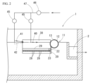
- FIG. 2 is a cross-sectional view taken along line AA in FIG.
- FIG. 3 is an enlarged view of the vicinity of the pipe gap in FIG. 2 .
- 4A is a cross-sectional view of a water injection nozzle
- FIG. 4B is a plan view thereof.
- the following describes a scum removal device 10 according to an embodiment of the present invention.
- FIG. 1 is a plan view of the downstream portion of a sedimentation tank 1 equipped with a scum removal device 10 according to one embodiment of the present invention.
- the sedimentation tank 1 is shown as a primary sedimentation tank provided in a sewage treatment plant.
- This sedimentation tank 1 is configured to receive sewage (hereinafter sometimes referred to as "raw water”, meaning water before purification treatment) received at the sewage treatment plant via a water conduit (not shown).
- raw water meaning water before purification treatment
- the sewage received in the sedimentation tank 1 moves from one side of the sedimentation tank 1 (the left side in the illustrated example) to the other side (the right side in the illustrated example).
- sedimentable substances contained in the sewage settle and are separated.
- the settleable material (sludge) that settles to the bottom of the sedimentation tank 1 is collected by a sludge collector in a pit located at the bottom of one side of the sedimentation tank 1, and then sent to a sludge treatment facility for treatment.
- the raw water contains floating substances in addition to sedimentable substances, and scum, which is a collection of floating substances, is generated on the water surface of the sedimentation tank 1. Therefore, in the sedimentation tank 1, the sedimentable substances are separated as described above, and the scum (see “S” in Figure 3) is removed by the scum removal device 10.
- the treated water from which these precipitated substances and scum S have been removed is received in the overflow trough 2 located on the other side (downstream side) of the sedimentation tank 1.
- the treated water received in the overflow trough 2 is taken out from the overflow trough 2 as shown by the arrow b in Figure 1, and sent to a reaction tank (aeration tank) not shown in the figure for biological treatment.
- the scum removal device 10 is installed downstream of the flow of raw water in the sedimentation tank 1 and upstream of the overflow trough 2.
- This scum removal device 10 is provided with a pipe skimmer 11, which corresponds to the scum intake section of the present invention.
- This pipe gap 11 comprises a pipe material 12 that is arranged to dam the water surface flow, and a rotating mechanism 5 that rotates the pipe material 12.
- this pipe material 12 is arranged horizontally across the width of the settling tank 1, and a slit-shaped opening (scum intake port) 13 is provided along the longitudinal direction in the peripheral wall.
- One longitudinal end of the pipe material 12 penetrates one side wall 3a of the settling tank 1 in a watertight manner and is supported so as to be freely rotatable, while the other longitudinal end is supported so as to be freely rotatable on the other side wall 3b of the settling tank 1.
- the end of the pipe material 12 that penetrates the side wall 3a is positioned within the scum pit 4 provided on the outside of the side wall 3a.
- a rotating mechanism 5 including a motor is provided on the upper surface of the other side wall 3b of the settling tank 1, where the other end of the pipe material 12 is provided.
- This rotating mechanism 5 is configured to rotate the pipe material 12 back and forth around its axis at a predetermined angle.
- the pipe material 12 is supported so that the scum intake port 13, which is provided in the longitudinal direction, is positioned above the water surface as shown in Figures 1 and 2.
- the rotating mechanism 5 rotates as shown by the arrow d in Figure 3 (counterclockwise in Figure 3) so that the water surface is positioned approximately in the middle of the width of the scum intake port 13 (the width along the circumference of the pipe material 12).
- the scum S in front of the pipe material 12 flows toward the scum intake port 13, drops into the pipe material 12 from the scum intake port 13, and is then sent to the scum pit 4 through the inside of the pipe material 12.
- the position of the scum intake port 13 at this time is the scum intake position, and the position where the scum intake port 13 is located above the water surface is the non-intake position.
- the scum discharged into the scum pit 4 is removed from the scum pit 4 as indicated by the arrow c, and sent to a scum treatment facility equipped with a dehydrator (not shown) for treatment.
- the rotation mechanism 5 may be configured to manually rotate the pipe material 12 back and forth without using a motor or the like.
- the pipe material 12 is formed to be longer than the width of the sedimentation tank 1 and is positioned so as to cross the sedimentation tank 1.
- the scum intake port 13 provided in the longitudinal direction of the pipe material 12 is formed to be shorter than the width of the sedimentation tank 1, and both ends in the longitudinal direction are positioned a predetermined distance away from the inner surfaces of the side walls 3a, 3b of the sedimentation tank 1.
- the scum removal device 10 has the pipe gap 11, a front wall plate 20, and a pair of guide plates 30.
- the front wall plate 20 and the guide plates 30 are provided in front of the pipe material 12 (upstream side), i.e., on the side where the raw water approaches the pipe material 12 (the left side of the pipe material 12 in the illustrated example).
- the front wall panel 20 is made of a steel or synthetic resin plate, and when viewed from the direction of the raw water flow (upstream), it has a rectangular shape that is elongated in the width direction of the sedimentation tank 1.
- the length of the long side of the rectangle of the front wall panel 20 is set to be slightly longer than the length of the scum intake port 13 provided in the pipe material 12.
- the short side of the front wall panel 20 is aligned along the depth direction of the sedimentation tank 1. As shown in FIG. 3, the upper end position of the front wall panel 20 is determined to be below the lower end position of the scum intake port 13 when the pipe material 12 rotates and part of the scum intake port 13 is submerged in water (scum intake position). The lower end position of the front wall panel 20 extends below the lower position of the pipe material 12.
- One end of the front wall panel 20 in the longitudinal direction (width direction of the sedimentation tank 1) is fixed to the inner surface of one side wall 3a of the sedimentation tank 1 using a support member 21, and the other end is fixed to the inner surface of the other side wall 3b of the sedimentation tank 1 using a support member 21.
- the rear (downstream) surface of the front wall panel 20 i.e., the surface opposite the direction in which the raw water flows, is close to the pipe material 12 as far as not interfering with the rotation of the pipe material 12, and the position of the upper edge of the front wall panel 20 is lower than the position of the lower end of the scum intake port 13 of the pipe material 12 at the scum intake position, and is carefully positioned.
- the upper edge position of the front wall panel 20 may be at approximately the same height as the lower end position of the scum intake port 13 of the pipe material 12 at the scum intake position.
- a second fluid ejection pipe 22 extending in the width direction of the settling basin is provided using a U-bolt or the like near the bottom edge of the front (upstream) surface of the front wall panel 20, i.e., near the surface near the bottom edge of the front wall panel 20 on the side from which the raw water flows.
- This second fluid ejection pipe 22 is made of a steel or synthetic resin pipe material, and multiple discharge port members 23 are provided in a row at regular intervals along its length.
- the discharge outlet member 23 is made of synthetic resin such as fluororesin, and its external shape is formed in a cup shape (bowl shape, bell shape, etc.) with an opening 24 at the bottom.
- Each discharge outlet member 23 is fixed to the second fluid ejection pipe 22 with its internal space connected to the second fluid ejection pipe 22, and the opening 24 is arranged vertically downward.
- One longitudinal end of the second fluid ejection pipe 22 is closed, and the other end is connected to a flow control valve 25 via a fluid supply pipe 26.
- An opening/closing valve 27 such as a gate valve is provided on the fluid supply pipe 26.
- FIGS 1 to 3 show an example in which a front wall plate 20 is provided, this is not necessarily required, and there are cases in which the front wall plate 20 is not provided. However, providing a front wall plate 20 is preferable, as it creates a wall below the pipe gap 11.
- the second fluid ejection pipe 22 having the discharge outlet member 23 is provided below the pipe gap 11 (gap intake portion).
- the pair of guide plates 30 have the same shape.
- the guide plates 30 are also made of the same steel or synthetic resin plate material as the front wall plate 20.
- the guide plate 30 is rectangular, with its short side positioned along the depth direction within the sedimentation tank 1.
- the width of the guide plate 30 (the dimension along the depth direction of the sedimentation tank 1) is formed to be approximately twice as large as the length of the short side of the front wall plate 20 (the dimension along the depth direction of the sedimentation tank 1).
- the position of the upper edge is higher than the position of the top surface of the scum S, and the position of the lower edge is determined to be approximately equal to the position of the lower edge of the front wall plate 20 (see Figures 2 and 3). Note that there are cases in which the guide plate 30 is not provided.
- a first fluid ejection pipe 29 equipped with a plurality of outlet members 28 is attached using a U-bolt or the like near the bottom edge of the front (upstream) surface of this guide plate 30.
- the first fluid ejection pipe 29 provided on both guide plates 30 is connected to the flow control valve 25 via a fluid supply pipe 26, similar to the second fluid ejection pipe 22 on the front wall plate 20.
- the piping of the first fluid ejection pipe 29 on the side wall 3b side is shown only partway through, and is connected to the piping shown at the top of the figure at the position indicated by the symbol "Q" in Figure 1.
- each guide plate 30 abuts against each end (upper and lower ends in FIG. 1) of the front wall plate 20, and the other longitudinal end (upstream side) is fixed using a support member 32 so as to abut against the inner surfaces of each side wall 3a, 3b of the sedimentation tank 1.
- each guide plate 30 is higher than the top surface of the scum S, and the lower edge is approximately equal to the lower edge of the front wall plate 20.
- each guide plate 30 is attached at an angle ⁇ of approximately 15° to the inner surfaces of each side wall 3a, 3b, and is positioned so that the distance between the pair of guide plates 30 gradually increases as they move upstream.
- the purpose of setting the mounting angle ⁇ on the pair of guide plates 30 is to gradually collect the flowing scum S toward the center of the flow, thereby increasing the concentration of the scum S and obtaining scum S with a low moisture content.
- concentration of scum S it is possible to shorten the length (dimension along the width direction of the settling tank 1) of the scum intake port 13 and front wall plate 20 provided on the pipe material 12, but if the mounting angle ⁇ is large, the guide plate 30 itself will increase the resistance to the flow of scum S. Therefore, the mounting angle ⁇ is appropriately determined depending on the properties of the raw water received in the settling tank 1, the amount of scum S generated, etc.
- a first fluid ejection pipe 29 is provided on each guide plate 30, and water ejection nozzles (above water nozzles) 40, 41, which will be described later, are provided between the guide plates 30, so that the mounting angle ⁇ of the guide plates 30 can be made relatively large.
- Water injection nozzles (above water nozzles) 40, 41 shown in Figures 4A and 4B are provided above the water surface near the scum removal device 10, which is composed of the front wall plate 20 and a pair of guide plates 30, and a water injection nozzle (underwater nozzle) 42 is provided underwater near the water surface.
- multiple above-water nozzles 40 are provided at a predetermined distance from each other in the direction across the sedimentation tank 1 in the area between a pair of guide plates 30.
- Multiple above-water nozzles 41 and submersible nozzles 42 are provided in the same manner as above-water nozzles 40, slightly upstream of the installation position of above-water nozzles 40 (outside the space between the pair of guide plates 30 in the illustrated example).
- Each water injection nozzle 40, 41, 42 is configured with a slit 43 that sprays water approximately parallel to the water surface direction, and a straightening piece 44 that protrudes from the top of the slit 43 and holds the laminar water flow sprayed from the slit 43.
- the water injection nozzle 40 (above water nozzle) located in the area between both guide plates 30 is located approximately at the water surface position, and is installed so that the laminar water flow sprayed from the slit 43 faces the scum removal device 10 side (pipe skimmer 11 side).
- the above-water nozzles 41 and the underwater nozzles 42 are located upstream of the area between the two guide plates 30, and three above-water nozzles 41 are arranged alternately, slightly above the water surface, and three underwater nozzles 42 are arranged slightly below the water surface.
- the above-water nozzles 41 are tilted slightly downward and spray water diagonally from above onto the water surface.
- the underwater nozzles 42 are tilted slightly upward and spray water from underwater onto the water surface.
- the above-water nozzles 41 are shown by solid lines and the underwater nozzles 42 are shown by dashed lines. In the case of a primary sedimentation tank, the underwater nozzle 42 may not be provided.
- These water injection nozzles 40, 41, and 42 can adjust the injection amount appropriately using a flow control valve 45, and are connected to a water supply pipe 47 equipped with an opening/closing valve 46.
- the water injection nozzles 41, 42 can destroy the air bubbles and cause the solid matter to sink and separate by spraying water from above the scum S and from underwater. For this reason, the number and arrangement of the above-water nozzles 41 and underwater nozzles 42 are determined by the properties of the scum S on the water surface, etc.
- the scum S removal operation in the settling tank 1 equipped with the scum removal device 10 configured as described above is carried out as follows.
- the on-off valves 27, 46 are opened simultaneously with or before the rotation of the pipe material 12.
- Water is sprayed onto the scum layer S from water spray nozzles 40, 41, 42 located upstream. This causes air bubbles adhering to the solid matter in the scum layer S to disappear, causing the solid matter floating up due to the air bubbles to settle and separate, and the scum is swept downstream together with the water sprayed downstream.
- the scum layer S passes through the guide plates 30 and is swept away into the scum intake port 13 of the pipe gap 11 (pipe material 12). At this time, compressed air is being ejected as a pressurized fluid from the first fluid ejection pipe 29 on the surface of the guide plate 30, and the bubbling flow reaches the water surface. This causes the scum layer S to flow away from the surface of the guide plate 30, and it is guided to the scum intake port 13 without adhering to the guide plate 30.
- the compressed air continues to be ejected from the first fluid ejection pipe 29 near the guide plate 30 even after the scum intake has started, as this prevents scum from adhering to the guide plate 30 and also removes the scum from the surface of the guide plate 30, facilitating a smooth flow to the scum intake port 13.
- the water flow ejected from the water injection nozzles 40 arranged in the area between the guide plates 30 promotes the flow of scum S, enabling the scum S to be quickly discharged toward the pipe gap 11 (pipe material 12).
- the scum S that is captured in the pipe gap 11 (pipe material 12) is discharged into the scum pit 4 and sent to a scum treatment facility for treatment.
- the scum removal device 10 configured as above includes a front wall plate 20 equipped with a second fluid ejection pipe 22, a pair of guide plates 30 equipped with a first fluid ejection pipe 29, and water ejection nozzles 40, 41, 42, so that scum can be discharged in a shorter time, and the amount of water that flows into the pipe gap together with the scum is reduced, allowing the scum to be removed in a shorter time.
- scum can be removed by operating the device for about 7 to 10 minutes once a week. This reduces the amount of water returned upstream from the pipe gap, and the amount of electricity required for scum removal and water return can be reduced, resulting in energy savings.
- the scum removal device 10 configured as described above has the excellent feature of being able to greatly contribute to greater energy savings and reduced burden on the natural environment.
- the scum removal device 10 configured as above has the advantage that the main components, the second fluid ejection pipe 22, the front wall panel 20 equipped with the first fluid ejection pipe 29, and the pair of guide plates 30, can be prefabricated in a factory, and can be easily applied to existing settling tanks.
- the second fluid ejection pipe 22 and the first fluid ejection pipe 29 are provided with the ejection outlet member 23, but the fluid ejection pipe itself may have a small hole without providing the ejection outlet member 23.
- the ejection outlet member 23 is provided, the upward flow of the compressed air can be regulated.
- the fluid ejected from the second fluid ejection pipe 22 and the first fluid ejection pipe 29 is compressed air in the above embodiment, but the same effect can be obtained by using a water flow or pressurized water containing air bubbles.
- the scum intake section is a pipe skimmer type, but it may be a trough type in which the inlet weir is moved up and down to take in the scum.
- the scum removal device 10 is applied to a primary settling tank, it can also be applied to a final settling tank.
- the water injection nozzles 40, 41 can be omitted to prevent the scum from becoming pin flocked (fine).
- Scum can be removed in a shorter time, and the amount of water that is entrained with the scum is reduced, which contributes to reducing electricity consumption, etc. Furthermore, the quality of the treated water from which the scum has been removed is improved, which has the extremely advantageous effect of reducing the burden on the environment when it is released into the natural environment. Moreover, it can be easily applied to existing settling tanks.
Landscapes
- Chemical & Material Sciences (AREA)
- Analytical Chemistry (AREA)
- Life Sciences & Earth Sciences (AREA)
- Hydrology & Water Resources (AREA)
- Engineering & Computer Science (AREA)
- Environmental & Geological Engineering (AREA)
- Water Supply & Treatment (AREA)
- Organic Chemistry (AREA)
- Removal Of Floating Material (AREA)
Priority Applications (3)
| Application Number | Priority Date | Filing Date | Title |
|---|---|---|---|
| AU2024345198A AU2024345198A1 (en) | 2023-09-19 | 2024-08-22 | Scum removing device |
| JP2025504468A JP7769442B2 (ja) | 2023-09-19 | 2024-08-22 | スカム除去装置 |
| MX2026002731A MX2026002731A (es) | 2023-09-19 | 2026-03-06 | Dispositivo de eliminacion de nata |
Applications Claiming Priority (2)
| Application Number | Priority Date | Filing Date | Title |
|---|---|---|---|
| JP2023-151070 | 2023-09-19 | ||
| JP2023151070 | 2023-09-19 |
Publications (1)
| Publication Number | Publication Date |
|---|---|
| WO2025062933A1 true WO2025062933A1 (ja) | 2025-03-27 |
Family
ID=95072716
Family Applications (1)
| Application Number | Title | Priority Date | Filing Date |
|---|---|---|---|
| PCT/JP2024/029790 Pending WO2025062933A1 (ja) | 2023-09-19 | 2024-08-22 | スカム除去装置 |
Country Status (4)
| Country | Link |
|---|---|
| JP (1) | JP7769442B2 (https=) |
| AU (1) | AU2024345198A1 (https=) |
| MX (1) | MX2026002731A (https=) |
| WO (1) | WO2025062933A1 (https=) |
Citations (4)
| Publication number | Priority date | Publication date | Assignee | Title |
|---|---|---|---|---|
| JP2003170163A (ja) * | 2001-09-25 | 2003-06-17 | Asahi Tec Corp | スカム破砕装置 |
| JP2011088048A (ja) * | 2009-10-21 | 2011-05-06 | Utsunomiya Kogyo Kk | スカム除去装置 |
| JP2013154348A (ja) * | 2013-04-10 | 2013-08-15 | Utsunomiya Kogyo Kk | スカム除去装置 |
| WO2022044564A1 (ja) * | 2020-08-27 | 2022-03-03 | 宇都宮工業株式会社 | 圧縮空気噴出機構及びそれを用いた導水渠並びに沈殿池 |
-
2024
- 2024-08-22 JP JP2025504468A patent/JP7769442B2/ja active Active
- 2024-08-22 WO PCT/JP2024/029790 patent/WO2025062933A1/ja active Pending
- 2024-08-22 AU AU2024345198A patent/AU2024345198A1/en active Pending
-
2026
- 2026-03-06 MX MX2026002731A patent/MX2026002731A/es unknown
Patent Citations (4)
| Publication number | Priority date | Publication date | Assignee | Title |
|---|---|---|---|---|
| JP2003170163A (ja) * | 2001-09-25 | 2003-06-17 | Asahi Tec Corp | スカム破砕装置 |
| JP2011088048A (ja) * | 2009-10-21 | 2011-05-06 | Utsunomiya Kogyo Kk | スカム除去装置 |
| JP2013154348A (ja) * | 2013-04-10 | 2013-08-15 | Utsunomiya Kogyo Kk | スカム除去装置 |
| WO2022044564A1 (ja) * | 2020-08-27 | 2022-03-03 | 宇都宮工業株式会社 | 圧縮空気噴出機構及びそれを用いた導水渠並びに沈殿池 |
Also Published As
| Publication number | Publication date |
|---|---|
| JPWO2025062933A1 (https=) | 2025-03-27 |
| MX2026002731A (es) | 2026-04-01 |
| AU2024345198A1 (en) | 2025-09-25 |
| JP7769442B2 (ja) | 2025-11-13 |
Similar Documents
| Publication | Publication Date | Title |
|---|---|---|
| JP5249237B2 (ja) | スカム除去装置 | |
| JP5443122B2 (ja) | スカム除去装置 | |
| JP4990856B2 (ja) | スカム除去装置 | |
| JP7112794B1 (ja) | 導水渠並びに沈殿池 | |
| JP5443260B2 (ja) | スカム除去装置用噴出ノズル | |
| JP7769442B2 (ja) | スカム除去装置 | |
| JP3943551B2 (ja) | スカム除去装置 | |
| JP2011218306A (ja) | スカム除去装置およびスカム除去方法 | |
| JP5728723B2 (ja) | 揚砂方法 | |
| KR101166327B1 (ko) | 폐수처리용 다열주입식 가압부상조 | |
| JP5443261B2 (ja) | スカム除去装置 | |
| JP5842203B2 (ja) | 揚砂方法 | |
| JP7668076B1 (ja) | 下水処理場におけるスカム除去システム | |
| JP7112795B1 (ja) | 導水渠システム | |
| JP5457967B2 (ja) | スカム除去装置用噴射ノズル | |
| JP5891197B2 (ja) | スカム除去装置 | |
| JP7748145B2 (ja) | スカム剥離装置及び導水渠並びに沈殿池 | |
| JP2012040565A (ja) | 揚砂方法 | |
| JP5441188B2 (ja) | 揚砂方法 | |
| JP3818550B2 (ja) | スカム沈降除去装置 | |
| WO2021033781A1 (ja) | スカム除去装置用噴出ノズル | |
| JPS6337118Y2 (https=) | ||
| CN2749877Y (zh) | 气浮池水射式水力自动排渣装置 | |
| JP2004024965A (ja) | 生物反応槽におけるスカム排出方法及びその装置 | |
| JP2015142920A (ja) | 揚砂方法 |
Legal Events
| Date | Code | Title | Description |
|---|---|---|---|
| ENP | Entry into the national phase |
Ref document number: 2025504468 Country of ref document: JP Kind code of ref document: A |
|
| WWE | Wipo information: entry into national phase |
Ref document number: 2025504468 Country of ref document: JP |
|
| 121 | Ep: the epo has been informed by wipo that ep was designated in this application |
Ref document number: 24868013 Country of ref document: EP Kind code of ref document: A1 |
|
| WWE | Wipo information: entry into national phase |
Ref document number: AU2024345198 Country of ref document: AU |
|
| ENP | Entry into the national phase |
Ref document number: 2024345198 Country of ref document: AU Date of ref document: 20240822 Kind code of ref document: A |
|
| WWE | Wipo information: entry into national phase |
Ref document number: 2601001257 Country of ref document: TH |
|
| REG | Reference to national code |
Ref country code: BR Ref legal event code: B01A Ref document number: 112026006389 Country of ref document: BR |