WO2025062844A1 - 検査システム、検査方法、およびプログラム - Google Patents
検査システム、検査方法、およびプログラム Download PDFInfo
- Publication number
- WO2025062844A1 WO2025062844A1 PCT/JP2024/027355 JP2024027355W WO2025062844A1 WO 2025062844 A1 WO2025062844 A1 WO 2025062844A1 JP 2024027355 W JP2024027355 W JP 2024027355W WO 2025062844 A1 WO2025062844 A1 WO 2025062844A1
- Authority
- WO
- WIPO (PCT)
- Prior art keywords
- rotation
- container
- axis
- vial
- rotation axis
- Prior art date
- Legal status (The legal status is an assumption and is not a legal conclusion. Google has not performed a legal analysis and makes no representation as to the accuracy of the status listed.)
- Pending
Links
Images



Classifications
-
- G—PHYSICS
- G01—MEASURING; TESTING
- G01N—INVESTIGATING OR ANALYSING MATERIALS BY DETERMINING THEIR CHEMICAL OR PHYSICAL PROPERTIES
- G01N21/00—Investigating or analysing materials by the use of optical means, i.e. using sub-millimetre waves, infrared, visible or ultraviolet light
- G01N21/84—Systems specially adapted for particular applications
- G01N21/88—Investigating the presence of flaws or contamination
- G01N21/90—Investigating the presence of flaws or contamination in a container or its contents
Definitions
- This disclosure relates to an inspection system, an inspection method, and a program.
- Patent Document 1 discloses an inspection method that includes a step of rotating a container (e.g., a syringe) by 180 degrees or more around an axis perpendicular to the central axis of the container, and then rotating the container around the central axis. This inspection method makes it possible to obtain image data for accurately detecting foreign objects.
- a container e.g., a syringe
- one of the objectives of the present disclosure is to provide an inspection system, an inspection method, and a program that improve the accuracy of detecting foreign objects in containers filled with liquid.
- the inspection system includes a rotation control unit that performs control to rotate a container filled with liquid around a first rotation axis, which is the central axis of the container, while rotating the container around a second rotation axis perpendicular to the first rotation axis in a direction that increases the inclination of the first rotation axis with respect to the vertical axis.
- the inspection method rotates a container filled with liquid around a first axis of rotation, which is the central axis of the container, while rotating the container around a second axis of rotation perpendicular to the first axis of rotation in a direction that increases the inclination of the first axis of rotation relative to the vertical axis.
- the program according to the third aspect of the present disclosure causes a computer to execute control to rotate a container filled with liquid around a first axis of rotation, which is the central axis of the container, while rotating the container around a second axis of rotation perpendicular to the first axis of rotation in a direction that increases the inclination of the first axis of rotation relative to the vertical axis.
- This disclosure provides an inspection system, inspection method, and program that improves the accuracy of detecting foreign objects in containers filled with liquid.
- FIG. 1 is an explanatory diagram for explaining an overview of an inspection method according to a study example.
- FIG. 11 is an explanatory diagram for explaining a problem with the inspection method according to the study example.
- 1 is a block diagram showing a configuration of an inspection system according to the present disclosure.
- 1 is a flowchart showing the flow of an inspection method according to the present disclosure.
- FIG. 1 is a configuration diagram of an inspection system according to the present disclosure.
- FIG. 1 is a block diagram illustrating an example of an information processing device according to the present disclosure.
- 1 is a flowchart showing the flow of an inspection method according to the present disclosure.
- FIG. 13 is an explanatory diagram illustrating the movement of a vial according to the present disclosure.
- FIG. 2 is a block diagram illustrating a hardware configuration of an information processing device according to the present disclosure.
- FIG. 1 is a diagram for explaining an overview of the inspection method according to the studied example.
- the left figure shows the bottom of a container 1 (e.g., a vial) that has been upside-down.
- the right figure shows the side of the container 1 that has been upside-down.
- the container 1 is filled with liquid 3.
- a foreign object 2 is attached to the inner wall of the bottle body of the container 1.
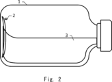
- FIG. 2 is a diagram explaining the problem with the inspection method according to the examined example.
- the inventor discovered that there is a possibility that foreign object 2 may adhere to the bottom surface of container 1 when container 1 is turned sideways.
- foreign object 2 cannot be clearly observed due to interference between the light from foreign object 2 and the light from the bottom surface or the liquid surface of container 1, or due to obstruction by unevenness on the bottom surface, making it difficult to detect foreign object 2.
- FIG. 3 is a block diagram showing a configuration of an inspection system 10 according to the present disclosure.
- the inspection system 10 includes a rotation control unit 11.
- the inspection system 10 may further include a first rotation drive mechanism (not shown) and a second rotation drive mechanism (not shown).
- the first rotation drive mechanism rotates the container around a first rotation axis, which is the central axis of the container, according to the control of the rotation control unit 11.
- the second rotation drive mechanism rotates the container around a second rotation axis perpendicular to the first rotation axis, according to the control of the rotation control unit 11.
- the first rotation drive mechanism and the second drive mechanism may include a motor.
- the inspection system 10 includes an information processing device (not shown) that includes a rotation control unit 11.
- the information processing device may be a computer device that operates by a processor executing a program stored in a memory.
- the information processing device may be composed of multiple computer devices.
- a container e.g., a vial, an ampoule, a syringe, a plastic bottle
- a liquid e.g., a medicine (including protein preparations), drinking water, etc.
- the first rotation axis passes through the center of the bottom surface of the container and the center of the top surface of the container.
- the container may be formed in a cylindrical shape centered on the first rotation axis.
- the rotation control unit 11 performs control to rotate the container around the first rotation axis while rotating the container around the second rotation axis in a direction in which the inclination of the first rotation axis with respect to the vertical axis increases. Specifically, the rotation control unit 11 generates a first control signal and a second control signal for performing the above control, and outputs the first control signal and the second control signal to the first rotation drive mechanism and the second rotation drive mechanism, respectively.
- the rotation of the container around the first rotation axis (also called the first rotation) and the rotation of the container around the second rotation axis (also called the second rotation) may be performed simultaneously. Alternatively, the first rotation and the second rotation may be performed multiple times in this order or in the reverse order. In this case, the first rotation and the second rotation are performed intermittently.
- step S1 while rotating the container about a first rotation axis, the container is rotated about a second rotation axis in a direction in which the inclination of the first rotation axis with respect to the vertical axis increases (step S1).
- the inspection system 10 may obtain an image of the side surface of the container, and detect any foreign objects present in the container based on the image.
- the inspection system 10 rotates the container around the first rotation axis while rotating the container around the second rotation axis in a direction that increases the inclination of the first rotation axis with respect to the vertical axis.
- the inspection system 10 can prevent foreign matter from adhering to the bottom surface of the container and improve the accuracy of detecting foreign matter in the container.
- FIG. 5 is a configuration diagram of an inspection system 100 according to the present disclosure.
- the inspection system 100 is a specific example of the inspection system 10.
- the inspection system 100 is a system that inspects a filled vial 110.
- the filled vial 110 is an example of the above-mentioned container.
- the inspection system 100 includes, as main components, a gripping and rotating device 200, a lighting device 300, a camera device 400, an information processing device 500, and a display device 600.
- the filled vial (hereinafter simply referred to as a vial) 110 is, for example, a bottle in which a drug solution is filled, the opening is sealed with a rubber stopper, and an aluminum cap is placed over the rubber stopper after the drug solution is filled in order to store the drug solution in a sterile state.
- a cap (such as a flip cap) in which an aluminum seal and a plastic cap are integrated may also be used.
- the rubber stopper and the aluminum and plastic caps form the lid of the vial 110.
- the amount of liquid filled in the vial 110 in this example is approximately half the capacity of the vial 110. That is, the liquid level height R of the vial 110 in this example is approximately the center of the bottle body.
- the vials to which the present invention can be applied are not limited to the above.
- the amount of liquid filled in the vial 110 does not need to be approximately half the capacity of the vial 110, and may be more than half or less than half.
- the vial 110 may have various defects. For example, there is a possibility that a foreign object is mixed in the vial 110. Examples of foreign objects include glass fragments, metal fragments, rubber fragments, hair, fiber fragments, soot, and the like.
- the vial 110 may also have cracks, scratches, dirt, poor seaming, or insufficient medicine.
- the inspection system 100 is a system that inspects the presence or absence of various defects that may occur in the vial 110.
- the inspection system 100 inspects for foreign objects attached to the bottle body, scratches on the bottle body, objects attached to the back of the lid, and scratches on the bottom surface.
- the items inspected by the inspection system 100 are not limited to the above. Items other than the above inspection items, such as foreign objects floating in the filled liquid, foreign objects settling on the bottom surface, insufficient medicine (insufficient filling), foreign objects floating on the liquid surface, poor seaming, and scratches on the bottle head, may also be inspected.
- the vial 110 is composed of, from top to bottom in an upright position, a seam, a bottle head (container head), a cone-shaped bottle shoulder (container shoulder), a cylindrical bottle body (container body), and a bottle bottom that closes the bottle body.
- Foreign matter attached to the bottle body is foreign matter attached to the inner wall surface or outer wall side surface of the bottle body of the vial 110.
- a representative example of foreign matter attached to the bottle body is fiber fragments. The size of the fiber fragments is about several tens of ⁇ m in diameter, and the length is about several hundred ⁇ m to several mm. Damage to the bottle body is cracks, scratches, dirt, etc. on the bottle body of the vial 110.
- Matter attached to the back of the lid is foreign matter attached to the back side of the lid of the vial 110 (the back side of the rubber stopper). Damage to the bottom is cracks, scratches, dirt, etc. on the bottle bottom of the vial 110. The size of the bottle body scratches and bottom scratches to be detected is on the order of mm. This is because fine scratches are generally not considered a problem.
- the gripping and rotating device 200 is a device that can rotate the vial 110 while gripping it.
- the gripping and rotating device 200 has two mutually perpendicular rotation axes (rotation axis A and rotation axis B), and can rotate the gripped vial 110 around rotation axis A and rotation axis B.
- Rotation axis A corresponds to the above-mentioned first rotation axis
- rotation axis B corresponds to the above-mentioned second rotation axis.
- the gripping and rotating device 200 includes a flat plate member 201, an upper arm 202 connected to the upper end of the flat plate member 201, and a lower arm 203 connected to the lower end of the flat plate member 201.
- a lower gripping part 204 is connected to the end of the lower arm 203 opposite to the end to which the flat plate member 201 is connected.
- the lower gripping portion 204 functions as a base on which the vial 110 is placed.
- a rotatable plate 205 is attached to the upper surface of the lower gripping portion 204.
- a chuck mechanism 206 having a chuck finger 211 for chucking the vial 110 is provided at the end of the upper arm 202 opposite to the end to which the flat plate member 201 is connected.
- the chuck mechanism 206 can be configured as a parallel opening and closing type air chuck, but is not limited to this.
- the chuck finger 211 is freely rotatable around the rotation axis A and can be raised and lowered along the rotation axis A.
- the chuck mechanism 206 closes, opens, rotates, and raises and lowers the chuck finger 211 according to commands sent from the information processing device 500.
- the vial 110 When the vial 110 is placed on the plate 205 in an upright position and the chuck finger 211 is lowered to chuck the bottle head of the vial 110, the vial 110 is gripped by the gripping and rotating device 200 so that the central axis of the vial 110 (the axis passing through the center of the head and bottom, also called the upright central axis) coincides with the rotation axis A.
- the vial 110 rotates around the rotation axis A.
- a rotation angle detector 209 such as an encoder, provided on the upper arm 202 detects the rotation angle of the chuck fingers 211, and therefore the rotation angle of the vial 110 chucked by the chuck fingers 211 about the rotation axis A.
- the rotation angle detector 209 is configured to output the rotation angle to the information processing device 500.
- the lighting device 300 is a surface light source that illuminates the bottle body of the vial 110 chucked by the chuck mechanism 206 of the gripping and rotating device 200 from a direction perpendicular to the rotation axis A, and is attached to the flat plate-shaped member 201.
- the lighting device 300 is installed on the opposite side of the vial 110 from the camera device 400.
- the flat plate member 201 is supported by a rotating shaft 208 that is rotated by a motor 207.
- the motor 207 is fixed by a support member (not shown).
- the rotating shaft 208 is rotated by the motor 207, the flat plate member 201 rotates.
- all elements directly or indirectly connected or attached to the flat plate member 201 i.e., the upper arm 202, the lower arm 203, the lower gripping portion 204, the chuck finger 211, the chuck mechanism 206, the plate 205, the lighting device 300, the rotation angle detector 209, and the rotation angle detector 210, rotate. Therefore, the vial 110 placed on the plate 205 and chucked by the chuck mechanism 206 also rotates around the rotation axis B.
- a rotation angle detector 210 such as an encoder, provided on the flat plate member 201 is configured to detect the rotation angle of the rotating shaft 208, and therefore the rotation angle of the vial 110 chucked by the chuck finger 211 about the rotation axis B, and output it to the information processing device 500.
- the camera device 400 has a wide-angle lens and is a high-speed camera that continuously captures images of the vial body of the vial 110 at a predetermined frame rate (100 fps or more) from a predetermined position on the opposite side of the vial 110 from the side on which the lighting device 300 is installed.
- the camera device 400 may have a telecentric lens instead of a wide-angle lens.
- the optical axis of the camera device 400 is parallel to the rotation axis B.
- the focus value of the camera device 400 is adjusted, for example, so that scratches on the outer wall of the vial body close to the camera device 400 and foreign objects attached to the inner wall can be clearly captured.
- the camera device 400 includes, for example, a color camera equipped with a CCD (Charge-Coupled Device) image sensor or a CMOS (Complementary MOS) image sensor with a pixel capacity of several million pixels. Alternatively, the camera device 400 may be configured to include a black-and-white camera.
- the camera device 400 is connected to the information processing device 500 by wire or wirelessly.
- the camera device 400 is configured to transmit time-series images obtained by photographing to the information processing device 500 together with information indicating the photographing time, etc.
- the display device 600 is a display device such as an LCD (Liquid Crystal Display).
- the display device 600 is connected to the information processing device 500 by wire or wirelessly.
- the display device 600 is configured to display the results of an inspection of the vial 110 performed by the information processing device 500.
- the information processing device 500 is a device that performs image processing on the time series images captured by the camera device 400, and inspects the vial 110 for foreign objects.
- the information processing device 500 is connected to the gripping and rotating device 200, the camera device 400, and the display device 600 by wire or wirelessly.
- FIG. 6 is a block diagram showing an example of an information processing device 500.
- the information processing device 500 includes a communication I/F unit 510, an operation input unit 520, a storage unit 530, and an arithmetic processing unit 540.
- the communication I/F unit 510 is composed of a data communication circuit, and is configured to perform data communication via wire or wirelessly between the gripping and rotating device 200, the lighting device 300, the camera device 400, the display device 600, and other external devices (not shown).
- the operation input unit 520 is composed of operation input devices such as a keyboard and a mouse, and is configured to detect the operation of the operator and output it to the calculation processing unit 540.
- the storage unit 530 is composed of one or more storage devices of one or more types, such as a hard disk or memory, and is configured to store processing information and programs 531 required for various processes in the arithmetic processing unit 540.
- the programs 531 are programs that are loaded into the arithmetic processing unit 540 and executed to realize various processing units, and are loaded in advance from an external device or recording medium (not shown) via a data input/output function such as the communication I/F unit 510, and stored in the storage unit 530.
- the calculation processing unit 540 has a processor such as a CPU (Central Processing Unit) and its peripheral circuits, and is configured to read and execute a program 531 from the storage unit 530, thereby implementing various processing units through cooperation between the above hardware and the program 531.
- the main processing units implemented by the calculation processing unit 540 include a gripping/rotation control unit 541, an acquisition unit 542, a detection unit 543, and a display control unit 544.
- the gripping/rotation control unit 541 is a specific example of the rotation control unit 11 described above.
- the gripping/rotation control unit 541 is configured to control the gripping/rotating device 200.
- the gripping/rotation control unit 541 controls operations such as lowering, closing, rotating, opening, and raising of the chuck finger 211 by transmitting and receiving signals to and from the chuck mechanism 206 of the gripping/rotating device 200 via the communication I/F unit 510. In this way, the gripping/rotation control unit 541 controls the rotation of the vial 110 gripped by the gripping/rotating device 200 about the rotation axis A.
- the gripping/rotation control unit 541 also controls the rotation of the vial 110 gripped by the gripping/rotating device 200 about the rotation axis B by transmitting and receiving signals to and from the motor 207 via the communication I/F unit 510.
- the gripping and rotation control unit 541 also monitors the rotation angles around the rotation axis A and the rotation axis B of the vial 110 gripped by the gripping and rotating device 200 by transmitting and receiving signals to and from the rotation angle detectors 209 and 210 via the communication I/F unit 510.
- the gripping and rotation control unit 541 controls the rotation of the vial 110 around the rotation axis A while controlling the rotation of the vial 110 around the rotation axis B so that the rotation axis A approximately coincides with the horizontal axis.
- the inclination of the rotation axis A with respect to the vertical axis changes from 0° to 90°.
- the "inclination of the rotation axis A with respect to the vertical axis” may correspond to the absolute value of the rotation angle around the rotation axis B.
- the angle of rotation around the axis of rotation B may be expressed, for example, as a positive value (e.g., 0 to +90°) for a clockwise rotation angle and a negative value (e.g., 0 to -90°) for a counterclockwise rotation angle.
- the acquisition unit 542 is configured to control the lighting device 300 and the camera device 400.
- the acquisition unit 542 controls the lighting device 300 to be turned on and off by transmitting and receiving signals to and from the lighting device 300 through the communication I/F unit 510.
- the acquisition unit 542 also controls the photographing of the vial 110 held by the gripping and rotating device 200 by transmitting and receiving signals to and from the camera device 400 through the communication I/F unit 510, and acquires time-series images obtained by photographing.
- the acquisition unit 542 also stores in the memory unit 530 image information (not shown) including the images acquired from the camera device 400 and information on the rotation angles of the vial 110 around the rotation axes A and B monitored by the rotation angle detectors 209 and 210.
- the detection unit 543 is configured to inspect the presence or absence of foreign matter in the vial 110 based on the image information acquired by the acquisition unit 542.
- the detection unit 543 is also configured to store information representing the inspection results in the storage unit 530.
- the display control unit 544 is configured to output information representing the test results to the display device 600.
- FIG. 7 is a flow chart showing an example of the flow of the inspection method according to the present disclosure.
- the inspection system 100 performs the process shown in FIG. 7 for each vial 110 to be inspected. Dust and other particles that may adhere to the outside of the vial 110 to be inspected are blown away with air immediately before inspection.
- the gripping and rotating control unit 541 When starting to rotate the vial 110 around rotation axis A, the gripping and rotating control unit 541 issues a rotation start command to the chuck mechanism 206 specifying the rotation direction, and when ending the rotation, issues a rotation end command to the chuck mechanism 206. Furthermore, when rotating vial 110 around rotation axis B, gripping/rotation control unit 541 issues a rotation start command specifying the rotation direction to motor 207, and when terminating the rotation, issues a rotation end command to motor 207. During rotation, gripping/rotation control unit 541 also monitors the rotation angles around rotation axis A and rotation axis B detected by rotation angle detector 209 and rotation angle detector 210.
- step S23 when the camera device 400 starts photographing the vial 110, the acquisition unit 542 issues a turn-on command to the lighting device 300 and an image capture start command to the camera device 400, and when the image capture ends, it issues an image capture end command to the lighting device 300 and an image capture end command to the camera device 400.
- the lighting device 300 may be always on.
- the acquisition unit 542 may also issue a command to control the zoom and/or focus to the camera device 400 so that the zoom amount and focus value of the camera device 400 are changed during image capture. Note that, when rotation and image capture are started simultaneously in step S23, the gripping/rotation control unit 541 and the acquisition unit 542 are configured to operate in synchronization.
- the gripping/rotation control unit 541 issues a rotation start command to the chuck mechanism 206.
- the acquisition unit 542 then issues a command to start shooting to the camera device 400 in synchronization with the rotation start command.
- step S23 the acquisition unit 542 receives time-series images sent from the camera device 400 while the camera device 400 is taking pictures, together with information indicating the time of taking the pictures.
- the acquisition unit 542 also receives information on the monitored rotation angle around the rotation axis A from the rotation angle detector 209 through the gripping and rotation control unit 541.
- the acquisition unit 542 then associates the time-series images received from the camera device 400 with the shooting time and the rotation angle of the rotation axis A and stores them in the storage unit 530.
- the acquisition unit 542 uses the monitored information on the rotation angle around the rotation axis A. However, since the rotating table is set in advance and known, processing may be performed assuming that the rotation always starts and ends at a fixed time.
- the acquisition unit 542 automatically determines the programmed rotation angle of the rotation axis A from the time information at the start of operation of the information processing device 500.
- the acquisition unit 542 then associates the rotation angle with the time-series images and stores them in the storage unit 530.
- the detection unit 543 of the inspection system 100 detects foreign matter in the vial 110 based on the acquired information, and stores information representing the inspection results in the memory unit 530 (step S24).
- the display control unit 544 of the inspection system 100 may display the information representing the inspection results on the display device 600 and/or transmit it to an external device (not shown) via the communication I/F unit 510.
- the inspection system 100 returns the posture of the vial 110 after the inspection to an upright posture, and transports the vial 110 (step S25).
- the gripping and rotation control unit 541 issues a rotation start command to the motor 207.
- the gripping and rotation control unit 541 controls the chuck mechanism 206 to release the chuck finger 211 and then raise it.
- the gripping and rotation control unit 541 uses a robot arm or human hands (not shown) to move the vial 110 on the plate 205 of the gripping and rotation device 200 to a storage location according to the inspection result. For example, a vial 110 in which a foreign object is detected is isolated.
- step S24 foreign object detection by image analysis
- the rotation and photographing of the vial 110 (step S23) and the detection of foreign objects by image analysis (step S24) may be performed simultaneously (sequential processing).
- the upper diagram shows the vial 110 in an upright position.
- the foreign object 2 floats on the surface of the liquid 3. If the specific gravity of the foreign object 2 is smaller than that of the liquid 3, or if the foreign object 2 has no affinity for the liquid 3, the foreign object 2 floats on the surface of the liquid 3.
- the middle diagram shows the vial 110 rotating around the rotation axis A while rotating around the rotation axis B.
- the solid arrow indicates the movement direction of the foreign object 2. Since the vial 110 rotates around the rotation axis A, the foreign object 2 adheres to the inner wall of the bottle body and passes through the boundary between inside and outside the liquid according to the rotation of the rotation axis A.
- the lower diagram shows the vial 110 in a sideways position.
- the foreign object 2 adheres to the inner wall of the bottle body.
- the imaging area 4 surrounded by the dotted line represents the imaging area of the camera device 400.
- the imaging area 4 is, for example, a portion of the bottle body above the liquid surface (e.g., the upper half). Since the background image is uniform, the inspection system 100 can easily detect the foreign object 2. A shadow in the captured image may be detected as the foreign object 2 or a scratch.
- the gripping/rotation control unit 541 may rotate the vial 110 by 720° or more around the rotation axis A. Alternatively, the gripping/rotation control unit 541 may rotate the vial 110 by 360° in one direction around the rotation axis A, and then rotate it by 360° in the opposite direction. Then, the detection unit 543 extracts images of the imaging area 4 captured when the rotation angle around the rotation axis A is the same, and detects image areas in which the difference is equal to or greater than a threshold or the brightness is equal to or greater than a threshold as candidates for foreign objects. The detection unit 543 may also determine whether or not an object is a foreign object based on image features around the object.
- the object to be inspected is, for example, a transparent fiber present in a vial 110 filled with a low-viscosity liquid. Such foreign matter is often found floating on the outer periphery of the liquid surface or adhering to the inner wall of the vial 110's body.
- the inspection system 100 turns the vial 110 sideways and adheres any foreign matter floating on the liquid surface to the inner wall of the vial's body.
- the inspection system 100 then observes the foreign matter that has adhered to the inner wall of the bottle body. Therefore, the inspection system 100 can also observe foreign matter that was originally attached to the inner wall of the bottle body. Furthermore, even when performing transmitted light photography, the effect of wetting improves the visibility of foreign matter.
- the inspection system 100 rotates the vial 110 around the rotation axis A even while changing the position of the vial 110, the foreign object 2 adheres to the inner wall of the bottle body. Since the foreign object 2 attached to the bottle body does not move toward the bottom of the bottle, the amount of movement of the foreign object 2 toward the bottom of the bottle is reduced.
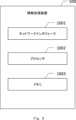
- FIG. 9 is a block diagram showing an example of the configuration of an information processing device including the rotation control unit 11 described in the first embodiment and the information processing device 500 described in the second embodiment (hereinafter also referred to as the information processing device 500, etc.).
- the information processing device 500, etc. includes a network interface 1001, a processor 1002, and a memory 1003.
- the network interface 1001 may be used to communicate with a network node.
- the network interface 1001 may include, for example, a network interface card (NIC) that complies with the IEEE 802.3 series. IEEE stands for Institute of Electrical and Electronics Engineers.
- the processor 1002 reads out and executes software (computer programs) from the memory 1003 to perform the processing of the information processing device 500 and the like described using the flowcharts in the above-mentioned embodiment.
- the processor 1002 may be, for example, a microprocessor, an MPU, or a CPU.
- the processor 1002 may include multiple processors.
- Memory 1003 is composed of a combination of volatile memory and non-volatile memory. Memory 1003 may include storage located away from processor 1002. In this case, processor 1002 may access memory 1003 via an I/O (Input/Output) interface (not shown).
- I/O Input/Output
- the memory 1003 is used to store a group of software modules.
- the processor 1002 reads out and executes these software modules from the memory 1003, thereby performing the processing of the information processing device 500 and the like described in the above embodiment.
- each of the processors of the information processing device 500 in the above-mentioned embodiment executes one or more programs including a set of instructions for causing a computer to execute the algorithm explained using the drawing.
- the program includes instructions (or software code) that, when loaded into a computer, cause the computer to perform one or more functions described in the embodiments.
- the program may be stored on a non-transitory computer-readable medium or a tangible storage medium.
- computer-readable media or tangible storage media include random-access memory (RAM), read-only memory (ROM), flash memory, solid-state drive (SSD) or other memory technology, CD-ROM, digital versatile disc (DVD), Blu-ray (registered trademark) disk or other optical disk storage, magnetic cassette, magnetic tape, magnetic disk storage or other magnetic storage device.
- the program may be transmitted on a temporary computer-readable medium or communication medium.
- the temporary computer-readable medium or communication medium includes electrical, optical, acoustic, or other forms of propagating signals.
- the present invention is not limited to the above embodiment, and can be modified as appropriate without departing from the spirit of the invention.
- a vial was used as the inspection object, but bottles and containers other than vials can also be inspected as long as they are transparent or translucent containers filled with liquid such as drinking water.
- An inspection system comprising a rotation control unit that performs control to rotate a container filled with liquid around a first rotation axis, which is the central axis of the container, while rotating the container around a second rotation axis perpendicular to the first rotation axis in a direction that increases the inclination of the first rotation axis with respect to a vertical axis.
- Appendix 2 2. The inspection system of claim 1, wherein a first rotation of the container about the first axis of rotation and a second rotation of the container about the second axis of rotation are performed simultaneously.
- Appendix 3 2.
- Appendix 4 an acquisition unit that acquires an image of a side surface of the container after the control by the rotation control unit; and a detection unit that detects a foreign object present in the container based on the captured image.
- Appendix 5 5.
- An inspection method comprising: rotating a container filled with liquid around a first rotation axis, which is the central axis of the container; and rotating the container around a second rotation axis perpendicular to the first rotation axis in a direction that increases the inclination of the first rotation axis with respect to a vertical axis.
- Appendix 10 A program that causes a computer to execute control to rotate a container filled with liquid around a first rotation axis, which is the central axis of the container, while rotating the container around a second rotation axis perpendicular to the first rotation axis in a direction that increases the inclination of the first rotation axis with respect to a vertical axis.
- Supplementary Notes 2 to 8 Some or all of the elements (e.g., configurations and functions) described in Supplementary Notes 2 to 8 that are dependent on Supplementary Note 1 may also be dependent on Supplementary Notes 9 and 10 in the same dependent relationship as Supplementary Notes 2 to 8. Some or all of the elements described in any of the supplementary notes may be applied to various hardware, software, recording means for recording software, systems, and methods.
Landscapes
- Physics & Mathematics (AREA)
- Health & Medical Sciences (AREA)
- Life Sciences & Earth Sciences (AREA)
- Chemical & Material Sciences (AREA)
- Analytical Chemistry (AREA)
- Biochemistry (AREA)
- General Health & Medical Sciences (AREA)
- General Physics & Mathematics (AREA)
- Immunology (AREA)
- Pathology (AREA)
- Investigating Materials By The Use Of Optical Means Adapted For Particular Applications (AREA)
Abstract
液体が充填された容器における異物の検出精度を向上させる検査システム、検査方法、およびプログラムを提供する。検査システムは、液体が充填された容器の中心軸まわりに容器を回転させながら、鉛直軸に対する中心軸の傾きが増加する方向へ水平軸まわりに容器を回転させるための制御を行う回転制御部を備える。
Description
本開示は検査システム、検査方法、およびプログラムに関する。
特許文献1は、容器(例:シリンジ)の中心軸と直交する直交軸を中心に容器を180°以上回転させた後、中心軸を中心に容器を回転させる工程を含む検査方法を開示している。この検査方法により、的確に異物を検知するための画像データを取得することが可能になる。
上記の直交軸を中心に容器を回転させる際、容器の底面に異物が付着してしまう場合がある。この場合、異物の検出精度が低下してしまうという問題がある。
本開示の目的の一つは、上述した課題に鑑み、液体が充填された容器における異物の検出精度を向上させる検査システム、検査方法、およびプログラムを提供することにある。
本開示の第1の態様にかかる検査システムは、液体が充填された容器の中心軸である第1の回転軸まわりに前記容器を回転させながら、鉛直軸に対する前記第1の回転軸の傾きが増加する方向へ前記第1の回転軸に直交する第2の回転軸まわりに前記容器を回転させるための制御を行う回転制御部を備える。
本開示の第2の態様にかかる検査方法は、液体が充填された容器の中心軸である第1の回転軸まわりに前記容器を回転させながら、鉛直軸に対する前記第1の回転軸の傾きが増加する方向へ前記第1の回転軸に直交する第2の回転軸まわりに前記容器を回転させる。
本開示の第3の態様にかかるプログラムは、液体が充填された容器の中心軸である第1の回転軸まわりに前記容器を回転させながら、鉛直軸に対する前記第1の回転軸の傾きが増加する方向へ前記第1の回転軸に直交する第2の回転軸まわりに前記容器を回転させるための制御をコンピュータに実行させる。
本開示により、液体が充填された容器における異物の検出精度を向上させる検査システム、検査方法、およびプログラムを提供することができる。
実施形態に至る経緯
医薬品などの液体を透明容器に封入した製品について、製品の内部に異物が含まれていないかを検査する必要がある。近年では、そのような異物検査は自動化されている。液面に浮いている異物は液面や容器の構造(例:ふた、くびれた部分)によって遮蔽されており、また、そのような異物を観察する際の背景が複雑になりやすいという問題がある。液面中心に位置する異物を斜め上から撮像することも可能であるが、容器の直径が小さい場合などには、表面張力によって異物が液面外周に移動してしまう恐れがある。このような問題を避けるため、容器内の異物を観察しやすい位置に誘導することが行われている。
医薬品などの液体を透明容器に封入した製品について、製品の内部に異物が含まれていないかを検査する必要がある。近年では、そのような異物検査は自動化されている。液面に浮いている異物は液面や容器の構造(例:ふた、くびれた部分)によって遮蔽されており、また、そのような異物を観察する際の背景が複雑になりやすいという問題がある。液面中心に位置する異物を斜め上から撮像することも可能であるが、容器の直径が小さい場合などには、表面張力によって異物が液面外周に移動してしまう恐れがある。このような問題を避けるため、容器内の異物を観察しやすい位置に誘導することが行われている。
本発明者は、容器の中心軸である第1の回転軸に直交する第2の回転軸まわりに容器を回転させることで容器の姿勢を横倒し姿勢にした後、第1の回転軸まわりに容器を回転させることについて検討した。図1は、検討例にかかる検査方法の概要を説明する図である。左図は、横倒しされた容器1(例:バイアル)の底面を示している。右図は、横倒しされた容器1の側面を示している。容器1には、液体3が充填されている。右図を参照すると、異物2は、容器1の瓶胴部の内壁に付着している。容器1を第1の回転軸まわりに回転させた場合、異物2が内壁から液体3の表面に移動する。矢印は、異物2の移動方向を表している。検討例にかかる検査方法は、異物2を容器1に付いた傷や汚れから区別できる。
図2は、検討例にかかる検査方法の課題を説明する図である。本発明者は、容器1の姿勢を横倒し姿勢にするときに、異物2が容器1の底面に付着する可能性があることを発見した。容器1の底面に付着した異物2を観察する場合、異物2からの光と、容器1の底面や液面からの光とが干渉するため、または底面の凹凸による遮蔽のため、異物2を明瞭に観測できず、異物2の検出が困難になる。
本発明者は、以上の検討内容に基づき実施形態にかかる発明に想到した。
実施形態1
以下、図面を参照して実施形態1について説明する。図3は本開示にかかる検査システム10の構成を示すブロック図である。検査システム10は、回転制御部11を備えている。検査システム10は、第1の回転駆動機構(不図示)および第2の回転駆動機構(不図示)をさらに備えていてもよい。第1の回転駆動機構は、回転制御部11の制御に従って、容器の中心軸である第1の回転軸まわりに容器を回転させる。第2の回転駆動機構は、回転制御部11の制御に従って、第1の回転軸と直交する第2の回転軸まわりに容器を回転させる。第1の回転駆動機構および第2の駆動機構はモータを含んでいてもよい。
以下、図面を参照して実施形態1について説明する。図3は本開示にかかる検査システム10の構成を示すブロック図である。検査システム10は、回転制御部11を備えている。検査システム10は、第1の回転駆動機構(不図示)および第2の回転駆動機構(不図示)をさらに備えていてもよい。第1の回転駆動機構は、回転制御部11の制御に従って、容器の中心軸である第1の回転軸まわりに容器を回転させる。第2の回転駆動機構は、回転制御部11の制御に従って、第1の回転軸と直交する第2の回転軸まわりに容器を回転させる。第1の回転駆動機構および第2の駆動機構はモータを含んでいてもよい。
検査システム10は、回転制御部11を含む情報処理装置(不図示)を備えている。情報処理装置は、プロセッサがメモリに格納されたプログラムを実行することによって動作するコンピュータ装置であってもよい。情報処理装置は、複数のコンピュータ装置から構成されてもよい。
容器(例:バイアル、アンプル、シリンジ、ペットボトル)には、液体(例:医薬品(タンパク製剤含む)、飲料水等)が充填される。第1の回転軸は、容器の底面中心と容器の上面中心とを通る。容器は、第1の回転軸を中心とする円筒状に形成されていてもよい。
回転制御部11は、第1の回転軸まわりに容器を回転させながら、鉛直軸に対する第1の回転軸の傾きが増加する方向へ第2の回転軸まわりに容器を回転させるための制御を行う。回転制御部11は、具体的には、上記の制御を行うための第1の制御信号および第2の制御信号を生成し、第1の制御信号および第2の制御信号をそれぞれ第1の回転駆動機構および第2の回転駆動機構に出力する。第1の回転軸まわりの容器の回転(第1の回転とも呼ぶ)と第2の回転軸まわりの容器の回転(第2の回転とも呼ぶ)とは同時に行われてもよい。または、第1の回転と第2の回転とが、この順または逆順で複数回実行されてもよい。この場合、第1の回転および第2の回転が断続的に実行される。
続いて、図4を用いて本開示にかかる検査方法の流れについて説明する。本開示にかかる検査方法では、第1の回転軸まわりに容器を回転させながら、鉛直軸に対する第1の回転軸の傾きが増加する方向へ第2の回転軸まわりに容器を回転させる(ステップS1)。ステップS1の後、検査システム10は、容器の側面を撮像した撮像画像を取得し、撮像画像に基づいて容器内に存在する異物を検出してもよい。
以上説明したように、検査システム10は、第1の回転軸まわりに容器を回転させつつ、鉛直軸に対する第1の回転軸の傾きが増加する方向へ第2の回転軸まわりに容器を回転させる。その結果、検査システム10は、容器の底面に異物が付着することを防止し、容器における異物の検出精度を向上できる。
実施形態2
実施形態2は、実施形態1の具体例である。図5は、本開示にかかる検査システム100の構成図である。検査システム100は、検査システム10の具体例である。図5を参照すると、検査システム100は、充填済みバイアル110を検査するシステムである。充填済みバイアル110は、上述した容器の一例である。検査システム100は、主な構成要素として、把持・回転装置200と、照明装置300と、カメラ装置400と、情報処理装置500と、表示装置600と、を備えている。
実施形態2は、実施形態1の具体例である。図5は、本開示にかかる検査システム100の構成図である。検査システム100は、検査システム10の具体例である。図5を参照すると、検査システム100は、充填済みバイアル110を検査するシステムである。充填済みバイアル110は、上述した容器の一例である。検査システム100は、主な構成要素として、把持・回転装置200と、照明装置300と、カメラ装置400と、情報処理装置500と、表示装置600と、を備えている。
充填済みバイアル(以下、単にバイアルと記す)110は、例えば、薬液を無菌状態で保存するために薬液を充填した後に開口部にゴム栓で打栓し、さらにゴム栓を覆うようにアルミニウム製のキャップを被せた瓶である。また、アルミニウム製シールとプラスチック製キャップが一体となったキャップ(フリップキャップ等)を用いてもよい。ゴム栓とアルミニウム製及びプラスチック製のキャップとでバイアル110の蓋が構成される。本例のバイアル110に充填される液体の量はバイアル110の容量の略半分である。即ち、本例のバイアル110の液面高さRは、瓶胴部の略中央である。但し、本発明が適用可能なバイアルは上記に限定されない。また、バイアル110に充填される液体の量はバイアル110の容量の略半分である必要はなく、半分以上あってもよいし、半分以下であってもよい。バイアル110には様々な欠陥があり得る。例えば、バイアル110内に異物が混入している可能性がある。異物としては、例えば、ガラス片、金属片、ゴム片、髪の毛、繊維片、煤、などが想定される。また、バイアル110に、ヒビ割れ、キズ、汚れ、巻締不良、薬剤の不足などがあり得る。検査システム100は、バイアル110に生じ得る様々な欠陥の有無を検査するシステムである。本実施形態に係る検査システム100は、瓶胴部付着異物、瓶胴部傷、蓋裏付着物、底面傷などを検査する。但し、検査システム100が検査する項目は上記に限定されない。上記検査項目以外の項目、例えば、充填された液中を浮遊する異物、底面に沈殿する異物、薬剤の不足(入り目不足)、液面を浮遊する異物、巻締不良、瓶頭部の傷などを検査項目としてよい。
バイアル110は、正立姿勢で上から順に、巻締部、瓶頭部(容器頭部)、円錐台形状の瓶肩部(容器肩部)、筒状の瓶胴部(容器胴部)、および瓶胴部を閉じている瓶底部からなる。瓶胴部付着異物は、バイアル110の瓶胴部の内側壁面または外壁側面に張り付いた異物である。瓶胴部付着異物は、代表的なものとして繊維片を含む。繊維片のサイズは直径数十μm程度で、長さは数百μm~数mm程度である。瓶胴部傷は、バイアル110の瓶胴部のヒビ割れ、傷、汚れなどである。蓋裏付着物は、バイアル110の蓋の裏側(ゴム栓の裏側)に付着した異物である。底面傷は、バイアル110の瓶底部のヒビ割れ、傷、汚れなどである。瓶胴部傷および底面傷の検出対象サイズはmmオーダーである。微細な傷は一般に問題とはされないためである。
把持・回転装置200は、バイアル110を把持した状態で回転させることができる装置である。把持・回転装置200は、互いに直交する2つの回転軸(回転軸Aと回転軸B)を有し、把持したバイアル110を、回転軸Aを軸に回転させることができるとともに、回転軸Bを軸に回転させることができるようになっている。回転軸Aは上述した第1の回転軸に相当し、回転軸Bは上述した第2の回転軸に相当する。把持・回転装置200は、平板状部材201と、平板状部材201の上端に連結された上側腕部202と、平板状部材201の下端に連結された下側腕部203とを備える。また、下側腕部203は、平板状部材201が連結された端部とは反対側の端部に下側把持部204が連結されている。
下側把持部204は、バイアル110を載置する台座としての機能を有する。下側把持部204の上面には回転自在な板205が装着されている。
平板状部材201が連結された端部とは反対側の上側腕部202の端部には、バイアル110をチャックするチャックフィンガ211を有するチャック機構206が設けられている。例えば、チャック機構206は、平行開閉型エアチャックで構成することができるが、それに限定されない。チャックフィンガ211は、回転軸Aを中心に回転自在であり、かつ回転軸Aに沿って昇降自在になっている。チャック機構206は、情報処理装置500から送られてくる指令に従い、チャックフィンガ211の閉止、開放、回転、昇降を行う。バイアル110を正立姿勢で板205上に載置し且つチャックフィンガ211を下降させてバイアル110の瓶頭部をチャックすると、バイアル110の中心軸(頭部と底部の中心を貫く軸。正立中心軸とも呼ぶ)が回転軸Aに一致するように把持・回転装置200によって把持された状態になる。この状態でチャックフィンガ211を回転させると、バイアル110が回転軸Aを中心に回転する。上側腕部202に設けられたエンコーダーなどの回転角検出器209は、チャックフィンガ211の回転角、従って、チャックフィンガ211でチャックされたバイアル110の回転軸Aまわりの回転角を検出する。そして、回転角検出器209は、回転角を情報処理装置500へ出力するように構成されている。
照明装置300は、把持・回転装置200のチャック機構206でチャックされたバイアル110の瓶胴部を回転軸Aに垂直な方向から照明する面光源であり、平板状部材201に取り付けられている。照明装置300は、バイアル110を挟んでカメラ装置400とは反対側に設置されている。
平板状部材201は、モータ207により回転される回転シャフト208に軸支されている。モータ207は図示しない支持部材によって固定されている。モータ207によって回転シャフト208が回転すると、平板状部材201が回転する。それに応じて平板状部材201に直接あるいは間接的に連結ないし取り付けられた全ての要素、即ち上側腕部202、下側腕部203、下側把持部204、チャックフィンガ211、チャック機構206、板205、照明装置300、回転角検出器209、および回転角検出器210が回転する。従って、板205上に載置され且つチャック機構206でチャックされたバイアル110も回転軸Bを中心に回転する。このとき、バイアル110が、回転軸Aに垂直かつバイアル110の中心を通る軸を中心に回転するように、把持・回転装置200の各部の寸法や取り付け位置などの仕様が定められている。平板状部材201に設けられたエンコーダーなどの回転角検出器210は、回転シャフト208の回転角、従って、チャックフィンガ211でチャックされたバイアル110の回転軸Bまわりの回転角を検出し、情報処理装置500へ出力するように構成されている。
カメラ装置400は、広角レンズを有し、バイアル110からみて照明装置300が設置される側とは反対側の所定位置から、バイアル110の瓶胴部を、所定のフレームレート(100fps以上)で連続して撮影する高速撮影装置である。カメラ装置400は、広角レンズの代わりにテレセントリックレンズを有していてもよい。カメラ装置400の光軸は、回転軸Bと平行である。カメラ装置400のフォーカス値は、例えば、少なくともカメラ装置400に近い瓶胴部の外壁の傷や内壁に張り付いた異物が鮮明に撮影できるように調整されている。カメラ装置400は、例えば、数百万画素程度の画素容量を有するCCD(Charge-Coupled Device)イメージセンサやCMOS(Complementary MOS)イメージセンサを備えたカラーカメラを含む。または、カメラ装置400は、白黒カメラを含んで構成されていてよい。カメラ装置400は、有線または無線により、情報処理装置500と接続されている。カメラ装置400は、撮影して得られた時系列の画像を、撮影時刻を示す情報などと共に、情報処理装置500に対して送信するように構成されている。
表示装置600は、LCD(Liquid Crystal Display:液晶ディスプレイ)などの表示装置である。表示装置600は、情報処理装置500と有線または無線により接続されている。表示装置600は、情報処理装置500で行われたバイアル110の検査の結果などを表示するように構成されている。
情報処理装置500は、カメラ装置400によって撮影して得られた時系列の画像に対して画像処理を行って、バイアル110における異物を検査する装置である。情報処理装置500は、把持・回転装置200、カメラ装置400、および表示装置600と有線または無線により接続されている。
図6は、情報処理装置500の一例を示すブロック図である。図6を参照すると、情報処理装置500は、通信I/F部510と操作入力部520と記憶部530と演算処理部540とを備えている。
通信I/F部510は、データ通信回路から構成され、有線または無線により把持・回転装置200、照明装置300、カメラ装置400、表示装置600、および、図示しない他の外部装置との間でデータ通信を行うように構成されている。操作入力部520は、キーボードやマウスなどの操作入力装置から構成され、オペレータの操作を検出して演算処理部540に出力するように構成されている。
記憶部530は、ハードディスクやメモリなどの1種類あるいは多種類の1以上の記憶装置から構成され、演算処理部540における各種処理に必要な処理情報およびプログラム531を記憶するように構成されている。プログラム531は、演算処理部540に読み込まれて実行されることにより各種処理部を実現するプログラムであり、通信I/F部510などのデータ入出力機能を介して図示しない外部装置や記録媒体から予め読み込まれて記憶部530に保存される。
演算処理部540は、CPU(Central Processing Unit)などのプロセッサとその周辺回路を有し、記憶部530からプログラム531を読み込んで実行することにより、上記ハードウェアとプログラム531とを協働させて各種処理部を実現するように構成されている。演算処理部540で実現される主な処理部には、把持・回転制御部541、取得部542、検出部543、および表示制御部544がある。
把持・回転制御部541は、上述した回転制御部11の具体例である。把持・回転制御部541は、把持・回転装置200の制御を行うように構成されている。把持・回転制御部541は、通信I/F部510を通じて把持・回転装置200のチャック機構206と信号の送受信を行うことにより、チャックフィンガ211の下降、閉止、回転、開放、上昇などの動作を制御する。これにより、把持・回転制御部541は、把持・回転装置200に把持されたバイアル110の回転軸Aまわりの回転を制御する。また、把持・回転制御部541は、通信I/F部510を通じてモータ207と信号の送受信を行うことにより、把持・回転装置200に把持されたバイアル110の回転軸Bまわりの回転を制御する。また、把持・回転制御部541は、通信I/F部510を通じて回転角検出器209および210と信号の送受信を行うことにより、把持・回転装置200に把持されたバイアル110の回転軸Aおよび回転軸Bまわりの回転角をモニタする。把持・回転制御部541は、回転軸Aが水平軸に略一致するようにバイアル110を回転軸Bまわりに回転させるための制御を行いつつ、バイアル110を回転軸Aまわりに回転させるための制御を行う。バイアル110の姿勢が正立姿勢から横倒し姿勢に変化するとき、鉛直軸に対する回転軸Aの傾きは0°から90°まで変化する。「鉛直軸に対する回転軸Aの傾き」は、回転軸Bまわりの回転角度の絶対値に対応していてもよい。回転軸Bまわりの回転角度は、例えば、右回りの回転角度が正の値(例:0~+90°)で表され、左回りの回転角度が負の値(例:0~-90°)で表される場合がある。
取得部542は、照明装置300およびカメラ装置400の制御を行うように構成されている。取得部542は、通信I/F部510を通じて照明装置300と信号の送受信を行うことにより、照明装置300の点灯、消灯などを制御する。また、取得部542は、通信I/F部510を通じてカメラ装置400と信号の送受信を行うことにより、把持・回転装置200に把持されたバイアル110の撮影を制御し、撮影して得られた時系列の画像を取得する。また、取得部542は、カメラ装置400から取得した画像と、回転角検出器209および210によってモニタされているバイアル110の回転軸Aおよび回転軸Bまわりの回転角の情報とを含む画像情報(不図示)を記憶部530に保存する。
検出部543は、取得部542によって取得された画像情報に基づいて、バイアル110における異物の有無を検査するように構成されている。また、検出部543は、検査結果を表す情報を記憶部530に保存するように構成されている。
表示制御部544は、検査結果を表す情報を表示装置600に出力するように構成されている。
次に、検査システム100の動作を説明する。図7は、本開示にかかる検査方法の流れの一例を示すフローチャートである。検査システム100は、検査対象のバイアル110毎に、図7に示される処理を実施する。検査対象のバイアル110の瓶外側に付着する可能性があるホコリなどは、検査直前にエアで吹き飛ばされている。
図7の処理が開始される時点の把持・回転装置200は初期状態にある。初期状態では、把持・回転装置200のチャックフィンガ211は開放して上昇した状態で回転を停止している。このとき回転角検出器209で検出される回転軸Aまわりの回転角を0°とする。また、把持・回転装置200のモータ207は、回転軸Aが鉛直に一致する角度で平板状部材201の回転軸Bまわりの回転を停止している。このとき回転角検出器210で検出される回転軸Bまわりの回転角を0°とする。このような初期状態で、検査システム100の把持・回転装置200は、検査対象とするバイアル110を搬入する(ステップS21)。このとき把持・回転制御部541は、例えば図示しないロボットアームや人手などを用いて把持・回転装置200の板205上の所定の位置にバイアル110を正立姿勢で載置させる。次に、把持・回転制御部541は、チャック機構206を制御してチャックフィンガ211を下降させ、バイアル110の頭部をチャックさせる。これにより、検査対象のバイアル110が正立姿勢で把持・回転装置200に把持される。このとき、バイアル110の中心軸が回転軸Aに略一致し鉛直になる。
次に、検査システム100は、バイアル110を回転軸Aまわりに回転させながら、回転軸Aが水平になるようにバイアル110を回転軸Bまわりに回転させる(ステップS22)。これにより、バイアル110が横倒し姿勢で把持・回転装置200に把持される。このステップS22では、把持・回転制御部541は、事前に設定された回転角度タイムライン(回転テーブルとも呼ぶ)に従って、回転軸Aおよび回転軸Bを軸としてバイアル110を回転させるようにチャック機構206およびモータ207を制御する。把持・回転制御部541は、回転軸Aを軸としたバイアル110の回転を開始するとき、チャック機構206に対して回転方向を指定して回転開始指令を与え、その回転を終了するとき、チャック機構206に対して回転終了指令を与える。また、把持・回転制御部541は、回転軸Bを軸としてバイアル110を回転させるとき、モータ207に対して回転方向を指定して回転開始指令を与え、その回転を終了させるとき、モータ207に対して回転終了指令を与える。また、把持・回転制御部541は、回転中、回転角検出器209および回転角検出器210で検出される回転軸Aおよび回転軸Bまわりの回転角度をモニタする。
次に、検査システム100は、バイアル110の回転軸Aまわりの回転と撮影を行う(ステップS23)。このステップS23は、把持・回転制御部541は、事前に設定された回転テーブルに従って、回転軸Aを軸としてバイアル110を回転させるようにチャック機構206およびモータ207を制御する。把持・回転制御部541は、バイアル110の回転を開始するとき、チャック機構206に対して回転方向を指定して回転開始指令を与え、その回転を終了するとき、チャック機構206に対して回転終了指令を与える。把持・回転制御部541は、回転中、回転角検出器209で検出される回転軸Aまわりの回転角度をモニタする。
一方、ステップS23では、取得部542は、カメラ装置400によってバイアル110の撮影を開始するとき、照明装置300に対して点灯指令を与え、カメラ装置400に対して撮影開始指令を与え、その撮影を終了するとき、照明装置300に対して消灯指令を与え、カメラ装置400に対して撮影終了指令を与える。但し、照明装置300は、常に点灯させておいてもよい。また、取得部542は、カメラ装置400に対してズームおよび/またはフォーカスを制御する指令を与えて、カメラ装置400のズーム量およびフォーカス値を撮影中に変更するようにしてもよい。なお、ステップS23において回転と撮影を同時に開始させる場合、把持・回転制御部541と取得部542は、同期して動作するように構成される。例えば、回転軸Aを軸にバイアルを回転させると同時にカメラ装置400によって撮影を開始する場合、把持・回転制御部541は、チャック機構206に対して回転開始命令を与える。そして、取得部542はその回転開始指令に同期してカメラ装置400に対して撮影開始指令を与える。
また、ステップS23では、取得部542は、カメラ装置400による撮影中、カメラ装置400から送られてくる時系列の画像を、撮影時刻を示す情報などと共に受信する。また、取得部542は、モニタされている回転軸Aまわりの回転角の情報を把持・回転制御部541を通じて回転角検出器209から受信する。そして、取得部542は、カメラ装置400から受信した時系列の画像と撮影時刻と回転軸Aの回転角とを対応付けて記憶部530に保存する。上記では、取得部542は、モニタされている回転軸Aまわりの回転角の情報を用いた。しかし、回転テーブルは事前に設定されていて既知なので、常に決まった時刻に回転開始・終了するものとして処理を行ってもよい。即ち、把持・回転装置200は情報処理装置500の動作開始指示によりミリ秒単位でプログラムされた動作を行うようにすれば、取得部542は情報処理装置500の動作開始時の時刻情報から自動的にプログラムされた回転軸Aの回転角を決定する。そして、取得部542は、回転角を時系列の画像と関連付けて記憶部530に保存する。
次に、検査システム100の検出部543は、取得された情報に基づいてバイアル110における異物を検出し、検査結果を表す情報を記憶部530に保存する(ステップS24)。ステップS24の後、検査システム100の表示制御部544は、検査結果を表す情報を表示装置600に表示し、または/および、通信I/F部510を通じて図示しない外部装置へ送信してもよい。
次に、検査システム100は、検査を終えたバイアル110の姿勢を正立姿勢に戻し、バイアル110を搬出する(ステップS25)。バイアル110の姿勢を正立姿勢に戻す際、把持・回転制御部541は、モータ207に対して回転開始指令を与える。バイアル110を搬出する際、把持・回転制御部541は、チャック機構206を制御してチャックフィンガ211を開放した後に上昇させる。そして、把持回転制御部541は、図示しないロボットアームや人手などを用いて把持・回転装置200の板205上のバイアル110を検査結果に応じた保管場所へ移動させる。例えば、異物が検出されたバイアル110は隔離される。上記では、バイアル110の回転と撮影(ステップS23)を完了してから、画像解析による異物検出(ステップS24)を実施した。しかし、バイアル110の回転と撮影(ステップS23)、および、画像解析による異物検出(ステップS24)を同時に実施(逐次処理)してもよい。
図8は、ステップS22およびS23におけるバイアル110の動きを説明する説明図である。上段の図は、正立姿勢のバイアル110を示している。異物2は、液体3の表面に浮かんでいる。異物2の比重が液体3の比重より小さい場合、あるいは異物2が液体3に対し親和性を持たない場合、異物2は液体3の表面に浮かぶ。中段の図は、回転軸Aまわりに回転しながら回転軸Bまわりに回転しているバイアル110を示している。実線矢印は異物2の移動方向を表している。バイアル110が回転軸Aまわりに回転しているため、異物2は、瓶胴部の内壁に付着し、回転軸Aの回転に応じて液中と液外の境界を通過する。バイアル110が回転軸Aまわりに回転しない場合、点線矢印で示すように異物2は瓶底部に付着してしまう。下段の図は、横倒し姿勢のバイアル110を示している。異物2は、瓶胴部の内壁に付着している。バイアル110を回転軸Aまわりに回転すると、異物2は実線矢印で示す方向に移動する。点線で囲まれた撮像領域4は、カメラ装置400の撮像領域を表している。撮像領域4は、例えば、瓶胴部のうち液面より上側の部分(例:上側の半分)である。背景画像が一様であるため、検査システム100は、容易に異物2を検知できる。撮影画像内の影が異物2やキズとして検知されてもよい。把持・回転制御部541は、回転軸Aまわりにバイアル110を720°以上回転させてもよい。または、把持・回転制御部541は、回転軸Aを中心としてバイアル110を一方向へ360°回転し、続いて反対方向へ360°回転してもよい。そして、検出部543は、回転軸Aまわりの回転角が同じときに撮像された撮像領域4の画像を抽出し、差分が閾値以上または輝度が閾値以上の画像領域を異物の候補として検出する。また、検出部543は、対象の周囲の画像特徴に基づいて対象が異物であるか否かを判定してもよい。
続いて、検査システム100の検査対象の具体例について説明する。検査対象は、例えば、低粘性液体が充填されたバイアル110内に存在する透明繊維である。このような異物は、液面の外周部に浮遊していたり、バイアル110の瓶胴部の内壁に付着していたりすることが多い。
検査システム100は、バイアル110の姿勢を横倒し姿勢にし、液面に浮遊していた異物をバイアル110の瓶胴部の内壁に付着させる。そして、検査システム100は、瓶胴部の内壁に付着した異物を観察する。したがって、検査システム100は、もともと瓶胴部の内壁に付着していた異物も観察できる。また、透過光撮影を行う場合であっても、濡れの効果により異物の視認性が向上する。
以上説明したように、単純な姿勢変更でバイアル110を横倒しにした場合、バイアル110の形状やバイアル110に充填された液体の液量によっては液面中央付近に存在する異物2が瓶底部に向かって移動し瓶底部に付着する恐れがある。この場合、異物2からの光と、瓶底部の湾曲部や盛り上がった液面からの光とが干渉するため、異物2を検出することが難しい。検査システム100は、バイアル110の姿勢変更中も、回転軸Aまわりにバイアル110を回転させるため、異物2が瓶胴部の内壁に付着する。瓶胴部に付着した異物2は瓶底部に向かって移動しないため、異物2の瓶底部への移動量が小さくなる。全ての異物2が瓶底部に移動しないように、回転軸Aまわりの回転量および回転軸Bまわりの回転量を定めた回転テーブルを設計することで検査が容易になる。また、バイアル110内に存在する異物2を一つの視点から撮像可能な位置へ誘導できるため、カメラ装置400の数を削減できる。
図9は、実施形態1において説明した回転制御部11を含む情報処理装置および実施形態2において説明した情報処理装置500(以下、情報処理装置500等とも呼ぶ)の構成例を示すブロック図である。図9を参照すると、情報処理装置500等は、ネットワークインタフェース1001、プロセッサ1002、及びメモリ1003を含む。ネットワークインタフェース1001は、ネットワークノードと通信するために使用されてもよい。ネットワークインタフェース1001は、例えば、IEEE 802.3 seriesに準拠したネットワークインタフェースカード(NIC)を含んでもよい。IEEEは、Institute of Electrical and Electronics Engineersを表す。
プロセッサ1002は、メモリ1003からソフトウェア(コンピュータプログラム)を読み出して実行することで、上述の実施形態においてフローチャートを用いて説明された情報処理装置500等の処理を行う。プロセッサ1002は、例えば、マイクロプロセッサ、MPU、又はCPUであってもよい。プロセッサ1002は、複数のプロセッサを含んでもよい。
メモリ1003は、揮発性メモリ及び不揮発性メモリの組み合わせによって構成される。メモリ1003は、プロセッサ1002から離れて配置されたストレージを含んでもよい。この場合、プロセッサ1002は、図示されていないI/O(Input/Output)インタフェースを介してメモリ1003にアクセスしてもよい。
図9の例では、メモリ1003は、ソフトウェアモジュール群を格納するために使用される。プロセッサ1002は、これらのソフトウェアモジュール群をメモリ1003から読み出して実行することで、上述の実施形態において説明された情報処理装置500等の処理を行うことができる。
図9を用いて説明したように、上述の実施形態における情報処理装置500等が有するプロセッサの各々は、図面を用いて説明されたアルゴリズムをコンピュータに行わせるための命令群を含む1又は複数のプログラムを実行する。
上述の例において、プログラムは、コンピュータに読み込まれた場合に、実施形態で説明された1又はそれ以上の機能をコンピュータに行わせるための命令群(又はソフトウェアコード)を含む。プログラムは、非一時的なコンピュータ可読媒体又は実体のある記憶媒体に格納されてもよい。限定ではなく例として、コンピュータ可読媒体又は実体のある記憶媒体は、random-access memory(RAM)、read-only memory(ROM)、フラッシュメモリ、solid-state drive(SSD)又はその他のメモリ技術、CD-ROM、digital versatile disc(DVD)、Blu-ray(登録商標)ディスク又はその他の光ディスクストレージ、磁気カセット、磁気テープ、磁気ディスクストレージ又はその他の磁気ストレージデバイスを含む。プログラムは、一時的なコンピュータ可読媒体又は通信媒体上で送信されてもよい。限定ではなく例として、一時的なコンピュータ可読媒体又は通信媒体は、電気的、光学的、音響的、またはその他の形式の伝搬信号を含む。
なお、本発明は上記実施の形態に限られたものではなく、趣旨を逸脱しない範囲で適宜変更することが可能である。例えば、バイアルを検査対象としたが、飲料水などの液体が充填された透明または半透明な容器であれば、バイアル以外の瓶や容器を検査対象とすることができる。
上記の実施形態の一部又は全部は、以下の付記のようにも記載されうるが、以下には限られない。
(付記1)
液体が充填された容器の中心軸である第1の回転軸まわりに前記容器を回転させながら、鉛直軸に対する前記第1の回転軸の傾きが増加する方向へ前記第1の回転軸と直交する第2の回転軸まわりに前記容器を回転させるための制御を行う回転制御部
を備えた検査システム。
(付記2)
前記第1の回転軸を中心とした前記容器の第1の回転と前記第2の回転軸を中心とした前記容器の第2の回転とが同時に行われる
付記1に記載の検査システム。
(付記3)
前記第1の回転軸を中心とした前記容器の第1の回転と前記第2の回転軸を中心とした前記容器の第2の回転とが、この順または逆順で複数回実行される
付記1に記載の検査システム。
(付記4)
前記回転制御部の前記制御の後、前記容器の側面を撮像した撮像画像を取得する取得部と、
前記撮像画像に基づいて前記容器内に存在する異物を検出する検出部と
をさらに備える付記1から3のいずれか1項に記載の検査システム。
(付記5)
前記異物の比重は前記液体の比重よりも小さい
付記4に記載の検査システム。
(付記6)
前記回転制御部の前記制御の前、前記異物は前記液体の表面に浮かんでおり、
前記回転制御部の前記制御の後、前記異物は前記容器の瓶胴部の内壁に付着している
付記5に記載の検査システム。
(付記7)
前記回転制御部の前記制御の前、前記第1の回転軸の前記傾きは0°であり、
前記回転制御部の前記制御の後、前記第1の回転軸の前記傾きは90°である
付記6に記載の検査システム。
(付記8)
前記容器は、湾曲した底面を有する
付記1から3のいずれか1項に記載の検査システム。
(付記9)
液体が充填された容器の中心軸である第1の回転軸まわりに前記容器を回転させながら、鉛直軸に対する前記第1の回転軸の傾きが増加する方向へ前記第1の回転軸に直交する第2の回転軸まわりに前記容器を回転させる
検査方法。
(付記10)
液体が充填された容器の中心軸である第1の回転軸まわりに前記容器を回転させながら、鉛直軸に対する前記第1の回転軸の傾きが増加する方向へ前記第1の回転軸に直交する第2の回転軸まわりに前記容器を回転させるための制御をコンピュータに実行させるプログラム。
(付記1)
液体が充填された容器の中心軸である第1の回転軸まわりに前記容器を回転させながら、鉛直軸に対する前記第1の回転軸の傾きが増加する方向へ前記第1の回転軸と直交する第2の回転軸まわりに前記容器を回転させるための制御を行う回転制御部
を備えた検査システム。
(付記2)
前記第1の回転軸を中心とした前記容器の第1の回転と前記第2の回転軸を中心とした前記容器の第2の回転とが同時に行われる
付記1に記載の検査システム。
(付記3)
前記第1の回転軸を中心とした前記容器の第1の回転と前記第2の回転軸を中心とした前記容器の第2の回転とが、この順または逆順で複数回実行される
付記1に記載の検査システム。
(付記4)
前記回転制御部の前記制御の後、前記容器の側面を撮像した撮像画像を取得する取得部と、
前記撮像画像に基づいて前記容器内に存在する異物を検出する検出部と
をさらに備える付記1から3のいずれか1項に記載の検査システム。
(付記5)
前記異物の比重は前記液体の比重よりも小さい
付記4に記載の検査システム。
(付記6)
前記回転制御部の前記制御の前、前記異物は前記液体の表面に浮かんでおり、
前記回転制御部の前記制御の後、前記異物は前記容器の瓶胴部の内壁に付着している
付記5に記載の検査システム。
(付記7)
前記回転制御部の前記制御の前、前記第1の回転軸の前記傾きは0°であり、
前記回転制御部の前記制御の後、前記第1の回転軸の前記傾きは90°である
付記6に記載の検査システム。
(付記8)
前記容器は、湾曲した底面を有する
付記1から3のいずれか1項に記載の検査システム。
(付記9)
液体が充填された容器の中心軸である第1の回転軸まわりに前記容器を回転させながら、鉛直軸に対する前記第1の回転軸の傾きが増加する方向へ前記第1の回転軸に直交する第2の回転軸まわりに前記容器を回転させる
検査方法。
(付記10)
液体が充填された容器の中心軸である第1の回転軸まわりに前記容器を回転させながら、鉛直軸に対する前記第1の回転軸の傾きが増加する方向へ前記第1の回転軸に直交する第2の回転軸まわりに前記容器を回転させるための制御をコンピュータに実行させるプログラム。
付記1に従属する付記2~付記8に記載した要素(例えば構成及び機能)の一部または全ては、付記9、付記10に対しても付記2~付記8と同様の従属関係により従属し得る。任意の付記に記載された要素の一部または全ては、様々なハードウェア、ソフトウェア、ソフトウェアを記録するための記録手段、システム、及び方法に適用され得る。
以上、実施の形態を参照して本開示を説明したが、本開示は上述の実施の形態に限定されるものではない。本開示の構成や詳細には、本開示のスコープ内で当業者が理解し得る様々な変更をすることができる。そして、各実施の形態は、適宜他の実施の形態と組み合わせることができる。
この出願は、2023年9月20日に出願された日本出願特願2023-152066を基礎とする優先権を主張し、その開示の全てをここに取り込む。
1 容器
2 異物
3 液体
4 撮像領域
10、100 検査システム
11 回転制御部
110 バイアル
200 把持・回転装置
201 平板状部材
202 上側腕部
203 下側腕部
204 下側把持部
205 板
206 チャック機構
207 モータ
208 回転シャフト
209、210 回転角検出器
211 チャックフィンガ
300 照明装置
400 カメラ装置
500 情報処理装置
510 通信I/F部
520 操作入力部
530 記憶部
531 プログラム
540 演算処理部
541 把持・回転制御部
542 取得部
543 検出部
544 表示制御部
600 表示装置
1001 ネットワークインタフェース
1002 プロセッサ
1003 メモリ
2 異物
3 液体
4 撮像領域
10、100 検査システム
11 回転制御部
110 バイアル
200 把持・回転装置
201 平板状部材
202 上側腕部
203 下側腕部
204 下側把持部
205 板
206 チャック機構
207 モータ
208 回転シャフト
209、210 回転角検出器
211 チャックフィンガ
300 照明装置
400 カメラ装置
500 情報処理装置
510 通信I/F部
520 操作入力部
530 記憶部
531 プログラム
540 演算処理部
541 把持・回転制御部
542 取得部
543 検出部
544 表示制御部
600 表示装置
1001 ネットワークインタフェース
1002 プロセッサ
1003 メモリ
Claims (10)
- 液体が充填された容器の中心軸である第1の回転軸まわりに前記容器を回転させながら、鉛直軸に対する前記第1の回転軸の傾きが増加する方向へ前記第1の回転軸と直交する第2の回転軸まわりに前記容器を回転させるための制御を行う回転制御手段
を備えた検査システム。 - 前記第1の回転軸を中心とした前記容器の第1の回転と前記第2の回転軸を中心とした前記容器の第2の回転とが同時に行われる
請求項1に記載の検査システム。 - 前記第1の回転軸を中心とした前記容器の第1の回転と前記第2の回転軸を中心とした前記容器の第2の回転とが、この順または逆順で複数回実行される
請求項1に記載の検査システム。 - 前記回転制御手段の前記制御の後、前記容器の側面を撮像した撮像画像を取得する取得手段と、
前記撮像画像に基づいて前記容器内に存在する異物を検出する検出手段と
をさらに備える請求項1から3のいずれか1項に記載の検査システム。 - 前記異物の比重は前記液体の比重よりも小さい
請求項4に記載の検査システム。 - 前記回転制御手段の前記制御の前、前記異物は前記液体の表面に浮かんでおり、
前記回転制御手段の前記制御の後、前記異物は前記容器の瓶胴部の内壁に付着している
請求項5に記載の検査システム。 - 前記回転制御手段の前記制御の前、前記第1の回転軸の前記傾きは0°であり、
前記回転制御手段の前記制御の後、前記第1の回転軸の前記傾きは90°である
請求項6に記載の検査システム。 - 前記容器は、湾曲した底面を有する
請求項1から3のいずれか1項に記載の検査システム。 - 液体が充填された容器の中心軸である第1の回転軸まわりに前記容器を回転させながら、鉛直軸に対する前記第1の回転軸の傾きが増加する方向へ前記第1の回転軸に直交する第2の回転軸まわりに前記容器を回転させる
検査方法。 - 液体が充填された容器の中心軸である第1の回転軸まわりに前記容器を回転させながら、鉛直軸に対する前記第1の回転軸の傾きが増加する方向へ前記第1の回転軸に直交する第2の回転軸まわりに前記容器を回転させるための制御をコンピュータに実行させるプログラム。
Applications Claiming Priority (2)
| Application Number | Priority Date | Filing Date | Title |
|---|---|---|---|
| JP2023-152066 | 2023-09-20 | ||
| JP2023152066 | 2023-09-20 |
Publications (1)
| Publication Number | Publication Date |
|---|---|
| WO2025062844A1 true WO2025062844A1 (ja) | 2025-03-27 |
Family
ID=95072782
Family Applications (1)
| Application Number | Title | Priority Date | Filing Date |
|---|---|---|---|
| PCT/JP2024/027355 Pending WO2025062844A1 (ja) | 2023-09-20 | 2024-07-31 | 検査システム、検査方法、およびプログラム |
Country Status (1)
| Country | Link |
|---|---|
| WO (1) | WO2025062844A1 (ja) |
Citations (4)
| Publication number | Priority date | Publication date | Assignee | Title |
|---|---|---|---|---|
| JP2004148194A (ja) * | 2002-10-30 | 2004-05-27 | Komatsu Denshi Kk | 振とう装置 |
| JP2013096921A (ja) * | 2011-11-02 | 2013-05-20 | Hitachi Engineering & Services Co Ltd | 飲料液異物検査装置および飲料液異物検査方法 |
| JP2020118458A (ja) * | 2019-01-18 | 2020-08-06 | アサヒビール株式会社 | 異物検出システム及び異物検出方法 |
| JP2022122072A (ja) * | 2021-02-09 | 2022-08-22 | アサヒビール株式会社 | 異物検出方法、異物検出システムおよびプログラム |
-
2024
- 2024-07-31 WO PCT/JP2024/027355 patent/WO2025062844A1/ja active Pending
Patent Citations (4)
| Publication number | Priority date | Publication date | Assignee | Title |
|---|---|---|---|---|
| JP2004148194A (ja) * | 2002-10-30 | 2004-05-27 | Komatsu Denshi Kk | 振とう装置 |
| JP2013096921A (ja) * | 2011-11-02 | 2013-05-20 | Hitachi Engineering & Services Co Ltd | 飲料液異物検査装置および飲料液異物検査方法 |
| JP2020118458A (ja) * | 2019-01-18 | 2020-08-06 | アサヒビール株式会社 | 異物検出システム及び異物検出方法 |
| JP2022122072A (ja) * | 2021-02-09 | 2022-08-22 | アサヒビール株式会社 | 異物検出方法、異物検出システムおよびプログラム |
Similar Documents
| Publication | Publication Date | Title |
|---|---|---|
| TW449848B (en) | Apparatus and method for inspecting defects on wafer periphery | |
| TW201736852A (zh) | 檢體處理裝置及檢體處理方法 | |
| CN109270077B (zh) | 一种光学检测系统 | |
| WO2005031328A1 (ja) | 検査システム | |
| CN104122264B (zh) | 外观瑕疵检测系统及方法 | |
| CN108321096A (zh) | 一种晶圆缺陷的查找系统和晶圆缺陷的查找方法 | |
| TW201441604A (zh) | 外觀瑕疵檢測系統及方法 | |
| CN103119395B (zh) | 玻璃瓶检查装置 | |
| US12529661B2 (en) | Inspection apparatus | |
| CN208833689U (zh) | 检测设备 | |
| WO2025062844A1 (ja) | 検査システム、検査方法、およびプログラム | |
| EP4141423B1 (en) | Determination system | |
| US20220146437A1 (en) | Product-inspection apparatus, product-inspection method, and non-transitory computer readable medium | |
| CN103052863B (zh) | 玻璃瓶检查装置 | |
| KR100972235B1 (ko) | 거울 광학계를 이용한 용기 측면 촬상 장치 | |
| US20260086040A1 (en) | Inspection system | |
| US20260098817A1 (en) | Inspection system | |
| JP4618902B2 (ja) | キャップの気密性検査装置及びその方法 | |
| JP2002267612A (ja) | 透明容器等の充填液体中の異物検査装置及びシステム | |
| JP2004226228A (ja) | 溶液中の異物検査方法およびその装置 | |
| WO2025027717A1 (ja) | 検査装置 | |
| CN218629530U (zh) | 一种用于获得柱形物体的图像的系统 | |
| WO2025154143A1 (ja) | 検査装置 | |
| JP7801174B2 (ja) | 検出装置及び異物検出方法 | |
| JPH0275941A (ja) | 検びん装置 |
Legal Events
| Date | Code | Title | Description |
|---|---|---|---|
| 121 | Ep: the epo has been informed by wipo that ep was designated in this application |
Ref document number: 24867925 Country of ref document: EP Kind code of ref document: A1 |
|
| ENP | Entry into the national phase |
Ref document number: 2025547215 Country of ref document: JP Kind code of ref document: A |
|
| WWE | Wipo information: entry into national phase |
Ref document number: 2025547215 Country of ref document: JP |