WO2025062785A1 - ユニット - Google Patents
ユニット Download PDFInfo
- Publication number
- WO2025062785A1 WO2025062785A1 PCT/JP2024/024040 JP2024024040W WO2025062785A1 WO 2025062785 A1 WO2025062785 A1 WO 2025062785A1 JP 2024024040 W JP2024024040 W JP 2024024040W WO 2025062785 A1 WO2025062785 A1 WO 2025062785A1
- Authority
- WO
- WIPO (PCT)
- Prior art keywords
- inverter
- surface portion
- motor
- unit
- oil
- Prior art date
- Legal status (The legal status is an assumption and is not a legal conclusion. Google has not performed a legal analysis and makes no representation as to the accuracy of the status listed.)
- Pending
Links
Images


Classifications
-
- H—ELECTRICITY
- H02—GENERATION; CONVERSION OR DISTRIBUTION OF ELECTRIC POWER
- H02K—DYNAMO-ELECTRIC MACHINES
- H02K5/00—Casings; Enclosures; Supports
- H02K5/04—Casings or enclosures characterised by the shape, form or construction thereof
- H02K5/10—Casings or enclosures characterised by the shape, form or construction thereof with arrangements for protection from ingress, e.g. water or fingers
Definitions
- the present invention relates to a unit.
- Patent documents 1 to 4 disclose various breather arrangements that connect the inside and outside of the housing (case) to reduce the air pressure difference between the inside and outside of the housing.
- the present invention was made in consideration of these technical issues, and aims to prevent oil from adhering to parts in an enclosed space that should not have oil adhered thereto, when a breather is provided in the enclosed space within a unit.
- a unit has a housing having a motor accommodating chamber that accommodates a motor and an inverter accommodating chamber that accommodates an inverter, the inverter accommodating chamber having a first bottom surface portion that also serves as a peripheral wall portion that surrounds the outer periphery of the motor, and a second bottom surface portion and a third bottom surface portion that are respectively arranged to sandwich the first bottom surface portion, the inverter control board being arranged on the second bottom surface portion side, and the breather outlet being arranged on the third bottom surface portion side.
- the second bottom surface portion and the third bottom surface portion are arranged to sandwich the first bottom surface portion.
- the oil is less likely to pass over the first bottom surface portion and go to the second bottom surface portion, and is more likely to remain on the third bottom surface portion. Therefore, the oil coming out from the breather outlet can be retained on the third bottom surface portion inside the inverter accommodating chamber without being guided to the inverter control board arranged on the second bottom surface portion side. Therefore, according to the above aspect, when a breather is provided in an enclosed space inside the unit, it is possible to prevent oil from adhering to the inverter control board, which is a component to which oil should not be attached.
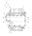
- FIG. 1 is a top view of a unit according to an embodiment of the present invention.
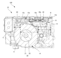
- FIG. 2 is a cross-sectional view taken along line II-II in FIG.
- FIG. 3 is a cross-sectional view taken along line III-III in FIG.
- FIG. 4 is a cross-sectional view taken along line IV-IV in FIG.
- FIG. 1 is a view of the unit 100 according to this embodiment as seen from above.
- FIG. 2 is a cross-sectional view taken along line II-II in FIG. 1.
- FIG. 3 is a cross-sectional view taken along line III-III in FIG. 1.
- FIG. 4 is a cross-sectional view taken along line IV-IV in FIG. 1.
- the direction perpendicular to the paper surface corresponds to the direction of gravity.
- the up-down direction corresponds to the direction of gravity.
- the unit can also be called, for example, a motor unit (a unit having at least a motor) or a power transmission device (a device having at least a power transmission mechanism).
- a motor is a rotating electric machine having an electric motor function and/or a generator function (at least one of an electric motor function and a generator function).
- a power transmission mechanism is, for example, a gear mechanism and/or a differential gear mechanism.
- a device (unit) having a motor and a power transmission mechanism is included in the concepts of both a motor unit and a power transmission device.
- the unit 100 includes a housing 10 having a first cover 11, a second cover 12, and a case 13.
- the unit 100 is mounted on a vehicle, which is an electric vehicle.
- the first cover 11 covers the opening of the cylindrical case 13 from one axial side (the lower side in FIG. 1)
- the second cover 12 covers the opening of the case 13 from the other axial side.
- the case 13 also has a third cover 13a that covers the opening on the upper side in the direction of gravity.
- the unit 100 further includes a motor 20, an inverter 30, a reduction mechanism (not shown), and a differential gear (not shown).
- the housing 10 has a motor accommodating chamber 14 that accommodates the motor 20, and an inverter accommodating chamber 15 that accommodates the inverter 30.
- the reduction mechanism and differential gear are also accommodated in a gear accommodating chamber 16 (see Figure 4) inside the second cover 12.
- the inverter 30 is electrically connected to the motor 20 and a battery (not shown).
- the motor 20 has a stator 21 that is mounted and fixed to the case 13, and a rotor 22 that can rotate inside the stator 21, and constitutes the driving source for the vehicle.
- the unit 100 has oil in the housing 10, and the oil is supplied, for example, to the reduction mechanism and differential gear in the second cover 12, to lubricate the gears in the reduction mechanism and the differential gear.
- the oil is also supplied, for example, to the motor 20 in the case 13, to lubricate the motor 20. Therefore, the oil that lubricates the motor 20 exists in the motor housing chamber 14 in a liquid, foam, or mist-like form.
- the inverter housing chamber 15 has a first bottom surface portion 15a, which also serves as a peripheral wall portion surrounding the outer periphery of the motor 20, and a second bottom surface portion 15b and a third bottom surface portion 15c, which are arranged on either side of the first bottom surface portion 15a.
- the first bottom surface portion 15a surrounds the outer periphery of the motor 20 that is highest in the direction of gravity. Both ends of the first bottom surface portion 15a are the dashed line portions adjacent to the arrow A in FIG. 2 on the peripheral wall portion of the motor 20.
- the second bottom surface portion 15b is the bottom surface from the peripheral wall of the motor 20 at the right end of the first bottom surface portion 15a to the right wall of the inverter housing chamber 15, as shown by arrow B in FIG. 2.
- the third bottom surface portion 15c is the bottom surface from the peripheral wall of the motor 20 at the left end of the first bottom surface portion 15a to the left wall of the inverter housing chamber 15.
- the inverter 30 is disposed above the second bottom surface portion 15b of the inverter accommodating chamber 15.
- a breather 40 is provided above the third bottom surface portion 15c of the inverter accommodating chamber 15 to reduce the air pressure difference by connecting the inside of the sealed motor accommodating chamber 14 with the inverter accommodating chamber 15.
- the breather 40 connects the inverter accommodating chamber 15 with the motor accommodating chamber 14 on the gear accommodating chamber 16 side of the opening S formed in the motor accommodating chamber 14 of the housing 10.
- the width of the opening S is within the range enclosed by the arrows A in FIG. 4.
- the breather 40 has an inlet on the motor accommodating chamber 14 side and an outlet on the inverter accommodating chamber 15 side.
- the first bottom surface portion 15a is disposed between the second bottom surface portion 15b and the third bottom surface portion 15c, surrounding the highest outer periphery of the motor 20 in the direction of gravity. Therefore, even if oil from the motor housing chamber 14 flows into the inverter housing chamber 15 via the breather 40, the oil (especially liquid or foamy oil) on the third bottom surface portion 15c is prevented from moving beyond the first bottom surface portion 15a to the second bottom surface portion 15b. As a result, even if oil flows into the inverter housing chamber 15 from the breather 40, the oil is more likely to remain on the third bottom surface portion 15c, and the oil is prevented from flowing toward the inverter 30 above the second bottom surface portion 15b.
- an external breathing hole 50 with a breathable filter 51 is formed on the outer wall of the inverter housing chamber 15 on the third bottom surface 15c side.
- the external breathing hole 50 connects the inverter housing chamber 15 to the outside of the housing 10, reducing the air pressure difference between the inside and outside, and also guides oil (especially mist-like oil) contained in the air in the inverter housing chamber 15 to the outer wall on the third bottom surface 15c side of the inverter housing chamber 15 where the filter 51 is located.
- the inverter accommodating chamber 15 will easily become positively pressurized due to the inflow of oil and air from the motor accommodating chamber 14. Therefore, the air in the inverter accommodating chamber 15 will easily flow to the outside of the housing 10 via the external breathing hole 50. As a result, the oil that flows from the breather 40 into the inverter accommodating chamber 15 will be guided to the outer wall on the third bottom portion 15c side of the inverter accommodating chamber 15, so the oil is more effectively prevented from flowing toward the inverter 30.
- the oil accumulated on the third bottom surface portion 15c can be drained by removing the detachable filter 51 and performing maintenance work to suck out the oil through the external breathing hole 50.
- the unit 100 has a housing 10 having a motor accommodation chamber 14 that accommodates the motor 20, and an inverter accommodation chamber 15 that accommodates the inverter 30.
- the inverter accommodation chamber 15 has a first bottom surface portion 15a that also serves as a peripheral wall portion that surrounds the outer periphery of the motor 20, and a second bottom surface portion 15b and a third bottom surface portion 15c that are arranged on either side of the first bottom surface portion 15a, with the control board 30a of the inverter 30 being arranged on the second bottom surface portion 15b side and the outlet of the breather 40 being arranged on the third bottom surface portion 15c side.
- the second bottom surface portion 15b and the third bottom surface portion 15c are arranged so as to sandwich the first bottom surface portion 15a.
- the oil is less likely to go beyond the first bottom surface portion 15a to the second bottom surface portion 15b, and is more likely to remain on the third bottom surface portion 15c. Therefore, the oil coming out from the outlet of the breather 40 can be retained on the third bottom surface portion 15c in the inverter accommodation chamber 15 without being guided to the control board 30a of the inverter 30 arranged on the second bottom surface portion 15b side. Therefore, according to the above aspect, when the breather 40 is provided in the sealed space of the unit 100, it is possible to prevent oil from adhering to the control board 30a of the inverter 30, which is a component to which oil should not be attached.
- a breathable filter 51 is provided on the outer wall of the inverter housing chamber 15 on the side of the third bottom portion 15c.
- the oil coming out of the outlet of the breather 40 is mist-like oil that is easily scattered, it can be adsorbed by the breathable filter 51 provided on the outside of the third bottom surface portion 15c of the inverter housing chamber 15, and the oil can be prevented from flowing to the inverter 30 side.
- the air in the inverter housing chamber 15 easily flows from the external breathing hole 50 to the outside of the housing 10.
- the mist-like oil coming out of the outlet of the breather 40 is guided to the outside of the third bottom surface portion 15c of the inverter housing chamber 15, so that the oil can be more effectively prevented from flowing to the inverter 30 side. Therefore, according to the above aspect, it is possible to more effectively prevent oil from adhering to the control board 30a of the inverter 30.
- the filter 51 is detachably attached to the outer wall.
- the oil that has accumulated on the third bottom surface portion 15c can be easily drained by removing the filter 51 and performing maintenance work to suck out the oil through the external ventilation hole 50, making it possible to more effectively prevent oil from adhering to the control board 30a of the inverter 30.
Landscapes
- Engineering & Computer Science (AREA)
- Power Engineering (AREA)
- Motor Or Generator Frames (AREA)
- General Details Of Gearings (AREA)
Priority Applications (2)
| Application Number | Priority Date | Filing Date | Title |
|---|---|---|---|
| JP2025547191A JPWO2025062785A1 (https=) | 2023-09-22 | 2024-07-03 | |
| CN202480042443.9A CN121399829A (zh) | 2023-09-22 | 2024-07-03 | 组件 |
Applications Claiming Priority (2)
| Application Number | Priority Date | Filing Date | Title |
|---|---|---|---|
| JP2023-158470 | 2023-09-22 | ||
| JP2023158470 | 2023-09-22 |
Publications (1)
| Publication Number | Publication Date |
|---|---|
| WO2025062785A1 true WO2025062785A1 (ja) | 2025-03-27 |
Family
ID=95072564
Family Applications (1)
| Application Number | Title | Priority Date | Filing Date |
|---|---|---|---|
| PCT/JP2024/024040 Pending WO2025062785A1 (ja) | 2023-09-22 | 2024-07-03 | ユニット |
Country Status (3)
| Country | Link |
|---|---|
| JP (1) | JPWO2025062785A1 (https=) |
| CN (1) | CN121399829A (https=) |
| WO (1) | WO2025062785A1 (https=) |
Citations (7)
| Publication number | Priority date | Publication date | Assignee | Title |
|---|---|---|---|---|
| JPH0865945A (ja) | 1994-08-26 | 1996-03-08 | Aqueous Res:Kk | モータ駆動装置 |
| JPH09182352A (ja) | 1995-12-26 | 1997-07-11 | Aisin Aw Co Ltd | モータ駆動装置 |
| JP2012082930A (ja) | 2010-10-14 | 2012-04-26 | Toyota Motor Corp | 電気自動車用駆動装置 |
| JP2016019436A (ja) | 2014-07-11 | 2016-02-01 | Ntn株式会社 | 車両用モータ駆動装置のブリーザ構造 |
| WO2020179218A1 (ja) * | 2019-03-06 | 2020-09-10 | 日本電産株式会社 | モータユニット |
| JP2020178481A (ja) * | 2019-04-19 | 2020-10-29 | 日本電産株式会社 | 駆動装置 |
| WO2022209623A1 (ja) * | 2021-03-31 | 2022-10-06 | 株式会社アイシン | 車両用駆動装置 |
-
2024
- 2024-07-03 JP JP2025547191A patent/JPWO2025062785A1/ja active Pending
- 2024-07-03 WO PCT/JP2024/024040 patent/WO2025062785A1/ja active Pending
- 2024-07-03 CN CN202480042443.9A patent/CN121399829A/zh active Pending
Patent Citations (7)
| Publication number | Priority date | Publication date | Assignee | Title |
|---|---|---|---|---|
| JPH0865945A (ja) | 1994-08-26 | 1996-03-08 | Aqueous Res:Kk | モータ駆動装置 |
| JPH09182352A (ja) | 1995-12-26 | 1997-07-11 | Aisin Aw Co Ltd | モータ駆動装置 |
| JP2012082930A (ja) | 2010-10-14 | 2012-04-26 | Toyota Motor Corp | 電気自動車用駆動装置 |
| JP2016019436A (ja) | 2014-07-11 | 2016-02-01 | Ntn株式会社 | 車両用モータ駆動装置のブリーザ構造 |
| WO2020179218A1 (ja) * | 2019-03-06 | 2020-09-10 | 日本電産株式会社 | モータユニット |
| JP2020178481A (ja) * | 2019-04-19 | 2020-10-29 | 日本電産株式会社 | 駆動装置 |
| WO2022209623A1 (ja) * | 2021-03-31 | 2022-10-06 | 株式会社アイシン | 車両用駆動装置 |
Also Published As
| Publication number | Publication date |
|---|---|
| JPWO2025062785A1 (https=) | 2025-03-27 |
| CN121399829A (zh) | 2026-01-23 |
Similar Documents
| Publication | Publication Date | Title |
|---|---|---|
| CN103732953B (zh) | 传动装置 | |
| JP4074278B2 (ja) | バッフルプレート排油構造 | |
| JP4671267B2 (ja) | 自動変速機の漏油防止装置 | |
| CN104074923B (zh) | 驱动力传递装置 | |
| CN112583204A (zh) | 压力平衡系统 | |
| JP6461222B2 (ja) | オイルストレーナ及び動力伝達装置 | |
| CN108215788A (zh) | 动力装置 | |
| CN103542079B (zh) | 动力传递装置的润滑-通气结构 | |
| JP5220722B2 (ja) | 歯車減速機の軸封部構造 | |
| CN108692008A (zh) | 变速器的控制装置单元安装构造 | |
| JP2003214530A (ja) | トランスファのブリーザ構造 | |
| WO2025062785A1 (ja) | ユニット | |
| JP5912244B2 (ja) | 電動機ユニット | |
| JP2019173943A (ja) | 車両用駆動装置 | |
| JP7455486B2 (ja) | 電動オイルポンプの配置構造、および動力伝達装置 | |
| CA2548051C (en) | Helicopter drive with air-oil separator | |
| JP2015048926A (ja) | インホイールモータ駆動装置及びエアーブリーザ装置 | |
| JP4121975B2 (ja) | ベルト式無段変速機 | |
| WO2025062786A1 (ja) | ユニット | |
| US20180335094A1 (en) | Power transmission apparatus | |
| CN119654506A (zh) | 通气结构 | |
| CN118269637A (zh) | 油冷装置、动力总成及车辆 | |
| CN103154516B (zh) | 铁道车辆用空气压缩装置 | |
| JP7452423B2 (ja) | モータ | |
| CN217814868U (zh) | 减速器壳体、减速器及用于电动车辆的动力组件 |
Legal Events
| Date | Code | Title | Description |
|---|---|---|---|
| 121 | Ep: the epo has been informed by wipo that ep was designated in this application |
Ref document number: 24867869 Country of ref document: EP Kind code of ref document: A1 |
|
| ENP | Entry into the national phase |
Ref document number: 2025547191 Country of ref document: JP Kind code of ref document: A |
|
| WWE | Wipo information: entry into national phase |
Ref document number: 2025547191 Country of ref document: JP |
|
| WWE | Wipo information: entry into national phase |
Ref document number: 2024867869 Country of ref document: EP |