WO2025062542A1 - 回転電機、回転電機の回転子 - Google Patents
回転電機、回転電機の回転子 Download PDFInfo
- Publication number
- WO2025062542A1 WO2025062542A1 PCT/JP2023/034153 JP2023034153W WO2025062542A1 WO 2025062542 A1 WO2025062542 A1 WO 2025062542A1 JP 2023034153 W JP2023034153 W JP 2023034153W WO 2025062542 A1 WO2025062542 A1 WO 2025062542A1
- Authority
- WO
- WIPO (PCT)
- Prior art keywords
- magnet
- electric machine
- rotating electric
- rotor core
- rotor
- Prior art date
- Legal status (The legal status is an assumption and is not a legal conclusion. Google has not performed a legal analysis and makes no representation as to the accuracy of the status listed.)
- Pending
Links
Images

Classifications
-
- H—ELECTRICITY
- H02—GENERATION; CONVERSION OR DISTRIBUTION OF ELECTRIC POWER
- H02K—DYNAMO-ELECTRIC MACHINES
- H02K1/00—Details of the magnetic circuit
- H02K1/06—Details of the magnetic circuit characterised by the shape, form or construction
- H02K1/22—Rotating parts of the magnetic circuit
- H02K1/27—Rotor cores with permanent magnets
- H02K1/2706—Inner rotors
- H02K1/272—Inner rotors the magnetisation axis of the magnets being perpendicular to the rotor axis
- H02K1/274—Inner rotors the magnetisation axis of the magnets being perpendicular to the rotor axis the rotor consisting of two or more circumferentially positioned magnets
- H02K1/2753—Inner rotors the magnetisation axis of the magnets being perpendicular to the rotor axis the rotor consisting of two or more circumferentially positioned magnets the rotor consisting of magnets or groups of magnets arranged with alternating polarity
- H02K1/276—Magnets embedded in the magnetic core, e.g. interior permanent magnets [IPM]
Definitions
- the present invention relates to rotating electric machines and rotors for rotating electric machines.
- Patent Document 1 discloses a configuration in which grooves are arranged on the outer circumferential surface between tangent line 1 and a reference line in order to reduce torque ripple.
- the objective of the present invention is to provide a rotating electric machine and a rotor for the rotating electric machine that reduce torque ripple while maintaining torque.
- a rotating electric machine comprising a magnet and a rotor core having a magnet hole into which the magnet is inserted, the magnet including a first magnet and a second magnet arranged in a V-shape radially inward from the first magnet, the rotor core having a flux barrier formed facing the radially outer side surface of the second magnet, a bridge formed between the second magnet and the flux barrier, and a second groove formed on the outer peripheral surface of the rotor core, at least a portion of which faces the radially outer side surface of the second magnet.
- the present invention provides a rotating electric machine and a rotor for the rotating electric machine that reduce torque ripple while maintaining torque.
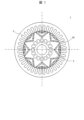
- FIG. 2 is a diagram illustrating the structure of a rotor of a rotating electric machine according to an embodiment of the present invention.
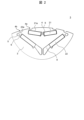
- FIG. 2 is a diagram illustrating the structure of a rotor of a rotating electric machine according to an embodiment of the present invention.
- the rotating electric machine 1 has a stator core 2 and a rotor core 3.
- the rotor core 3 has a plurality of magnets 20 inserted into magnet holes.
- the magnets 20 (Fig. 2, Fig. 3) As shown in Fig. 2, the magnets 20 (Fig. 1) inserted into the multiple magnet holes 9 of the rotor core 3 include a first magnet 21 and a second magnet 22.
- the first magnets 21 are arranged in two V-shapes in the circumferential direction with the d-axis between them.
- the second magnets 22 are arranged in a V-shape radially inward of the first magnets 21 with the d-axis between them.
- the rotor core 3 has a first groove 4a and a second groove 4b on the outer peripheral surface 4 of the rotor core.
- the first groove 4a is formed on the outer peripheral surface facing the radially outer main surface 21a of the first magnet 21.
- the second groove 4b is formed on the outer peripheral surface 4 of the rotor core 3 such that at least a portion of it faces the radially outer side surface 22a of the second magnet 22.
- the rotor core 3 also has a flux barrier 5 and a bridge 6.
- the flux barrier 5 faces the radially outer side surface 22a of the second magnet 22, and is formed between the second magnet 22 and the outer peripheral surface 4.
- the bridge 6 is formed between the second magnet 22 and the flux barrier 5.
- the second groove 4b is formed on the q-axis side with reference to an imaginary line 8 that connects the corner 22b of the second magnet 22 that is closest to the outer circumferential surface 4 and the center of the rotor core 3.
- the innermost portion 14 located on the innermost periphery of the second groove 4b is either in the same radial position as the outermost portion located on the outermost periphery of the flux barrier 5, or is located radially inward of the outermost portion of the flux barrier 5.
- the magnetic path between the first groove 4a and the first magnet 21 is narrower than before, making it easier for magnetic flux to flow from the rotor core 3 to the stator core 2 in the air gap between the rotor core 3 and the stator core 2, thereby increasing torque.
- the magnetic path between the second groove 4b and the flux barrier 5 midway to the inner diameter side it is easier for magnetic flux to flow from the rotor core 3 to the stator core 2 in the air gap between the rotor core 3 and the stator core 2, thereby increasing torque.
- a rotating electric machine 1 including a magnet 20 and a rotor core 3 having a magnet hole 9 into which the magnet 20 is inserted, the magnet 20 including a first magnet 21 and a second magnet 22 arranged in a V-shape radially inward from the first magnet 21, the rotor core 3 including a flux barrier 5 formed facing the radially outer side surface of the second magnet 22, a bridge 6 formed between the second magnet 22 and the flux barrier 5, and a second groove 4b formed on the outer circumferential surface of the rotor core 3, at least a portion of which faces the radially outer side surface of the second magnet 22.
- a rotating electric machine 1 can be provided in which torque ripple is reduced while torque is maintained.
- the second groove 4b has an innermost portion 14 that is located at the same radial position as the outermost portion of the flux barrier 5, or is located radially inward of the outermost portion of the flux barrier 5. This makes it possible to reduce torque ripple while maintaining torque.
- the rotor core 3 has a first groove 4a formed on the outer circumferential surface thereof facing the radially outer principal surface 21a of the first magnet 21. This makes it possible to reduce torque ripple while maintaining torque.
- the second groove 4b is formed on the q-axis side with respect to the imaginary line 8 that connects the corner 22b of the second magnet 22 that is closest to the outer circumferential surface and the center of the rotor core 3. In this way, it is possible to reduce torque ripple while maintaining the torque.
- the rotating electric machine 1 has a rotor that employs the above-mentioned configuration. In this way, it is possible to provide a rotor for the rotating electric machine 1 that reduces torque ripple while maintaining torque.
- the present invention is not limited to the above-described embodiment, and various modifications and other configurations can be combined without departing from the spirit of the invention. Furthermore, the present invention is not limited to those having all of the configurations described in the above-described embodiment, and also includes those in which some of the configurations have been omitted.
Landscapes
- Engineering & Computer Science (AREA)
- Power Engineering (AREA)
- Permanent Field Magnets Of Synchronous Machinery (AREA)
Priority Applications (3)
| Application Number | Priority Date | Filing Date | Title |
|---|---|---|---|
| JP2025547056A JPWO2025062542A1 (https=) | 2023-09-20 | 2023-09-20 | |
| PCT/JP2023/034153 WO2025062542A1 (ja) | 2023-09-20 | 2023-09-20 | 回転電機、回転電機の回転子 |
| CN202380102323.9A CN121866701A (zh) | 2023-09-20 | 2023-09-20 | 旋转电机、旋转电机的转子 |
Applications Claiming Priority (1)
| Application Number | Priority Date | Filing Date | Title |
|---|---|---|---|
| PCT/JP2023/034153 WO2025062542A1 (ja) | 2023-09-20 | 2023-09-20 | 回転電機、回転電機の回転子 |
Publications (1)
| Publication Number | Publication Date |
|---|---|
| WO2025062542A1 true WO2025062542A1 (ja) | 2025-03-27 |
Family
ID=95072471
Family Applications (1)
| Application Number | Title | Priority Date | Filing Date |
|---|---|---|---|
| PCT/JP2023/034153 Pending WO2025062542A1 (ja) | 2023-09-20 | 2023-09-20 | 回転電機、回転電機の回転子 |
Country Status (3)
| Country | Link |
|---|---|
| JP (1) | JPWO2025062542A1 (https=) |
| CN (1) | CN121866701A (https=) |
| WO (1) | WO2025062542A1 (https=) |
Citations (5)
| Publication number | Priority date | Publication date | Assignee | Title |
|---|---|---|---|---|
| WO2018159181A1 (ja) * | 2017-02-28 | 2018-09-07 | 日立オートモティブシステムズ株式会社 | 回転電機の回転子及びこれを備えた回転電機 |
| JP2021097434A (ja) * | 2019-12-13 | 2021-06-24 | 本田技研工業株式会社 | 回転電機のロータおよび回転電機 |
| JP2021106474A (ja) * | 2019-12-26 | 2021-07-26 | 日産自動車株式会社 | 回転電機の回転子及び回転電機 |
| WO2023007707A1 (ja) * | 2021-07-30 | 2023-02-02 | 川崎重工業株式会社 | ロータ及びモータ |
| JP2023042025A (ja) * | 2021-09-14 | 2023-03-27 | 株式会社明電舎 | 回転子 |
-
2023
- 2023-09-20 JP JP2025547056A patent/JPWO2025062542A1/ja active Pending
- 2023-09-20 CN CN202380102323.9A patent/CN121866701A/zh active Pending
- 2023-09-20 WO PCT/JP2023/034153 patent/WO2025062542A1/ja active Pending
Patent Citations (5)
| Publication number | Priority date | Publication date | Assignee | Title |
|---|---|---|---|---|
| WO2018159181A1 (ja) * | 2017-02-28 | 2018-09-07 | 日立オートモティブシステムズ株式会社 | 回転電機の回転子及びこれを備えた回転電機 |
| JP2021097434A (ja) * | 2019-12-13 | 2021-06-24 | 本田技研工業株式会社 | 回転電機のロータおよび回転電機 |
| JP2021106474A (ja) * | 2019-12-26 | 2021-07-26 | 日産自動車株式会社 | 回転電機の回転子及び回転電機 |
| WO2023007707A1 (ja) * | 2021-07-30 | 2023-02-02 | 川崎重工業株式会社 | ロータ及びモータ |
| JP2023042025A (ja) * | 2021-09-14 | 2023-03-27 | 株式会社明電舎 | 回転子 |
Also Published As
| Publication number | Publication date |
|---|---|
| CN121866701A (zh) | 2026-04-14 |
| JPWO2025062542A1 (https=) | 2025-03-27 |
Similar Documents
| Publication | Publication Date | Title |
|---|---|---|
| JP5288698B2 (ja) | 永久磁石式リラクタンス型回転電機 | |
| JP4311182B2 (ja) | 回転電機の回転子 | |
| EP1813010B1 (en) | Design of the magnet and webs in interior permanent magent rotors | |
| JP6507273B2 (ja) | 永久磁石埋込型電動機のためのロータ及びそれを用いた電動機 | |
| JP2001025209A (ja) | 電動機のロータ | |
| WO2019215853A1 (ja) | 回転電機の回転子構造 | |
| JP6191370B2 (ja) | 同期電動機 | |
| JP6315086B2 (ja) | 永久磁石埋め込み式回転電機 | |
| CN113890227B (zh) | 转子结构、电机结构和电子装置 | |
| JP6601169B2 (ja) | 回転電機 | |
| EP4047788B1 (en) | Rotary electric machine | |
| WO2018066647A1 (ja) | 同期リラクタンス型回転電機 | |
| JP7615913B2 (ja) | 回転電機 | |
| JP2000166135A (ja) | ブラシレスモータ | |
| JP2009106001A (ja) | 回転電機 | |
| CN112152351B (zh) | 用于电机的转子、用于车辆的电机及车辆 | |
| WO2025062542A1 (ja) | 回転電機、回転電機の回転子 | |
| JP2006333656A (ja) | 回転電機の回転子及びそれを用いた回転電機 | |
| JP2023102517A (ja) | ロータ及び回転電機 | |
| CN117674474A (zh) | 旋转电机 | |
| JP7651724B2 (ja) | 回転電機の回転子 | |
| JP7578081B2 (ja) | 回転電機 | |
| US20240055918A1 (en) | Permanent magnet rotor and permanent magnet rotary electric machine | |
| JP2021136754A (ja) | 回転電機のロータの磁石位置設定方法 | |
| JP6210160B2 (ja) | 同期リラクタンス回転電機 |
Legal Events
| Date | Code | Title | Description |
|---|---|---|---|
| 121 | Ep: the epo has been informed by wipo that ep was designated in this application |
Ref document number: 23953030 Country of ref document: EP Kind code of ref document: A1 |
|
| ENP | Entry into the national phase |
Ref document number: 2025547056 Country of ref document: JP Kind code of ref document: A |