WO2025057739A1 - アンテナ装置 - Google Patents
アンテナ装置 Download PDFInfo
- Publication number
- WO2025057739A1 WO2025057739A1 PCT/JP2024/030730 JP2024030730W WO2025057739A1 WO 2025057739 A1 WO2025057739 A1 WO 2025057739A1 JP 2024030730 W JP2024030730 W JP 2024030730W WO 2025057739 A1 WO2025057739 A1 WO 2025057739A1
- Authority
- WO
- WIPO (PCT)
- Prior art keywords
- cushion
- core
- case
- antenna device
- coil
- Prior art date
- Legal status (The legal status is an assumption and is not a legal conclusion. Google has not performed a legal analysis and makes no representation as to the accuracy of the status listed.)
- Pending
Links
Images



Classifications
-
- H—ELECTRICITY
- H01—ELECTRIC ELEMENTS
- H01Q—ANTENNAS, i.e. RADIO AERIALS
- H01Q1/00—Details of, or arrangements associated with, antennas
- H01Q1/40—Radiating elements coated with or embedded in protective material
-
- H—ELECTRICITY
- H01—ELECTRIC ELEMENTS
- H01Q—ANTENNAS, i.e. RADIO AERIALS
- H01Q7/00—Loop antennas with a substantially uniform current distribution around the loop and having a directional radiation pattern in a plane perpendicular to the plane of the loop
- H01Q7/06—Loop antennas with a substantially uniform current distribution around the loop and having a directional radiation pattern in a plane perpendicular to the plane of the loop with core of ferromagnetic material
- H01Q7/08—Ferrite rod or like elongated core
Definitions
- the present invention relates to an antenna device.
- Patent document 1 describes an antenna device that includes a wound body made of a magnetic core and a coil, a case that houses the wound body, and a foam that is filled between the wound body and the case.
- a cushion made of resin rubber or the like may be used instead of the foam described in Patent Document 1.
- the cushion is formed to fit tightly against the case with no gaps, as with the foam, it can be difficult to fit the cushion into the case, which can result in a long time required for assembling the antenna device.
- One object of the present invention is to easily assemble an antenna device. Other objects of the present invention will become apparent from the description of this specification.
- One aspect of the present invention is an antenna device that includes a case, a core having a magnetic body housed in the case, a coil housed in the case and wound around the core, and a cushion located between the case and the core or the coil, and the area of a first contact surface between the case and the cushion is equal to or less than the area of a surface of the cushion facing the case.
- the above aspects of the present invention make it easy to assemble the antenna device.
- FIG. 1 is a perspective view showing an antenna device 10 of the present embodiment with a case 11 removed.
- FIG. 1 is an exploded perspective view of an antenna device 10 according to the present embodiment.
- 2 is a cross-sectional view of the YZ plane taken along line AA in FIG. 1.
- FIG. 4 is an enlarged view of the dashed line portion of FIG. 3.
- 11A is a perspective view showing a state in which a case 11A and a housing 18A are removed from an antenna device 10A of a first modified example.
- FIG. 11 is a perspective view showing a state in which a case 11B and a housing 18B are removed from an antenna device 10B of a second modified example.
- FIG. FIG. 10 is an exploded perspective view of an antenna device 10C according to a third modified example.
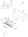
- Fig. 1 is a perspective view showing an antenna device 10 of this embodiment with a case 11 removed.
- Fig. 2 is an exploded perspective view of the antenna device 10 of this embodiment.
- Fig. 3 is a cross-sectional view of the YZ plane taken along line AA in Fig. 1.
- the direction from the core 12 (described below) toward the substrate 16 (described below) is the "+Z direction", and the opposite direction (i.e., the direction from the substrate 16 toward the core 12) is the "-Z direction”.
- the direction from the core 12 toward the first cushion body 21 (described below) of the cushion 14 is the "+Y direction”
- the opposite direction i.e., the direction from the first cushion body 21 of the cushion 14 toward the core 12
- the directions perpendicular to the +Z and +Y directions are the "+X direction” and "-X direction".
- Each of the +X direction, -X direction, +Y direction, -Y direction, +Z direction, and -Z direction has a fixed orientation. Rather than being fixed directions as described above, both the +X direction and the -X direction are sometimes simply called the "X direction”. Similarly, both the +Y direction and the -Y direction are sometimes simply called the "Y direction”. Furthermore, both the +Z direction and the -Z direction are sometimes simply called the "Z direction”.
- the +X, +Y, and +Z directions are each represented by a line segment with an arrow to make it easier to understand the directions in the antenna device 10. Note that the intersections of these lines with arrows do not represent the origin of the coordinate system.
- the antenna device 10 is an antenna device having an LF (Low Frequency) antenna.
- the LF antenna in the antenna device 10 of this embodiment is used in keyless entry systems and smart entry systems that remotely lock and unlock vehicle doors and trunks.
- the LF antenna in the antenna device 10 of this embodiment may also be used for engine start permission and auto-locking.
- the antenna device 10 may have an antenna that supports radio waves of other communication standards and frequency bands other than the LF band.
- the antenna device 10 is attached to a predetermined location of the vehicle, such as inside a door panel, trunk, hatchback, mirror, or inside the passenger compartment. However, the location where the antenna device 10 is attached can be changed as appropriate depending on the desired directivity, etc.
- the antenna device 10 may be attached to various locations, such as inside a door panel, trunk, hatchback, mirror, or inside the passenger compartment, as well as the vehicle's windshield, rear window, inside the instrument panel, top of the dashboard, overhead console, bumper, license plate mounting portion, pillar, spoiler, etc. Also, multiple antenna devices 10 may be attached to a single vehicle for different installation locations.
- the antenna device 10 is not limited to being attached to a vehicle, but may also be brought into a vehicle and used within the vehicle.
- the antenna device 10 of this embodiment is intended to be used in a "vehicle” that is a vehicle with wheels, the present invention is not limited to this, and may be used in, for example, an aircraft such as a drone, a probe, construction machinery without wheels, agricultural machinery, a ship, or other mobile object.
- the antenna device 10 may be an antenna used for objects other than mobile objects, such as a surveying antenna, a reference station antenna, a transmitting antenna and a reference antenna in an anechoic chamber, etc.
- the LF antenna in the antenna device 10 of this embodiment is compatible with radio waves in the LF band (e.g., 30 kHz to 300 kHz).
- the LF antenna in the antenna device 10 of this embodiment may be compatible with radio waves in a frequency band other than the 30 kHz to 300 kHz band.
- the antenna device 10 of this embodiment may have multiple LF antennas, or may have an antenna other than an LF antenna.
- the antenna of the antenna device 10 may be compatible with radio waves in multiple frequency bands.
- the antenna device 10 has a case 11, a core 12, a coil 13, a cushion 14, a holder 15, a substrate 16, and a capacitor 17.
- the coil 13 wound around the core 12 and the capacitor 17 enable the antenna device 10 to handle radio waves in the LF frequency band.
- the core 12, the coil 13, the cushion 14, the holder 15, the substrate 16, and the capacitor 17 may be collectively referred to as the "antenna body.”
- the antenna body of the antenna device 10 is connected to a connector (not shown) via a cable 19.
- the antenna device 10 is a cable-type antenna device.
- the antenna device 10 may also be a connector-type antenna device with an integrated connector.
- the case 11 is a member that constitutes the exterior of the antenna device 10.
- the case 11 is formed in the shape of a rectangular parallelepiped cylinder that is elongated in the Z direction and has a bottom.
- An opening 110 is formed at the end of the case 11 on the +Z direction side.
- the opening 110 is an opening for accommodating the antenna body inside the case 11.
- the antenna body is accommodated inside the case 11, and a sealant such as silicone is filled on the side of the opening 110, and the sealant is allowed to solidify. This makes it possible to seal the antenna body accommodated inside the case 11.
- the antenna device 10 has a waterproof structure for the antenna body.
- An engagement hole 111 is formed on each of the +Y side and -Y side of the case 11.
- the edge of the engagement hole 111 is engaged with an engagement claw 151 (described below) of the holder 15.
- an engagement claw 151 (described below) of the holder 15.
- Case 11 is formed from an insulating resin such as PBT or ABS. However, case 11 may be formed from a material other than insulating resin that transmits radio waves. Case 11 may also be composed of an insulating resin portion and a portion of another material that transmits radio waves, and components may be freely combined.
- insulating resin such as PBT or ABS.
- case 11 may be formed from a material other than insulating resin that transmits radio waves. Case 11 may also be composed of an insulating resin portion and a portion of another material that transmits radio waves, and components may be freely combined.
- the core 12 is a member having a magnetic body.
- the core 12 is formed of a magnetic material such as ferrite.
- the core 12 may be formed of a magnetic material other than ferrite.
- the core 12 is formed in a rectangular parallelepiped shape that is elongated in the Z direction.
- the core 12 is held by the holder 15 together with the coil 13 wound around the outer circumference of the core 12, and is housed in the case 11.
- the coil 13 is a component that constitutes the inductance of the antenna body.
- the coil 13 is wound around the core 12.
- the coil 13 is wound around the core 12 around an axis along the Z direction, and has a dense region 131 with a large number of turns per unit length in the Z direction, and a sparse region 132 with a smaller number of turns per unit length in the Z direction than the dense region 131.
- the coil 13 in this embodiment has three dense regions 131 and two sparse regions 132 arranged from the +Z direction side to the -Z direction side so that the dense regions 131 and the sparse regions 132 alternate.
- the number of dense regions 131 (three) is greater than the number of sparse regions 132 (two), but the number of sparse regions 132 may be greater than or equal to the number of dense regions 131.
- the coil 13 does not have to have dense regions 131 and sparse regions 132, and may be wound around the core 12 so that, for example, the number of turns per unit length in the Z direction is constant. In other words, the manner in which the coil 13 is wound around the core 12 can be changed as appropriate depending on the desired antenna characteristics of the LF antenna.
- one and the other ends of the coil 13 are located on the +Z direction side and are connected to the board 16 by soldering.
- the coil 13 is electrically connected to electronic components including the capacitor 17 on the board 16.
- the coil 13 wound around the core 12 and the board 16 on which the capacitor 17 is arranged are arranged adjacent to each other. That is, the antenna device 10 does not have a connecting part between the coil 13 and the board 16.
- the antenna device 10 does not have a connecting part between the coil 13 and the board 16.
- the cushion 14 is a member that suppresses the transmission of force from the case 11 to the inside of the cushion 14 in the antenna body in response to an external force applied to the antenna device 10.
- the cushion 14 also serves to reduce the impact force when the antenna device 10 is dropped.
- the cushion 14 is formed from an elastic material such as TPE or rubber (NBR, EPDM, etc.). However, the cushion 14 may be formed from other elastic materials.
- the cushion 14 has a first cushion body 21, a second cushion body 22, and a connection portion 23.
- the first cushion body 21 is a portion of the cushion 14 located on the +Y direction side (i.e., one side relative to the core 12).
- the second cushion body 22 is a portion of the cushion 14 located on the -Y direction side (i.e., the opposite side from the one side relative to the core 12).
- connection portion 23 is a portion that connects the first cushion body 21 and the second cushion body 22.
- the connection portion 23 By connecting the first cushion body 21 and the second cushion body 22 with the connection portion 23, it is possible to suppress external forces transmitted to the core 12 on both sides of the core 12 (both sides in the Y direction in this embodiment).
- the cushion 14 has multiple connection portions 23 on the side surfaces of the core 12 (the surfaces on the sides perpendicular to the Y direction).
- connection part 23 located on the -Z direction side has a protrusion 230.
- the protrusion 230 is a part for positioning the position of the core 12 within the case 11.
- the protrusion 230 protrudes in the +Z direction from the surface on the +Z direction side of the connection part 23, and has a surface (corresponding to a "positioning abutment surface") that abuts against the core 12 at the +Z direction end of the protrusion 230.
- connection part 23 located on the -Z direction side may not have the protrusion 230 (the surface on the +Z direction is flat), and the surface on the -Z direction side of the core 12 may protrude in the -Z direction to have a surface (positioning abutment surface) where the connection part 23 and the core 12 abut. Because the connection portion 23 has a surface that abuts against the core 12, when the antenna body including the core 12 is housed in the case 11, the core 12 and coil 13 can be easily positioned in the Y direction within the case 11, reducing the possibility of the core 12 and coil 13 being damaged within the case 11.
- the holder 15 is a member that holds the cushion 14, the core 12 around which the coil 13 is wound, and the substrate 16 on which the capacitor 17 is mounted.
- the holder 15 holds the core 12 around which the coil 13 is wound via the cushion 14, and holds the substrate 16 attached to the holder 15 by a snap fit.
- the holder 15 may also hold the substrate 16 that is attached by press fitting instead of by snap fitting.
- the holder 15 holds the board 16 by snap-fitting, so the board 16 is not completely fixed (i.e., the board 16 is allowed to move to a certain extent relative to the holder 15). Therefore, even if an external force is applied to the antenna body, the direct transmission of stress to the board 16 itself can be suppressed. This makes it possible to suppress peeling of the electronic components and the soldered portions of the board 16.
- the holder 15 has an engagement claw 151, a protrusion 152, an arm 153, and a board mounting surface 154.
- the engagement claw 151 is a portion that engages with the edge of the engagement hole 111 of the case 11. By engaging the engagement claw 151 with the edge of the engagement hole 111, it is possible to assemble the case 11 and the holder 15 (specifically, the holder 15 that holds the cushion 14, the core 12 around which the coil 13 is wound, and the board 16 on which the capacitor 17 is mounted).
- the arm 153 is a part that holds the substrate 16 attached to the holder 15 by snap fitting from the +Y direction side together with the protrusion 152.
- the arm 153 is formed to protrude in the +Z direction side and is formed to be elastically deformable in the -Z direction side.
- the board mounting surface 154 is a portion that holds the board 16 from the -Y direction side. By abutting the board 16 against the surface on the +Y direction side of the board mounting surface 154, the board mounting surface 154 holds the board 16 from the -Y direction side.
- Figure 4 is an enlarged view of the dashed area in Figure 3.
- the first cushion body 21 has a protrusion 210, a first leg 211, and a second leg 212.
- the second cushion body 22 has a protrusion 220, a first leg 221, and a second leg 222.
- the protrusion 220, the first leg 221, and the second leg 222 of the second cushion body 22 are described in the same manner as the protrusion 210, the first leg 211, and the second leg 212 of the first cushion body 21, unless otherwise specified.
- the protrusion 210 of the cushion first body 21 is a portion that protrudes further than other portions on the surface of the cushion first body 21 on the +Y direction side.
- the end of the protrusion 210 on the +Y direction side abuts against the inner surface (the surface on the -Y direction side) of the case 11.
- the cushion first body 21 has multiple protrusions 210 (two in this embodiment). However, the cushion first body 21 may have only one protrusion 210, or may have three or more protrusions 210.
- the protrusion 220 of the second cushion body 22 is a portion that protrudes further than other portions on the surface of the second cushion body 22 on the -Y direction side.
- the end of the protrusion 220 on the -Y direction side abuts against the inner surface (the surface on the +Y direction side) of the case 11.
- the second cushion body 22 has multiple protrusions 220 (two in this embodiment). However, the second cushion body 22 may have only one protrusion 220, or may have three or more protrusions 220.
- the contact surface between the cushion 14 and the case 11 may be referred to as the "first contact surface 31."
- Multiple (two in this embodiment) protrusions 210 contact the inner surface of the case 11 (the surface on the -Y direction side), and multiple (two in this embodiment) protrusions 220 contact the inner surface of the case 11 (the surface on the +Y direction side). Therefore, the first contact surface 31 is a surface that combines the contact surface between the multiple protrusions 210 and the case 11 and the contact surface between the multiple protrusions 220 and the case 11.
- the surface of the cushion 14 facing the case 11 (in this embodiment, the surface on the +Y direction side of the first cushion body 21 and the surface on the -Y direction side of the second cushion body 22) is formed so as to fit closely to the inner surface of the case 11 without any gaps, it may become difficult to store the cushion 14 in the case 11. This is because a large force is required to store the cushion 14 in the case 11 due to friction caused by the contact surfaces between the cushion 14 and the case 11.
- the cushion 14 is formed from an elastic material such as rubber, the friction caused by the contact surfaces between the cushion 14 and the case 11 becomes large.
- the cushion 14 has only a portion of its surface facing the case 11 (in this embodiment, the surface on the +Y side of the cushion first body 21 and the surface on the -Y side of the cushion second body 22) abutting against the inner surface of the case 11, thereby reducing friction caused by the abutting surfaces between the cushion 14 and the case 11. This allows the cushion 14 to be easily accommodated in the case 11, and the antenna device 10 to be easily assembled.
- the cushion 14 has a protrusion 210 and abuts against the flat inner surface of the case 11, but the surface of the cushion 14 facing the case 11 (in this embodiment, the surface on the +Y direction side of the first cushion body 21 or the surface on the -Y direction side of the second cushion body 22) may be flat and a protrusion may be formed on the inner surface of the case 11.
- the friction caused by the abutting surfaces between the cushion 14 and the case 11 can be reduced by abutting only a portion of the surface of the case 11 facing the cushion 14 (in this embodiment, the inner surface of the case 11) that faces the cushion 14 against the cushion 14 (in this embodiment, the protrusion of the case 11).
- both the cushion 14 and the case 11 have protrusions, and the protrusions of the cushion 14 come into contact with the protrusions of the case 11, thereby reducing friction caused by the contact surfaces between the cushion 14 and the case 11.
- the area S1 of the first contact surface 31 between the case 11 and the cushion 14 is equal to or smaller than the area SA (see FIG. 2) of the surface of the cushion 14 facing the case 11 (S1 ⁇ SA).
- the area S1 of the first contact surface 31 is the sum of the area of the contact surface between the multiple protrusions 210 and the case 11 and the area of the contact surface between the multiple protrusions 220 and the case 11.
- the area SA is the sum of the area of the surface of the cushion first body 21 facing the case 11 and the area of the surface of the cushion second body 22 facing the case 11. This allows the cushion 14 to be easily accommodated in the case 11, and the antenna device 10 to be easily assembled.
- the first leg 211 and the second leg 212 of the first cushion body 21 are parts that protrude from the other parts on the surface of the first cushion body 21 on the -Y direction side.
- the first leg 211 is located on the +Z direction side
- the second leg 212 is located on the -Z direction side.
- the first cushion body 21 may have only one leg (protrusion) instead of multiple legs like the first leg 211 and the second leg 212.
- the -Y direction side ends of the first leg 211 and the second leg 212 each abut against the surface of the core 12 on the +Y direction side.
- the first cushion body 21 has multiple combinations of the first leg 211 and the second leg 212 (two in this embodiment).
- the first cushion body 21 may have only one combination of the first leg 211 and the second leg 212, or three or more combinations.
- each of the first leg 221 and the second leg 222 of the cushion second body 22 is a portion that protrudes from the other portions on the surface of the cushion second body 22 on the +Y direction side.
- the first leg 221 is located on the +Z direction side
- the second leg 222 is located on the -Z direction side.
- the cushion second body 22 may have only one leg (protrusion) instead of multiple legs like the first leg 221 and the second leg 222.
- the +Y direction end of each of the first leg 221 and the second leg 222 abuts on the surface of the core 12 on the -Y direction side.
- the cushion second body 22 has multiple combinations of the first leg 221 and the second leg 222 (two in this embodiment).
- the cushion second body 22 may have only one combination of the first leg 221 and the second leg 222, or may have three or more combinations.
- the contact surface between the cushion 14 and the core 12 may be referred to as the "second contact surface 32."
- the second contact surface 32 is the surface that combines the contact surfaces between these multiple legs and the core 12.
- the coil 13 is wound around the core 12.
- the second abutment surface 32 is located in the sparse region 132, not the dense region 131, of the coil 13 wound around the core 12.
- the ends of the multiple legs of the cushion 14 are in contact with at least a portion of the sparse region 13F2 of the coil 13 wound around the core 12.
- the cushion first body 21 in this embodiment, it includes a plurality of legs (two, the first leg 211 and the second leg 212, in this embodiment) corresponding to a certain protrusion 210, and the end of each of the plurality of legs abuts against the core 12.
- a plurality of legs two, the first leg 211 and the second leg 212, in this embodiment
- the end of each of the plurality of legs abuts against the core 12.
- there is one part where the cushion 14 and the case 11 abut the protrusion 210 in this embodiment
- the number of parts where the cushion 14 and the core 12 abut is greater than the number of parts where the cushion 14 and the case 11 abut (one in this embodiment). This distributes the external force transmitted to the core 12, and further suppresses damage to the core 12.
- the cushion 14 has a first leg 211 and a second leg 212 and abuts against the flat surface of the core 12, but the surface of the cushion 14 facing the core 12 (in this embodiment, the surface on the -Y direction side of the cushion first body 21) may be flat, and legs (protrusions) may be formed on the surface of the core 12 facing the cushion 14.
- both the cushion 14 and the core 12 have legs (protrusions), and the legs (protrusions) of the cushion 14 come into contact with the legs (protrusions) of the core 12, dispersing the external force transmitted to the core 12 and further preventing damage to the core 12.
- the antenna device 10 is manufactured through the following six procedures.
- the substrate 16 is prepared, and the capacitor 17 is attached by soldering.
- the capacitor 17 can be directly arranged on a metal terminal instead of the substrate 16.
- stress may be applied to the capacitor 17, which may damage the capacitor 17.
- the solderability when connecting the capacitor 17 to the metal terminal may not be good, and the metal terminal may need to be divided later. For this reason, by attaching the capacitor 17 to the substrate 16 as in this embodiment, damage to the capacitor 17 can be suppressed and the assembly workability can be improved.
- the capacitor 17 by attaching the capacitor 17 to the substrate 16, it can be easily attached to the holder 15 by snap-fitting or press-fitting in the step (2) described below (attaching the substrate 16 with the capacitor 17 attached to it to the holder 15).
- the substrate 16 with the capacitor 17 attached is mounted to the holder 15 by snap-fitting.
- the outline of the substrate 16 before mounting is indicated by a dashed line.
- the end of the substrate 16 on the ⁇ Z direction side is hooked onto the arm 153 of the holder 15, and the end of the substrate 16 on the +Z direction side is moved to the ⁇ Y direction side.
- the arm 153 is elastically deformed in the ⁇ Z direction by the pressing force of the end of the substrate 16 on the ⁇ Z direction side hooked onto the arm 153, while the substrate 16 is positioned so that the end of the substrate 16 on the +Z direction side is located on the ⁇ Y direction side of the protrusion 152.
- the method of attaching the substrate 16 to the holder 15 is not limited to snap-fitting, and may be, for example, press-fitting.
- a method of attaching the substrate 16 to the holder 15 by press-fitting may involve forming a resin protrusion on the holder 15 and pressing the substrate 16 into this protrusion to secure it. Attaching the substrate 16 to the holder 15 by snap-fitting or press-fitting eliminates the need for welding or gluing, and the substrate 16 can be easily attached to the holder 15.
- the substrate 16 may also be attached by forming a resin protrusion on the holder 15, inserting the protrusion into a hole formed in the substrate 16, and heat-welding the protrusion.
- the cushion 14 is attached to the core 12 around which the coil 13 is wound, from the outside of the holder 15.
- the cushion 14 has a first cushion body 21 and a second cushion body 22, and is attached so as to hold the core 12 from both sides, so that the cushion 14 can be prevented from easily falling off the core 12.
- the antenna body (core 12 around which coil 13 is wound, cushion 14, holder 15, and substrate 16 on which capacitor 17 is arranged) is housed in case 11.
- a sealant such as silicon is filled on the side of opening 110 of case 11, and the sealant is allowed to harden. This allows the antenna body housed inside case 11 to be sealed.
- the antenna device 10 of the present embodiment described above is a cable-type antenna device that is connected to a connector (not shown) via a cable 19.
- the antenna device may be a connector-type antenna device in which a connector is integrated. Two types of examples (a first modified example and a second modified example) of the connector-type antenna device will be described below.
- FIG. 5 is a perspective view showing the antenna device 10A of the first modified example with the case 11A and housing 18A removed.
- the antenna device 10A has an exterior consisting of a case 11A and a housing 18A, and other components (core 12, coil 13, cushion 14, holder 15, board 16, and capacitor 17) housed inside. Instead of the cable 19 of this embodiment, the antenna device 10A is connected to the board 16 and has a terminal 19A extending in the +Z direction.
- An engagement hole 111A is formed on both the +Y side and the -Y side of the case 11A.
- the edge of the engagement hole 111A engages with an engagement claw 181A (described below) of the housing 18A.
- the housing 18A has an engagement claw 181A on both the +Y side and the -Y side.
- the engagement claw 181A engages with the edge of the engagement hole 111A of the case 11A.
- the case 11A and the housing 18A can be assembled by the engagement claw 181A engaging with the edge of the engagement hole 111A.
- the rest of the configuration is the same as that of the antenna device 10 of this embodiment. Even in the antenna device 10A of the first modified example, the cushion 14 can be easily accommodated in the case 11A, and the antenna device 10A can be easily assembled.
- Figure 6 is a perspective view showing the antenna device 10B of the second modified example with the case 11B and housing 18B removed.
- the antenna device 10A has an exterior consisting of a case 11B and a housing 18B, with other components (core 12, coil 13, cushion 14, holder 15, board 16, and capacitor 17) housed inside.
- the antenna device 10B is connected to the board 16 and has a terminal 19B arranged thereon.
- the terminal 19B is arranged so as to extend out in the -X direction.
- the engagement claw 181B engages with the edge of the engagement hole 111B, making it possible to assemble the case 11B and the housing 18B.
- the rest of the configuration is the same as that of the antenna device 10 of this embodiment. Even in the antenna device 10B of the first modified example, the cushion 14 can be easily accommodated in the case 11B, and the antenna device 10B can be easily assembled.
- the coil 13 is wound around the core 12 attached to the holder 15, and the cushion 14 is attached.
- the ends of the multiple legs of the cushion 14 are in contact with at least a part of the sparse region 132 of the coil 13 wound around the core 12.
- the ends of the multiple legs do not have to be in contact with the sparse region 132 of the coil 13.
- the cushion 14 may not be in contact with the coil 13 and may only be in contact with the core 12.
- FIG. 7 is an exploded perspective view of the antenna device 10C of the third modified example.
- the antenna device 10C of the third modified example has the same shape as the antenna device 10 of this embodiment, except that the position of the sparse region 132C in the coil 13C relative to the core 12 is different.
- the coil 13C has a dense region 131C and a sparse region 132C.
- the dense region 131C is wound around the core 12 like the antenna device 10 of this embodiment, but the sparse region 132C is wound around the outside of the holder 15 (specifically, the side surface of the holder 15 in the X direction). This allows the cushion 14 to be positioned so that it does not come into contact with the coil 13, but only with the core 12. This makes it possible to suppress changes in the winding state of the coil 13 and damage to the core 12 due to the cushion 14 coming into contact with the coil 13.
- the rest of the configuration of the antenna device 10C of the third modified example is the same as that of the antenna device 10 of this embodiment. Even with the antenna device 10C of the third modified example, the cushion 14 can be easily accommodated in the case 11, and the antenna device 10C can be easily assembled.
- Aspect 1 is an antenna device comprising a case, a core having a magnetic material housed in the case, a coil housed in the case and wound around the core, and a cushion positioned between the case and the core or the coil, wherein the area of a first abutment surface between the case and the cushion is less than or equal to the area of a surface of the cushion facing the case.
- the above-mentioned embodiment allows the antenna device to be easily assembled.
- the cushion has a second contact surface on the opposite side to the first contact surface, where the core and the cushion come into contact with each other.
- the above-mentioned aspect reduces the impact force when the antenna device is dropped, thereby preventing damage to the core and suppressing changes in the inductance of the antenna in the antenna device.
- the area of the second contact surface is larger than the area of the first contact surface.
- the above-mentioned embodiment allows the core to be protected more stably.
- the cushion includes a plurality of legs, each end of which abuts against the core.
- the above-mentioned aspect can disperse the external force transmitted to the core, further reducing damage to the core.
- the cushion has a first cushion body located on one side of the core, a second cushion body located on the opposite side of the core from the one side, and a connecting portion connecting the first cushion body and the second cushion body.
- the above-mentioned aspect makes it possible to suppress external forces transmitted to the core on both sides of the core.
- connection portion includes a positioning abutment surface that determines a position of the core within the case.
- the core 12 and the coil 13 can be easily positioned within the case.
- the present invention includes a holder and a substrate, the substrate being attached to the holder by snap-fitting or press-fitting.
- the substrate can be easily attached to the holder.
Landscapes
- Details Of Aerials (AREA)
Abstract
ケースと、前記ケースに収容され、磁性体を有するコアと、前記ケースに収容され、前記コアに巻回されたコイルと、前記ケースと、前記コア又は前記コイルとの間に位置するクッションと、を備え、前記ケースと前記クッションとの第1当接面の面積は、前記クッションにおける前記ケースに対向する側の面の面積以下である、アンテナ装置である。
Description
本発明は、アンテナ装置に関する。
特許文献1には、磁性体コアとコイルからなる巻回体と、当該巻回体が収容されるケースと、巻回体とケースの間に充填される発泡体とを備えるアンテナ装置が記載されている。
ところで、特許文献1に記載された発泡体の代わりに、樹脂製のゴム等で形成されたクッションを使用することがある。この場合、発泡体と同じようにクッションをケースに対して隙間なく密着するように形成すると、クッションをケースに収容することが難しくなり、アンテナ装置の組み立てに時間が掛かってしまうことがあった。
本発明の目的の一例は、アンテナ装置を容易に組み立てることにある。本発明の他の目的は、本明細書の記載から明らかになるであろう。
本発明の一態様は、ケースと、前記ケースに収容され、磁性体を有するコアと、前記ケースに収容され、前記コアに巻回されたコイルと、前記ケースと、前記コア又は前記コイルとの間に位置するクッションと、を備え、前記ケースと前記クッションとの第1当接面の面積は、前記クッションにおける前記ケースに対向する側の面の面積以下である、アンテナ装置である。
本発明の上記態様によれば、アンテナ装置を容易に組み立てることができる。
本明細書及び添付図面の記載により、少なくとも以下の事項が明らかとなる。
以下、図面を参照しながら本発明の好適な実施の形態を説明する。各図面に示される同一又は同等の構成要素、部材等には同一の符号を付し、適宜重複した説明は省略する。
==本実施形態==
図1は、本実施形態のアンテナ装置10においてケース11を取り外した様子を示す斜視図である。図2は、本実施形態のアンテナ装置10の分解斜視図である。図3は、図1のA-A線におけるYZ平面の断面図である。
図1は、本実施形態のアンテナ装置10においてケース11を取り外した様子を示す斜視図である。図2は、本実施形態のアンテナ装置10の分解斜視図である。図3は、図1のA-A線におけるYZ平面の断面図である。
<<方向等の定義>>
まず、図1,図2及び図3を参照しつつ、本実施形態のアンテナ装置10における方向等を定義する。
まず、図1,図2及び図3を参照しつつ、本実施形態のアンテナ装置10における方向等を定義する。
図1,図2及び図3に示すように、コア12(後述)から基板16(後述)に向かう方向を「+Z方向」とし、その反対方向(すなわち、基板16からコア12に向かう方向)を「-Z方向」とする。また、コア12からクッション14のクッション第1本体21(後述)に向かう方向を「+Y方向」とし、その反対方向(すなわち、クッション14のクッション第1本体21からコア12に向かう方向)を「-Y方向」とする。+Z方向及び+Y方向に直交する方向を「+X方向」及び「-X方向」とする。
+X方向,-X方向,+Y方向,-Y方向,+Z方向及び-Z方向の各々は、向きが決まった方向である。上述したような向きが決まった方向ではなく、+X方向及び-X方向の両方向を、単に「X方向」と呼ぶことがある。同様に、+Y方向及び-Y方向の両方向を、単に「Y方向」と呼ぶことがある。また、+Z方向及び-Z方向の両方向を、単に「Z方向」と呼ぶことがある。
図1,図2及び図3では、アンテナ装置10における方向等の理解を容易にするために、+X方向,+Y方向及び+Z方向の各々の方向を矢印付き線分で表している。なお、これらの矢印付き線分の交点は、座標原点を意味するものではない。
上述した方向等の定義については、特記した場合を除き、本明細書の他の実施形態においても共通である。
<<アンテナ装置10の概要>>
次に、上述した図1,図2及び図3を再び参照しながら、本実施形態のアンテナ装置10の概要を説明する。
次に、上述した図1,図2及び図3を再び参照しながら、本実施形態のアンテナ装置10の概要を説明する。
アンテナ装置10は、LF(Low Frequency)アンテナを有するアンテナ装置である。本実施形態のアンテナ装置10におけるLFアンテナは、車両のドアの施錠や解錠、車両のトランクの施錠や解錠などを遠隔操作で行うキーレスエントリーシステム、スマートエントリーシステムで用いられる。また、本実施形態のアンテナ装置10におけるLFアンテナは、エンジンの始動許可やオートロックに用いられても良い。但し、アンテナ装置10は、LF帯以外の、他の通信規格及び周波数帯の電波に対応するアンテナを有していても良い。
アンテナ装置10は、車両の所定の場所、例えば、ドアパネル内部、トランク、ハッチバック、ミラー、車室内部などに取り付けられている。但し、アンテナ装置10が取り付けられる位置は、所望の指向性等に応じて適宜変更できる。アンテナ装置10は、車両のドアパネル内部、トランク、ハッチバック、ミラー、車室内部以外に、例えば、車両のフロントガラス、リアガラス、インストルメントパネル内部、ダッシュボードの上部、オーバーヘッドコンソール、バンパー、ナンバープレートの取り付け部、ピラー、スポイラー等、様々な位置に取り付けられていても良い。また、アンテナ装置10は、一つの車両に設置場所別に複数個取付けられていても良い。
ここで、アンテナ装置10は、車両に取り付けられている態様に限られず、車両に持ち込まれ、車両内で用いられる態様も含まれる。また、本実施形態のアンテナ装置10は、車輪のついた乗り物である「車両」に用いられることとしたが、これに限られず、例えばドローン等の飛行体、探査機、車輪を有さない建機、農機、船舶等の移動体に用いられていても良い。さらに、アンテナ装置10は、測量用アンテナ、基準局用アンテナ、電波暗室の送信アンテナ及び基準アンテナ等、移動体以外に用いられるアンテナであっても良い。
本実施形態のアンテナ装置10におけるLFアンテナは、LF帯(例えば、30kHz~300kHz)の周波数帯の電波に対応する。但し、本実施形態のアンテナ装置10におけるLFアンテナは、30kHz~300kHz帯以外の周波数帯の電波に対応しても良い。さらに、本実施形態のアンテナ装置10は、複数のLFアンテナを有していても良いし、LFアンテナ以外のアンテナを有していても良い。アンテナ装置10が有するアンテナは、複数の周波数帯の電波に対応していても良い。
アンテナ装置10は、ケース11と、コア12と、コイル13と、クッション14と、ホルダ15と、基板16と、コンデンサ17とを有する。後述するように、コア12に巻回されたコイル13と、コンデンサ17とにより、アンテナ装置10は、LF帯の周波数帯の電波に対応することができる。以下の説明では、コア12と、コイル13と、クッション14と、ホルダ15と、基板16と、コンデンサ17とを合わせて「アンテナ本体」と呼ぶことがある。
アンテナ装置10のアンテナ本体は、不図示のコネクタにケーブル19を介して接続される。すなわち、アンテナ装置10は、ケーブル型のアンテナ装置である。しかし、後述する変形例(図5及び図6参照)のように、アンテナ装置10は、コネクタが一体化されたコネクタ型のアンテナ装置であっても良い。
ケース11は、アンテナ装置10の外装を構成する部材である。ケース11は、Z方向に細長い直方体の筒状に有底状に形成されている。ケース11の+Z方向側の端部には、開口110が形成されている。開口110は、アンテナ本体をケース11の内部に収容するための開口である。後述するように、アンテナ本体をケース11の内部に収容し、開口110の側においてシリコン等のシール剤を充填し、シール剤を固化させる。これにより、ケース11の内部に収容されたアンテナ本体を密封することができる。つまり、アンテナ装置10は、アンテナ本体の防水構造を有する。
ケース11の+Y方向側と、-Y方向側との各々には、係合孔111が形成されている。係合孔111は、その縁にホルダ15の係合爪151(後述)が係合する部位である。係合孔111の縁とホルダ15の係合爪151とが係合することによって、ケース11とホルダ15(具体的には、クッション14と、コイル13が巻回されたコア12と、コンデンサ17が搭載された基板16とを保持するホルダ15)とを組み付けることが可能である。
ケース11は、例えば、PBTやABS等の絶縁性の樹脂により形成されている。但し、ケース11は、絶縁性の樹脂以外であって、電波を透過する他の材料により形成されていても良い。また、ケース11は、絶縁性の樹脂の部分と、電波を透過する他の材料の部分とで構成されていても良く、部材を自由に組み合わせても良い。
コア12は、磁性体を有する部材である。コア12は、例えば、フェライト等の磁性体材料により形成されている。但し、コア12は、フェライト以外の磁性体材料により形成されていても良い。コア12は、Z方向に細長い直方体状に形成されている。そして、コア12は、コア12の外周に巻回されたコイル13と共にホルダ15に保持され、ケース11に収容されている。
コイル13は、アンテナ本体のインダクタンスを構成する部材である。コイル13は、コア12に巻回されている。コイル13は、Z方向に沿う軸を中心にコア12に巻回されており、Z方向の単位長さあたりの巻き数が多い密領域131と、密領域131よりもZ方向の単位長さあたりの巻き数が少ない疎領域132とを有する。
本実施形態におけるコイル13は、図2に示すように、+Z方向側から-Z方向側にかけて3つの密領域131と、2つの疎領域132とが、密領域131と疎領域132とが交互となるように配置されている。本実施形態では、密領域131の数(3つ)が疎領域132の数(2つ)より多いが、疎領域132の数が密領域131の数より多くてもよいし、同数でもよい。また、コイル13は、密領域131と疎領域132とを有さなくても良く、例えば、Z方向の単位長さあたりの巻き数が一定となるようコア12に巻回されていても良い。すなわち、コイル13のコア12に巻回する態様は、LFアンテナの所望とするアンテナ特性により適宜変更することができる。
図2に示すように、コイル13の一方側及び他方側の端部は、+Z方向側に位置し、基板16に半田付けにより接続される。これにより、コイル13は、基板16上のコンデンサ17を含む電子部品と電気的に接続される。ここで、コア12に巻回されたコイル13と、コンデンサ17が配置された基板16とは互いに隣接して配置されている。すなわち、アンテナ装置10は、コイル13と基板16との間に連結部等を有さない。コイル13と基板16とが互いに隣接して配置される(アンテナ装置10がコイル13と基板16との間に連結部等を有さない)ことにより、アンテナ装置10全体の大きさを変えない場合にはコア12やコイル13のサイズ(特にZ方向の長さ)を大きくすることができる。これにより、アンテナ装置10のアンテナの性能を向上させることができると共に、アンテナ装置10の部品点数を削減することができる。
クッション14は、アンテナ装置10に加わる外力に対し、ケース11からアンテナ本体におけるクッション14内部への力の伝達を抑制する部材である。また、クッション14は、アンテナ装置10落下時の衝撃力を緩和する部材でもある。アンテナ装置10がクッション14を有することにより、例えば、アンテナ装置10に加わる外力に起因するコイル13の巻回状態の変化やコア12の破損を抑制し、インダクタンスの変化を抑制することができる。
クッション14は、例えば、TPEやゴム等(NBRやEPDM等)の弾性体材料により形成されている。但し、クッション14は、その他の弾性体材料により形成されていても良い。
クッション14は、クッション第1本体21と、クッション第2本体22と、接続部23とを有する。クッション第1本体21は、クッション14のうち、+Y方向側(すなわち、コア12に対して一方側)に位置する部位である。クッション第2本体22は、クッション14のうち、-Y方向側(すなわち、コア12に対して上記一方側とは反対側)に位置する部位である。
接続部23は、クッション第1本体21とクッション第2本体22とを接続する部位である。接続部23によってクッション第1本体21とクッション第2本体22とを接続することにより、コア12の両面(本実施形態では、Y方向の両面)においてコア12に伝わる外力を抑制することができる。クッション14は、コア12の側面(Y方向に対して垂直な方向の側の面)において、複数の接続部23を有する。
図3に示すように、複数の接続部23のうち、-Z方向側に位置する接続部23は、突起230を有する。突起230は、ケース11内におけるコア12の位置を位置決めするための部位である。突起230は、接続部23の+Z方向側の面から+Z方向に突出し、突起230の+Z方向の端部において、コア12に当接する面(「位置決め当接面」に相当)を有する。但し、-Z方向側に位置する接続部23は、突起230を有さず(+Z方向の面が平坦であり)、コア12の-Z方向側の面が-Z方向に突出することで、接続部23とコア12とが当接する面(位置決め当接面)を有していても良い。接続部23がコア12に当接する面を有することにより、コア12を含むアンテナ本体をケース11に収容する際に、コア12及びコイル13をケース11内で容易にY方向に対する位置決めをすることができき、コア12及びコイル13がケース11内で破損する可能性を低減することができる。
クッション14のその他の説明については、後述する。
ホルダ15は、クッション14と、コイル13が巻回されたコア12と、コンデンサ17が搭載された基板16とを保持する部材である。ホルダ15は、クッション14を介してコイル13が巻回されたコア12を保持し、スナップフィットによりホルダ15に取り付けられた基板16を保持する。但し、ホルダ15は、スナップフィットではなく、圧入により取り付けられた基板16を保持しても良い。
本実施形態では、ホルダ15はスナップフィットにより基板16を保持しているため、基板16は完全に固定されていない(すなわち、基板16のホルダ15に対する移動がある程度許容されている)。したがって、アンテナ本体に外力が加わっても、基板16自体には直接応力が伝達されることを抑制することができる。これにより、電子部品と基板16の半田付け部分の剥離を抑制することができる。
ホルダ15は、係合爪151と、突起152と、腕153と、基板設置面154とを有する。
係合爪151は、ケース11の係合孔111の縁に係合する部位である。係合爪151が係合孔111の縁と係合することによって、ケース11とホルダ15(具体的には、クッション14と、コイル13が巻回されたコア12と、コンデンサ17が搭載された基板16とを保持するホルダ15)とを組み付けることが可能である。
突起152は、スナップフィットによりホルダ15に取り付けられた基板16を腕153と共に+Y方向側から保持する部位である。突起152は、-Z方向側に突出するように形成されている。ここで、基板16の-Z方向側の端部には切欠き(不図示)が形成されており、突起152はこの基板16の-Z方向側の切欠きに係合することにより、スナップフィットでホルダ15に取り付けられた基板16のX方向の移動を抑制することができる。
腕153は、スナップフィットによりホルダ15に取り付けられた基板16を突起152と共に+Y方向側から保持する部位である。腕153は、+Z方向側に突出するように形成され、-Z方向側に弾性変形可能に形成されている。
基板設置面154は、基板16を-Y方向側から保持する部位である。基板設置面154の+Y方向側の面に基板16を当接させることによって、基板設置面154は、基板16を-Y方向側から保持する。
基板16は、コンデンサ17を含む電子部品が配置される基板である。基板16は、例えば、プリント基板(PCB:Printed-Circuit Board)である。また、本実施形態のアンテナ装置10では、基板16は、リジッド基板であるが、これに限られず、フレキシブル基板であっても良い。なお、基板16には、コンデンサ17やグランドパターンのほか、フィルタ等の回路素子が別途配置されても良い。
コンデンサ17は、アンテナ本体のキャパシタンスを構成する部材である。コンデンサ17は、半田付け等により基板16に配置されている。コンデンサ17で形成されるキャパシタと、コア12に巻かれたコイル13で形成されるインダクタンスとによって、アンテナ本体は、上述したLF帯(例えば、30kHz~300kHz)の周波数帯の電波に対応することができる。
<<クッション14の詳細>>
以下では、上述した図1,図2及び図3を再び参照しつつ、新たに図4を参照しながら、クッション14の詳細な構成を説明する。
以下では、上述した図1,図2及び図3を再び参照しつつ、新たに図4を参照しながら、クッション14の詳細な構成を説明する。
図4は、図3の破線部分を拡大した図である。
クッション第1本体21は、突起210と、第1脚211と、第2脚212とを有する。また、クッション第2本体22は、突起220と、第1脚221と、第2脚222とを有する。クッション第2本体22における突起220,第1脚221及び第2脚222の説明については、特記した場合を除き、クッション第1本体21における突起210,第1脚211及び第2脚212と同様である。
クッション第1本体21における突起210は、クッション第1本体21の+Y方向側の面において、他の部分よりも突出している部分である。突起210の+Y方向側の端部は、ケース11の内面(-Y方向側の面)に対して当接している。クッション第1本体21は、複数(本実施形態では、2つ)の突起210を有する。但し、クッション第1本体21は、突起210を1つのみ有していても良いし、3つ以上有していても良い。
また、クッション第2本体22における突起220は、クッション第2本体22の-Y方向側の面において、他の部分よりも突出している部分である。突起220の-Y方向側の端部は、ケース11の内面(+Y方向側の面)に対して当接している。クッション第2本体22は、複数(本実施形態では、2つ)の突起220を有する。但し、クッション第2本体22は、突起220を1つのみ有していても良いし、3つ以上有していても良い。
以下では、クッション14とケース11との当接面を「第1当接面31」と呼ぶことがある。複数(本実施形態では、2つ)の突起210がケース11の内面(-Y方向側の面)に対して当接し、複数(本実施形態では、2つ)の突起220がケース11の内面(+Y方向側の面)に対して当接している。したがって、第1当接面31は、複数の突起210とケース11との当接面と、複数の突起220とケース11との当接面とを合わせた面である。
ところで、クッション14のケース11に対向する面(本実施形態では、クッション第1本体21の+Y方向側の面や、クッション第2本体22の-Y方向側の面)を、ケース11の内面に対して隙間なく密着するように形成してしまうと、クッション14をケース11に収容することが難しくなることがある。これは、クッション14とケース11との当接面による摩擦により、クッション14をケース11に収容する際に大きな力が必要になるからである。特に、クッション14がゴムの弾性体材料により形成されている場合、クッション14とケース11との当接面による摩擦が大きくなる。
そこで、本実施形態では、クッション14が、ケース11に対向する面(本実施形態では、クッション第1本体21の+Y方向側の面や、クッション第2本体22の-Y方向側の面)において、ケース11に対向する面の一部のみをケース11の内面に対して当接させることにより、クッション14とケース11との当接面による摩擦を低減させている。これにより、クッション14をケース11に容易に収容させることができ、アンテナ装置10を容易に組み立てることができる。
上述した本実施形態では、クッション14が突起210を有し、平坦なケース11の内面に当接する例を説明したが、クッション14のケース11に対向する面(本実施形態では、クッション第1本体21の+Y方向側の面や、クッション第2本体22の-Y方向側の面)が平坦であり、ケース11の内面において突起が形成されていても良い。この場合であっても、ケース11が、クッション14に対向する面(本実施形態では、ケース11の内面)において、クッション14に対向する面の一部(本実施形態では、ケース11の突起)のみをクッション14に対して当接させることにより、クッション14とケース11との当接面による摩擦を低減させることができる。
さらに、クッション14とケース11との両方が突起を有し、クッション14の突起とケース11の突起とが当接することにより、クッション14とケース11との当接面による摩擦を低減させることもできる。
以上より、本実施形態では、ケース11とクッション14との第1当接面31の面積S1は、クッション14におけるケース11に対向する側の面の面積SA(図2参照)以下である(S1≦SA)。ここで、本実施形態では、第1当接面31の面積S1は、複数の突起210とケース11との当接面の面積と、複数の突起220とケース11との当接面の面積とを合計した面積である。また、本実施形態では、面積SAは、クッション第1本体21におけるケース11に対向する側の面の面積と、クッション第2本体22におけるケース11に対向する側の面の面積とを合計した面積である。これにより、クッション14をケース11に容易に収容させることができ、アンテナ装置10を容易に組み立てることができる。
クッション第1本体21における第1脚211及び第2脚212の各々は、クッション第1本体21の-Y方向側の面において、他の部分よりも突出している部分である。第1脚211が+Z方向側に位置し、第2脚212が-Z方向側に位置している。但し、クッション第1本体21は、第1脚211及び第2脚212のように複数の脚ではなく、脚(突起)を1つだけ有していても良い。第1脚211及び第2脚212の各々の-Y方向側の端部は、コア12の+Y方向側の面に当接している。クッション第1本体21は、第1脚211及び第2脚212の組み合わせを複数(本実施形態では、2つ)有している。但し、クッション第1本体21は、第1脚211及び第2脚212の組み合わせを1つのみ有していても良いし、3つ以上有していても良い。
また、クッション第2本体22における第1脚221及び第2脚222の各々は、クッション第2本体22の+Y方向側の面において、他の部分よりも突出している部分である。第1脚221が+Z方向側に位置し、第2脚222が-Z方向側に位置している。但し、クッション第2本体22は、第1脚221及び第2脚222のように複数の脚ではなく、脚(突起)を1つだけ有していても良い。第1脚221及び第2脚222の各々の+Y方向側の端部は、コア12の-Y方向側の面に当接している。クッション第2本体22は、第1脚221及び第2脚222の組み合わせを複数(本実施形態では、2つ)有している。但し、クッション第2本体22は、第1脚221及び第2脚222の組み合わせを1つのみ有していても良いし、3つ以上有していても良い。
以下では、クッション14とコア12との当接面を「第2当接面32」と呼ぶことがある。本実施形態では、第1脚211及び第2脚212の複数(本実施形態では、2つ)の組み合わせがコア12の+Y方向側の面に対して当接し、第1脚221及び第2脚222の複数(本実施形態では、2つ)の組み合わせがコア12の-Y方向側の面に対して当接している。したがって、第2当接面32は、これら複数の脚とコア12との当接面とを合わせた面である。
上述したようにコア12にはコイル13が巻回されている。第2当接面32は、コア12に巻回されたコイル13のうち、密領域131ではなく疎領域132に位置している。すなわち、クッション14が有する複数の脚の端部が、コア12に巻回されるコイル13の疎領域13F2の少なくとも一部に接触している。
ここで、クッション第1本体21で説明すると、本実施形態では、ある突起210に対応する複数の脚(本実施形態では、第1脚211及び第2脚212の2つ)を含み、複数の脚の各々の端部がコア12に当接している。言い換えると、本実施形態では、クッション14とケース11とが当接する部分(本実施形態では、突起210)が1つであるのに対し、クッション14とコア12とが当接する部分(本実施形態では、第1脚211及び第2脚212)が2つである。また、クッション14とケース11とが当接する部分の数(本実施形態では、1つ)よりも、クッション14とコア12とが当接する部分の数(本実施形態では、2つ)の方が多い。これにより、コア12に伝わる外力を分散し、コア12の破損をより抑制することができる。
クッション第1本体21の場合で説明すると、上述した本実施形態では、クッション14が第1脚211及び第2脚212を有し、コア12の平坦な面に当接する例を説明したが、クッション14のコア12に対向する面(本実施形態では、クッション第1本体21の-Y方向側の面)が平坦であり、コア12のクッション14に対向する面において脚(突起)が形成されていても良い。
さらに、クッション14とコア12との両方が脚(突起)を有し、クッション14の脚(突起)とコア12の脚(突起)とが当接することによっても、コア12に伝わる外力を分散し、コア12の破損をより抑制することができる。
本実施形態では、第2当接面32を有することにより、アンテナ装置10が落下した時の衝撃力を緩和することで、コア12の破損を抑制し、アンテナ装置10におけるアンテナのインダクタンスの変化を抑制することができる。また、第2当接面32の面積S2は、第1当接面31の面積S1より大きい(S2>S1)。これにより、コア12をより安定的に保護することができる。但し、第2当接面32の面積S2は、第1当接面31の面積S1と同じであっても良いし(S2=S1)、小さくても良い(S2<S1)。ここで、本実施形態では、第2当接面32の面積S2は、クッション14が有する全ての脚とコア12との当接面の面積を合計した面積である。
<<アンテナ装置10の組立手順>>
以下では、上述した図1,図2,図3及び図4を再び参照しながら、アンテナ装置10の組立手順について説明する。本実施形態に係るアンテナ装置10は、次の6つの手順を経て製造される。
以下では、上述した図1,図2,図3及び図4を再び参照しながら、アンテナ装置10の組立手順について説明する。本実施形態に係るアンテナ装置10は、次の6つの手順を経て製造される。
(1)基板16にコンデンサ17を取り付け
(2)コンデンサ17が取り付けられた基板16をホルダ15に取り付け
(3)ホルダ15にコア12を取り付け
(4)ホルダ15に取り付けられたコア12にコイル13を巻回
(5)クッション14を取り付け
(6)ケース11に収容
(2)コンデンサ17が取り付けられた基板16をホルダ15に取り付け
(3)ホルダ15にコア12を取り付け
(4)ホルダ15に取り付けられたコア12にコイル13を巻回
(5)クッション14を取り付け
(6)ケース11に収容
これらの6つの手順は、説明の便宜上、上述した順番としているが、上述した順番は、適宜変更されても良い。以下、各手順について詳述する。
(1)基板16にコンデンサ17を取り付け
まず、基板16を準備し、コンデンサ17を半田付けにより取り付ける。ここで、例えば、基板16ではなく、金属製の端子にコンデンサ17を直接配置することもできる。しかし、金属製の端子にコンデンサ17を配置する場合、コンデンサ17に応力が加わってコンデンサ17を破損してしまう場合がある。また、金属製の端子にコンデンサ17を接続する際の半田付け性が良好ではないし、金属製の端子を後で分割する作業が必要となる場合がある。このため、本実施形態のように基板16にコンデンサ17を取り付けることにより、コンデンサ17の破損を抑制し、組立作業性を向上させることができる。
まず、基板16を準備し、コンデンサ17を半田付けにより取り付ける。ここで、例えば、基板16ではなく、金属製の端子にコンデンサ17を直接配置することもできる。しかし、金属製の端子にコンデンサ17を配置する場合、コンデンサ17に応力が加わってコンデンサ17を破損してしまう場合がある。また、金属製の端子にコンデンサ17を接続する際の半田付け性が良好ではないし、金属製の端子を後で分割する作業が必要となる場合がある。このため、本実施形態のように基板16にコンデンサ17を取り付けることにより、コンデンサ17の破損を抑制し、組立作業性を向上させることができる。
また、基板16にコンデンサ17を取り付けることにより、後述する(2)の手順(コンデンサ17が取り付けられた基板16をホルダ15に取り付け)において、スナップフィットや圧入で容易にホルダ15に取り付けることができる。
(2)コンデンサ17が取り付けられた基板16をホルダ15に取り付け
上述したように、コンデンサ17が取り付けられた基板16は、スナップフィットによりホルダ15に取り付けられる。図3では、取り付け前の基板16の外形線を破線で示している。基板16をスナップフィットによりホルダ15に取り付けるためには、図3に示すように、基板16の-Z方向側の端部をホルダ15の腕153に引っ掛け、基板16の+Z方向側の端部を-Y方向側に移動させる。そして、腕153に引っ掛けた基板16の-Z方向側の端部による押圧力で、腕153を-Z方向側に弾性変形させつつ、基板16の+Z方向側の端部が突起152よりも-Y方向側に位置するように基板16を配置させる。
上述したように、コンデンサ17が取り付けられた基板16は、スナップフィットによりホルダ15に取り付けられる。図3では、取り付け前の基板16の外形線を破線で示している。基板16をスナップフィットによりホルダ15に取り付けるためには、図3に示すように、基板16の-Z方向側の端部をホルダ15の腕153に引っ掛け、基板16の+Z方向側の端部を-Y方向側に移動させる。そして、腕153に引っ掛けた基板16の-Z方向側の端部による押圧力で、腕153を-Z方向側に弾性変形させつつ、基板16の+Z方向側の端部が突起152よりも-Y方向側に位置するように基板16を配置させる。
但し、基板16をホルダ15に取り付ける方法は、スナップフィットに限られず、例えば圧入であっても良い。圧入による基板16のホルダ15への取り付け方法として、ホルダ15に樹脂製の突起部を形成しておき、この突起部へ基板16を圧入して固定する方法であっても良い。スナップフィットや圧入により基板16をホルダ15に取り付けることにより、溶着や接着等の必要がなくなり、容易に基板16をホルダ15に取り付けることができる。但し、ホルダ15に樹脂製の突起部を形成しておき、基板16に形成された孔に突起部を挿通させ、熱溶着させる方法により基板16を取り付けても良い。
(3)ホルダ15にコア12を取り付け
(4)ホルダ15に取り付けられたコア12にコイル13を巻回
次に、ホルダ15にコア12を取り付けた後に、ホルダ15に取り付けられたコア12にコイル13を巻回する。その後、ケーブル19をホルダ15の孔に挿通し、コイル13の端部とケーブル19の端部とを基板16に半田付けにより接続する。
(4)ホルダ15に取り付けられたコア12にコイル13を巻回
次に、ホルダ15にコア12を取り付けた後に、ホルダ15に取り付けられたコア12にコイル13を巻回する。その後、ケーブル19をホルダ15の孔に挿通し、コイル13の端部とケーブル19の端部とを基板16に半田付けにより接続する。
(5)クッション14を取り付け
次に、コイル13が巻回されたコア12に対して、ホルダ15の外側からクッション14を取り付ける。クッション14は、クッション第1本体21とクッション第2本体22とを有し、コア12の両面から保持するように取り付けられるため、クッション14がコア12から容易に脱落してしまうことを抑制することができる。
次に、コイル13が巻回されたコア12に対して、ホルダ15の外側からクッション14を取り付ける。クッション14は、クッション第1本体21とクッション第2本体22とを有し、コア12の両面から保持するように取り付けられるため、クッション14がコア12から容易に脱落してしまうことを抑制することができる。
(6)ケース11に収容
最後に、アンテナ本体(コイル13が巻回されたコア12,クッション14,ホルダ15,コンデンサ17が配置された基板16)をケース11に収容する。アンテナ本体をケース11の内部に収容した後に、ケース11の開口110の側においてシリコン等のシール剤を充填し、シール剤を固化させる。これにより、ケース11の内部に収容されたアンテナ本体を密封することができる。
最後に、アンテナ本体(コイル13が巻回されたコア12,クッション14,ホルダ15,コンデンサ17が配置された基板16)をケース11に収容する。アンテナ本体をケース11の内部に収容した後に、ケース11の開口110の側においてシリコン等のシール剤を充填し、シール剤を固化させる。これにより、ケース11の内部に収容されたアンテナ本体を密封することができる。
<<変形例>>
上述した本実施形態のアンテナ装置10は、不図示のコネクタにケーブル19を介して接続されるケーブル型のアンテナ装置であった。しかし、後述する変形例のように、コネクタが一体化されたコネクタ型のアンテナ装置であっても良い。以下、コネクタ型のアンテナ装置として、2種類の例(第1変形例及び第2変形例)を説明する。
上述した本実施形態のアンテナ装置10は、不図示のコネクタにケーブル19を介して接続されるケーブル型のアンテナ装置であった。しかし、後述する変形例のように、コネクタが一体化されたコネクタ型のアンテナ装置であっても良い。以下、コネクタ型のアンテナ装置として、2種類の例(第1変形例及び第2変形例)を説明する。
図5は、第1変形例のアンテナ装置10Aにおいてケース11A及びハウジング18Aを取り外した様子を示す斜視図である。
アンテナ装置10Aは、ケース11Aと、ハウジング18Aとで構成される外装に、その他の構成(コア12,コイル13,クッション14,ホルダ15,基板16及びコンデンサ17)が収容される。アンテナ装置10Aは、本実施形態のケーブル19の代わりに、基板16に接続され、+Z方向に延び出る端子19Aが配置されている。
端子19Aがハウジング18Aの不図示の孔に挿通されることで、ハウジング18Aの+Z方向側にコネクタ面が形成される。
ケース11Aの+Y方向側と、-Y方向側との各々には、係合孔111Aが形成されている。係合孔111Aは、その縁にハウジング18Aの係合爪181A(後述)が係合する部位である。そして、ハウジング18Aは、+Y方向側と、-Y方向側との各々に、係合爪181Aを有する。係合爪181Aは、ケース11Aの係合孔111Aの縁に係合する部位である。係合爪181Aが係合孔111Aの縁と係合することによって、ケース11Aとハウジング18Aとを組み付けることが可能である。
その他の構成の説明については、本実施形態のアンテナ装置10と同様である。第1変形例のアンテナ装置10Aであっても、クッション14をケース11Aに容易に収容させることができ、アンテナ装置10Aを容易に組み立てることができる。
図6は、第2変形例のアンテナ装置10Bにおいてケース11B及びハウジング18Bを取り外した様子を示す斜視図である。
アンテナ装置10Aは、ケース11Bと、ハウジング18Bとで構成される外装に、その他の構成(コア12,コイル13,クッション14,ホルダ15,基板16及びコンデンサ17)が収容される。アンテナ装置10Bは、第1変形例のアンテナ装置10Aと同様に、基板16に接続され、端子19Bが配置されている。但し、端子19Bは、-X方向に延び出るように配置されている。また、第1変形例のアンテナ装置10Aと同様に、係合爪181Bが係合孔111Bの縁と係合することによって、ケース11Bとハウジング18Bとを組み付けることが可能である。
その他の構成の説明については、本実施形態のアンテナ装置10と同様である。第1変形例のアンテナ装置10Bであっても、クッション14をケース11Bに容易に収容させることができ、アンテナ装置10Bを容易に組み立てることができる。
上述した本実施形態のアンテナ装置10では、ホルダ15に取り付けられたコア12にコイル13を巻回し、クッション14が取り付けられている。このとき、クッション14が有する複数の脚の端部が、コア12に巻回されるコイル13の疎領域132の少なくとも一部に接触している。しかし、後述する第3変形例のように、複数の脚の端部が、コイル13の疎領域132に接触していなくても良い。すなわち、クッション14が、コイル13に接触しておらず、コア12のみに接触していても良い。
図7は、第3変形例のアンテナ装置10Cの分解斜視図である。
第3変形例のアンテナ装置10Cは、コイル13Cにおける疎領域132Cの、コア12に対する位置が異なることを除いて、本実施形態のアンテナ装置10と同様の形状である。コイル13Cは、密領域131Cと、疎領域132Cとを有する。このうち、密領域131Cは、本実施形態のアンテナ装置10と同様にコア12に巻回されているが、疎領域132Cは、ホルダ15の外側(具体的には、ホルダ15のX方向側の側面)に巻回されている。これにより、クッション14が、コイル13に接触せず、コア12のみに接触するように配置することができる。したがって、クッション14がコイル13に接触することによるコイル13の巻回状態の変化や、コア12の破損を抑制することができる。
第3変形例のアンテナ装置10Cのその他の構成の説明については、本実施形態のアンテナ装置10と同様である。第3変形例のアンテナ装置10Cであっても、クッション14をケース11に容易に収容させることができ、アンテナ装置10Cを容易に組み立てることができる。
==まとめ==
本明細書によれば、以下の態様のアンテナが提供される。
本明細書によれば、以下の態様のアンテナが提供される。
(態様1)
態様1は、ケースと、前記ケースに収容され、磁性体を有するコアと、前記ケースに収容され、前記コアに巻回されたコイルと、前記ケースと、前記コア又は前記コイルとの間に位置するクッションと、を備え、前記ケースと前記クッションとの第1当接面の面積は、前記クッションにおける前記ケースに対向する側の面の面積以下である、アンテナ装置である。
態様1は、ケースと、前記ケースに収容され、磁性体を有するコアと、前記ケースに収容され、前記コアに巻回されたコイルと、前記ケースと、前記コア又は前記コイルとの間に位置するクッションと、を備え、前記ケースと前記クッションとの第1当接面の面積は、前記クッションにおける前記ケースに対向する側の面の面積以下である、アンテナ装置である。
上述の態様によれば、アンテナ装置を容易に組み立てることができる。
(態様2)
態様2では、前記クッションにおける前記第1当接面の側とは反対側において、前記コアと前記クッションとが当接する第2当接面を備える。
態様2では、前記クッションにおける前記第1当接面の側とは反対側において、前記コアと前記クッションとが当接する第2当接面を備える。
上述の態様によれば、アンテナ装置が落下した時の衝撃力を緩和することで、コアの破損を抑制し、アンテナ装置におけるアンテナのインダクタンスの変化を抑制することができる。
(態様3)
態様3では、前記第2当接面の面積は、前記第1当接面の面積より大きい。
態様3では、前記第2当接面の面積は、前記第1当接面の面積より大きい。
上述の態様によれば、コアをより安定的に保護することができる。
(態様4)
態様4では、前記クッションは、複数の脚を含み、前記複数の脚の各々の端部が前記コアに当接する。
態様4では、前記クッションは、複数の脚を含み、前記複数の脚の各々の端部が前記コアに当接する。
上述の態様によれば、コアに伝わる外力を分散し、コアの破損をより抑制することができる。
(態様5)
態様5では、前記クッションは、前記コアに対して一方側に位置するクッション第1本体と、前記コアに対して前記一方側とは反対側に位置するクッション第2本体と、前記クッション第1本体と前記クッション第2本体とを接続する接続部と、を有する。
態様5では、前記クッションは、前記コアに対して一方側に位置するクッション第1本体と、前記コアに対して前記一方側とは反対側に位置するクッション第2本体と、前記クッション第1本体と前記クッション第2本体とを接続する接続部と、を有する。
上述の態様によれば、コアの両面においてコアに伝わる外力を抑制することができる。
(態様6)
態様6では、前記接続部は、前記ケース内における前記コアの位置を位置決めする位置決め当接面を含む。
態様6では、前記接続部は、前記ケース内における前記コアの位置を位置決めする位置決め当接面を含む。
上述の態様によれば、コア12及びコイル13をケース内で容易に位置決めすることができる。
(態様7)
態様7では、ホルダと、基板と、を備え、前記基板は、前記ホルダにスナップフィット又は圧入により取り付けられる。
(態様7)
態様7では、ホルダと、基板と、を備え、前記基板は、前記ホルダにスナップフィット又は圧入により取り付けられる。
上述の態様によれば、基板を、ホルダに容易に取り付けることができる。
上記の実施形態は、本発明の理解を容易にするためのものであり、本発明を限定して解釈するためのものではない。また、本発明は、その趣旨を逸脱することなく、変更や改良され得ると共に、本発明にはその等価物が含まれるのはいうまでもない。
10,10A,10B,10C アンテナ装置、11,11A,11B ケース、
12 コア、13,13C コイル、14 クッション、15 ホルダ、
16 基板、17 コンデンサ、18A,18B ハウジング、19 ケーブル、
19A、19B 端子、21 クッション第1本体、22 クッション第2本体、
23 接続部、31 第1当接面、32 第2当接面、
110 開口、111,111A,111B 係合孔、
131,131C 密領域、132,132C 疎領域、151 係合爪、
152 突起、153 腕、154 基板設置面、181A,181B 係合爪、
210,220,230 突起、211,221 第1脚、
212,222 第2脚
12 コア、13,13C コイル、14 クッション、15 ホルダ、
16 基板、17 コンデンサ、18A,18B ハウジング、19 ケーブル、
19A、19B 端子、21 クッション第1本体、22 クッション第2本体、
23 接続部、31 第1当接面、32 第2当接面、
110 開口、111,111A,111B 係合孔、
131,131C 密領域、132,132C 疎領域、151 係合爪、
152 突起、153 腕、154 基板設置面、181A,181B 係合爪、
210,220,230 突起、211,221 第1脚、
212,222 第2脚
Claims (7)
- ケースと、
前記ケースに収容され、磁性体を有するコアと、
前記ケースに収容され、前記コアに巻回されたコイルと、
前記ケースと、前記コア又は前記コイルとの間に位置するクッションと、
を備え、
前記ケースと前記クッションとの第1当接面の面積は、前記クッションにおける前記ケースに対向する側の面の面積以下である、
アンテナ装置。 - 前記クッションにおける前記第1当接面の側とは反対側において、前記コアと前記クッションとが当接する第2当接面を備える、
請求項1に記載のアンテナ装置。 - 前記第2当接面の面積は、前記第1当接面の面積より大きい、
請求項2に記載のアンテナ装置。 - 前記クッションは、複数の脚を含み、前記複数の脚の各々の端部が前記コアに当接する、
請求項3に記載のアンテナ装置。 - 前記クッションは、
前記コアに対して一方側に位置するクッション第1本体と、
前記コアに対して前記一方側とは反対側に位置するクッション第2本体と、
前記クッション第1本体と前記クッション第2本体とを接続する接続部と、
を有する、
請求項1に記載のアンテナ装置。 - 前記接続部は、前記ケース内における前記コアの位置を位置決めする位置決め当接面を含む、
請求項5に記載のアンテナ装置。 - ホルダと、基板と、を備え、
前記基板は、前記ホルダにスナップフィット又は圧入により取り付けられる、
請求項1又は6のいずれか一項に記載のアンテナ装置。
Applications Claiming Priority (2)
| Application Number | Priority Date | Filing Date | Title |
|---|---|---|---|
| US202363538100P | 2023-09-13 | 2023-09-13 | |
| US63/538,100 | 2023-09-13 |
Publications (1)
| Publication Number | Publication Date |
|---|---|
| WO2025057739A1 true WO2025057739A1 (ja) | 2025-03-20 |
Family
ID=95022163
Family Applications (1)
| Application Number | Title | Priority Date | Filing Date |
|---|---|---|---|
| PCT/JP2024/030730 Pending WO2025057739A1 (ja) | 2023-09-13 | 2024-08-28 | アンテナ装置 |
Country Status (1)
| Country | Link |
|---|---|
| WO (1) | WO2025057739A1 (ja) |
Citations (2)
| Publication number | Priority date | Publication date | Assignee | Title |
|---|---|---|---|---|
| JP2005136677A (ja) * | 2003-10-30 | 2005-05-26 | Alpha Corp | アンテナ |
| WO2007015344A1 (ja) * | 2005-08-04 | 2007-02-08 | Murata Manufacturing Co., Ltd. | コイルアンテナ |
-
2024
- 2024-08-28 WO PCT/JP2024/030730 patent/WO2025057739A1/ja active Pending
Patent Citations (2)
| Publication number | Priority date | Publication date | Assignee | Title |
|---|---|---|---|---|
| JP2005136677A (ja) * | 2003-10-30 | 2005-05-26 | Alpha Corp | アンテナ |
| WO2007015344A1 (ja) * | 2005-08-04 | 2007-02-08 | Murata Manufacturing Co., Ltd. | コイルアンテナ |
Similar Documents
| Publication | Publication Date | Title |
|---|---|---|
| CN110024220B (zh) | 天线装置 | |
| CA2079398C (en) | Microstrip antenna structure suitable for use in mobile radio communications and method for making same | |
| CN111052497B (zh) | 车辆用天线装置 | |
| JP6855546B2 (ja) | 車載装置、車載装置の取付部 | |
| US8672712B2 (en) | Shield and circuit board module having the same | |
| US20170093360A1 (en) | Noise filter and wire harness | |
| CN112840509A (zh) | 具有跟随车辆顶棚形状的仿形顶面的电信控制器(TCUs) | |
| WO2025057739A1 (ja) | アンテナ装置 | |
| JP2001305212A (ja) | Gps受信アンテナ | |
| EP1769565B1 (en) | Multiservice antenna system assembly | |
| US6801632B2 (en) | Microphone assembly for vehicular installation | |
| JP6877178B2 (ja) | アンテナ装置 | |
| JP5488089B2 (ja) | コネクタの取付構造及びアンテナ装置 | |
| US20090161324A1 (en) | Shielding case, wiring board and electronic module | |
| US20100141540A1 (en) | Method of making a vehicle antenna | |
| JP5976162B1 (ja) | 車両用盗難防止装置 | |
| JP2009158990A (ja) | アンテナ内蔵車両外装品 | |
| CN101076919A (zh) | 用于容纳天线的设备和方法 | |
| WO2000079642A1 (en) | Combination antenna mount | |
| CN212725590U (zh) | 天线连接器组件 | |
| JP7830775B2 (ja) | アンテナ装置、ダイポールアンテナ及び車両 | |
| CN217742146U (zh) | 车载屏蔽装置及汽车 | |
| CN218160806U (zh) | 贴片天线以及天线装置 | |
| WO2024171744A1 (ja) | アンテナ装置及び基板 | |
| KR102603285B1 (ko) | 안테나 장치 |
Legal Events
| Date | Code | Title | Description |
|---|---|---|---|
| 121 | Ep: the epo has been informed by wipo that ep was designated in this application |
Ref document number: 24865241 Country of ref document: EP Kind code of ref document: A1 |
|
| ENP | Entry into the national phase |
Ref document number: 2025545590 Country of ref document: JP Kind code of ref document: A |
|
| WWE | Wipo information: entry into national phase |
Ref document number: 2025545590 Country of ref document: JP |