WO2025057713A1 - 車載ネットワークシステム - Google Patents
車載ネットワークシステム Download PDFInfo
- Publication number
- WO2025057713A1 WO2025057713A1 PCT/JP2024/030345 JP2024030345W WO2025057713A1 WO 2025057713 A1 WO2025057713 A1 WO 2025057713A1 JP 2024030345 W JP2024030345 W JP 2024030345W WO 2025057713 A1 WO2025057713 A1 WO 2025057713A1
- Authority
- WO
- WIPO (PCT)
- Prior art keywords
- communication
- data
- bus
- unit
- nodes
- Prior art date
- Legal status (The legal status is an assumption and is not a legal conclusion. Google has not performed a legal analysis and makes no representation as to the accuracy of the status listed.)
- Ceased
Links
Images



Classifications
-
- H—ELECTRICITY
- H04—ELECTRIC COMMUNICATION TECHNIQUE
- H04L—TRANSMISSION OF DIGITAL INFORMATION, e.g. TELEGRAPHIC COMMUNICATION
- H04L12/00—Data switching networks
- H04L12/02—Details
- H04L12/12—Arrangements for remote connection or disconnection of substations or of equipment thereof
Definitions
- the present invention relates to an in-vehicle network system.
- Ethernet (registered trademark) has been introduced as the standard for in-vehicle networks that handle large volumes of data, and networks are changing from a one-to-one connection structure for each domain to a zone architecture with a one-to-N hierarchical structure.
- the zone architecture has an integrated ECU that is responsible for vehicle driving control, and zone ECUs that aggregate information from sensors and actuators for each location on the vehicle regardless of domain.
- Each sensor and actuator communicates with the integrated ECU via the zone ECU, and is made up of a backbone network that connects between zone ECUs and between integrated ECUs, and an edge network that connects the zone ECUs with sensors and actuators.
- Edge networks need to connect multiple sensors and actuators, but to keep the number of wire harnesses to a minimum, a bus network is used that can communicate with many sensors and actuators by connecting multiple nodes to a single bus. This ensures real-time performance.
- Patent Document 1 discloses a technology that uses token passive communication in which transmission authority is transferred based on ID, where each node separates high priority events, periodic signals, and low priority events, and selects and transmits the data to be sent in the next period within each node, with urgent data being sent with a higher priority than periodic data.
- This technology also ensures timing for periodically sending low priority event data, and various data can be sent during the timing of this low priority event data.
- PLCA-compatible nodes and non-compatible nodes can coexist, and data can also be transmitted from non-PLCA-compatible nodes, meaning that normal Ethernet frames can be transmitted during idle time when PLCA is not supported. This creates a risk of intrusion into the vehicle system from unauthorized connected nodes.
- the present invention aims to provide an in-vehicle network system that reduces risk by automatically optimizing the intervals between beacons in each edge network.
- the in-vehicle network system includes a plurality of nodes, each of which is assigned a different identification number and connected to a bus, an operation mode determination unit that determines an operation mode for communication on the bus, and a communication cycle setting unit that sets the cycle of the communication on the bus.
- the operation mode determination unit selects either a data communication mode in which the nodes communicate according to an order determined by the identification numbers, or a setting mode in which the communication cycle setting unit sets the cycle of the communication.
- the communication cycle setting unit calculates the number of the nodes connected to the bus and sets the cycle of the communication according to the calculated number of nodes.
- the present invention provides an in-vehicle network system that reduces risk by automatically optimizing the intervals between beacons in each edge network.
- FIG. 13 is a configuration diagram of an edge terminal according to a third embodiment of the present invention. A data transmission image according to the third embodiment of the present invention.
- FIG. 13 is a configuration diagram of an edge terminal according to a fourth embodiment of the present invention.
- FIG. 13 is an explanatory diagram of a vehicle equipped with an OBD device according to a sixth embodiment of the present invention.
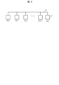
- an edge network that connects an ECU to sensors and actuators is configured to be connected to each communication terminal 11 (hereinafter referred to as a node) via a bus network 10.
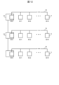
- a different identification number (ID number) is set to each node 11, and as shown in FIG. 1, each node 11 is designated as ID:0, ID:1, ID:2, ..., ID:N.
- ID:0 the identification number
- ID:0 the identification number assigned to each node 11
- ID:0 the node with ID:0 has the authority to transmit data as a coordinator node of the PLCA and manages data communication in the bus network 10. Therefore, when a PLCA bus cycle is started, the node 11 with ID:0 is given the authority to transmit to each node 11 in the order of the ID numbers set, and the node 11 transmits data only during the time when it has the authority to transmit.
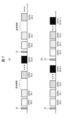
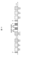
- node 11 with ID:0 transmits a beacon signal (transmission cycle start signal 12) to the bus network 10, which is the start of a PLCA cycle, thereby starting a communication period. Then, node 11 with ID:0 transfers the transmission authority to node 11 with the next ID number, ID:1. The time during which the transmission authority is delegated is silence time 12a. Node 11 with ID:1 that has the transmission authority transmits data and then delegates the transmission authority to the next node 11. This transfer of transmission authority is repeated until the transmission authority has been delegated down to node 11 with the last ID number, and one PLCA bus cycle is completed.
- a beacon signal transmission cycle start signal 12
- a node 11 Whenever a node 11 does not have transmission authority, it is in a receiving state and monitors the data on the bus network 10. In other words, even if it has data to send and no data from other communication terminals 11 is flowing on the network, it cannot transmit data unless it has transmission authority. If a node 11 that has transmission authority does not have data to transmit, it will transfer transmission authority to the node 11 with the next ID number after a certain period of time has passed.
- node 11 with ID:0 again transmits a beacon signal (transmission cycle start signal 12) to start the next PLCA cycle, thereby starting the next PLCA bus cycle.
- transmission authority is transferred between nodes, limiting the nodes that can transmit, thereby avoiding collisions between transmitted data.
- Figure 2 shows the control flow in the present invention in which the communication cycle setting unit automatically transitions to a setting mode that counts the number of nodes connected to each network so as not to leave any idle time during the communication cycle.
- the in-vehicle network system has an operation mode determination unit and a communication cycle setting unit, not shown.
- the operation mode determination unit determines the operation mode of data communication.
- the setting of the cycle of data communication in the bus network 10 is performed by the communication cycle setting unit.
- step S1 the operation mode determination unit determines whether to execute the communication mode. Based on this determination, the operation mode determination unit selects either a data communication mode in which data communication is performed from node 11 in the order determined by the identification number, or a setting mode in which the communication cycle setting unit sets the cycle.
- step S1 If it is determined in step S1 that the communication mode is to be executed (Yes), communication using the PLCA bus cycle is started in step S2. If it is determined in step S1 that the communication mode is not to be executed (No), normal Ethernet communication (CSMA/CD communication) is started in step S3, and a setting mode is started in which the control period of the beacon is set by the communication period setting unit.
- CSMA/CD communication normal Ethernet communication
- step S4 it is determined whether the target node 11 is the node 11 with ID: 0. If the node 11 is ID: 0 (Yes), the communication cycle setting unit checks the maximum ID value of the connected nodes 11 in the received frame in step S5, and sets the maximum ID value checked in step S6 to the node 11 with ID: 0 as the maximum number of nodes that can be connected. A cycle is set according to the maximum number of nodes calculated and set in this way, and communication using the PLCA bus cycle is started.
- step S8 If the target node 11 is not ID:0 in step S4, then in step S8 it transmits its own node ID number to the communication cycle setting unit.
- the communication cycle setting unit transmits the maximum ID value from among the received node ID numbers to node 11 with ID:0. This allows node 11 with ID:0 to check the ID values of each node 11 and confirm the number of nodes connected to the network, calculate and set the number of nodes based on the received ID numbers, and in step S9 starts communication via the PLCA bus cycle.
- the beacon control period is determined by the number of nodes connected to the network counted in the setting mode, and by matching it with the maximum number of nodes connected to the node with ID:0 to execute communication in the PLCA mode, a PLCA bus cycle can be realized that allows beacons to be transmitted at optimal timing.
- Figure 3(b) after data is transmitted from node 11 with ID:N and the silence time has elapsed and one cycle has ended, the idle time is shortened and the next transmission cycle start signal 12 can be received immediately.
- the communication cycle setting unit changes the ID number of the node (ID:N) whose ID number is set to the maximum value to ID:2, which is an empty number, and moves the node 11 with the changed ID to a node 11 with an empty number, thereby preventing the intrusion of malicious data.
- step S10 the operation mode determination unit determines whether or not to execute the communication mode. If it is determined that the communication mode is to be executed (Yes), communication using the PLCA bus cycle is started in step S11. If it is determined that the communication mode is not to be executed (No), normal Ethernet communication (CSMA/CD communication) is started in step S12, and the process moves to the setting mode of the communication cycle setting unit.
- CSMA/CD communication normal Ethernet communication
- step S13 it is determined whether the target node 11 has ID: 0. If the target node 11 has ID: 0 (Yes), the communication cycle setting unit checks the maximum value of the ID of the connected node 11, and in step S15 sets the maximum number of connected nodes to the node 11 with ID: 0.
- the communication cycle setting unit determines in step S16 whether there is a node with an empty ID in the order of nodes 11. If it determines that there is no node 11 with an empty ID number (Yes), communication begins using a PLCA bus cycle. If it determines that there is a node 11 with an empty ID (No), in step S18 the communication cycle setting unit requests the node 11 with the maximum ID value to change its ID number to an empty ID number. Once the node 11 with the maximum ID value has been changed to an empty ID number, step S16 is repeated to determine whether there is a node 11 with an empty ID.
- step S13 If it is determined in step S13 that the target node 11 does not have ID:0 (No), the ID of that node 11 is sent to the communication cycle setting unit, and the communication cycle setting unit sends the set node number to the node 11 with ID:0.
- step S20 the communication cycle setting unit determines whether there is a request to change the ID of the node 11. If there is no ID change request (Yes), the process moves directly to communication via the PLCA bus cycle in step S21. If there is an ID change request (No), the communication cycle setting unit changes the ID of the target node 11 in step S22, and moves to communication via the PLCA bus cycle in step S21.
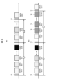
- the idle time in the communication cycle caused by the absence of node 11 with ID:2 can be filled by node 11 with ID:N changed to ID:2 as shown in FIG. 7(b), even if the maximum number of nodes set for node 11 with ID:0 is greater than the number of nodes connected to the bus network 10. This also makes it possible to achieve more efficient network bandwidth.
- the node 11 has a transmission data storage unit 17, a random data generation unit 18, a transmission data selection unit 20, and a data transmission unit 19.
- the data transmission unit 19 is connected to the bus network 10.
- the transmission data storage unit 17 stores the transmission data transmitted to the bus network 10.
- the random data generation unit 18 creates random data to be transmitted to the bus network 10.
- the transmission data selection unit 20 selects the data to be transmitted.
- the transmission data selection unit 20 obtains random data from the random data generation unit 18 and transmits the random data to the bus network 10 via the data transmission unit 19.
- node 11 with ID: 0 transmits information about the data free time (silence time) that occurs during the cycle to the communication cycle setting unit, and as shown in FIG. 9(b), the node 11 connected to the bus network 10 has the same setting for the time to transfer transmission authority after data transmission and the primary authority holding time for transferring transmission authority when there is no data to transmit, so that the beacon transmission cycle can always be constant, allowing the PLCA bus cycle to operate normally.
- Node 11 has a transmission data storage unit 17, a random data generation unit 18, a transmission data selection unit 20, and a data transmission unit 19. Furthermore, node 11 has a network data monitoring unit 21 and an available time measurement unit 22.
- the network data monitoring unit 21 monitors the communication status of the bus network 10.
- the idle time measurement unit 22 measures idle time (no data time) from the packet communication status in the bus network 10 via the network data monitoring unit 21.
- the idle time measurement unit 22 measures a specific idle time during a communication cycle, it outputs a command to the transmission data selection unit 20 to insert random data 14 into the cycle.
- a communication cycle starts with a transmission cycle start signal 12 and is filled with data for ID:0, ID:1, ID:2, ..., and ID:N-m.
- the free time measurement unit 22 measures that free time Ta has elapsed since the data for ID:N-m, it instructs the transmission data selection unit 20 to insert random data 14. If there is still free time for data until the next communication cycle, similarly, when the free time measurement unit 22 measures that free time Ta has elapsed, it instructs the transmission data selection unit 20 to insert random data 14, and repeats the transmission of random data to the bus network 10. In this way, it is possible to fill the free time until the next communication cycle and to keep the beacon cycle constant, thereby suppressing the intrusion of unauthorized data.
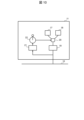
- the node 11 with ID: 0 in the edge network is a coordinator node that performs time management in a communication cycle. Therefore, by setting the node 11 with ID: 0 in the zone ECU 15 that is the connection between the backbone network 13 and the edge network, it becomes easier to find an abnormality, such as when the node 11 with ID: 0 breaks down and no longer transmits a beacon. In addition, since an error code or the like can be transmitted to the upper system without going through a bus connection, it becomes easier for the upper vehicle system to control the network, and communication reliability can be ensured.
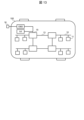
- the operation mode determination unit selects the setting mode only when the vehicle 100 is undergoing maintenance.
- the vehicle 100 is equipped with an OBD (On Board Diagnostics) device or the like used for vehicle maintenance, and when the setting mode changeover switch 16 is connected to the OBD device or the like from the outside, the operation mode determination unit selects the setting mode. Otherwise, the operation mode is always the PLCA mode. In this way, only specialists who inspect the system of the vehicle 100 can be given the authority to switch between the communication mode and the setting mode, and unauthorized access to the in-vehicle network system from others can be prevented.
- OBD On Board Diagnostics
- a vehicle-mounted network system includes a plurality of nodes 11, each of which is assigned a different identification number and connected to a bus 10, an operation mode determination unit that determines an operation mode for communication on the bus 10, and a communication cycle setting unit that sets the cycle of communication on the bus 10, and the operation mode determination unit selects either a data communication mode in which the nodes 11 communicate according to an order determined by the identification numbers, or a setting mode in which the communication cycle setting unit sets the cycle of communication, and when the operation mode determination unit selects the setting mode, the communication cycle setting unit calculates the number of nodes 11 connected to the bus 10 and sets the communication cycle according to the calculated number of nodes. In this way, an in-vehicle network system can be provided that achieves risk reduction by automatically optimizing the interval between beacons in each edge network.
- the nodes 11 transmit their assigned identification numbers to the communication cycle setting unit, and the communication cycle setting unit calculates the number of nodes based on the received identification numbers. In this way, the number of nodes set in the coordinator node can be made to match the number of nodes connected to the network.
- a coordinator node that manages communications is provided at the connection point 15 between the backbone network 13 and the edge network. This makes it easier to detect abnormalities and ensures communication reliability.
- the communication cycle setting unit changes the identification number of the node 11 with the largest identification number value to the available identification number. In this way, it is possible to fill the available time (time with no data) and achieve efficient network bandwidth.
- the device includes a random data generation unit 18 that generates random data 14 to be transmitted to the bus 10, a transmission data selection unit 20 that selects data to be transmitted to the bus 10, and a transmission data storage unit 17 that stores data transmitted to the bus 10.
- the transmission data selection unit 20 determines that there is data that is not stored in the transmission data storage unit 17, it obtains the random data 14 from the random data generation unit 18 and transmits the random data 14 to the bus 10. By doing this, the beacon transmission period can be always kept constant, allowing the PLCA bus cycle to operate normally.
- It has an idle time measurement unit 22 that determines whether there is a certain amount of idle time during the communication cycle, and when the idle time measurement unit 22 determines that there is a certain amount of idle time during the communication cycle, it outputs a command to the transmission data selection unit 20 to obtain random data from the random data generation unit 18 and transmit the random data to the bus 10. In this way, the beacon cycle can be made constant, thereby preventing the intrusion of unauthorized data.
- the operation mode determination unit selects the setting mode when the OBD device installed in the vehicle is being used. This prevents the general public from accessing the in-vehicle network system.
- the present invention is not limited to the above-described embodiment, and various modifications and other configurations can be combined without departing from the spirit of the invention. Furthermore, the present invention is not limited to those having all of the configurations described in the above-described embodiment, and also includes those in which some of the configurations have been omitted.
- Bus network 11 Communication terminal (node) 12 Transmission cycle start signal 12a Silence time 13 Backbone network 14 Random data 15 Zone ECU 16 Setting mode changeover switch 17 Transmission data storage unit 18 Random data generation unit 19 Data transmission unit 20 Transmission data selection unit 21 Network data monitoring unit 22 Free time measurement unit 100 Vehicle
Landscapes
- Small-Scale Networks (AREA)
- Engineering & Computer Science (AREA)
- Computer Networks & Wireless Communication (AREA)
- Signal Processing (AREA)
Abstract
車載ネットワークシステムは、それぞれ異なる識別番号が設定され、それぞれがバスに接続される複数のノードと、前記バスにおける通信の動作モードを決定する動作モード決定部と、前記バスにおける前記通信の周期を設定する通信周期設定部と、を備え、前記動作モード決定部は、前記識別番号に定められた順序に従って前記ノードによる前記通信を行うデータ通信モードか、前記通信周期設定部により前記通信の周期の設定を行う設定モードか、のいずれかを選択し、前記通信周期設定部は、前記動作モード決定部によって前記設定モードが選択された場合に、前記バスに接続された前記ノードのノード数を算出し、算出した前記ノード数に応じて前記通信の周期を設定する。
Description
本発明は、車載ネットワークシステムに関する。
近年、車両の自動運転においては、通常時には車両システムが運転制御や周囲監視を行い、緊急時には運転者が運転制御を行うことが想定されている。そのため、システムが故障を検知してから車両の制御を運転者へ移行するまでの時間は、システム側の安全性の確保が必須である。同時に、車両システムの高度化に伴い、装填されるセンサやアクチュエータ数は増加し、さらにシステムの自己診断等の機能が拡張しているため、車両システムを管理するCPUの処理能力が向上し、車両内で扱うデータ量が大幅に増加している。
大量のデータを扱う車載ネットワークには、標準的な規格としてイーサネット(登録商標)が導入され、ネットワークがドメインごとの1対1接続構造から1対Nの階層構造であるゾーンアーキテクチャに変化している。ゾーンアーキテクチャは、車両の走行制御を担う統合ECUと、ドメインに関係なく車両の場所ごとにセンサやアクチュエータの情報を集約するゾーンECUと、を有している。各センサやアクチュエータは、ゾーンECUを介して統合ECUと通信する構成で、ゾーンECU間と統合ECU間を接続する基幹ネットワークと、ゾーンECUとセンサやアクチュエータとを接続するエッジネットワークと、から構築されている。
エッジネットワークは、複数のセンサやアクチュエータを接続する必要があるが、ワイヤハーネス数を極力少なく抑えたいため、1本のバスに複数ノードを接続する構成で多くのセンサやアクチュエータと通信することができるバスネットワークが用いられる。これにより、リアルタイム性を確保できる。
しかしながら、1本のケーブルに複数の各ノードが接続されていることで、同時にデータを送信すると正常に通信できなくなることがある。例えば、イーサネット等では、データの衝突が発生した場合は、ランダムの時間分待ってから再送するため、通信データが増えるとさらに衝突する頻度が高くなり、重要なデータの送信遅延が発生する。そのため、特にリアルタイム通信が必須の車両制御では、各ノードがデータを送信するタイミングをずらして、データの衝突を回避してデータ消失を避けることができる、PLCA(Physical Layer Collision Avoidance)方式が採用されている。
例えば、下記の特許文献1では、送信権限をIDに基づき移譲するトークンパッシブ方式の通信で、各ノードで高優先イベント、周期信号、低優先イベントに分けて、各ノード内で次に送る周期の送信するデータを選択して送信する方式で、緊急データは、周期データよりも高優先で送信することができる技術が開示されている。この技術は、定期的に低優先イベントのデータを送信するタイミングも確保しており、この低優先イベントのデータを流すタイミングには、様々なデータを送信することができる。
特許文献1では、PLCA対応ノードと未対応ノードが共存可能であり、PLCA未対応のノードからもデータを送信することができることから、PLCA未対応の空き時間に通常のイーサネットのフレームを送信できてしまう。これにより、不正に接続されたノードから車両システムに侵入されるリスクがある。これを鑑みて本発明は、各エッジネットワークにおいて、自動的にビーコンの間隔を最適化することでリスク低減を実現した車載ネットワークシステムを提供することが目的である。
車載ネットワークシステムは、それぞれ異なる識別番号が設定され、それぞれがバスに接続される複数のノードと、前記バスにおける通信の動作モードを決定する動作モード決定部と、前記バスにおける前記通信の周期を設定する通信周期設定部と、を備え、前記動作モード決定部は、前記識別番号に定められた順序に従って前記ノードによる前記通信を行うデータ通信モードか、前記通信周期設定部により前記通信の周期の設定を行う設定モードか、のいずれかを選択し、前記通信周期設定部は、前記動作モード決定部によって前記設定モードが選択された場合に、前記バスに接続された前記ノードのノード数を算出し、算出した前記ノード数に応じて前記通信の周期を設定する。
本発明によれば、各エッジネットワークにおいて、自動的にビーコンの間隔を最適化することでリスク低減を実現した車載ネットワークシステムを提供できる。
以下、図面を参照して本発明の実施形態を説明する。以下の記載および図面は、本発明を説明するための例示であって、説明の明確化のため、適宜、省略および簡略化がなされている。本発明は、他の種々の形態でも実施する事が可能である。特に限定しない限り、各構成要素は単数でも複数でも構わない。
図面において示す各構成要素の位置、大きさ、形状、範囲などは、発明の理解を容易にするため、実際の位置、大きさ、形状、範囲などを表していない場合がある。このため、本発明は、必ずしも、図面に開示された位置、大きさ、形状、範囲などに限定されない。
(第1実施形態および全体構成)
(図1~図3)
車両において、ECUとセンサやアクチュエータとを接続するエッジネットワークは、バスネットワーク10を介して各通信端末11(以下ノード)と接続される構成を有している。PLCA方式では、各ノード11にはそれぞれ異なる識別番号(ID番号)が設定されており、図1に示すように、各ノード11にID:0、ID:1、ID:2…ID:Nと指定されている。バスネットワーク10に接続されるノード11のうち、ID:0の番号が設定されているノードのみがPLCAのコーディネータノードとしてデータの送信権限を有し、バスネットワーク10におけるデータ通信の管理をしている。そのため、PLCAバスサイクルが開始されると、ID:0のノード11から設定されたID番号の順番通りに各ノード11送信権限を与え、そのノード11が送信権限を有している時間のみデータを送信している。
図3(a)のデータ送信イメージに示すように、まず、ID:0のノード11が、PLCAサイクルの開始となるビーコン信号(送信サイクル開始信号12)をバスネットワーク10に送信することで、通信周期が開始される。そして、ID:0のノード11は、次のID番号を有するID:1のノード11に送信権限を移譲する。送信権限を委譲している時間はサイレンス時間12aである。送信権限を所持したID:1のノード11はデータを送信し、また次のノード11に送信権限を委譲する。このような送信権限の移譲を繰り返して、ID番号が最後のノード11まで送信権限が委譲されると、1周期分のPLCAバスサイクルが終了する。
ノード11が送信権限を所持していない時間は、全て受信状態となり、バスネットワーク10上のデータを監視している。つまり、送信データを有していて他の通信端末11からのデータがネットワークに流れていない時でも、送信権限を有していない限りはデータを送信することができない。送信権限を所持しているノード11は、送信するデータが無い場合には、一定時間経過すると次のID番号を有するノード11に送信権限を移譲する。
PLCAサイクルが1周期終了した後、次のPLCAサイクルを開始するために、再びID:0のノード11がビーコン信号(送信サイクル開始信号12)を送信することで、次のPLCAバスサイクルが開始される。このように、PLCAバスサイクルでは、ノード間で送信権限を移譲しながら送信できるノードを限定して、送信データ同士の衝突を回避している。
PLCA方式では、実際にネットワークに接続されるノード数よりも、ID番号が設定されているノード数が多いと、図3(a)のようにネットワークに空き時間(無データ時間)が増えてしまい、PLCA未対応のノードに送信機会を与えてしまう。つまり、PLCA対応ノードと未対応ノードとが共存できるようになっていることにより、空き時間ができることで、外部からのデータイーサによるウイルス等のネットワークへのデータの侵入を許してしまう。特に、車両において通常よりもセンサが少ない場合は、侵入の余地がある。これにより、悪意のあるノードが大量のデータを送信し続ける可能性があり、例えば、他のノードにデータ送信する機会を与えずにネットワークを占有して車両全体のネッワークを逼迫させることで、通常の車両制御データを送信できなくしたり、ウイルス等を侵入させて車両の制御を妨害したりする可能性が生じる。
よって、接続されたIDの最後のノードの送信が終了したら、すぐに次のPLCAバスサイクルを開始するビーコン信号を送信し、図3(a)に示したような空き時間を設けないようにする必要がある。これを実現するために、PLCAバスサイクルを開始するID:0のノード11のビーコン信号を送信するタイミングが接続されるノード数に依存するため、ID:0のノード11に対してデータを送信しているノード数を設定する必要がある。
以上の対策について、図2に、本発明において通信周期設定部が通信周期中の空き時間を設けないように、各ネットワークに接続されるノード数をカウントする設定モードに自動的に移行する制御フローを説明する。
バスネットワーク10において、車載ネットワークシステムは図示しない動作モード決定部および通信周期設定部を有している。動作モード決定部は、データ通信の動作モードを決定する。バスネットワーク10におけるデータ通信の周期の設定は、通信周期設定部によって実行される。
まず、ステップS1において、動作モード決定部は、通信モードを実行するかどうかを判断する。この判断により、動作モード決定部は、識別番号に定められた順序でノード11からデータ通信を行うデータ通信モードか、通信周期設定部によって周期の設定を行う設定モードか、を選択する。
ステップS1で通信モードを実行する(Yes)と判断した場合は、ステップS2でPLCAバスサイクルによる通信を開始する。ステップS1で通信モードを実行しない(No)と判断した場合は、ステップS3で、通常のイーサネットによる通信(CSMA/CD通信)を開始し、通信周期設定部によってビーコンの制御周期が設定される設定モードが起動する。
次に、ステップS4では、対象のノード11に対してID:0のノード11であるかどうかを判断する。そのノード11がID:0(Yes)である場合は、通信周期設定部は、ステップS5で受信フレームの中で接続されているノード11のID値の最大値を確認して、ステップS6で確認したID値の最大値を接続される最大ノード数としてID:0であるノード11に設定する。このように算出して設定した最大ノード数に応じて周期を設定して、PLCAバスサイクルによる通信を開始する。
ステップS4で対象のノード11がID:0でない場合は、ステップS8で自らのノードのID番号を通信周期設定部に送信する。通信周期設定部は受信したノードのID番号の中から、最大値となるID値をID:0のノード11に対して送信する。これにより、ID:0のノード11は、各ノード11のID値を確認してネットワークに接続されているノード数を確認でき、受信したID番号に基づいてノード数を算出して設定して、ステップS9でPLCAバスサイクルによる通信を開始する。
以上のような制御フローを実行することにより、これにより、設定モードでカウントしたネットワークに接続されているノード数によりビーコンの制御周期を決定し、ID:0のノードに接続される最大ノード数と一致させてPLCAモードでも通信を実行することで、ビーコンを最適なタイミングで送信できるようになるPLCAバスサイクルを実現できる。図3(b)に示すように、ID:Nのノード11からデータを送信して、サイレンス時間が経過して1サイクルが終了した後に、空き時間を短くしてすぐ次の送信サイクル開始信号12を受信できる。
このようにすることで、PLCA未対応の悪意のあるノードがネットワークに接続したとしても、データ送信の機会を与えずに車両システムへの妨害を防ぐため、車両の安全性を確保できる。
(第2実施形態)
(図4~図7)
ID:0にバスネットワーク10によって接続される複数のノード11のうち、ノードの識別番号の順序において空きIDのノードができる場合があり、例えば図4に図示するようにID:2のノード11がないと、図7(a)のデータ送信イメージに示すように空き時間(無データ時間)ができてしまい、この部分にPLCA未対応のノードから不正なデータを受信するリスクが生じる。この場合、図6に示すように通信周期設定部が、ID番号が最大値に設定されているノード(ID:N)のID番号を、空き番号であるID:2に変更して、IDを変更したノード11を空きのあるノード11に動かすことで、悪意あるデータの侵入を抑制することができる。
図5に第2実施形態の制御フローを示す。まずステップS10で、動作モード決定部が通信モードを実行するかどうかを判定する。通信モードを実行する(Yes)と判断した場合は、そのままステップS11でPLCAバスサイクルによる通信を開始する。通信モードを実行しない(No)と判断した場合は、ステップS12で通常のイーサネットによる通信(CSMA/CD通信)を開始し、通信周期設定部の設定モードに移行する。
次に、ステップS13で、対象のノード11がID:0であるかどうかを判定する。対象のノード11がID:0(Yes)である場合は、通信周期設定部は接続されているノード11のIDの最大値を確認し、ステップS15で接続される最大ノード数をID:0のノード11に設定する。
ID:0のノード11に最大ノード数を設定した後は、通信周期設定部はステップS16でノード11の順序に空きIDのノードがないかどうかを判断する。空きID番号のノード11がないと判断(Yes)した場合は、PLCAバスサイクルによる通信を開始する。空きIDのノード11がある(No)と判断した場合は、ステップS18で通信周期設定部は最大ID値を有するノード11に対して、ID番号を空きID番号に変更する要求を行う。最大ID値を有するノード11が空きID番号に変更されると、再び空きIDのノード11がないかどうかを判断するステップS16を繰り返す。
ステップS13において、対象のノード11がID:0でない(No)と判断した場合は、そのノード11のIDを通信周期設定部に送信し、通信周期設定部がID:0のノード11に設定ノード数を送信する。ステップS20で、通信周期設定部はノード11のIDの変更要求がないかどうかを判断する。ID変更要求がない(Yes)場合は、そのままステップS21でPLCAバスサイクルによる通信へ移行する。ID変更要求がある(No)場合は、通信周期設定部はステップS22で対象のノード11のIDを変更して、ステップS21のPLCAバスサイクルによる通信へ移行する。
このような設定を行うことで、図7(a)に示すように、ID:2のノード11がないことによる通信周期の空き時間が、図7(b)に示すように、ID:NをID:2に変更したノード11が代替することによって、ID:0のノード11に設定される最大ノード数がバスネットワーク10に接続されるノード数よりも多い場合であっても、通信周期の空き時間を埋めることができる。また、ネットワーク帯域の効率化を実現できる。
(第3実施形態)
(図8、図9)
前述した図7(a)に示すように、空き時間ができた場合、空いているノード11にはデータ(パケット)がないため、そのノード11の通信を飛ばして次の通信に権限移譲していくが、これにより、図9(a)に示すように全体の送信周期がずれる。そこで本実施形態では、ビーコンの周期を一定にするために、空き時間にランダムにデータを送信して送信周期のずれを解消する。
(図8、図9)
前述した図7(a)に示すように、空き時間ができた場合、空いているノード11にはデータ(パケット)がないため、そのノード11の通信を飛ばして次の通信に権限移譲していくが、これにより、図9(a)に示すように全体の送信周期がずれる。そこで本実施形態では、ビーコンの周期を一定にするために、空き時間にランダムにデータを送信して送信周期のずれを解消する。
ノード11は、送信データ記憶部17、ランダムデータ生成部18、送信データ選択部20、データ送信部19を有する。データ送信部19はバスネットワーク10に接続されている。送信データ記憶部17は、バスネットワーク10に送信した送信データを記憶している。ランダムデータ生成部18は、バスネットワーク10に送信するランダムデータを作成する。送信データ選択部20は、送信するデータを選択している。
送信データ選択部20は、送信データ記憶部17に記憶されていないデータがある場合、ランダムデータ生成部18からランダムデータを取得して、データ送信部19を介してバスネットワーク10にそのランダムデータを送信する。
このようにすることで、動作モード決定部で設定モードが選択されたときに、ID:0のノード11から通信周期設定部に対して、周期中に発生するデータの空き時間(サイレンス時間)の情報が送信され、図9(b)に示すように、バスネットワーク10に接続されるノード11は、データ送信後の送信権限の移譲する時間と、送信するデータが無い場合に送信権限の移譲するための一次権限保有時間とが、同一の設定にされて、ビーコンの送信周期を常に一定にすることができるため、PLCAバスサイクルを正常に動作させることができる。
(第4実施形態)
(図10、図11)
ID:0のノード11に設定される最大ノード数がネットワークノード数よりも多い場合には、周期に空き時間があるため、不正データの侵入の可能性がある。そこで、周期中に所定のデータの空き時間があるかどうかを判断し、所定の時間以上のデータ(パケット)がないと判断される場合に、ランダムデータ14で埋めている対応策を取る。
(図10、図11)
ID:0のノード11に設定される最大ノード数がネットワークノード数よりも多い場合には、周期に空き時間があるため、不正データの侵入の可能性がある。そこで、周期中に所定のデータの空き時間があるかどうかを判断し、所定の時間以上のデータ(パケット)がないと判断される場合に、ランダムデータ14で埋めている対応策を取る。
ノード11は、送信データ記憶部17、ランダムデータ生成部18、送信データ選択部20、データ送信部19を有する。さらに、ノード11は、ネットワークデータ監視部21、空き時間計測部22を有する。
ネットワークデータ監視部21は、バスネットワーク10の通信状況を監視している。空き時間計測部22は、ネットワークデータ監視部21を介して、バスネットワーク10におけるパケットの通信状況から空き時間(無データ時間)の計測を行っている。空き時間計測部22は、通信周期中の所定の空き時間を計測すると、送信データ選択部20に対して、ランダムデータ14を周期に挿入する指令を出力する。
図11のデータ送信イメージに示すように、通信周期において、送信サイクル開始信号12から始まり、ID:0のデータ、ID:1のデータ、ID:2のデータ…ID:N-mのデータと埋まっているが、ID:0のノード11に設定される最大ノード数がネットワークノード数よりも多い場合には、またデータの空き時間がある。そこで、空き時間計測部22は、ID:N-mのデータから空き時間Ta分の時間が経過したことを計測したら、送信データ選択部20に対してランダムデータ14を挿入するように指令を行う。次の通信周期までの間にデータの空き時間がまだ存在する場合は、同様に空き時間計測部22が空き時間Ta分の時間が経過したことを計測したら、送信データ選択部20に対してランダムデータ14を挿入するように指令を行い、バスネットワーク10にランダムデータを送信することを繰り返す。このようにすることで、次の通信周期までの空き時間を埋めることができ、ビーコンの周期を一定にすることができるため、不正なデータの侵入を抑制できる。
(第5実施形態)
(図12)
PLCA方式による通信において、エッジネットワークのID:0のノード11は、通信周期における時間管理等を行うコーディネータノードである。そのため、ID:0のノード11は、基幹ネットワーク13とエッジネットワークとの接続部であるゾーンECU15内に設定されることで、例えばID:0のノード11が故障してビーコンが出なくなるなどの異常を発見しやすくできる。また、エラーコード等はバス接続を介さずに上位システムに送信することができるため、上位の車両システムによるネットワークの制御が容易になり、通信信頼性を確保できる。
(図12)
PLCA方式による通信において、エッジネットワークのID:0のノード11は、通信周期における時間管理等を行うコーディネータノードである。そのため、ID:0のノード11は、基幹ネットワーク13とエッジネットワークとの接続部であるゾーンECU15内に設定されることで、例えばID:0のノード11が故障してビーコンが出なくなるなどの異常を発見しやすくできる。また、エラーコード等はバス接続を介さずに上位システムに送信することができるため、上位の車両システムによるネットワークの制御が容易になり、通信信頼性を確保できる。
(第6実施形態)
(図13)
動作モード決定部は、車両100のメンテナンスの時のみに設定モードを選択する。具体的には、例えば車両100には車両メンテナンスに用いられるOBD(On Board Diagnostics)装置等が搭載されており、このOBD装置等に対して設定モード切替えスイッチ16が外部から接続されるときに、動作モード決定部が設定モードを選択する。これ以外の場合は常にPLCAモードである。このようにすることで、車両100のシステム点検の専門業者だけに、通信モードと設定モードの切り替えを行う権限を付与することができ、それ以外からの車載ネットワークシステムへの不正なアクセスを防止できる。
(図13)
動作モード決定部は、車両100のメンテナンスの時のみに設定モードを選択する。具体的には、例えば車両100には車両メンテナンスに用いられるOBD(On Board Diagnostics)装置等が搭載されており、このOBD装置等に対して設定モード切替えスイッチ16が外部から接続されるときに、動作モード決定部が設定モードを選択する。これ以外の場合は常にPLCAモードである。このようにすることで、車両100のシステム点検の専門業者だけに、通信モードと設定モードの切り替えを行う権限を付与することができ、それ以外からの車載ネットワークシステムへの不正なアクセスを防止できる。
以上説明した本発明の実施形態によれば、以下の作用効果を奏する。
(1)それぞれ異なる識別番号が設定され、それぞれがバス10に接続される複数のノード11と、バス10における通信の動作モードを決定する動作モード決定部と、バス10における通信の周期を設定する通信周期設定部と、を備え、動作モード決定部は、識別番号に定められた順序に従ってノード11による通信を行うデータ通信モードか、通信周期設定部により通信の周期の設定を行う設定モードか、のいずれかを選択し、通信周期設定部は、動作モード決定部によって設定モードが選択された場合に、バス10に接続されたノード11のノード数を算出し、算出したノード数に応じて通信周期を設定する。このようにしたことで、各エッジネットワークにおいて、自動的にビーコンの間隔を最適化することでリスク低減を実現した車載ネットワークシステムを提供できる。
(2)複数のノード11は、動作モード決定部によって設定モードが選択された場合に、ノード11は自らに割り当てられた識別番号を通信周期設定部に送信し、通信周期設定部は、受信した識別番号に基づいてノード数を算出する。このようにしたことで、コーディネータノードに設定されるノード数とネットワークに接続されているノード数とを一致させることができる。
(3)複数のノード11のうち通信の管理をするコーディネータノードは、基幹ネットワーク13とエッジネットワークの接続部15に設けられる。このようにしたことで、異常を発見しやすくでき、通信信頼性を確保できる。
(4)動作モード決定部によって設定モードが選択された場合に、コーディネータノードから通信周期設定部に対して、通信の周期中に発生するデータの空き時間の情報が送信される。このようにしたことで、空き時間(無データ時間)を埋めるための対応を実施できる。
(5)通信周期設定部は、複数のノード11の識別番号の順序において、識別番号に空きがある場合、識別番号の値が最大であるノード11の識別番号を、空きのある識別番号に変更する。このようにすることで、空き時間(無データ時間)を埋めて、ネットワーク帯域の効率化を実現できる。
(6)バス10に送信するランダムデータ14を生成するランダムデータ生成部18と、バス10に送信するデータを選択する送信データ選択部20と、バス10に送信したデータを記憶する送信データ記憶部17と、を有し、送信データ選択部20は、送信データ記憶部17に記憶されていないデータがあると判断した場合、ランダムデータ生成部18からランダムデータ14を取得して、ランダムデータ14をバス10に送信する。このようにしたことで、ビーコンの送信周期を常に一定にすることができるため、PLCAバスサイクルを正常に動作させることができる。
(7)通信の周期中に所定の空き時間があるかどうかを判断する空き時間計測部22、を有し、空き時間計測部22は、通信の周期中に所定の空き時間があると判断した場合、送信データ選択部20に対して、ランダムデータ生成部18からランダムデータを取得して、ランダムデータをバス10に送信する指令を出力する。このようにしたことで、ビーコンの周期を一定にすることができるため、不正なデータの侵入を抑制できる。
(8)動作モード決定部は、車両に搭載されているOBD装置が使用されている場合に、設定モードを選択する。このようにしたことで、一般の人が車載ネットワークシステムに接触することを防止できる。
なお、本発明は上記の実施形態に限定されるものではなく、その要旨を逸脱しない範囲内で様々な変形や他の構成を組み合わせることができる。また本発明は、上記の実施形態で説明した全ての構成を備えるものに限定されず、その構成の一部を削除したものも含まれる。
10 バスネットワーク
11 通信端末(ノード)
12 送信サイクル開始信号
12a サイレンス時間
13 基幹ネットワーク
14 ランダムデータ
15 ゾーンECU
16 設定モード切替えスイッチ
17 送信データ記憶部
18 ランダムデータ生成部
19 データ送信部
20 送信データ選択部
21 ネットワークデータ監視部
22 空き時間計測部
100 車両
11 通信端末(ノード)
12 送信サイクル開始信号
12a サイレンス時間
13 基幹ネットワーク
14 ランダムデータ
15 ゾーンECU
16 設定モード切替えスイッチ
17 送信データ記憶部
18 ランダムデータ生成部
19 データ送信部
20 送信データ選択部
21 ネットワークデータ監視部
22 空き時間計測部
100 車両
Claims (8)
- それぞれ異なる識別番号が設定され、それぞれがバスに接続される複数のノードと、
前記バスにおける通信の動作モードを決定する動作モード決定部と、
前記バスにおける前記通信の周期を設定する通信周期設定部と、を備え、
前記動作モード決定部は、前記識別番号に定められた順序に従って前記ノードによる前記通信を行うデータ通信モードか、前記通信周期設定部により前記通信の周期の設定を行う設定モードか、のいずれかを選択し、
前記通信周期設定部は、前記動作モード決定部によって前記設定モードが選択された場合に、前記バスに接続された前記ノードのノード数を算出し、算出した前記ノード数に応じて前記通信の周期を設定する
車載ネットワークシステム。 - 請求項1に記載された車載ネットワークシステムであって、
前記複数のノードは、前記動作モード決定部によって前記設定モードが選択された場合に、前記ノードは自らに割り当てられた前記識別番号を前記通信周期設定部に送信し、
前記通信周期設定部は、受信した前記識別番号に基づいて前記ノード数を算出する
車載ネットワークシステム。 - 請求項1に記載された車載ネットワークシステムであって、
前記複数のノードのうち前記通信の管理をするコーディネータノードは、基幹ネットワークとエッジネットワークの接続部に設けられる
車載ネットワークシステム。 - 請求項3に記載された車載ネットワークシステムであって、
前記動作モード決定部によって前記設定モードが選択された場合に、前記コーディネータノードから前記通信周期設定部に対して、前記通信の周期中に発生するデータの空き時間の情報が送信される
車載ネットワークシステム。 - 請求項1に記載された車載ネットワークシステムであって、
前記通信周期設定部は、前記複数のノードの前記識別番号の前記順序において、前記識別番号に空きがある場合、前記識別番号の値が最大である前記ノードの前記識別番号を、空きのある前記識別番号に変更する
車載ネットワークシステム。 - 請求項1に記載された車載ネットワークシステムであって、
前記バスに送信するランダムデータを生成するランダムデータ生成部と、
前記バスに送信するデータを選択する送信データ選択部と、
前記バスに送信した前記データを記憶する送信データ記憶部と、を有し、
前記送信データ選択部は、前記送信データ記憶部に記憶されていない前記データがあると判断した場合、前記ランダムデータ生成部から前記ランダムデータを取得して、前記ランダムデータを前記バスに送信する
車載ネットワークシステム。 - 請求項6に記載された車載ネットワークシステムであって、
前記通信の周期中に所定の空き時間があるかどうかを判断する空き時間計測部、を有し、
前記空き時間計測部は、前記通信の周期中に所定の前記空き時間があると判断した場合、前記送信データ選択部に対して、前記ランダムデータ生成部から前記ランダムデータを取得して、前記ランダムデータを前記バスに送信する指令を出力する
車載ネットワークシステム。 - 請求項1に記載された車載ネットワークシステムであって、
前記動作モード決定部は、車両に搭載されているOBD装置が使用されている場合に、前記設定モードを選択する
車載ネットワークシステム。
Priority Applications (1)
| Application Number | Priority Date | Filing Date | Title |
|---|---|---|---|
| DE112024002529.3T DE112024002529T5 (de) | 2023-09-11 | 2024-08-26 | Fahrzeugnetzwerksystem |
Applications Claiming Priority (2)
| Application Number | Priority Date | Filing Date | Title |
|---|---|---|---|
| JP2023-146906 | 2023-09-11 | ||
| JP2023146906A JP2025040165A (ja) | 2023-09-11 | 2023-09-11 | 車載ネットワークシステム |
Publications (1)
| Publication Number | Publication Date |
|---|---|
| WO2025057713A1 true WO2025057713A1 (ja) | 2025-03-20 |
Family
ID=95022206
Family Applications (1)
| Application Number | Title | Priority Date | Filing Date |
|---|---|---|---|
| PCT/JP2024/030345 Ceased WO2025057713A1 (ja) | 2023-09-11 | 2024-08-26 | 車載ネットワークシステム |
Country Status (3)
| Country | Link |
|---|---|
| JP (1) | JP2025040165A (ja) |
| DE (1) | DE112024002529T5 (ja) |
| WO (1) | WO2025057713A1 (ja) |
Citations (5)
| Publication number | Priority date | Publication date | Assignee | Title |
|---|---|---|---|---|
| JPS63203037A (ja) * | 1987-02-19 | 1988-08-22 | Nippon Denso Co Ltd | ネツトワ−ク内のデ−タ伝送制御装置 |
| JP2001177542A (ja) * | 1999-12-17 | 2001-06-29 | Mitsubishi Electric Corp | 制御ノード間通信装置 |
| US20040146051A1 (en) * | 2002-11-22 | 2004-07-29 | Thomas Fuehrer | Method and device for transmitting data in messages on a bus system |
| JP2008504725A (ja) * | 2004-06-26 | 2008-02-14 | ローベルト ボッシュ ゲゼルシャフト ミット ベシュレンクテル ハフツング | バスシステムの制御方法、バスシステムの装置およびバスシステム |
| JP2009524308A (ja) * | 2006-01-20 | 2009-06-25 | ローベルト ボツシユ ゲゼルシヤフト ミツト ベシユレンクテル ハフツング | 動的リソース割当てのための方法及びシステム |
-
2023
- 2023-09-11 JP JP2023146906A patent/JP2025040165A/ja active Pending
-
2024
- 2024-08-26 DE DE112024002529.3T patent/DE112024002529T5/de active Pending
- 2024-08-26 WO PCT/JP2024/030345 patent/WO2025057713A1/ja not_active Ceased
Patent Citations (5)
| Publication number | Priority date | Publication date | Assignee | Title |
|---|---|---|---|---|
| JPS63203037A (ja) * | 1987-02-19 | 1988-08-22 | Nippon Denso Co Ltd | ネツトワ−ク内のデ−タ伝送制御装置 |
| JP2001177542A (ja) * | 1999-12-17 | 2001-06-29 | Mitsubishi Electric Corp | 制御ノード間通信装置 |
| US20040146051A1 (en) * | 2002-11-22 | 2004-07-29 | Thomas Fuehrer | Method and device for transmitting data in messages on a bus system |
| JP2008504725A (ja) * | 2004-06-26 | 2008-02-14 | ローベルト ボッシュ ゲゼルシャフト ミット ベシュレンクテル ハフツング | バスシステムの制御方法、バスシステムの装置およびバスシステム |
| JP2009524308A (ja) * | 2006-01-20 | 2009-06-25 | ローベルト ボツシユ ゲゼルシヤフト ミツト ベシユレンクテル ハフツング | 動的リソース割当てのための方法及びシステム |
Also Published As
| Publication number | Publication date |
|---|---|
| DE112024002529T5 (de) | 2026-05-21 |
| JP2025040165A (ja) | 2025-03-24 |
Similar Documents
| Publication | Publication Date | Title |
|---|---|---|
| US8448035B2 (en) | Communication system adapting for car, communication apparatus adapting for car, and communication method adapting for car | |
| EP1022878B1 (en) | Data transmission system | |
| US20080304499A1 (en) | Gateway device, network system and data converting method applied to vehicle using plurality of network protocol different from each other | |
| US20080306647A1 (en) | In-vehicle network system and control method thereof | |
| CN111108725A (zh) | 用于监视通信总线上的通信的方法和用于连接到通信总线的电子设备 | |
| EP0449304A2 (en) | Multiplex transmission system for use in vehicles | |
| CN112398901A (zh) | 执行双报文仲裁的方法和系统 | |
| KR20100020253A (ko) | 차량 네트워크에서의 메시지 전송 상태 진단 장치 | |
| KR950005114B1 (ko) | 버스방식으로 구성된 구내정보통신망의 통신로접속방법 | |
| JP3303469B2 (ja) | 多重伝送システム | |
| JP3770053B2 (ja) | 車両用ネットワークの通信復帰判定方法 | |
| JP2020022019A (ja) | 車両システム | |
| JPH04298136A (ja) | 多重伝送方法 | |
| JP2008535347A (ja) | 制御装置と少なくとも1つの分散型データ処理装置との間のデータ線路でデータを伝送する方法および装置 | |
| US10686623B2 (en) | System and method for dynamic bi-directional communication over a local interconnect network bus | |
| JP2002359625A (ja) | コントロールエリアネットワーク | |
| JP2025040165A (ja) | 車載ネットワークシステム | |
| CN118555163B (zh) | 一种通信方法、第一节点、第二节点、架构、车辆及介质 | |
| CN111788800B (zh) | 帧传送方法以及安全星型耦合器 | |
| JP2005277896A (ja) | 車載ネットワーク拡張装置及び車載電子制御ユニット | |
| JP5099755B2 (ja) | 通信方法、通信システム及び通信装置 | |
| US5272699A (en) | Method of multiplex transmission | |
| JP7151930B2 (ja) | 中継装置、通信ネットワークシステム及び通信制御方法 | |
| JP2010095134A (ja) | 通信中継装置 | |
| JP4361540B2 (ja) | ゲートウェイ装置、データ転送方法及びプログラム |
Legal Events
| Date | Code | Title | Description |
|---|---|---|---|
| 121 | Ep: the epo has been informed by wipo that ep was designated in this application |
Ref document number: 24865217 Country of ref document: EP Kind code of ref document: A1 |
|
| DPE1 | Request for preliminary examination filed after expiration of 19th month from priority date (pct application filed from 20040101) | ||
| WWE | Wipo information: entry into national phase |
Ref document number: 112024002529 Country of ref document: DE |
|
| WWP | Wipo information: published in national office |
Ref document number: 112024002529 Country of ref document: DE |