WO2025057331A1 - 光ファイバユニット、光ファイバケーブルおよび光ファイバユニットの製造方法 - Google Patents
光ファイバユニット、光ファイバケーブルおよび光ファイバユニットの製造方法 Download PDFInfo
- Publication number
- WO2025057331A1 WO2025057331A1 PCT/JP2023/033384 JP2023033384W WO2025057331A1 WO 2025057331 A1 WO2025057331 A1 WO 2025057331A1 JP 2023033384 W JP2023033384 W JP 2023033384W WO 2025057331 A1 WO2025057331 A1 WO 2025057331A1
- Authority
- WO
- WIPO (PCT)
- Prior art keywords
- optical fiber
- inner layer
- fiber unit
- cable
- cores
- Prior art date
- Legal status (The legal status is an assumption and is not a legal conclusion. Google has not performed a legal analysis and makes no representation as to the accuracy of the status listed.)
- Pending
Links
Images


Classifications
-
- G—PHYSICS
- G02—OPTICS
- G02B—OPTICAL ELEMENTS, SYSTEMS OR APPARATUS
- G02B6/00—Light guides; Structural details of arrangements comprising light guides and other optical elements, e.g. couplings
- G02B6/02—Optical fibres with cladding with or without a coating
-
- G—PHYSICS
- G02—OPTICS
- G02B—OPTICAL ELEMENTS, SYSTEMS OR APPARATUS
- G02B6/00—Light guides; Structural details of arrangements comprising light guides and other optical elements, e.g. couplings
- G02B6/44—Mechanical structures for providing tensile strength and external protection for fibres, e.g. optical transmission cables
Definitions
- This disclosure relates to an optical fiber unit, an optical fiber cable, and a method for manufacturing an optical fiber unit.
- Patent Document 1 discloses an optical fiber unit having an optical fiber tape core wire that includes multiple optical fiber core wires and a tape resin that integrates the multiple optical fiber core wires in a parallel state, and a coating resin that covers the optical fiber tape core wires in an assembled form.
- An optical fiber unit includes: A plurality of optical fiber cores each having an outer diameter of 200 ⁇ m or less; an inner layer in contact with the plurality of optical fiber cores and covering the plurality of optical fiber cores; an outer layer disposed outside the inner layer,
- the optical fiber core wires are integrated by being covered with the inner layer in a bundled state,
- the outer shape of the optical fiber unit is circular,
- the inner layer has a lower Young's modulus than the outer layer.
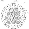
- FIG. 1 is a cross-sectional view of an optical fiber unit according to the present embodiment.
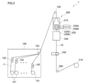
- FIG. 2 is a schematic diagram of the optical fiber unit manufacturing apparatus according to the present embodiment.
- FIG. 3 is a flow chart illustrating a method for manufacturing an optical fiber unit according to this embodiment.
- FIG. 4 is a cross-sectional view of a fiber optic cable comprising six fiber optic units.
- FIG. 5 is a cross-sectional view of a fiber optic cable comprising 24 optical fiber units.
- an optical fiber cable having an optical fiber ribbon including a plurality of optical fiber core wires each having an outer diameter of 200 ⁇ m or less it may be difficult to remove the coating of the optical fiber ribbon all at once or to perform fusion splicing.
- the optical fiber core wire may break during the manufacturing process of the optical fiber cable.
- a plurality of optical fiber core wires are unitized, there is a need to improve the lateral pressure resistance and external damage resistance of the optical fiber unit and the core wire removal property of the optical fiber core wire.
- the present disclosure aims to provide an optical fiber unit, optical fiber cable, and method of manufacturing an optical fiber unit that can suppress breakage of the optical fiber core while using a thin-diameter optical fiber core, and that has good resistance to lateral pressure and external damage of the optical fiber unit and good core removal performance of the optical fiber core.
- An optical fiber unit includes: (1) A plurality of optical fiber cores each having an outer diameter of 200 ⁇ m or less; an inner layer in contact with the plurality of optical fiber cores and covering the plurality of optical fiber cores; an outer layer disposed outside the inner layer, The optical fiber core wires are integrated by being covered with the inner layer in a bundled state, In a cross-sectional view of the optical fiber unit, the outer shape of the optical fiber unit is circular, The inner layer has a lower Young's modulus than the outer layer.
- the optical fiber unit which has a circular outer shape in a cross-sectional view, includes a plurality of optical fiber cores having an outer diameter of 200 ⁇ m or less, an inner layer covering the optical fiber cores, and an outer layer disposed outside the inner layer.
- the optical fiber cores included in the optical fiber unit are small-diameter optical fiber cores having an outer diameter of 200 ⁇ m or less, so the outer diameter of such an optical fiber unit is relatively small.
- the optical fiber cores are integrated by being covered by the inner layer in a bundled state, so they are unlikely to break.
- the optical fiber unit has a two-layer structure of an inner layer and an outer layer, and the Young's modulus of the inner layer is lower than that of the outer layer, the optical fiber unit according to the above configuration has high resistance to lateral pressure and resistance to external damage.
- the Young's modulus of the inner layer covering the optical fiber cores is lower than that of the outer layer, the optical fiber unit according to the above configuration has good core wire removal properties of the optical fiber cores. Therefore, with the optical fiber unit having the above configuration, even when a thin-diameter optical fiber core is used, breakage of the optical fiber core can be suppressed, and the optical fiber unit can have good resistance to lateral pressure and external damage, as well as good core removal ability of the optical fiber core.
- the inner layer may contain a lubricant. According to this configuration, since a lubricant is added to the inner layer, the optical fiber can be more easily removed.
- the outer diameter of the optical fiber may be less than 180 ⁇ m. According to this configuration, since such an optical fiber core is an extremely small diameter optical fiber core, the outer diameter of the optical fiber unit can be made small.
- the optical fiber included in the optical fiber core may be a multi-core fiber. With this configuration, the core density of the optical fiber unit can be increased.
- the inner layer may have a Young's modulus of 300 MPa or less. According to this configuration, the lateral pressure resistance can be improved.
- the outer layer may be a colored layer to which a pigment is added. This configuration makes it possible to improve the identification of the optical fiber unit.
- An optical fiber cable includes: (7) A plurality of optical fiber units according to any one of (1) to (6) above; and a cable jacket covering the plurality of optical fiber units.
- the outer diameter of such an optical fiber cable is relatively small.
- the optical fiber unit has good resistance to lateral pressure and external damage, and the optical fiber core wire is easy to remove.
- a strength member is further provided at the center of the optical fiber cable.
- a plurality of the optical fiber units may be disposed in a region formed between the strength member and the cable jacket. According to this configuration, since the multiple optical fiber units are disposed in the region formed between the tension member and the cable jacket, it is possible to provide a configuration including a relatively large number of optical fiber cables while keeping the outer diameter small. According to the optical fiber cable according to the above configuration, it is possible to increase the core density of the optical fiber cable while keeping the outer diameter small.
- the optical fiber cable according to (7) above, The optical fiber cable further includes a tension member disposed at a center thereof, and a water-absorbing tape disposed between the tension member and the cable jacket, The optical fiber unit may be arranged in each of a first region formed between the tensile member and the absorbent tape and a second region formed between the cable jacket and the absorbent tape. According to this configuration, since the optical fiber units are disposed in both the first region and the second region, the core density of the optical fiber cable can be increased while keeping the outer diameter relatively small.
- a core density obtained by dividing the number of cores contained in the coated optical fiber by a cross-sectional area of the optical fiber cable may be 10 cores/ mm2 or more. According to this configuration, by using the optical fiber unit, it is possible to increase the core density of the optical fiber cable while suppressing breakage of the optical fiber core.
- a method for producing an optical fiber unit includes the steps of: (11) A step of collecting a plurality of optical fiber cores having an outer diameter of 200 ⁇ m or less; passing a plurality of the optical fibers through a die; a step of covering the plurality of optical fiber core wires bundled in the die with a first resin material and covering the first resin material with a second resin material; forming an inner layer covering the plurality of optical fiber cores by irradiating the first resin material with ultraviolet light to harden the first resin material, and forming an outer layer covering the inner layer by irradiating the second resin material with ultraviolet light to harden the second resin material, The optical fibers are in contact with the inner layer.
- an optical fiber unit in a cross-sectional view of an optical fiber unit including a plurality of the optical fiber cores, the inner layer, and the outer layer, the outer shape of the optical fiber unit is circular,
- the inner layer has a lower Young's modulus than the outer layer.
- an optical fiber unit can be manufactured that includes a plurality of optical fiber cores having an outer diameter of 200 ⁇ m or less, an inner layer covering the optical fiber cores, and an outer layer covering the inner layer, and has a circular outer shape in cross section.
- the optical fiber cores included in the fiber unit are small-diameter optical fiber cores having an outer diameter of 200 ⁇ m or less, so the outer diameter of such an optical fiber unit is relatively small.
- the optical fiber cores are covered with an inner layer having a circular outer shape in cross section formed by hardening the first resin material.
- the optical fiber cores are integrated in a bundled state by being covered with an inner layer having a circular outer shape in cross section, so that they are unlikely to break.
- the fiber unit has a two-layer structure of an inner layer and an outer layer, and the Young's modulus of the inner layer is lower than that of the outer layer, so that the optical fiber unit has high resistance to lateral pressure and resistance to external damage.
- the Young's modulus of the inner layer covering the optical fiber is lower than that of the outer layer, the optical fiber can be easily removed. Therefore, the optical fiber unit according to the above configuration can suppress breakage of the optical fiber even when a small-diameter optical fiber is used, and can improve the lateral pressure resistance and external damage resistance of the optical fiber unit and the ease of removing the optical fiber.
- an optical fiber unit an optical fiber cable, and a method for manufacturing an optical fiber unit that can suppress breakage of the optical fiber core while using a thin-diameter optical fiber core, and that has good resistance to lateral pressure and external damage and good core removal performance of the optical fiber core.
- Fig. 1 is a cross-sectional view of the optical fiber unit 10 according to the present embodiment.
- the optical fiber unit 10 includes a plurality of optical fiber cores 11, an inner layer 12 that covers the plurality of optical fiber cores 11, and an outer layer 13 that is disposed outside the inner layer 12.
- the outer diameter of the optical fiber core 11 is 200 ⁇ m or less, and preferably less than 180 ⁇ m.
- the outer diameter of the optical fiber core 11 is, for example, 160 ⁇ m.
- the optical fiber core 11 includes an optical fiber 110 including four cores 111 and a cladding 112, and a protective coating 113 that covers the optical fiber 110. Therefore, the optical fiber 110 included in the optical fiber core 11 is a multi-core fiber (MCF: Multi Core Fiber).
- MCF Multi Core Fiber
- the optical fiber 110 is, for example, a glass fiber in which the core 111 and the cladding 112 are formed of quartz glass.
- the core 111 is circular in radial cross section.
- the refractive index of the core 111 is higher than the refractive index of the cladding 112.
- the outer diameter of the core 111 is, for example, 5 ⁇ m or more and 10 ⁇ m or less.
- the clad 112 is arranged to integrally surround the four cores 111.
- the outer diameter of the clad 112 is larger than the outer diameter of the cores 111.
- the outer diameter of the clad 112 is, for example, 80 ⁇ m or more and 125 ⁇ m or less.
- the protective coating 113 is formed, for example, from an acrylate resin.
- the protective coating 113 is provided so as to cover the periphery of the cladding 112.
- the optical fiber unit 10 includes, as an example, 12 optical fiber cores 11.
- the 12 optical fiber cores 11 are integrated in a bundled state by being covered with an inner layer 12 whose outer shape in a cross-sectional view is circular. Therefore, the outer shape in a cross-sectional view of the optical fiber unit 10 is circular.
- "circular" includes not only a perfect circle, but also an approximate circle.
- An approximate circle is, for example, an ellipse that is visually recognized as being close to a perfect circle.
- the outer diameter of the optical fiber unit 10 is, for example, 0.8 mm.
- the covering structure of the optical fiber unit 10 is a two-layer structure consisting of an inner layer 12 and an outer layer 13.
- the inner layer 12 covers the 12 optical fiber cores 11.
- the inner layer 12 is in contact with the 12 optical fiber cores 11.
- the inner layer 12 can be formed from a resin material such as a urethane acrylate resin.
- a lubricant is added to the inner layer 12.
- the lubricant is formed from, for example, silicone.
- the Young's modulus of the inner layer 12 is, for example, 300 MPa or less.
- the outer layer 13 is disposed outside the inner layer 12.
- the outer layer 13 can be formed from a resin material such as, for example, a urethane acrylate resin.
- the resin material contains a pigment of any color. Therefore, the outer layer 13 is a colored layer to which a pigment has been added.
- the Young's modulus of the outer layer 13 is, for example, 1000 MPa. Therefore, the Young's modulus of the inner layer 12 is lower than the Young's modulus of the outer layer 13.
- FIG. 2 is a schematic diagram of the manufacturing apparatus 1 for the optical fiber unit 10 according to this embodiment.
- the manufacturing apparatus 1 for the optical fiber unit 10 has a supply device 100.
- the supply device 100 is provided with 12 bobbins 101 corresponding to the number of fibers in the optical fiber unit 10, 12 dancer rollers 102, and a first guide roller 103.
- An optical fiber core 11 is wound around each of the bobbins 101.
- the optical fiber core 11 is unwound from each of the bobbins 101, the tension of each is adjusted by the dancer roller 102, and the optical fiber core 11 is arranged on a single arrangement surface when it passes through the first guide roller 103.
- the optical fiber core 11 is further collected by the guide roller 104 directly above and sent to the resin application device 200.
- the die 220 includes a first portion 220A and a second portion 220B.
- the first portion 220A is located closer to the point 210 than the second portion 220B. Therefore, the 12 optical fiber cores 11 are first sent to the first portion 220A and then sent to the second portion 220B.
- the first portion 220A applies a first resin material to the 12 optical fiber cores 11.
- the second portion 220B applies a second resin material to the 12 optical fiber cores 11 so as to cover the first resin material applied to the 12 optical fiber cores 11.
- the hole shape of the outlet of the first portion 220A and the second portion 220B is circular, and the resin material is applied around the 12 optical fiber cores 11 so that the cross-sectional outer shape is circular.
- the first resin material and the second resin material are, for example, ultraviolet-curing resin.
- the ultraviolet-curing resin is, for example, urethane acrylate resin.
- a lubricant such as silicone is added to the first resin material.
- the second resin material contains a pigment of any color.
- the first resin material is supplied, for example, from a first resin tank 230A.
- the second resin material is supplied, for example, from a second resin tank 230B.
- the first resin tank 230A and the second resin tank 230B are, for example, pressurized resin tanks.
- the 12 optical fiber cores 11 covered with the first resin material and the second resin material are sent to an ultraviolet irradiation device 240.
- ultraviolet rays are irradiated onto the first resin material and the second resin material.
- an inner layer 12 that covers the 12 optical fiber cores 11 is formed
- an outer layer 13 that covers the inner layer 12 is formed.
- the 12 optical fiber cores 11 are integrated by being covered by the inner layer 12 in a bundled state.
- an optical fiber unit 10 is formed that includes the 12 optical fiber cores 11, the inner layer 12 that covers the 12 optical fiber cores 11, and the outer layer 13 that is positioned outside the inner layer 12.
- the formed optical fiber unit 10 is sent to the marking device 250.
- the marking device 250 is, for example, a dispenser, an inkjet printer, or the like.
- a dispenser is a device that ejects liquid such as ink onto an object.
- the marking device 250 applies, for example, a band-shaped marking onto the optical fiber unit 10.
- the optical fiber unit 10 with markings applied is sent to a winding device 310 having a second guide roller 260 and a bobbin.
- the optical fiber unit 10 is wound around the bobbin via a guide. In this manner, the optical fiber unit 10 is manufactured.
- a method for manufacturing the optical fiber unit 10 will be described with reference to Fig. 3.
- twelve optical fiber core wires 11 reeled out from each of the bobbins 101 are collected by an upper guide roller 104 (STEP 01).
- the collected twelve optical fiber core wires 11 are sent to a resin coating device 200.
- the 12 optical fiber cores 11 sent to the resin application device 200 are arranged in the desired arrangement at point 210 and then threaded through the die 220 (STEP 02).
- the twelve optical fiber core wires 11 passed through the die 220 are bundled in the die 220 so that the cross-sectional shape is close to a circle, and are covered with a first resin material, and the first resin material is covered with a second resin material (STEP 03).
- the twelve optical fiber core wires 11 covered with the first resin material and the second resin material are sent to the ultraviolet irradiation device 240.
- the first resin material and the second resin material are irradiated with ultraviolet light by the ultraviolet irradiation device 240, forming an inner layer 12 that covers the 12 optical fiber cores 11, and an outer layer 13 that covers the inner layer 12 (STEP 04). As a result, the optical fiber unit 10 is formed.
- the optical fiber unit 10 described above is provided with only 12 optical fiber cores 11 with an outer diameter of 200 ⁇ m or less, an inner layer 12 covering the optical fiber cores 11, and an outer layer 13 arranged outside the inner layer 12, so that the outer diameter of the optical fiber unit 10 is relatively small. Also, unlike an optical fiber ribbon, the 12 optical fiber cores 11 are covered with the inner layer 12 in a bundled state so that the cross-sectional outer shape is close to a circle, so that the outer shape of the optical fiber unit 10 in the cross-sectional view is circular.
- the entire circumference of the 12 optical fiber cores 11 is covered with the inner layer 12, which has a relatively thick coating thickness, so that the 12 optical fiber cores 11 are less likely to break compared to a tape-shaped optical fiber ribbon that is usually used.
- the optical fiber unit 10 can suppress breakage of the optical fiber cores 11 while using a thin-diameter optical fiber core 11.
- the structure of the optical fiber unit 10 is a two-layer structure consisting of the inner layer 12 and the outer layer 13, the optical fiber unit 10 has high resistance to external damage.
- the Young's modulus of the inner layer 12 is lower than that of the outer layer 13, the optical fiber unit 10 has high resistance to lateral pressure.
- the optical fiber unit 10 since the Young's modulus of the inner layer 12 covering the optical fiber core is lower than that of the outer layer 13, the optical fiber unit 10 has good core wire removal properties for the optical fiber core 11. Therefore, according to the optical fiber unit 10, it is possible to suppress breakage of the optical fiber core 11 while reducing the outer diameter of the optical fiber unit 10, and it is possible to improve the lateral pressure resistance and damage resistance of the optical fiber unit 10 and the core wire removal properties of the optical fiber core 11.
- the outer diameter of the optical fiber core 11 is 160 ⁇ m. In other words, the outer diameter of the optical fiber core 11 is less than 180 ⁇ m. In other words, since the optical fiber core 11 provided in the optical fiber unit 10 is an optical fiber core with an extremely small diameter, the outer diameter of the optical fiber unit 10 can be made small.
- the core density of the optical fiber unit 10 can be increased.
- the core density of the optical fiber unit 10 refers to the number of cores per unit area of the optical fiber unit 10.
- the outer layer 13 is a colored layer to which a pigment has been added, which improves the distinguishability of the optical fiber unit 10.
- the inventors performed evaluations of the optical fiber units according to Experimental Examples 1 to 8 in Table 1 with respect to the fiber removal property, the lateral pressure resistance, and the damage resistance.
- the evaluation index for the fiber removal property is whether the optical fiber core wire inside the optical fiber unit can be removed by hand without using a tool such as a nipper.
- the fiber removal property was determined to be good (evaluation A) when the optical fiber core wire inside the optical fiber unit could be removed by hand.
- the fiber removal property was determined to be somewhat good (evaluation B) when some of the optical fiber core wires were removed using a tool such as a nipper.
- the fiber removal property was determined to be poor (evaluation C) when the optical fiber core wire inside the optical fiber unit could not be removed even using a tool such as a nipper.
- the evaluation index for the lateral pressure resistance is the degree of loss increase when a lateral pressure of 500 N is applied to the optical fiber unit with a 100 mm metal plate.
- the lateral pressure resistance was determined to be good (evaluation A) when the loss increase when 500 N is applied is less than 0.1 dB. When the loss increase when 500N is applied is 0.1 dB or more and less than 0.3 dB, the lateral pressure resistance is considered to be somewhat good (evaluation B).
- the evaluation index for the external damage resistance is whether or not the optical fiber core wire is broken during the process of manufacturing the optical fiber unit. When the optical fiber core wire is not broken during the process of manufacturing the optical fiber unit, the external damage resistance is considered to be good (evaluation A). When the optical fiber core wire is broken during the process of manufacturing the optical fiber unit, the external damage resistance is considered to be poor (evaluation C).
- the optical fiber units according to Experimental Examples 1 to 4 are single-layer type optical fiber units.
- the optical fiber units 10 according to Experimental Examples 5 to 8 are double-layer type optical fiber units.
- the core wire removal property was somewhat good (B rating), and the lateral pressure resistance and the external damage resistance were good (A rating).
- B rating the Young's modulus of the inner layer 12
- a rating the Young's modulus of the inner layer 12
- the Young's modulus of the inner layer 12 can be made different from that of the outer layer 13, so that, for example, by increasing the Young's modulus of the outer layer 13 while decreasing the Young's modulus of the inner layer 12, it is possible to improve the lateral pressure resistance and resistance to external damage while also improving the ease of extracting the core wire. Therefore, if you want to improve the ease of extracting the core wire, the lateral pressure resistance, and the resistance to external damage, the two-layer optical fiber unit 10 is more suitable than the single-layer optical fiber unit.
- a comparison of the optical fiber unit 10 according to Experimental Example 5 with the optical fiber unit according to Experimental Example 7 revealed that the addition of a lubricant to the inner layer 12 can further improve the ease of core wire removal.
- a comparison of the optical fiber units according to Experimental Examples 5 and 6 with the optical fiber unit according to Experimental Example 8 also revealed that the ease of core wire removal can be further improved by setting the Young's modulus of the inner layer 12 to 300 MPa or less.
- the optical fiber unit 10 described above has a Young's modulus of the inner layer 12 of 300 MPa or less, so it has high resistance to lateral pressure.
- the optical fiber cable 20 includes six optical fiber units 10, a tensile member 21, a water-absorbent fiber 22, a cable jacket 23, and a tear string 24. Therefore, the optical fiber cable 20 is a 72-core optical fiber cable.
- the outer diameter of the optical fiber cable 20 is, for example, 3.6 mm.
- the core density (number of cores per unit area) obtained by dividing the number of cores 111 included in the optical fiber core 11 by the cross-sectional area of the optical fiber cable 20 is 10 cores/ mm2 or more.
- the optical fiber cable 20 is produced, for example, by arranging six optical fiber units 10 in a ring shape around the tensile strength body 21, and extrusion coating the cable jacket 23 so as to cover the six optical fiber units 10. Therefore, the six optical fiber units 10 are arranged outside the tensile strength body 21, and are covered by the cable jacket 23. In other words, the six optical fiber units 10 are arranged in the region R1 formed between the tensile strength body 21 and the cable jacket 23.
- the tension member 21 is formed, for example, from fiber reinforced plastic (FRP).
- FRP fiber reinforced plastic
- fiber reinforced plastic include glass fiber reinforced plastic (GFRP), aramid fiber reinforced plastic (AFRP), etc.
- the tension member 21 is substantially circular in a cross-sectional view of the optical fiber cable 20.
- the outer diameter of the tension member 21 is, for example, 0.7 mm or more and 0.8 mm or less.
- the tension member 21 is located approximately in the center of the optical fiber cable 20 in a cross-sectional view of the optical fiber cable 20.
- the absorbent fiber 22 is, for example, plastic fiber coated with absorbent powder, or fiber itself that has absorbency.
- the absorbent fiber 22 is, for example, a linear member having an outer diameter of about 0.1 mm in a dry state.
- the absorbent fiber 22 is provided along the longitudinal direction of the optical fiber cable 20.
- the absorbent fiber 22 is disposed between the tensile member 21 and the cable jacket 23.
- the cable sheath 23 is formed from a resin material such as polyethylene resin or flame-retardant polyethylene resin.
- the Young's modulus of the cable sheath 23 at 23°C is relatively high, for example, 1500 MPa or more.
- the cable sheath 23 has low shrinkage, low friction, and flame retardancy.
- Identification marks such as numbers and letters may be printed on the cable sheath 23 using a laser printer or the like.
- the tear cord 24 is for tearing the cable sheath 23, and is embedded within the cable sheath 23 along the longitudinal direction of the optical fiber cable 20.
- two tear cords 24 are provided.
- the two tear cords 24 are arranged in opposing positions relative to the tensile member 21 in a cross-sectional view of the optical fiber cable 20.
- the tear cord 24 is formed, for example, from a plastic material (e.g., polyester) that is resistant to pulling.
- the optical fiber cable 20 as described above is manufactured using the optical fiber units 10 with a relatively small outer diameter, and therefore the outer diameter of the optical fiber cable 20 is relatively small. Furthermore, the optical fiber cable 20 as described above can prevent the optical fiber core wires 11 from breaking when the six optical fiber units 10 are covered with the cable jacket 23 to form a cable. Furthermore, in the optical fiber cable 20, the optical fiber units 10 provided in the optical fiber cable 20 have good resistance to lateral pressure and external damage, and the optical fiber core wires 11 are easy to remove.
- optical fiber cable 20 as described above, six optical fiber units 10 are arranged in the region R1 formed between the tensile member 21 and the cable jacket 23. Therefore, with the optical fiber cable 20, it is possible to have a configuration including a relatively large number of optical fiber units 10 while keeping the outer diameter small. In other words, with the optical fiber cable 20, it is possible to increase the core density of the optical fiber cable 20 while keeping the outer diameter small.
- the core density is 10 cores/ mm2 or more, and breakage of the optical fiber core 11 can be suppressed while increasing the core density of the optical fiber cable 20.
- the optical fiber cable 20A includes 24 optical fiber units 10, a tension member 21A, a cable jacket 23, a tear string 24, and a water-absorbing tape 25. Therefore, the optical fiber cable 20A is an optical fiber cable with 288 cores.
- the outer diameter of the optical fiber cable 20A is, for example, 6.0 mm.
- the core density of the optical fiber cable 20A is also 10 cores/ mm2 or more.
- the optical fiber cable 20A has a structure in which the optical fiber units 10 are housed in two layers.
- the single layer portion is produced by arranging eight optical fiber units 10 in a ring shape around the tensile strength member 21A at the center, and wrapping the water-absorbing tape 25 around the eight optical fiber units 10.
- the double layer portion is produced by arranging the remaining 16 optical fiber units 10 in a ring shape to cover the water-absorbing tape 25, and extrusion-coating the cable jacket 23 to cover the 16 optical fiber units 10. Therefore, eight optical fiber units 10 are arranged in the first region R11 formed between the tensile strength member 21A and the water-absorbing tape 25, and 16 optical fiber units 10 are arranged in the second region R12 formed between the cable jacket 23 and the water-absorbing tape 25.
- the tension member 21A may have the same configuration as the tension member 21 of the optical fiber cable 20. However, the outer diameter of the tension member 21A is, for example, 1.2 mm or more and 1.3 mm or less. The tension member 21A is located approximately in the center of the optical fiber cable 20A in a cross-sectional view of the optical fiber cable 20A.
- the water-absorbing tape 25 is disposed between the tensile member 21A and the cable jacket 23.
- the water-absorbing tape 25 is wound, for example, vertically or horizontally, around the eight optical fiber units 10 arranged in the first region R11 formed between the tensile member 21A and the water-absorbing tape 25.
- the water-absorbing tape 25 is made water-absorbing by adhering water-absorbing powder to a base fabric made of polyester or the like, for example.
- optical fiber cable 20A described above also provides the same effects as the optical fiber unit 10 and the optical fiber cable 20.
- the optical fiber units 10 are arranged in both the first region R11 and the second region R12, so that the core density of the optical fiber cable 20A can be increased while keeping the outer diameter relatively small.
- the optical fiber unit 10 has 12 optical fiber cores 11, but the number of optical fiber cores 11 in the optical fiber unit 10 may be two or more and is not limited to 12.
- the optical fiber cable 20 has six optical fiber units 10, and the optical fiber cable 20A has 24 optical fiber units 10.
- the number of optical fiber units 10 provided in the optical fiber cables 20 and 20A may be two or more, and is not limited to this.
- the optical fiber cable 20 includes six optical fiber units 10, a tensile body 21, a water-absorbent fiber 22, a cable jacket 23, and a tear string 24, but the present disclosure is not limited to this.
- the optical fiber cable 20 does not have to include, for example, the water-absorbent fiber 22 and the tear string 24.
- the optical fiber cable 20A includes 24 optical fiber units 10, a tensile body 21A, a cable jacket 23, a tear string 24, and a water-absorbent tape 25, but the present disclosure is not limited to this.
- the optical fiber cable 20A does not have to include, for example, the tear string 24.
- the optical fiber core 11 has four cores 111, but the number of cores 111 included in the optical fiber core 11 is not limited to four.
- the optical fiber core 11 may also have one core 111.
- the optical fiber 110 included in the optical fiber core 11 may be a single-core fiber.
- a band-shaped marking is applied to the optical fiber unit 10 by the marking device 250, but other markings may be applied to the optical fiber unit 10. Also, no markings may be applied to the optical fiber unit 10. Also, the marking device 250 may not be present.
- Optical fiber unit 11 Optical fiber core 12: Inner layer 13: Outer layer 20, 20A: Optical fiber cable 21, 21A: Tensile strength member 22: Absorbent fiber 23: Cable jacket 24: Tear string 25: Absorbent tape 100: Supply device 101: Bobbin 102: Dancer roller 103: First guide roller 104: Direct guide roller 110: Optical fiber 111: Core 112: Cladding 113: Protective coating 200: Resin coating device 210: Point 220: Die 220A: First part 220B: Second part 230A: First resin tank 230B: Second resin tank 240: Ultraviolet ray irradiation device 250: Marking device 260: Second guide roller 310: Winding device R1: Region R11 formed between the tensile strength member and the cable jacket: First region R12: Second region
Landscapes
- Physics & Mathematics (AREA)
- General Physics & Mathematics (AREA)
- Optics & Photonics (AREA)
- Optical Fibers, Optical Fiber Cores, And Optical Fiber Bundles (AREA)
Abstract
外径が200μm以下である複数本の光ファイバ心線(11)と、複数本の前記光ファイバ心線と接触し、複数本の前記光ファイバ心線を覆う内層(12)と、前記内層よりも外側に配置された外層(13)と、を備える光ファイバユニット(10)であって、複数本の前記光ファイバ心線(11)は、束ねられた状態で前記内層によって覆われることで一体化されており、前記光ファイバユニット(10)の断面視において、前記光ファイバユニットの外形形状は円形であり、前記内層(12)のヤング率は前記外層(13)のヤング率よりも低い、光ファイバユニット。
Description
本開示は、光ファイバユニット、光ファイバケーブルおよび光ファイバユニットの製造方法に関する。
特許文献1は、複数本の光ファイバ心線と、複数本の光ファイバ心線を並列状態で一体化させるテープ樹脂と、を備える光ファイバテープ心線と、集合形態で光ファイバテープ心線を覆う被覆樹脂と、を有する光ファイバユニットを開示している。
本開示の一態様に係る光ファイバユニットは、
外径が200μm以下である複数本の光ファイバ心線と、
複数本の前記光ファイバ心線と接触し、複数本の前記光ファイバ心線を覆う内層と、
前記内層よりも外側に配置された外層と、を備える光ファイバユニットであって、
複数本の前記光ファイバ心線は、束ねられた状態で前記内層によって覆われることで一体化されており、
前記光ファイバユニットの断面視において、前記光ファイバユニットの外形形状は円形であり、
前記内層のヤング率は前記外層のヤング率よりも低い。
外径が200μm以下である複数本の光ファイバ心線と、
複数本の前記光ファイバ心線と接触し、複数本の前記光ファイバ心線を覆う内層と、
前記内層よりも外側に配置された外層と、を備える光ファイバユニットであって、
複数本の前記光ファイバ心線は、束ねられた状態で前記内層によって覆われることで一体化されており、
前記光ファイバユニットの断面視において、前記光ファイバユニットの外形形状は円形であり、
前記内層のヤング率は前記外層のヤング率よりも低い。
[本開示が解決しようとする課題]
例えば、外径が200μm以下である複数本の光ファイバ心線を含む光ファイバリボンを備えた光ファイバケーブルにおいては、光ファイバリボンの一括被覆除去や融着接続が困難でありうる。また、例えば、光ファイバ心線の被覆層を薄くした光ファイバ心線を用いて光ファイバケーブルを製造する場合、光ファイバケーブルの製造工程において、光ファイバ心線が断線してしまうことがありうる。さらに、複数本の光ファイバ心線をユニット化する場合、光ファイバユニットの耐側圧性および耐外傷性や光ファイバ心線の心線取出性を向上させたいというニーズもある。
例えば、外径が200μm以下である複数本の光ファイバ心線を含む光ファイバリボンを備えた光ファイバケーブルにおいては、光ファイバリボンの一括被覆除去や融着接続が困難でありうる。また、例えば、光ファイバ心線の被覆層を薄くした光ファイバ心線を用いて光ファイバケーブルを製造する場合、光ファイバケーブルの製造工程において、光ファイバ心線が断線してしまうことがありうる。さらに、複数本の光ファイバ心線をユニット化する場合、光ファイバユニットの耐側圧性および耐外傷性や光ファイバ心線の心線取出性を向上させたいというニーズもある。
本開示は、細径の光ファイバ心線を用いつつも、光ファイバ心線の断線を抑制することができ、かつ光ファイバユニットの耐側圧性および耐外傷性や光ファイバ心線の心線取出性が良好な光ファイバユニット、光ファイバケーブルおよび光ファイバユニットの製造方法を提供することを目的とする。
[本開示の実施形態の説明]
まず本開示の実施態様を列記して説明する。
本開示の一態様に係る光ファイバユニットは、
(1)外径が200μm以下である複数本の光ファイバ心線と、
複数本の前記光ファイバ心線と接触し、複数本の前記光ファイバ心線を覆う内層と、
前記内層よりも外側に配置された外層と、を備える光ファイバユニットであって、
複数本の前記光ファイバ心線は、束ねられた状態で前記内層によって覆われることで一体化されており、
前記光ファイバユニットの断面視において、前記光ファイバユニットの外形形状は円形であり、
前記内層のヤング率は前記外層のヤング率よりも低い。
この構成によれば、断面視における外形形状が円形である光ファイバユニットは、外径が200μm以下である複数本の光ファイバ心線と、当該光ファイバ心線を覆う内層と、内層よりも外側に配置された外層と、を備えている。光ファイバユニットに備わる光ファイバ心線は、その外径は200μm以下である細径の光ファイバ心線であるので、このような光ファイバユニットの外径は比較的小さい。また、複数本の光ファイバ心線は、束ねられた状態で内層によって覆われることで一体化されているので、断線しにくい。さらに、内層と外層の二層構造としており、内層のヤング率は外層のヤング率よりも低いため、上記構成に係る光ファイバユニットの耐側圧性および耐外傷性は高い。また、光ファイバ心線を覆っている内層のヤング率は外層のヤング率よりも低いので、上記構成に係る光ファイバユニットにおいては、光ファイバ心線の心線取出性は良好である。このため、上記構成に係る光ファイバユニットによれば、細径の光ファイバ心線を用いつつも、光ファイバ心線の断線を抑制することができ、かつ光ファイバユニットの耐側圧性および耐外傷性や光ファイバ心線の心線取出性を良好なものとすることができる。
まず本開示の実施態様を列記して説明する。
本開示の一態様に係る光ファイバユニットは、
(1)外径が200μm以下である複数本の光ファイバ心線と、
複数本の前記光ファイバ心線と接触し、複数本の前記光ファイバ心線を覆う内層と、
前記内層よりも外側に配置された外層と、を備える光ファイバユニットであって、
複数本の前記光ファイバ心線は、束ねられた状態で前記内層によって覆われることで一体化されており、
前記光ファイバユニットの断面視において、前記光ファイバユニットの外形形状は円形であり、
前記内層のヤング率は前記外層のヤング率よりも低い。
この構成によれば、断面視における外形形状が円形である光ファイバユニットは、外径が200μm以下である複数本の光ファイバ心線と、当該光ファイバ心線を覆う内層と、内層よりも外側に配置された外層と、を備えている。光ファイバユニットに備わる光ファイバ心線は、その外径は200μm以下である細径の光ファイバ心線であるので、このような光ファイバユニットの外径は比較的小さい。また、複数本の光ファイバ心線は、束ねられた状態で内層によって覆われることで一体化されているので、断線しにくい。さらに、内層と外層の二層構造としており、内層のヤング率は外層のヤング率よりも低いため、上記構成に係る光ファイバユニットの耐側圧性および耐外傷性は高い。また、光ファイバ心線を覆っている内層のヤング率は外層のヤング率よりも低いので、上記構成に係る光ファイバユニットにおいては、光ファイバ心線の心線取出性は良好である。このため、上記構成に係る光ファイバユニットによれば、細径の光ファイバ心線を用いつつも、光ファイバ心線の断線を抑制することができ、かつ光ファイバユニットの耐側圧性および耐外傷性や光ファイバ心線の心線取出性を良好なものとすることができる。
(2)上記(1)に記載の光ファイバユニットにおいて、
前記内層には滑剤が添加されていてもよい。
この構成によれば、内層に滑剤が添加されているため、光ファイバ心線の心線取出性が、より良好である。
前記内層には滑剤が添加されていてもよい。
この構成によれば、内層に滑剤が添加されているため、光ファイバ心線の心線取出性が、より良好である。
(3)上記(1)または(2)に記載の光ファイバユニットにおいて、
前記光ファイバ心線の外径は180μm未満であってもよい。
この構成によれば、このような光ファイバ心線は極細径の光ファイバ心線であるため、光ファイバユニットの外径を小さくすることができる。
前記光ファイバ心線の外径は180μm未満であってもよい。
この構成によれば、このような光ファイバ心線は極細径の光ファイバ心線であるため、光ファイバユニットの外径を小さくすることができる。
(4)上記(1)から(3)に記載の光ファイバユニットにおいて、
前記光ファイバ心線に含まれる光ファイバはマルチコアファイバであってもよい。
この構成によれば、光ファイバユニットのコア密度を高めることができる。
前記光ファイバ心線に含まれる光ファイバはマルチコアファイバであってもよい。
この構成によれば、光ファイバユニットのコア密度を高めることができる。
(5)上記(1)から(4)のいずれか一つに記載の光ファイバユニットにおいて、
前記内層のヤング率が300MPa以下であってもよい。
この構成によれば、耐側圧性を向上させることができる。
前記内層のヤング率が300MPa以下であってもよい。
この構成によれば、耐側圧性を向上させることができる。
(6)上記(1)から(5)のいずれか一つに記載の光ファイバユニットにおいて、
前記外層は、顔料が添加された着色層であってもよい。
この構成によれば、光ファイバユニットの識別性を高めることができる。
前記外層は、顔料が添加された着色層であってもよい。
この構成によれば、光ファイバユニットの識別性を高めることができる。
本開示の一態様に係る光ファイバケーブルは、
(7)上記(1)から(6)のいずれか一つに記載の複数の光ファイバユニットと、
複数の前記光ファイバユニットの周囲を覆うケーブル外被と、を備える。
この構成によれば、このような光ファイバケーブルの外径は比較的小さい。また、上記構成によれば、複数のケーブルユニットの周囲をケーブル外被で覆ってケーブル化する際に光ファイバ心線が断線してしまうことを抑制することもできる。さらに、このような光ファイバケーブルにおいて、光ファイバユニットの耐側圧性および耐外傷性や光ファイバ心線の心線取出性は良好である。
(7)上記(1)から(6)のいずれか一つに記載の複数の光ファイバユニットと、
複数の前記光ファイバユニットの周囲を覆うケーブル外被と、を備える。
この構成によれば、このような光ファイバケーブルの外径は比較的小さい。また、上記構成によれば、複数のケーブルユニットの周囲をケーブル外被で覆ってケーブル化する際に光ファイバ心線が断線してしまうことを抑制することもできる。さらに、このような光ファイバケーブルにおいて、光ファイバユニットの耐側圧性および耐外傷性や光ファイバ心線の心線取出性は良好である。
(8)上記(7)に記載の光ファイバケーブルは、
前記光ファイバケーブルの中心に配置された抗張力体をさらに備え、
複数の前記光ファイバユニットは、前記抗張力体と前記ケーブル外被の間に形成された領域に配置されていてもよい。
この構成によれば、複数の光ファイバユニットが抗張力体とケーブル外被の間に形成された領域に配置されているため、外径を小さくしつつも、比較的多くの光ファイバケーブルを備えた構成とすることができる。上記構成に係る光ファイバケーブルによれば、外径を小さくしつつも、光ファイバケーブルのコア密度を高くすることができる。
前記光ファイバケーブルの中心に配置された抗張力体をさらに備え、
複数の前記光ファイバユニットは、前記抗張力体と前記ケーブル外被の間に形成された領域に配置されていてもよい。
この構成によれば、複数の光ファイバユニットが抗張力体とケーブル外被の間に形成された領域に配置されているため、外径を小さくしつつも、比較的多くの光ファイバケーブルを備えた構成とすることができる。上記構成に係る光ファイバケーブルによれば、外径を小さくしつつも、光ファイバケーブルのコア密度を高くすることができる。
(9)上記(7)に記載の光ファイバケーブルは、
前記光ファイバケーブルの中心に配置された抗張力体と、前記抗張力体と前記ケーブル外被の間に配置された吸水テープと、をさらに備え、
前記抗張力体と前記吸水テープの間に形成された第一領域および前記ケーブル外被と前記吸水テープの間に形成された第二領域のそれぞれには、前記光ファイバユニットが配置されていてもよい。
この構成によれば、第一領域および第二領域のそれぞれに光ファイバユニットが配置されているので、外径を比較的小さくしつつも、光ファイバケーブルのコア密度をより高くすることができる。
前記光ファイバケーブルの中心に配置された抗張力体と、前記抗張力体と前記ケーブル外被の間に配置された吸水テープと、をさらに備え、
前記抗張力体と前記吸水テープの間に形成された第一領域および前記ケーブル外被と前記吸水テープの間に形成された第二領域のそれぞれには、前記光ファイバユニットが配置されていてもよい。
この構成によれば、第一領域および第二領域のそれぞれに光ファイバユニットが配置されているので、外径を比較的小さくしつつも、光ファイバケーブルのコア密度をより高くすることができる。
(10)上記(7)から(9)のいずれか一つに記載の光ファイバケーブルにおいて、
前記光ファイバ心線に含まれるコアの数を前記光ファイバケーブルの断面積で割ったコア密度が10コア/mm2以上であってもよい。
この構成によれば、上記光ファイバユニットを用いることで、光ファイバケーブルのコア密度を高くしつつも、光ファイバ心線の断線を抑制することができる。
前記光ファイバ心線に含まれるコアの数を前記光ファイバケーブルの断面積で割ったコア密度が10コア/mm2以上であってもよい。
この構成によれば、上記光ファイバユニットを用いることで、光ファイバケーブルのコア密度を高くしつつも、光ファイバ心線の断線を抑制することができる。
本開示の一態様に係る光ファイバユニットの製造方法は、
(11)外径が200μm以下である複数本の光ファイバ心線を集線するステップと、
複数本の前記光ファイバ心線をダイスに通線させるステップと、
前記ダイスにおいて、複数本の前記光ファイバ心線が束ねられた状態で、複数本の前記光ファイバ心線を第一樹脂材料で覆いかつ前記第一樹脂材料を第二樹脂材料で覆うステップと、
前記第一樹脂材料に紫外線を照射して前記第一樹脂材料を硬化させることで複数本の前記光ファイバ心線を覆う内層を形成し、かつ前記第二樹脂材料に紫外線を照射して前記第二樹脂材料を硬化させることで前記内層を覆う外層を形成するステップと、を含み、
複数本の前記光ファイバ心線と前記内層は接触し、
複数本の前記光ファイバ心線と、前記内層と、前記外層と、を備える光ファイバユニットの断面視において、前記光ファイバユニットの外形形状は円形であり、
前記内層のヤング率は前記外層のヤング率よりも低い。
この構成によれば、光ファイバ心線の外径が200μm以下である複数本の光ファイバ心線と、当該光ファイバ心線を覆う内層と、内層を覆う外層と、を備え、かつ断面視における外形形状が円形である光ファイバユニットを製造することができる。当該ファイバユニットに備わる光ファイバ心線は、その外径が200μm以下である細径の光ファイバ心線であるので、このような光ファイバユニットの外径は比較的小さい。また、複数本の光ファイバ心線は、第一樹脂材料を硬化させることで形成された断面視における外形形状が円形である内層に覆われている。つまり、複数本の光ファイバ心線は、束ねられた状態で、断面視における外形形状が円形である内層によって覆われることで一体化されているので、断線しにくい。さらに、当該ファイバユニットにおいて、内層と外層の二層構造としており、内層のヤング率は外層のヤング率よりも低いので、光ファイバユニットの耐側圧性および耐外傷性は高い。また、当該ファイバユニットにおいて、光ファイバ心線を覆っている内層のヤング率は外層のヤング率よりも低いので、光ファイバ心線の心線取出性は良好である。このため、上記構成に係る光ファイバユニットによれば、細径の光ファイバ心線を用いつつも、光ファイバ心線の断線を抑制することができ、かつ光ファイバユニットの耐側圧性および耐外傷性や光ファイバ心線の心線取出性を良好なものとすることができる。
(11)外径が200μm以下である複数本の光ファイバ心線を集線するステップと、
複数本の前記光ファイバ心線をダイスに通線させるステップと、
前記ダイスにおいて、複数本の前記光ファイバ心線が束ねられた状態で、複数本の前記光ファイバ心線を第一樹脂材料で覆いかつ前記第一樹脂材料を第二樹脂材料で覆うステップと、
前記第一樹脂材料に紫外線を照射して前記第一樹脂材料を硬化させることで複数本の前記光ファイバ心線を覆う内層を形成し、かつ前記第二樹脂材料に紫外線を照射して前記第二樹脂材料を硬化させることで前記内層を覆う外層を形成するステップと、を含み、
複数本の前記光ファイバ心線と前記内層は接触し、
複数本の前記光ファイバ心線と、前記内層と、前記外層と、を備える光ファイバユニットの断面視において、前記光ファイバユニットの外形形状は円形であり、
前記内層のヤング率は前記外層のヤング率よりも低い。
この構成によれば、光ファイバ心線の外径が200μm以下である複数本の光ファイバ心線と、当該光ファイバ心線を覆う内層と、内層を覆う外層と、を備え、かつ断面視における外形形状が円形である光ファイバユニットを製造することができる。当該ファイバユニットに備わる光ファイバ心線は、その外径が200μm以下である細径の光ファイバ心線であるので、このような光ファイバユニットの外径は比較的小さい。また、複数本の光ファイバ心線は、第一樹脂材料を硬化させることで形成された断面視における外形形状が円形である内層に覆われている。つまり、複数本の光ファイバ心線は、束ねられた状態で、断面視における外形形状が円形である内層によって覆われることで一体化されているので、断線しにくい。さらに、当該ファイバユニットにおいて、内層と外層の二層構造としており、内層のヤング率は外層のヤング率よりも低いので、光ファイバユニットの耐側圧性および耐外傷性は高い。また、当該ファイバユニットにおいて、光ファイバ心線を覆っている内層のヤング率は外層のヤング率よりも低いので、光ファイバ心線の心線取出性は良好である。このため、上記構成に係る光ファイバユニットによれば、細径の光ファイバ心線を用いつつも、光ファイバ心線の断線を抑制することができ、かつ光ファイバユニットの耐側圧性および耐外傷性や光ファイバ心線の心線取出性を良好なものとすることができる。
[本開示の効果]
本開示によれば、細径の光ファイバ心線を用いつつも、光ファイバ心線の断線を抑制することができ、かつ光ファイバユニットの耐側圧性および耐外傷性や光ファイバ心線の心線取出性が良好な光ファイバユニット、光ファイバケーブルおよび光ファイバユニットの製造方法を提供することができる。
本開示によれば、細径の光ファイバ心線を用いつつも、光ファイバ心線の断線を抑制することができ、かつ光ファイバユニットの耐側圧性および耐外傷性や光ファイバ心線の心線取出性が良好な光ファイバユニット、光ファイバケーブルおよび光ファイバユニットの製造方法を提供することができる。
[本開示の実施形態の詳細]
本開示の実施形態に係る光ファイバユニット、光ファイバケーブルおよび光ファイバユニットの製造方法の具体例を、以下に図面を参照して説明する。なお、本開示はこれらの例示に限定されるものではなく、請求の範囲によって示され、請求の範囲と均等の意味および範囲内でのすべての変更が含まれることが意図される。
本開示の実施形態に係る光ファイバユニット、光ファイバケーブルおよび光ファイバユニットの製造方法の具体例を、以下に図面を参照して説明する。なお、本開示はこれらの例示に限定されるものではなく、請求の範囲によって示され、請求の範囲と均等の意味および範囲内でのすべての変更が含まれることが意図される。
(光ファイバユニット10)
図1を参照しつつ、本実施形態に係る光ファイバユニット10について説明する。図1は、本実施形態に係る光ファイバユニット10の断面図である。図1に例示するように、光ファイバユニット10は、複数本の光ファイバ心線11と、複数本の光ファイバ心線11を覆う内層12と、内層12よりも外側に配置された外層13と、を備える。
図1を参照しつつ、本実施形態に係る光ファイバユニット10について説明する。図1は、本実施形態に係る光ファイバユニット10の断面図である。図1に例示するように、光ファイバユニット10は、複数本の光ファイバ心線11と、複数本の光ファイバ心線11を覆う内層12と、内層12よりも外側に配置された外層13と、を備える。
光ファイバ心線11の外径は、200μm以下であって、好ましくは、180μm未満である。光ファイバ心線11の外径は、例えば、160μmである。光ファイバ心線11は、4個のコア111とクラッド112を含む光ファイバ110と、光ファイバ110を覆う保護被覆113と、を含む。したがって、光ファイバ心線11に含まれる光ファイバ110は、マルチコアファイバ(MCF:Multi Core Fiber)である。光ファイバ110は、例えば、コア111とクラッド112が石英ガラスで形成されたガラスファイバである。
コア111は、径方向の断面において円形である。コア111における屈折率は、クラッド112における屈折率よりも高い。コア111の外径は、例えば、5μm以上10μm以下である。
クラッド112は、4個のコア111を一体的に取り囲むように設けられている。クラッド112の外径は、コア111の外径よりも大きい。クラッド112の外径は、例えば、80μm以上125μm以下である。
保護被覆113は、例えば、アクリレート樹脂等から形成されている。保護被覆113は、クラッド112の周囲を覆うように設けられている。
本実施形態において、光ファイバユニット10は、一例として、12本の光ファイバ心線11を備えている。12本の光ファイバ心線11は、束ねられた状態で、断面視における外形形状が円形である内層12によって覆われることで一体化されている。したがって、光ファイバユニット10の断面視における外形形状は円形である。なお、本明細書において、「円形」とは、真円形のみならず、略円形等も含む。略円形とは、例えば、真円に近いと視認される楕円等である。なお、光ファイバユニット10の外径は、例えば、0.8mmである。また、光ファイバユニット10の被覆構造は、内層12と外層13からなる二層構造である。
内層12は、12本の光ファイバ心線11を覆っている。内層12は、12本の光ファイバ心線11と接触している。内層12は、例えば、ウレタンアクリレート樹脂等の樹脂材料から形成されうる。内層12には滑剤が添加されている。当該滑剤は、例えば、シリコーンから形成されている。内層12のヤング率は、例えば、300MPa以下である。
外層13は、内層12よりも外側に配置されている。外層13は、例えば、ウレタンアクリレート樹脂等の樹脂材料から形成されうる。なお、当該樹脂材料は、任意の色の顔料を含む。このため、外層13は、顔料が添加された着色層である。外層13のヤング率は、例えば、1000MPaである。したがって、内層12のヤング率は、外層13のヤング率よりも低い。
(光ファイバユニット10の製造装置1)
次に、図2を参照しつつ、本実施形態に係る光ファイバユニット10の製造装置1について説明する。図2は、本実施形態に係る光ファイバユニット10の製造装置1の概略構成図である。
次に、図2を参照しつつ、本実施形態に係る光ファイバユニット10の製造装置1について説明する。図2は、本実施形態に係る光ファイバユニット10の製造装置1の概略構成図である。
図2に例示するように、光ファイバユニット10の製造装置1は、サプライ装置100を有する。サプライ装置100内には、光ファイバユニット10の心線数に対応する12個のボビン101と、12個のダンサローラ102と、第一ガイドローラ103と、が設けられている。ボビン101のそれぞれには光ファイバ心線11がそれぞれ巻かれている。光ファイバ心線11は、ボビン101のそれぞれから繰り出されて、ダンサローラ102によりそれぞれ張力が調整され、第一ガイドローラ103を通過するときに一つの配列面上に並べられる。光ファイバ心線11は、さらに、直上ガイドローラ104で集線されて、樹脂塗布装置200へ送られる。
樹脂塗布装置200は、ポイント210と、ダイス220と、を備える。光ファイバ心線11は、樹脂塗布装置200に挿通され、所定の張力で引っ張られる。これにより、挿通された光ファイバ心線11はポイント210でガイドされて所望の配列となり、ダイス220に送られる。なお、本実施形態において、12本の光ファイバ心線11は、ポイント210でガイドされると、通常用いられるテープ状の光ファイバリボンとは異なり、断面外形が円形に近くなるように束ねられた状態になる。
ダイス220は、第一部分220Aおよび第二部分220Bを含む。第一部分220Aは、第二部分220Bよりもポイント210に近い位置に配置されている。したがって、12本の光ファイバ心線11は、最初に第一部分220Aに送られ、次いで第二部分220Bに送られる。第一部分220Aは、12本の光ファイバ心線11に第一樹脂材料を塗布する。第二部分220Bは、12本の光ファイバ心線11に塗布された第一樹脂材料を覆うように、12本の光ファイバ心線11に第二樹脂材料を塗布する。第一部分220Aおよび第二部分220Bの出口の孔形状は円形であり、12本の光ファイバ心線11の周囲に断面外形が円形となるように樹脂材料が塗布される。当該第一樹脂材料および当該第二樹脂材料は、例えば、紫外線硬化型樹脂である。紫外線硬化型樹脂とは、例えば、ウレタンアクリレート樹脂等である。第一樹脂材料には、シリコーン等の滑剤が添加されている。第二樹脂材料は、任意の色の顔料を含む。第一樹脂材料は、例えば、第一樹脂タンク230Aより供給される。第二樹脂材料は、例えば、第二樹脂タンク230Bより供給される。第一樹脂タンク230Aおよび第二樹脂タンク230Bは、例えば、加圧式の樹脂タンクである。第一樹脂材料および第二樹脂材料で覆われた12本の光ファイバ心線11は、紫外線照射装置240に送られる。
紫外線照射装置240において、第一樹脂材料および第二樹脂材料には紫外線が照射される。これにより、12本の光ファイバ心線11を覆う内層12(図1参照)が形成され、かつ内層12を覆う外層13(図1参照)が形成される。12本の光ファイバ心線11は、束ねられた状態で内層12によって覆われることで一体化される。このようにして、12本の光ファイバ心線11と、12心の光ファイバ心線11を覆う内層12と、内層12よりも外側に配置された外層13と、を備える光ファイバユニット10が形成される。形成された光ファイバユニット10は、マーキング装置250に送られる。
マーキング装置250は、例えば、ディスペンサ、インクジェットプリンタ等である。ディスペンサとは、インク等の液体を対象物に対して吐出する装置である。マーキング装置250は、光ファイバユニット10上に、例えば、帯状のマーキングを施す。
マーキングが施された光ファイバユニット10は、第二ガイドローラ260およびボビンを有する巻き取り装置310へ送られる。巻き取り装置310において、光ファイバユニット10は、ガイドを経てボビンに巻取られる。このようにして、光ファイバユニット10が製造される。
(光ファイバユニット10の製造方法)
次に、図3を参照しつつ、光ファイバユニット10の製造方法について説明する。図3に例示するように、例えば、ボビン101のそれぞれから繰り出された12本の光ファイバ心線11は、直上ガイドローラ104で集線される(STEP01)。集線された12本の光ファイバ心線11は、樹脂塗布装置200へ送られる。
次に、図3を参照しつつ、光ファイバユニット10の製造方法について説明する。図3に例示するように、例えば、ボビン101のそれぞれから繰り出された12本の光ファイバ心線11は、直上ガイドローラ104で集線される(STEP01)。集線された12本の光ファイバ心線11は、樹脂塗布装置200へ送られる。
樹脂塗布装置200へ送られた12本の光ファイバ心線11は、ポイント210で所望の配列とされた上で、ダイス220に通線される(STEP02)。
ダイス220に通線された12本の光ファイバ心線11は、ダイス220において、断面外形が円形に近くなるように束ねられた状態で、第一樹脂材料で覆われ、かつ第一樹脂材料は第二樹脂材料で覆われる(STEP03)。第一樹脂材料および第二樹脂材料で覆われた12本の光ファイバ心線11は、紫外線照射装置240に送られる。
紫外線照射装置240によって、第一樹脂材料および第二樹脂材料に紫外線が照射されることで、12本の光ファイバ心線11を覆う内層12が形成され、かつ内層12を覆う外層13が形成される(STEP04)。その結果、光ファイバユニット10が形成される。
以上のような光ファイバユニット10によれば、外径が200μm以下である12本の光ファイバ心線11と、光ファイバ心線11を覆う内層12と、内層12よりも外側に配置された外層13と、を備えているだけなので、光ファイバユニット10の外径は比較的小さい。また、12本の光ファイバ心線11は、光ファイバリボンとは異なり、断面外形が円形に近くなるように束ねられた状態で、内層12に覆われているため、光ファイバユニット10の断面視における外形形状は円形である。このような光ファイバユニット10において、12本の光ファイバ心線11の全周は被覆厚が比較的厚い内層12で覆われるので、通常用いられるテープ状の光ファイバリボンと比べて、12本の光ファイバ心線11に断線が生じにくい。このように、光ファイバユニット10によれば、細径の光ファイバ心線11を用いつつも、光ファイバ心線11の断線を抑制することができる。さらに、光ファイバユニット10の構造は内層12と外層13からなる二層構造であるため、光ファイバユニット10の耐外傷性は高い。また、内層12のヤング率は外層13のヤング率よりも低いため、光ファイバユニット10の耐側圧性も高い。さらに、光ファイバ心線を覆っている内層12のヤング率は外層13のヤング率よりも低いので、光ファイバユニット10においては、光ファイバ心線11の心線取出性も良好である。このため、光ファイバユニット10によれば、光ファイバユニット10の外径を小さくしつつも、光ファイバ心線11の断線を抑制することができ、かつ光ファイバユニット10の耐側圧性および耐外傷性や光ファイバ心線11の心線取出性を良好なものとすることができる。
また、以上のような光ファイバユニット10によれば、光ファイバ心線11の外径は160μmである。つまり、光ファイバ心線11の外径は180μm未満である。つまり、光ファイバユニット10に備わる光ファイバ心線11は極細径の光ファイバ心線であるため、光ファイバユニット10の外径を小さくすることができる。
また、以上のような光ファイバユニット10によれば、光ファイバ心線11に含まれる光ファイバ110はマルチコアファイバであるので、光ファイバユニット10のコア密度を高めることができる。なお、光ファイバユニット10のコア密度とは、光ファイバユニット10の単位面積当たりのコア数である。
また、以上のような光ファイバユニット10によれば、外層13は顔料が添加された着色層であるので、光ファイバユニット10の識別性を高めることができる。
(心線取出性、耐側圧性および耐外傷性に関する実験)
発明者らは、表1の実験例1から実験例8に係る光ファイバユニットに対して、心線取出性に関する評価と、耐側圧性に関する評価と、耐外傷性に関する評価と、を行った。心線取出性に関する評価指標は、ニッパ等の工具を用いることなく光ファイバユニットの内部にある光ファイバ心線を手で取り出すことができるかどうかである。光ファイバユニットの内部にある光ファイバ心線を手で取り出すことができた場合の心線取出性は良好(A評価)とした。一部の光ファイバ心線をニッパ等の工具を用いて取り出した場合の心線取出性はやや良好(B評価)とした。ニッパ等の工具を用いても光ファイバユニットの内部にある光ファイバ心線を取り出すことができなかった場合の心線取出性は不良(C評価)とした。耐側圧性に関する評価指標は、光ファイバユニットに100mmの金属平板で側圧を500Nで印加した時のロス増がどの程度であるのかである。500Nで印加した時のロス増が0.1dB未満である場合の耐側圧性は良好(A評価)とした。500Nで印加した時のロス増が0.1dB以上0.3dB未満である場合の耐側圧性はやや良好(B評価)とした。500Nで印加した時のロス増が0.3dB以上である場合の耐側圧性は不良(C評価)とした。耐外傷性に関する評価指標は、光ファイバユニットを製造する過程において、光ファイバ心線に断線が生じるかどうかである。光ファイバユニットを製造する過程において、光ファイバ心線に断線が生じなかった場合の耐外傷性は良好(A評価)とした。光ファイバユニットを製造する過程において、光ファイバ心線に断線が生じた場合の耐外傷性は不良(C評価)とした。なお、実験例1から実験例4に係る光ファイバユニットは、一層型の光ファイバユニットである。実験例5から実験例8に係る光ファイバユニット10は、二層型の光ファイバユニットである。

発明者らは、表1の実験例1から実験例8に係る光ファイバユニットに対して、心線取出性に関する評価と、耐側圧性に関する評価と、耐外傷性に関する評価と、を行った。心線取出性に関する評価指標は、ニッパ等の工具を用いることなく光ファイバユニットの内部にある光ファイバ心線を手で取り出すことができるかどうかである。光ファイバユニットの内部にある光ファイバ心線を手で取り出すことができた場合の心線取出性は良好(A評価)とした。一部の光ファイバ心線をニッパ等の工具を用いて取り出した場合の心線取出性はやや良好(B評価)とした。ニッパ等の工具を用いても光ファイバユニットの内部にある光ファイバ心線を取り出すことができなかった場合の心線取出性は不良(C評価)とした。耐側圧性に関する評価指標は、光ファイバユニットに100mmの金属平板で側圧を500Nで印加した時のロス増がどの程度であるのかである。500Nで印加した時のロス増が0.1dB未満である場合の耐側圧性は良好(A評価)とした。500Nで印加した時のロス増が0.1dB以上0.3dB未満である場合の耐側圧性はやや良好(B評価)とした。500Nで印加した時のロス増が0.3dB以上である場合の耐側圧性は不良(C評価)とした。耐外傷性に関する評価指標は、光ファイバユニットを製造する過程において、光ファイバ心線に断線が生じるかどうかである。光ファイバユニットを製造する過程において、光ファイバ心線に断線が生じなかった場合の耐外傷性は良好(A評価)とした。光ファイバユニットを製造する過程において、光ファイバ心線に断線が生じた場合の耐外傷性は不良(C評価)とした。なお、実験例1から実験例4に係る光ファイバユニットは、一層型の光ファイバユニットである。実験例5から実験例8に係る光ファイバユニット10は、二層型の光ファイバユニットである。
実験例1に係る光ファイバユニットに対して、上記の心線取出性に関する実験を行った結果、一部の光ファイバ心線についてはニッパ等の工具を用いて取り出したため、心線取出性はやや良好(B評価)とした。実験例1に係る光ファイバユニットに対して、上記の耐側圧性に関する実験を行った結果、500Nで印加した時のロス増は0.3dB以上であったため、耐側圧性は不良(C評価)とした。実験例1に係る光ファイバユニットに対して、上記の耐外傷性に関する実験を行った結果、光ファイバユニットを製造する過程において、光ファイバ心線に断線は生じなかったため、耐外傷性は良好(A評価)とした。
実験例2に係る光ファイバユニットに対して、上記の心線取出性に関する実験を行った結果、光ファイバユニットの内部にある光ファイバ心線を手で取り出すことができたため、心線取出性は良好(A評価)とした。実験例2に係る光ファイバユニットに対して、上記の耐側圧性に関する実験を行った結果、500Nで印加した時のロス増は0.3dB以上であったため、耐側圧性は不良(C評価)とした。実験例2に係る光ファイバユニットに対して、上記の耐外傷性に関する実験を行った結果、光ファイバユニットを製造する過程において、光ファイバ心線に断線は生じなかったため、耐外傷性は良好(A評価)とした。
実験例3に係る光ファイバユニットに対して、上記の心線取出性に関する実験を行った結果、ニッパ等の工具を用いても光ファイバユニットの内部にある光ファイバ心線を取り出すことができなかったため、心線取出性は不良(C評価)とした。実験例3に係る光ファイバユニットに対して、上記の耐側圧性に関する実験を行った結果、500Nで印加した時のロス増は0.1dB未満であったため、耐側圧性は良好(A評価)とした。実験例3に係る光ファイバユニットに対して、上記の耐外傷性に関する実験を行った結果、光ファイバユニットを製造する過程において、光ファイバ心線に断線は生じなかったため、耐外傷性は良好(A評価)とした。
実験例4に係る光ファイバユニットに対して、上記の心線取出性に関する実験を行った結果、光ファイバユニットの内部にある光ファイバ心線を手で取り出すことができたため、心線取出性は良好(A評価)とした。実験例4に係る光ファイバユニットに対して、上記の耐側圧性に関する実験を行った結果、500Nで印加した時のロス増は0.3dB以上であったため、耐側圧性は不良(C評価)とした。実験例4に係る光ファイバユニットに対して、上記の耐外傷性に関する実験を行った結果、光ファイバユニットを製造する過程において、光ファイバ心線に断線が生じたため、耐外傷性は不良(C評価)とした。
実験例5に係る光ファイバユニット10に対して、上記の心線取出性に関する実験を行った結果、光ファイバユニット10の内部にある光ファイバ心線11を手で取り出すことができたため、心線取出性は良好(A評価)とした。実験例5に係る光ファイバユニット10に対して、上記の耐側圧性に関する実験を行った結果、500Nで印加した時のロス増は0.1dB未満であったため、耐側圧性は良好(A評価)とした。実験例5に係る光ファイバユニット10に対して、上記の耐外傷性に関する実験を行った結果、光ファイバユニット10を製造する過程において、光ファイバ心線11に断線は生じなかったため、耐外傷性は良好(A評価)とした。
実験例6に係る光ファイバユニット10に対して、上記の心線取出性に関する実験を行った結果、光ファイバユニット10の内部にある光ファイバ心線11を手で取り出すことができたため、心線取出性は良好(A評価)とした。実験例6に係る光ファイバユニット10に対して、上記の耐側圧性に関する実験を行った結果、500Nで印加した時のロス増は0.1dB未満であったため、耐側圧性は良好(A評価)とした。実験例6に係る光ファイバユニット10に対して、上記の耐外傷性に関する実験を行った結果、光ファイバユニット10を製造する過程において、光ファイバ心線11に断線は生じなかったため、耐外傷性は良好(A評価)とした。
実験例7に係る光ファイバユニットに対して、上記の心線取出性に関する実験を行った結果、一部の光ファイバ心線についてはニッパ等の工具を用いて取り出したため、心線取出性はやや良好(B評価)とした。実験例7に係る光ファイバユニットに対して、上記の耐側圧性に関する実験を行った結果、500Nで印加した時のロス増は0.1dB未満であったため、耐側圧性は良好(A評価)とした。実験例7に係る光ファイバユニットに対して、上記の耐外傷性に関する実験を行った結果、光ファイバユニットを製造する過程において、光ファイバ心線に断線は生じなかったため、耐外傷性は良好(A評価)とした。
実験例8に係る光ファイバユニットに対して、上記の心線取出性に関する実験を行った結果、一部の光ファイバ心線についてはニッパ等の工具を用いて取り出したため、心線取出性はやや良好(B評価)とした。実験例8に係る光ファイバユニットに対して、上記の耐側圧性に関する実験を行った結果、500Nで印加した時のロス増は0.1dB未満であったため、耐側圧性は良好(A評価)とした。実験例8に係る光ファイバユニットに対して、上記の耐外傷性に関する実験を行った結果、光ファイバユニットを製造する過程において、光ファイバ心線に断線は生じなかったため、耐外傷性は良好(A評価)とした。
実験例1から実験例4に係る一層型の光ファイバユニットにおいて、心線取出性、耐側圧性および耐外傷性の少なくとも一つは不良(C評価)であった。ここで、実験例3に係る光ファイバユニットと実験例4に係る光ファイバユニットとの比較から、一層型の光ファイバユニットにおいては、光ファイバ心線を覆う層のヤング率が高いと耐側圧性と耐外傷性は高くなるものの、その反面、心線取出性は低くなってしまうことが分かった。一方で、実験例5および実験例6に係る二層型の光ファイバユニット10においては、心線取出性、耐側圧性および耐外傷性はいずれも良好(A評価)であった。また、実験例7および実験例8に係る二層型の光ファイバユニット10においては、心線取出性はやや良好(B評価)であり、耐側圧性および耐外傷性は良好(A評価)であった。これは、二層型の光ファイバユニット10においては、内層12のヤング率と外層13のヤング率を異ならせることができるので、例えば、外層13のヤング率は高くしつつも内層12のヤング率は低くすることで、耐側圧性と耐外傷性を高めつつ、心線取出性も良好なものとすることができるからである。このため、心線取出性、耐側圧性および耐外傷性のいずれも良好なものにしたい場合、二層型の光ファイバユニット10の方が、一層型の光ファイバユニットよりも好適である。
また、実験例5に係る光ファイバユニット10と実験例7に係る光ファイバユニットを比較した結果、内層12に滑剤を添加することで、心線取出性をさらに高めることができることが分かった。また、実験例5および実験例6に係る光ファイバユニットと実験例8に係る光ファイバユニットとの比較から、内層12のヤング率を300MPa以下とすることで、心線取出性をさらに高めることができることも分かった。
以上のような光ファイバユニット10によれば、内層12のヤング率が300MPa以下であるので、耐側圧性が高い。
(光ファイバユニット10を用いて作製される光ファイバケーブル20)
次に、図4を参照しつつ、光ファイバユニット10を用いて作製される光ファイバケーブル20について説明する。図4に例示するように、光ファイバケーブル20は、6個の光ファイバユニット10と、抗張力体21と、吸水性繊維22と、ケーブル外被23と、引き裂き紐24と、を備える。したがって、光ファイバケーブル20は、72心の光ファイバケーブルである。光ファイバケーブル20の外径は、例えば、3.6mmである。光ファイバ心線11に含まれるコア111の数を光ファイバケーブル20の断面積で割ったコア密度(単位面積当たりのコア数)は、10コア/mm2以上である。
次に、図4を参照しつつ、光ファイバユニット10を用いて作製される光ファイバケーブル20について説明する。図4に例示するように、光ファイバケーブル20は、6個の光ファイバユニット10と、抗張力体21と、吸水性繊維22と、ケーブル外被23と、引き裂き紐24と、を備える。したがって、光ファイバケーブル20は、72心の光ファイバケーブルである。光ファイバケーブル20の外径は、例えば、3.6mmである。光ファイバ心線11に含まれるコア111の数を光ファイバケーブル20の断面積で割ったコア密度(単位面積当たりのコア数)は、10コア/mm2以上である。
光ファイバケーブル20は、例えば、抗張力体21を中心にして、抗張力体21の周囲に6個の光ファイバユニット10を環状に配置し、6個の光ファイバユニット10を覆うようにケーブル外被23を押出被覆することで、作製される。したがって、6個の光ファイバユニット10は、抗張力体21の外側に配置され、かつケーブル外被23によって覆われている。つまり、6個の光ファイバユニット10は、抗張力体21とケーブル外被23の間に形成された領域R1に配置されている。
抗張力体21は、例えば、繊維強化プラスチック(FRP:Fiber Reinforced Plastics)から形成される。繊維強化プラスチックとは、例えば、ガラス繊維強化プラスチック(GFRP:Glass Fiber Reinforced Plastics)、アラミド繊維強化プラスチック(AFRP:Aramid Fiber Reinforced Plastics)等である。抗張力体21は、光ファイバケーブル20の断面視において、略円形状である。抗張力体21の外径は、例えば、0.7mm以上0.8mm以下である。抗張力体21は、光ファイバケーブル20の断面視において、光ファイバケーブル20の略中央に位置する。
吸水性繊維22は、例えば、プラスチック繊維に吸水性パウダーを塗布したものや、繊維そのものに吸水性を保たせたものである。吸水性繊維22は、例えば、乾燥状態で外径が0.1mm程度の線状部材である。吸水性繊維22は、光ファイバケーブル20の長手方向に沿って設けられている。吸水性繊維22は、抗張力体21とケーブル外被23との間に配置されている。
ケーブル外被23は、例えば、ポリエチレン樹脂、難燃ポリエチレン樹脂等の樹脂材料から形成される。23℃におけるケーブル外被23のヤング率は、例えば、1500MPa以上であり、比較的高い。また、ケーブル外被23は、低収縮性、低摩擦性および難燃性を有していると好ましい。ケーブル外被23には、レーザープリンタ等によって、識別用表示の数字や文字等が印刷されてもよい。
引き裂き紐24は、ケーブル外被23を引き裂くためのものであり、ケーブル外被23内に光ファイバケーブル20の長手方向に沿って埋設されている。本実施形態において、引き裂き紐24は2本設けられている。2本の引き裂き紐24は、光ファイバケーブル20の断面視において、抗張力体21を基準として対向する位置に配置されている。引き裂き紐24を引き出すことによってケーブル外被23を光ファイバケーブル20の長手方向に引き裂き、光ファイバユニット10を取り出すことができる。引き裂き紐24は、例えば、引っ張りに強いプラスチック材料(例えば、ポリエステル)等から形成されている。
以上のような光ファイバケーブル20によれば、光ファイバケーブル20は、外径が比較的小さい光ファイバユニット10を用いて作製されるので、光ファイバケーブル20の外径は比較的小さい。また、以上のような光ファイバケーブル20によれば、6個の光ファイバユニット10の周囲をケーブル外被23で覆ってケーブル化する際に光ファイバ心線11が断線してしまうことを抑制することもできる。さらに、光ファイバケーブル20において、光ファイバケーブル20が備える光ファイバユニット10の耐側圧性および耐外傷性や光ファイバ心線11の心線取出性は良好である。
また、以上のような光ファイバケーブル20によれば、6個の光ファイバユニット10が抗張力体21とケーブル外被23の間に形成された領域R1に配置されている。このため、光ファイバケーブル20によれば、外径を小さくしつつも、比較的多くの光ファイバユニット10を備えた構成とすることができる。つまり、光ファイバケーブル20によれば、外径を小さくしつつも、光ファイバケーブル20のコア密度を高くすることができる。
また、以上のような光ファイバケーブル20によれば、コア密度は10コア/mm2以上であり、光ファイバケーブル20のコア密度を高くしつつも、光ファイバ心線11の断線を抑制することができる。
(光ファイバユニット10を用いて作製される光ファイバケーブル20A)
次に、図5を参照しつつ、光ファイバユニット10を用いて作製される光ファイバケーブル20Aについて説明する。ただし、光ファイバケーブル20Aの説明において、光ファイバケーブル20と同様の構成については、同じ参照符号を用いて説明し、重複する部分の説明は適宜省略する。図5に例示するように、光ファイバケーブル20Aは、24個の光ファイバユニット10と、抗張力体21Aと、ケーブル外被23と、引き裂き紐24と、吸水テープ25と、を備える。したがって、光ファイバケーブル20Aは、288心の光ファイバケーブルである。光ファイバケーブル20Aの外径は、例えば、6.0mmである。なお、光ファイバケーブル20Aにおいても、コア密度は、10コア/mm2以上である。
次に、図5を参照しつつ、光ファイバユニット10を用いて作製される光ファイバケーブル20Aについて説明する。ただし、光ファイバケーブル20Aの説明において、光ファイバケーブル20と同様の構成については、同じ参照符号を用いて説明し、重複する部分の説明は適宜省略する。図5に例示するように、光ファイバケーブル20Aは、24個の光ファイバユニット10と、抗張力体21Aと、ケーブル外被23と、引き裂き紐24と、吸水テープ25と、を備える。したがって、光ファイバケーブル20Aは、288心の光ファイバケーブルである。光ファイバケーブル20Aの外径は、例えば、6.0mmである。なお、光ファイバケーブル20Aにおいても、コア密度は、10コア/mm2以上である。
光ファイバケーブル20Aは、光ファイバユニット10を二層に収容した構造を有する。例えば、一層部分は、抗張力体21Aを中心にして、抗張力体21Aの周囲に8個の光ファイバユニット10を環状に配置し、当該8個の光ファイバユニット10を覆うように吸水テープ25を巻き付けることで、作製される。二層部分は、吸水テープ25を覆うように、残りの16個の光ファイバユニット10を環状に配置し、当該16個の光ファイバユニット10を覆うようにケーブル外被23を押出被覆することで、作製される。したがって、抗張力体21Aと吸水テープ25の間に形成された第一領域R11には8個の光ファイバユニット10が配置されており、ケーブル外被23と吸水テープ25の間に形成された第二領域R12には16個の光ファイバユニット10が配置されている。
抗張力体21Aは、光ファイバケーブル20の抗張力体21と同様の構成でありうる。ただし、抗張力体21Aの外径は、例えば、1.2mm以上1.3mm以下である。抗張力体21Aは、光ファイバケーブル20Aの断面視において、光ファイバケーブル20Aの略中央に位置する。
吸水テープ25は、抗張力体21Aとケーブル外被23との間に配置されている。吸水テープ25は、抗張力体21Aと吸水テープ25との間に形成された第一領域R11に配置された8個の光ファイバユニット10の周囲に、例えば、縦添えまたは横巻で巻回されている。吸水テープ25は、例えば、ポリエステル等からなる基布に吸水性のパウダーを付着させることによって吸水加工を施したものである。
以上のような光ファイバケーブル20Aにおいても、光ファイバユニット10および光ファイバケーブル20と同様の効果を奏する。
また、以上のような光ファイバケーブル20Aによれば、第一領域R11および第二領域R12のそれぞれに光ファイバユニット10が配置されているので、外径を比較的小さくしつつも、光ファイバケーブル20Aのコア密度をより高くすることができる。
以上、本開示を詳細にまた特定の実施態様を参照して説明したが、本開示の精神と範囲を逸脱することなく様々な変更や修正を加えることができることは当業者にとって明らかである。また、上記説明した構成部材の数、位置、形状等は上記実施の形態に限定されず、本開示を実施する上で好適な数、位置、形状等に変更することができる。
上記の実施形態において、光ファイバユニット10は、12本の光ファイバ心線11を備えているが、光ファイバユニット10が備える光ファイバ心線11の本数は2本以上であればよく、12本に限られない。
上記の実施形態において、光ファイバケーブル20は6個の光ファイバユニット10を備えており、光ファイバケーブル20Aは24個の光ファイバユニット10を備えている。しかし、光ファイバケーブル20,20Aが備える光ファイバユニット10の個数は2個以上であればよく、これらに限られない。
上記の実施形態において、光ファイバケーブル20は、6個の光ファイバユニット10と、抗張力体21と、吸水性繊維22と、ケーブル外被23と、引き裂き紐24と、を備えているが、本開示はこれに限られない。光ファイバケーブル20は、例えば、吸水性繊維22および引き裂き紐24を備えていなくてもよい。また、光ファイバケーブル20Aは、24個の光ファイバユニット10と、抗張力体21Aと、ケーブル外被23と、引き裂き紐24と、吸水テープ25と、を備えているが、本開示はこれに限られない。光ファイバケーブル20Aは、例えば、引き裂き紐24を備えていなくてもよい。
上記の実施形態において、光ファイバ心線11は4個のコア111を備えているが、光ファイバ心線11が備えているコア111の数は、4個に限られない。また、光ファイバ心線11は、1個のコア111を備えていてもよい。つまり、光ファイバ心線11に含まれる光ファイバ110は、シングルコアファイバであってもよい。
上記の実施形態において、光ファイバユニット10上には、マーキング装置250によって、帯状のマーキングが施されているが、光ファイバユニット10上には他のマーキングが施されてもよい。また、光ファイバユニット10上にはマーキングが施されなくてもよい。また、マーキング装置250が無くてもよい。
1:製造装置
10:光ファイバユニット
11:光ファイバ心線
12:内層
13:外層
20,20A:光ファイバケーブル
21,21A:抗張力体
22:吸水性繊維
23:ケーブル外被
24:引き裂き紐
25:吸水テープ
100:サプライ装置
101:ボビン
102:ダンサローラ
103:第一ガイドローラ
104:直上ガイドローラ
110:光ファイバ
111:コア
112:クラッド
113:保護被覆
200:樹脂塗布装置
210:ポイント
220:ダイス
220A:第一部分
220B:第二部分
230A:第一樹脂タンク
230B:第二樹脂タンク
240:紫外線照射装置
250:マーキング装置
260:第二ガイドローラ
310:巻き取り装置
R1:抗張力体とケーブル外被の間に形成された領域
R11:第一領域
R12:第二領域
10:光ファイバユニット
11:光ファイバ心線
12:内層
13:外層
20,20A:光ファイバケーブル
21,21A:抗張力体
22:吸水性繊維
23:ケーブル外被
24:引き裂き紐
25:吸水テープ
100:サプライ装置
101:ボビン
102:ダンサローラ
103:第一ガイドローラ
104:直上ガイドローラ
110:光ファイバ
111:コア
112:クラッド
113:保護被覆
200:樹脂塗布装置
210:ポイント
220:ダイス
220A:第一部分
220B:第二部分
230A:第一樹脂タンク
230B:第二樹脂タンク
240:紫外線照射装置
250:マーキング装置
260:第二ガイドローラ
310:巻き取り装置
R1:抗張力体とケーブル外被の間に形成された領域
R11:第一領域
R12:第二領域
Claims (11)
- 外径が200μm以下である複数本の光ファイバ心線と、
複数本の前記光ファイバ心線と接触し、複数本の前記光ファイバ心線を覆う内層と、
前記内層よりも外側に配置された外層と、を備える光ファイバユニットであって、
複数本の前記光ファイバ心線は、束ねられた状態で前記内層によって覆われることで一体化されており、
前記光ファイバユニットの断面視において、前記光ファイバユニットの外形形状は円形であり、
前記内層のヤング率は前記外層のヤング率よりも低い、光ファイバユニット。 - 前記内層には滑剤が添加されている、請求項1に記載の光ファイバユニット。
- 前記光ファイバ心線の外径は180μm未満である、請求項1または請求項2に記載の光ファイバユニット。
- 前記光ファイバ心線に含まれる光ファイバはマルチコアファイバである、請求項1または請求項2に記載の光ファイバユニット。
- 前記内層のヤング率が300MPa以下である、請求項1または請求項2に記載の光ファイバユニット。
- 前記外層は、顔料が添加された着色層である、請求項1または請求項2に記載の光ファイバユニット。
- 請求項1または請求項2に記載の複数の光ファイバユニットと、
複数の前記光ファイバユニットの周囲を覆うケーブル外被と、を備える、光ファイバケーブル。 - 前記光ファイバケーブルの中心に配置された抗張力体をさらに備え、
複数の前記光ファイバユニットは、前記抗張力体と前記ケーブル外被の間に形成された領域に配置されている、請求項7に記載の光ファイバケーブル。 - 前記光ファイバケーブルの中心に配置された抗張力体と、前記抗張力体と前記ケーブル外被の間に配置された吸水テープと、をさらに備え、
前記抗張力体と前記吸水テープの間に形成された第一領域および前記ケーブル外被と前記吸水テープの間に形成された第二領域のそれぞれには、前記光ファイバユニットが配置されている、請求項7に記載の光ファイバケーブル。 - 前記光ファイバ心線に含まれるコアの数を前記光ファイバケーブルの断面積で割ったコア密度が10コア/mm2以上である、請求項7に記載の光ファイバケーブル。
- 外径が200μm以下である複数本の光ファイバ心線を集線するステップと、
複数本の前記光ファイバ心線をダイスに通線させるステップと、
前記ダイスにおいて、複数本の前記光ファイバ心線が束ねられた状態で、複数本の前記光ファイバ心線を第一樹脂材料で覆いかつ前記第一樹脂材料を第二樹脂材料で覆うステップと、
前記第一樹脂材料に紫外線を照射して前記第一樹脂材料を硬化させることで複数本の前記光ファイバ心線を覆う内層を形成し、かつ前記第二樹脂材料に紫外線を照射して前記第二樹脂材料を硬化させることで前記内層を覆う外層を形成するステップと、を含み、
複数本の前記光ファイバ心線と前記内層は接触し、
複数本の前記光ファイバ心線と、前記内層と、前記外層と、を備える光ファイバユニットの断面視において、前記光ファイバユニットの外形形状は円形であり、
前記内層のヤング率は前記外層のヤング率よりも低い、光ファイバユニットの製造方法。
Priority Applications (1)
| Application Number | Priority Date | Filing Date | Title |
|---|---|---|---|
| PCT/JP2023/033384 WO2025057331A1 (ja) | 2023-09-13 | 2023-09-13 | 光ファイバユニット、光ファイバケーブルおよび光ファイバユニットの製造方法 |
Applications Claiming Priority (1)
| Application Number | Priority Date | Filing Date | Title |
|---|---|---|---|
| PCT/JP2023/033384 WO2025057331A1 (ja) | 2023-09-13 | 2023-09-13 | 光ファイバユニット、光ファイバケーブルおよび光ファイバユニットの製造方法 |
Publications (1)
| Publication Number | Publication Date |
|---|---|
| WO2025057331A1 true WO2025057331A1 (ja) | 2025-03-20 |
Family
ID=95021845
Family Applications (1)
| Application Number | Title | Priority Date | Filing Date |
|---|---|---|---|
| PCT/JP2023/033384 Pending WO2025057331A1 (ja) | 2023-09-13 | 2023-09-13 | 光ファイバユニット、光ファイバケーブルおよび光ファイバユニットの製造方法 |
Country Status (1)
| Country | Link |
|---|---|
| WO (1) | WO2025057331A1 (ja) |
Citations (9)
| Publication number | Priority date | Publication date | Assignee | Title |
|---|---|---|---|---|
| JPS55157211U (ja) * | 1979-04-27 | 1980-11-12 | ||
| JPH05107432A (ja) * | 1991-07-24 | 1993-04-30 | Hitachi Cable Ltd | 単心分離型光フアイバユニツト |
| JP2000214358A (ja) * | 1999-01-21 | 2000-08-04 | Nippon Telegr & Teleph Corp <Ntt> | 海底光ケ―ブル |
| JP2012063717A (ja) * | 2010-09-17 | 2012-03-29 | Furukawa Electric Co Ltd:The | 光ファイバケーブル |
| US20150268427A1 (en) * | 2014-03-19 | 2015-09-24 | Corning Optical Communications LLC | Fiber optic cable with large-diameter optical fibers |
| JP2015215564A (ja) * | 2014-05-13 | 2015-12-03 | 日立金属株式会社 | マルチコアファイバ |
| WO2019088256A1 (ja) | 2017-11-02 | 2019-05-09 | 住友電気工業株式会社 | 光ファイバユニットおよび光ファイバケーブル |
| WO2022034662A1 (ja) * | 2020-08-12 | 2022-02-17 | 日本電信電話株式会社 | マルチコア光ファイバ及び設計方法 |
| WO2022092019A1 (ja) * | 2020-10-26 | 2022-05-05 | 住友電気工業株式会社 | 光ファイバケーブルおよびコネクタ付きケーブル |
-
2023
- 2023-09-13 WO PCT/JP2023/033384 patent/WO2025057331A1/ja active Pending
Patent Citations (9)
| Publication number | Priority date | Publication date | Assignee | Title |
|---|---|---|---|---|
| JPS55157211U (ja) * | 1979-04-27 | 1980-11-12 | ||
| JPH05107432A (ja) * | 1991-07-24 | 1993-04-30 | Hitachi Cable Ltd | 単心分離型光フアイバユニツト |
| JP2000214358A (ja) * | 1999-01-21 | 2000-08-04 | Nippon Telegr & Teleph Corp <Ntt> | 海底光ケ―ブル |
| JP2012063717A (ja) * | 2010-09-17 | 2012-03-29 | Furukawa Electric Co Ltd:The | 光ファイバケーブル |
| US20150268427A1 (en) * | 2014-03-19 | 2015-09-24 | Corning Optical Communications LLC | Fiber optic cable with large-diameter optical fibers |
| JP2015215564A (ja) * | 2014-05-13 | 2015-12-03 | 日立金属株式会社 | マルチコアファイバ |
| WO2019088256A1 (ja) | 2017-11-02 | 2019-05-09 | 住友電気工業株式会社 | 光ファイバユニットおよび光ファイバケーブル |
| WO2022034662A1 (ja) * | 2020-08-12 | 2022-02-17 | 日本電信電話株式会社 | マルチコア光ファイバ及び設計方法 |
| WO2022092019A1 (ja) * | 2020-10-26 | 2022-05-05 | 住友電気工業株式会社 | 光ファイバケーブルおよびコネクタ付きケーブル |
Similar Documents
| Publication | Publication Date | Title |
|---|---|---|
| US12287522B2 (en) | Binder film for a fiber optic cable | |
| US10330877B2 (en) | Binder film system | |
| US9091830B2 (en) | Binder film for a fiber optic cable | |
| US9097875B1 (en) | Binder film for a fiber optic cable | |
| JP6663911B2 (ja) | ルースチューブ、ルースチューブ型光ファイバケーブル、ルースチューブの製造方法、及び、複数の光ファイバの集線方法 | |
| JP7120248B2 (ja) | 光ファイバユニットおよび光ファイバケーブル | |
| AU2017224629A1 (en) | Intermittent connection type optical fiber ribbon, manufacturing method for intermittent connection type optical fiber ribbon, optical fiber cable and optical fiber cord | |
| JP2950264B2 (ja) | 光ファイバテープ心線の製造方法 | |
| US20130188915A1 (en) | Plastic optical fiber unit and plastic optical fiber cable using same | |
| WO2025057331A1 (ja) | 光ファイバユニット、光ファイバケーブルおよび光ファイバユニットの製造方法 | |
| WO2025057329A1 (ja) | 光ファイバユニット、光ファイバケーブルおよび光ファイバユニットの製造方法 | |
| WO2005101080A1 (ja) | 光ファイバテープユニット及び光ファイバケーブル | |
| WO2025115497A1 (ja) | 光ファイバユニット、光ファイバケーブルおよび光ファイバユニットの製造方法 | |
| WO2018071259A1 (en) | Binder film for a fiber optic cable | |
| WO2024014488A1 (ja) | 光ファイバリボンおよび光ケーブル | |
| JP2005222080A (ja) | 光ファイバテープ心線及び光ファイバテープ心線の製造方法 | |
| AU2015100378A4 (en) | Binder film for a fiber optic cable |
Legal Events
| Date | Code | Title | Description |
|---|---|---|---|
| 121 | Ep: the epo has been informed by wipo that ep was designated in this application |
Ref document number: 23952225 Country of ref document: EP Kind code of ref document: A1 |
|
| ENP | Entry into the national phase |
Ref document number: 2025545364 Country of ref document: JP Kind code of ref document: A |
|
| WWE | Wipo information: entry into national phase |
Ref document number: 2025545364 Country of ref document: JP |
|
| WWE | Wipo information: entry into national phase |
Ref document number: 2023952225 Country of ref document: EP |