WO2025057323A1 - ヒューズユニット - Google Patents
ヒューズユニット Download PDFInfo
- Publication number
- WO2025057323A1 WO2025057323A1 PCT/JP2023/033320 JP2023033320W WO2025057323A1 WO 2025057323 A1 WO2025057323 A1 WO 2025057323A1 JP 2023033320 W JP2023033320 W JP 2023033320W WO 2025057323 A1 WO2025057323 A1 WO 2025057323A1
- Authority
- WO
- WIPO (PCT)
- Prior art keywords
- space
- reconnection
- bus bar
- fuse unit
- connection
- Prior art date
- Legal status (The legal status is an assumption and is not a legal conclusion. Google has not performed a legal analysis and makes no representation as to the accuracy of the status listed.)
- Pending
Links
Images



Classifications
-
- H—ELECTRICITY
- H01—ELECTRIC ELEMENTS
- H01H—ELECTRIC SWITCHES; RELAYS; SELECTORS; EMERGENCY PROTECTIVE DEVICES
- H01H39/00—Switching devices actuated by an explosion produced within the device and initiated by an electric current
- H01H39/006—Opening by severing a conductor
-
- H—ELECTRICITY
- H01—ELECTRIC ELEMENTS
- H01H—ELECTRIC SWITCHES; RELAYS; SELECTORS; EMERGENCY PROTECTIVE DEVICES
- H01H39/00—Switching devices actuated by an explosion produced within the device and initiated by an electric current
-
- H—ELECTRICITY
- H01—ELECTRIC ELEMENTS
- H01H—ELECTRIC SWITCHES; RELAYS; SELECTORS; EMERGENCY PROTECTIVE DEVICES
- H01H71/00—Details of the protective switches or relays covered by groups H01H73/00 - H01H83/00
- H01H71/02—Housings; Casings; Bases; Mountings
- H01H71/0207—Mounting or assembling the different parts of the circuit breaker
- H01H71/0214—Housing or casing lateral walls containing guiding grooves or special mounting facilities
-
- H—ELECTRICITY
- H01—ELECTRIC ELEMENTS
- H01H—ELECTRIC SWITCHES; RELAYS; SELECTORS; EMERGENCY PROTECTIVE DEVICES
- H01H85/00—Protective devices in which the current flows through a part of fusible material and this current is interrupted by displacement of the fusible material when this current becomes excessive
- H01H85/02—Details
- H01H85/04—Fuses, i.e. expendable parts of the protective device, e.g. cartridges
- H01H85/05—Component parts thereof
- H01H85/055—Fusible members
- H01H85/12—Two or more separate fusible members in parallel
-
- H—ELECTRICITY
- H01—ELECTRIC ELEMENTS
- H01H—ELECTRIC SWITCHES; RELAYS; SELECTORS; EMERGENCY PROTECTIVE DEVICES
- H01H39/00—Switching devices actuated by an explosion produced within the device and initiated by an electric current
- H01H2039/008—Switching devices actuated by an explosion produced within the device and initiated by an electric current using the switch for a battery cutoff
-
- H—ELECTRICITY
- H01—ELECTRIC ELEMENTS
- H01H—ELECTRIC SWITCHES; RELAYS; SELECTORS; EMERGENCY PROTECTIVE DEVICES
- H01H2231/00—Applications
- H01H2231/026—Car
-
- H—ELECTRICITY
- H01—ELECTRIC ELEMENTS
- H01H—ELECTRIC SWITCHES; RELAYS; SELECTORS; EMERGENCY PROTECTIVE DEVICES
- H01H2235/00—Springs
- H01H2235/01—Spiral spring
Definitions
- the present invention relates to the technical field of fuse units.
- Fuse units that cut off electrical connections to ensure safety when an abnormality occurs are known. For example, in a vehicle having a high-voltage on-board battery, a fuse unit is used to stop the supply of power from the on-board battery in the event of an accident.
- Patent Document 1 discloses a configuration in which the fusible part of the fusible part unit melts to cut off the electrical circuit, thereby protecting various electrical components and electrical circuits.
- the fuse unit functions in the event of an accident to cut off the power supply from the vehicle battery, thereby ensuring the safety of the occupants.
- the fuse unit functions in the event of an accident to cut off the power supply from the vehicle battery, thereby ensuring the safety of the occupants.
- it is dangerous to leave the accident vehicle at the accident scene and it is preferable to move the accident vehicle to a safe place before the arrival of a tow truck. In such a case, it is desirable to temporarily restore the electrical connection that was broken by the fuse unit.
- the present invention was made in consideration of these problems, and aims to propose a fuse unit that is simple in structure and capable of disconnecting and restoring electrical connections.
- a fuse unit comprises a busbar having a cut portion which is an electrical conductor, a case body supporting two points on either side of the cut portion, a cutting portion which is an insulator and is located in a first space which is formed in the internal space of the case body on one side of the busbar, and a reconnecting portion which is an electrical conductor and is located in a second space which is formed in the internal space of the case body on the opposite side of the busbar to the first space, wherein the cutting portion has a tip portion which cuts the busbar into a first part and a second part at the cut portion and is movable into the second space, and the reconnecting portion has a first connection portion which contacts the first part and a second connection portion which contacts the second part.
- the fuse unit of the present invention allows for the disconnection and restoration of electrical connections with a simple configuration.
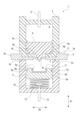
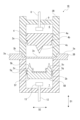
- FIG. 1 is a schematic cross-sectional view showing a configuration example of a fuse unit according to an embodiment of the present invention
- 2 is a schematic perspective view showing an enlarged view of a cut tip portion of the fuse unit and a bus bar.
- FIG. 4 is a schematic diagram showing a state in which the bus bar is separated into a first portion and a second portion;
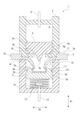
- FIG. 4 is a schematic cross-sectional view showing an example of a fuse unit in a cut state.
- FIG. 13 is a schematic cross-sectional view showing another example of a fuse unit in a cut state, in which both tip ends of a first portion and a second portion are in contact with an insulating portion.
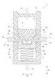
- FIG. 11 is a schematic cross-sectional view showing an example of a reconnected state of the fuse unit.
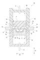
- FIG. FIG. 11 is a schematic cross-sectional view showing an example of a fuse unit according to a first modified example.
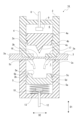
- FIG. 11 is a schematic cross-sectional view showing an example of a normal state of the fuse unit according to the second modified example.
- FIG. 11 is a schematic cross-sectional view showing an example of a reconnected state of the fuse unit according to the second modified example.
- FIG. 13 is a schematic cross-sectional view showing a portion of an example of a fuse unit according to a third modified example.
- FIG. 1 shows an example of the configuration of a fuse unit 1 according to the present invention.
- the fuse unit 1 is used to protect components arranged downstream and reduce the impact on personnel by cutting off electrical connections upstream closer to the power source.
- the fuse unit 1 may be provided near an on-board battery or near an ECU (Electronic Control Unit) or the like to be protected.
- ECU Electronic Control Unit
- the fuse unit 1 includes a case body 2 in which a space is formed, a bus bar 3 formed of a conductor, a cutting portion 4 for cutting the bus bar 3, and a reconnecting portion 5 for restoring the electrical connection after the bus bar 3 has been cut.
- the case body 2 is made of an insulator, and the bus bar 3 is disposed approximately in the center of the internal space of the case body 2. Inside the case body 2, there is a first space 6 formed on one side of the bus bar 3, and a second space 7 formed on the opposite side of the first space 6 with respect to the bus bar 3.
- the direction in which the first space 6 and the second space 7 are aligned will be referred to as a vertical direction D1
- a plane perpendicular to the vertical direction D1 will be referred to as a horizontal plane.
- the horizontal plane in the description does not have to be perpendicular to the direction of gravity when the fuse unit 1 is actually attached.
- the direction in which the bus bar 3 extends inside the fuse unit 1 is referred to as a left-right direction D2, and the direction perpendicular to the up-down direction D1 and the left-right direction D2 is referred to as a front-rear direction D3.
- the left-right direction D2 and the front-rear direction D3 in the description are merely for convenience of description, and the mounting direction of the fuse unit 1 is not limited to these directions.
- the first space 6 and the second space 7 may be cylindrical spaces, cubic spaces, or other spaces.
- first space 6 and the second space 7 are each cylindrical spaces.
- the cutting portion 4 is disposed in the first space 6.
- the cutting portion 4 has a large diameter portion 4a that is approximately the same size as the cross section of the first space 6, a small diameter portion 4b that is a portion that continues downward from the large diameter portion 4a, and a cutting tip portion 4c that protrudes downward from the center of the small diameter portion 4b.
- the cutting tip 4c has a triangular prism shape with its axial direction in the front-to-rear direction D3, and its width in the left-to-right direction D2 decreases as it goes downward.
- the case body 2 has a support protrusion 2a formed on the inner circumferential surface of the first space 6, approximately near the center in the up-down direction D1.
- the support protrusions 2a may be provided in a number spaced apart fashion in the circumferential direction on the inner surface of the first space 6, or may be provided in the shape of a ring without interruption in the circumferential direction.
- the cutting portion 4 is maintained in a position midway in the first space 6 in the up-down direction D1 because the step at the boundary between the large diameter portion 4a and the small diameter portion 4b is supported from below by the support protrusion 2a.
- the first space 6 When the cutting part 4 is in place, the first space 6 is separated into an upper space and a lower space, and a mechanism for pushing the cutting part 4 downward in an emergency is disposed in the upper space.
- a mechanism for pushing the cutting part 4 downward in an emergency is disposed in the upper space.
- an ignition wire 8 and explosives 9 disposed at its tip are disposed in the space above the cutting part 4.
- the reconnection portion 5 is disposed in the second space 7.
- the reconnection portion 5 is formed as a conductor, and includes a cylindrical base portion 5a having approximately the same size as a cross section of the second space 7, a first connection portion 5b protruding upward from one end of the base portion 5a in the left-right direction D2, and a second connection portion 5c protruding upward from the other end of the base portion 5a in the left-right direction D2.
- the vertical cross section of the reconnection portion 5 is substantially U-shaped.
- the second space 7 is separated into an upper space and a lower space, and a spring member 10 is placed in the lower space to urge the reconnection part 5 upward.
- the spring member 10 is, for example, a compression coil spring.
- the reconnection portion 5 is provided as a flange portion 5d that protrudes outward at the boundary portion between the base portion 5a and the first connection portion 5b and the second connection portion 5c.
- the case body 2 has an inwardly protruding movement restricting portion 2b formed on the inner circumferential surface of the second space 7 approximately in the vicinity of the center in the up-down direction D1.
- the reconnection part 5, which is disposed in the second space 7, is restricted from further upward movement by the engagement of the flange part 5d with the movement restriction part 2b.
- the inner surface of the first connection part 5b of the reconnection part 5, the inner surface of the second connection part 5c, and the upper surface of the base part 5a between the first connection part 5b and the second connection part 5c are formed as a recess 5e.
- An insulating part 11 made of an insulator is attached to the surface of the recess 5e.
- a mechanism for pushing the reconnection part 5 upward is disposed.
- an ignition wire 12 and explosives 13 disposed at its tip are disposed in the lower space of the reconnection part 5.
- the busbar 3 has a thick portion 3a, a part of which is located outside the case body 2, a thin portion 3b located in the center of the case body 2 in the left-right direction D2 and directly below the cutting tip 4c of the cutting portion 4, and a connection portion 3c that connects the thick portion 3a and the thin portion 3b.
- the thin-walled portion 3b is provided as a cuttable portion that divides the busbar 3 into a first portion 14 and a second portion 15 when the cutting portion 4 falls and hits it (see FIG. 3).
- the case body 2 is formed with a first restricting portion 16 that protrudes inward and restricts the upward movement of the first portion 14 of the bus bar 3 in the first space 6 . Further, the case body 2 is formed with a second restricting portion 17 that protrudes inward and restricts the upward movement of the second portion 15 of the bus bar 3 in the first space 6 .
- the first restricting portion 16 and the second restricting portion 17 may be integrally formed as a circumferentially continuous flange that protrudes inward in the first space 6.
- the fuse unit 1 is capable of adopting a disconnected state in an emergency in which a part of the bus bar 3 is cut off and the electrical connection is severed, and a reconnected state in which the electrical connection that was severed in the bus bar 3 is restored.
- the tip of the first portion 14 and the tip of the second portion 15 may hang down and come into contact with the reconnection portion 5.
- the first part 14 and the second part 15 are kept electrically disconnected because the insulating part 11 is attached to the surface of the recess 5e of the reconnection part 5.
- the first regulating portion 16 is provided on the case body 2, thereby regulating the upward movement of the first portion 14, and the contact area between the first connection portion 5b and the first portion 14 is increased.
- the second restricting portion 17 is provided on the case body 2, the upward movement of the second portion 15 is restricted, and the contact area between the second connection portion 5c and the second portion 15 is increased.
- the length of the reconnection portion 5 in the vertical direction D1 may be set so that the lower surface of the reconnection portion 5 is supported by the movement restricting portion 2b when the first connection portion 5b and the second connection portion 5c are pressed against the first portion 14 and the second portion 15, respectively. This makes it easy to maintain the first connecting portion 5b and the second connecting portion 5c in a state where they are firmly pressed against the first portion 14 and the second portion 15, respectively.
- the reconnection portion 5 is positioned below the busbar 3 at a distance so that even if the tips of the broken first and second portions 14 and 15 hang down as shown in FIG. 5 (shown by the two-dot chain line in FIG. 7), they will not reach them.
- a fuse unit 1B in this modification differs from the above-described example in the shape of a case body 2B, the shape of a bus bar 3B, and the shape of a reconnection portion 5B.
- the busbar 3B has a thick portion 3a, a thin portion 3b, and a connection portion 3c, but the portion disposed in the first space 6 and the second space 7 is substantially the thin portion 3b.
- the reconnection portion 5B which is disposed in the second space 7 below the busbar 3B, has a cylindrical base 5f, a first connection portion 5b that protrudes upward from near one end of the base 5f in the left-right direction D2 and has a conical tip, and a second connection portion 5c that protrudes upward from near the other end of the base 5f in the left-right direction D2 and has a conical tip.
- An upper portion of the base portion 5f is formed as a protruding engagement portion 5g that protrudes at least in the left-right direction D2.
- the protruding engagement portion 5g is positioned above the movement restriction portion 2b of the case body 2B, thereby restricting downward movement of the reconnection portion 5B (for example, movement due to gravity). Unlike the other examples described above, no upward force is applied to the reconnection portion 5B by the spring member 10 or the like.
- a second movement restriction portion 2c that restricts the upward movement of the reconnection portion 5B is formed slightly above the portion of the inner circumferential surface of the second space 7 of the case body 2B where the protruding engagement portion 5g abuts.
- the reconnection portion 5B is held in a state in which the protruding engagement portion 5g is sandwiched between the movement restriction portion 2b and the second movement restriction portion 2c, thereby restricting movement in the up-down direction D1.
- case body 2B does not include a first restricting portion 16 that restricts the upward movement of the first portion 14 of the bus bar 3B, and a second restricting portion 17 that restricts the upward movement of the second portion 15.
- the reconnected state of fuse unit 1B in this modified example is shown in FIG.
- the first connection portion 5b in the reconnection portion 5B penetrates the first portion 14 of the broken bus bar 3B, and the second connection portion 5c penetrates the second portion 15.
- the tips of the first part 14 and the second part 15 are cone-shaped, making it easier for the first connection part 5b and the second connection part 5c to penetrate the first part 14 and the second part 15.
- first connection portion 5b and the second connection portion 5c may be provided with a barb to make it easier to maintain the first portion 14 and the second portion 15 in a penetrated state.
- a regulating portion may be provided to regulate the upward movement of the first portion 14 and the second portion 15. It is desirable that the restricting portion is provided so as not to interfere with the tip end of the first connecting portion 5b and the tip end of the second connecting portion 5c in the penetrated state.
- an escape hole may be formed in the cutting portion 4 to allow the tip portion of the first connection portion 5b, which has penetrated the first part 14, to escape.
- a retreat hole may be provided in the cutting portion 4 to allow the tip portion of the second connection portion 5 c to escape when it has penetrated the second portion 15 .
- a restricting portion may be provided on the inner peripheral surface of the first space 6 of the case body 2B.
- the first and second restricting parts 16 and 17 in the case body 2B, the spring member 10, and the like are not provided, thereby reducing the weight of the fuse unit 1B.
- FIG. 1C of this modification A third example of the modified example is shown in FIG.
- the shape of a cutting portion 4C is different from that of the above-described example.
- the cutting portion 4C does not have a large diameter portion 4a and a small diameter portion 4b, but has a cylindrical portion 4d, a protruding portion 4e that protrudes outward from approximately the center of the cylindrical portion 4d in the up-down direction D1, and a cutting tip portion 4c.
- the spring member 10 is used as a compression spring below the reconnection portion 5, but a spring member as a tension spring may be provided above the reconnection portion 5.
- the movement restriction portion 2b of the case body 2 only needs to be provided in a position and shape that restricts the upward movement of the reconnection portion 5.
- the fuse unit 1 (1A, 1B, 1C) of the present invention comprises a bus bar 3 (3B) made of a conductor and having a cut portion (thin portion 3b), a case body 2 (2B) supporting two points on either side of the cut portion, a cutting portion 4 (4C) made of an insulator and disposed in a first space 6 formed in the internal space of the case body 2 (2B) on one side of the bus bar 3 (3B), and a reconnection portion 5 (5B) made of a conductor and disposed in a second space 7 formed in the internal space of the case body 2 (2B) on the opposite side of the first space 6 in the bus bar 3 (3B).
- the cutting portion 4 (4C) has a cutting tip 4c that cuts the bus bar 3 (3B) at the cut portion into a first portion 14 and a second portion 15 and is movable into the second space 7.
- the reconnection portion 5 ( 5 B) has a first connection portion 5 b that contacts the first portion 14 and a second connection portion 5 c that contacts the second portion 15 .
- the fuse unit 1 (1A, 1B, 1C) of the present invention for example, by applying the fuse unit 1 (1A, 1B, 1C) of the present invention to a vehicle, after the bus bar 3 (3B) is cut to avoid secondary damage due to leakage current in the event of an accident, the electrical connection of the bus bar 3 (3B) can be restored, allowing the vehicle to be moved to ensure safety at the accident site.
- the electrical connection of bus bar 3 (3B) can be restored, allowing the vehicle to be moved to ensure safety at the accident site.
- by restoring the electrical connection of bus bar 3 (3B) it becomes possible to use power from the vehicle battery to condition the interior of the vehicle, thereby improving the survival chances of the occupants.
- the reconnection portion 5 (5B) in the fuse unit 1 (1B, 1C) of the present invention is U-shaped with the first connection portion 5b and the second connection portion 5c formed in a protruding shape toward the bus bar 3 (3B), and an insulating portion 11 may be provided in the U-shaped recess 5e of the reconnection portion 5 (5B).
- an insulating portion 11 may be provided in the U-shaped recess 5e of the reconnection portion 5 (5B).
- the insulating portion 11 is provided in the recess 5e and is not provided at the tip portions of the first connection portion 5b and the second connection portion 5c, it is possible to prevent the restoration of the electrical connection between the first portion 14 and the second portion 15 from being hindered.
- the case body 2 in the fuse unit 1 (1A, 1C) of the present invention may be provided with a first regulating portion 16 that regulates movement of the first part 14 toward the first space 6, and a second regulating portion 17 that regulates movement of the second part 15 toward the first space 6.
- a first regulating portion 16 that regulates movement of the first part 14 toward the first space 6
- a second regulating portion 17 that regulates movement of the second part 15 toward the first space 6.
- the fuse unit 1 (1A, 1C) of the present invention is provided with a spring member 10 that biases the reconnection portion 5 in a direction approaching the bus bar 3, and the case body 2 may be provided with a movement restricting portion 2b that restricts movement of the reconnection portion 5 in the direction approaching the bus bar 3.
- the movement restriction portion 2b simply by releasing the restriction by the movement restriction portion 2b, the first connection portion 5b and the second connection portion 5c in the reconnection portion 5 are pressed against the first portion 14 and the second portion 15, respectively, thereby restoring the electrical connection between the first portion 14 and the second portion 15.
- the movement restricting portion 2b may be configured to be variable between a state in which it protrudes from the inner wall of the case body 2 and a state in which it is stored. In that case, it is not necessary to dispose the explosive 13 below the reconnection portion 5, which can contribute to improving safety.
- the spring member 10 in the fuse unit 1 (1A, 1C) of the present invention may urge the reconnection portion 5 in a direction approaching the bus bar 3 (3B) with the first connection portion 5b in contact with the first portion 14 and the second connection portion 5c in contact with the second portion 15.
- the state in which the first connection portion 5b is pressed against the first portion 14 and the second connection portion 5c is pressed against the second portion 15 continues. Therefore, the electrical connection between the first portion 14 and the second portion 15 can be continuously ensured after reconnection.
Landscapes
- Fuses (AREA)
Priority Applications (4)
| Application Number | Priority Date | Filing Date | Title |
|---|---|---|---|
| PCT/JP2023/033320 WO2025057323A1 (ja) | 2023-09-13 | 2023-09-13 | ヒューズユニット |
| JP2025545358A JPWO2025057323A1 (https=) | 2023-09-13 | 2023-09-13 | |
| CN202380067822.9A CN119998912A (zh) | 2023-09-13 | 2023-09-13 | 熔断器单元 |
| US19/173,605 US20250239426A1 (en) | 2023-09-13 | 2025-04-08 | Fuse unit |
Applications Claiming Priority (1)
| Application Number | Priority Date | Filing Date | Title |
|---|---|---|---|
| PCT/JP2023/033320 WO2025057323A1 (ja) | 2023-09-13 | 2023-09-13 | ヒューズユニット |
Related Child Applications (1)
| Application Number | Title | Priority Date | Filing Date |
|---|---|---|---|
| US19/173,605 Continuation US20250239426A1 (en) | 2023-09-13 | 2025-04-08 | Fuse unit |
Publications (1)
| Publication Number | Publication Date |
|---|---|
| WO2025057323A1 true WO2025057323A1 (ja) | 2025-03-20 |
Family
ID=95021053
Family Applications (1)
| Application Number | Title | Priority Date | Filing Date |
|---|---|---|---|
| PCT/JP2023/033320 Pending WO2025057323A1 (ja) | 2023-09-13 | 2023-09-13 | ヒューズユニット |
Country Status (4)
| Country | Link |
|---|---|
| US (1) | US20250239426A1 (https=) |
| JP (1) | JPWO2025057323A1 (https=) |
| CN (1) | CN119998912A (https=) |
| WO (1) | WO2025057323A1 (https=) |
Citations (4)
| Publication number | Priority date | Publication date | Assignee | Title |
|---|---|---|---|---|
| JPH11232977A (ja) * | 1998-02-17 | 1999-08-27 | Harness Syst Tech Res Ltd | 回路遮断装置 |
| JP2000156142A (ja) * | 1998-09-18 | 2000-06-06 | Harness Syst Tech Res Ltd | 回路遮断器 |
| JP2000251599A (ja) * | 1999-03-03 | 2000-09-14 | Yazaki Corp | 電源遮断器 |
| CN108807027A (zh) * | 2018-08-07 | 2018-11-13 | 西安中熔电气股份有限公司 | 一种外部驱动的快速电流切断装置 |
-
2023
- 2023-09-13 WO PCT/JP2023/033320 patent/WO2025057323A1/ja active Pending
- 2023-09-13 JP JP2025545358A patent/JPWO2025057323A1/ja active Pending
- 2023-09-13 CN CN202380067822.9A patent/CN119998912A/zh active Pending
-
2025
- 2025-04-08 US US19/173,605 patent/US20250239426A1/en active Pending
Patent Citations (4)
| Publication number | Priority date | Publication date | Assignee | Title |
|---|---|---|---|---|
| JPH11232977A (ja) * | 1998-02-17 | 1999-08-27 | Harness Syst Tech Res Ltd | 回路遮断装置 |
| JP2000156142A (ja) * | 1998-09-18 | 2000-06-06 | Harness Syst Tech Res Ltd | 回路遮断器 |
| JP2000251599A (ja) * | 1999-03-03 | 2000-09-14 | Yazaki Corp | 電源遮断器 |
| CN108807027A (zh) * | 2018-08-07 | 2018-11-13 | 西安中熔电气股份有限公司 | 一种外部驱动的快速电流切断装置 |
Also Published As
| Publication number | Publication date |
|---|---|
| US20250239426A1 (en) | 2025-07-24 |
| CN119998912A (zh) | 2025-05-13 |
| JPWO2025057323A1 (https=) | 2025-03-20 |
Similar Documents
| Publication | Publication Date | Title |
|---|---|---|
| EP1654793B1 (en) | Circuit interruption device | |
| JP2002512422A (ja) | 特に高電流強さ用電気回路の分離装置 | |
| EP4276875B1 (en) | Electric circuit breaker device | |
| JPH11353997A (ja) | 電流遮断装置 | |
| US20240186083A1 (en) | Electric circuit breaker device | |
| EP4503082A1 (en) | Electric circuit breaker | |
| ES2927364T3 (es) | Contacto eléctrico normalmente abierto | |
| US12548722B2 (en) | Electric circuit breaker device | |
| JP2000156142A (ja) | 回路遮断器 | |
| WO2025057323A1 (ja) | ヒューズユニット | |
| EP4270434B1 (en) | Electric circuit breaking device | |
| WO2022210354A1 (ja) | 電気回路遮断装置 | |
| JP7703814B2 (ja) | 能動/受動ヒューズモジュール | |
| WO2023152907A1 (ja) | 電気回路切替装置 | |
| JP2000149747A (ja) | 回路遮断器 | |
| JP2000090794A (ja) | 回路遮断器 | |
| US20250149278A1 (en) | Electric circuit breaker device | |
| US20250157768A1 (en) | Electric circuit breaker device | |
| US20240177952A1 (en) | Electric circuit breaker device | |
| US20240420904A1 (en) | Electric circuit breaker device | |
| EP4481788A1 (en) | Electric circuit breaking device | |
| JP2000082372A (ja) | 回路遮断器 | |
| KR100352843B1 (ko) | 충돌시전기차단장치 | |
| WO2024161861A1 (ja) | 遮断装置 | |
| JP2000082371A (ja) | 回路遮断器 |
Legal Events
| Date | Code | Title | Description |
|---|---|---|---|
| WWE | Wipo information: entry into national phase |
Ref document number: 202380067822.9 Country of ref document: CN |
|
| ENP | Entry into the national phase |
Ref document number: 2025545358 Country of ref document: JP Kind code of ref document: A |
|
| WWE | Wipo information: entry into national phase |
Ref document number: 2025545358 Country of ref document: JP |
|
| 121 | Ep: the epo has been informed by wipo that ep was designated in this application |
Ref document number: 23952217 Country of ref document: EP Kind code of ref document: A1 |
|
| WWP | Wipo information: published in national office |
Ref document number: 202380067822.9 Country of ref document: CN |