WO2025052706A1 - 積層セラミック電子部品 - Google Patents
積層セラミック電子部品 Download PDFInfo
- Publication number
- WO2025052706A1 WO2025052706A1 PCT/JP2024/013808 JP2024013808W WO2025052706A1 WO 2025052706 A1 WO2025052706 A1 WO 2025052706A1 JP 2024013808 W JP2024013808 W JP 2024013808W WO 2025052706 A1 WO2025052706 A1 WO 2025052706A1
- Authority
- WO
- WIPO (PCT)
- Prior art keywords
- electrode
- layer
- multilayer ceramic
- laminate
- internal
- Prior art date
- Legal status (The legal status is an assumption and is not a legal conclusion. Google has not performed a legal analysis and makes no representation as to the accuracy of the status listed.)
- Pending
Links
Images








Classifications
-
- H—ELECTRICITY
- H01—ELECTRIC ELEMENTS
- H01G—CAPACITORS; CAPACITORS, RECTIFIERS, DETECTORS, SWITCHING DEVICES, LIGHT-SENSITIVE OR TEMPERATURE-SENSITIVE DEVICES OF THE ELECTROLYTIC TYPE
- H01G4/00—Fixed capacitors; Processes of their manufacture
- H01G4/002—Details
- H01G4/228—Terminals
- H01G4/232—Terminals electrically connecting two or more layers of a stacked or rolled capacitor
-
- H—ELECTRICITY
- H01—ELECTRIC ELEMENTS
- H01G—CAPACITORS; CAPACITORS, RECTIFIERS, DETECTORS, SWITCHING DEVICES, LIGHT-SENSITIVE OR TEMPERATURE-SENSITIVE DEVICES OF THE ELECTROLYTIC TYPE
- H01G4/00—Fixed capacitors; Processes of their manufacture
- H01G4/002—Details
- H01G4/005—Electrodes
- H01G4/012—Form of non-self-supporting electrodes
-
- H—ELECTRICITY
- H01—ELECTRIC ELEMENTS
- H01G—CAPACITORS; CAPACITORS, RECTIFIERS, DETECTORS, SWITCHING DEVICES, LIGHT-SENSITIVE OR TEMPERATURE-SENSITIVE DEVICES OF THE ELECTROLYTIC TYPE
- H01G4/00—Fixed capacitors; Processes of their manufacture
- H01G4/002—Details
- H01G4/018—Dielectrics
- H01G4/06—Solid dielectrics
- H01G4/08—Inorganic dielectrics
- H01G4/12—Ceramic dielectrics
-
- H—ELECTRICITY
- H01—ELECTRIC ELEMENTS
- H01G—CAPACITORS; CAPACITORS, RECTIFIERS, DETECTORS, SWITCHING DEVICES, LIGHT-SENSITIVE OR TEMPERATURE-SENSITIVE DEVICES OF THE ELECTROLYTIC TYPE
- H01G4/00—Fixed capacitors; Processes of their manufacture
- H01G4/30—Stacked capacitors
-
- H—ELECTRICITY
- H01—ELECTRIC ELEMENTS
- H01G—CAPACITORS; CAPACITORS, RECTIFIERS, DETECTORS, SWITCHING DEVICES, LIGHT-SENSITIVE OR TEMPERATURE-SENSITIVE DEVICES OF THE ELECTROLYTIC TYPE
- H01G4/00—Fixed capacitors; Processes of their manufacture
- H01G4/35—Feed-through capacitors or anti-noise capacitors
Definitions
- the present invention relates to multilayer ceramic electronic components.
- a through-type three-terminal capacitor is known as a decoupling capacitor used to stabilize a power supply voltage supplied to an integrated circuit component (IC) that operates at high speed, or as a noise suppression component for a power supply line supplied to an integrated circuit component (IC).
- a through-type three-terminal capacitor generally includes a laminate having a first main surface and a second main surface that face each other, a first side surface and a second side surface that face each other, and a first end surface and a second end surface that face each other. Inside the laminate, a plurality of first internal electrode layers and second internal electrode layers are alternately arranged in the lamination direction.
- the first internal electrode layer has both ends led out to the first end surface and the second end surface
- the second internal electrode layer has both ends led out to the first side surface and the second side surface.
- the first internal electrode layer is connected to the first external electrode and the second external electrode
- the second internal electrode layer is connected to the third external electrode and the fourth external electrode.
- Patent Document 1 a structure such as that in Patent Document 1 has been proposed as a structure for a low-capacity through-type three-terminal capacitor that can suppress an increase in capacitance while also suppressing an increase in DC resistance.
- a structure such as that in Patent Document 1 has been proposed as a structure for a low-capacity through-type three-terminal capacitor that can suppress an increase in capacitance while also suppressing an increase in DC resistance.
- the main object of this invention is to provide a multilayer ceramic electronic component that can handle a larger current.
- the multilayer ceramic electronic component according to the present invention comprises a laminate having a first main surface and a second main surface that face each other in the stacking direction, a first surface and a second surface that face each other in a first direction perpendicular to the stacking direction, and a third surface and a fourth surface that face each other in a second direction perpendicular to the stacking direction and the first direction, and at least four external electrodes arranged on any one of the first surface, the second surface, the third surface, and the fourth surface, and a joining electrode that electrically joins at least two of the external electrodes at the same potential is arranged on either the first main surface or the second main surface, and when the DC resistance of the multilayer ceramic capacitor is Rdc1 and the DC resistance of the joining electrode is Rdc3, Rdc1 ⁇ Rdc3 is satisfied.
- a joining electrode is disposed on either the first or second principal surface, electrically joining at least two of the external electrodes having the same potential.
- the DC resistance of the multilayer ceramic capacitor is Rdc1 and the DC resistance of the joining electrode is Rdc3, Rdc1 ⁇ Rdc3 is satisfied. Therefore, the combined resistance of the multilayer ceramic capacitor and the joining electrode is smaller than the resistance of the multilayer ceramic capacitor alone. This makes it possible to provide a multilayer ceramic electronic component that can handle a larger current.
- This invention provides a multilayer ceramic electronic component that can handle larger currents.
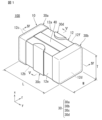
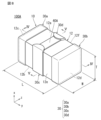
- FIG. 1 is an external perspective view showing a multilayer ceramic electronic component according to a first embodiment of the present invention
- 1 is a front view of a multilayer ceramic electronic component according to a first embodiment of the present invention
- 1 is a plan view of a multilayer ceramic electronic component according to a first embodiment of the present invention.
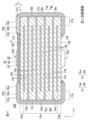
- 4 is a cross-sectional view taken along line IV-IV in FIG. 1.
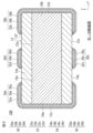
- 2 is a cross-sectional view taken along line VV in FIG. 1.
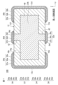
- 6 is a cross-sectional view taken along line VI-VI in FIG. 4.
- 7 is a cross-sectional view taken along line VII-VII in FIG. 4.
- FIG. 11 is an external perspective view of a multilayer ceramic electronic component according to a modified example of the first embodiment of the present invention.
- FIG. 1 is a cross-sectional view in a lamination direction showing a mounting structure of a multilayer ceramic electronic component according to a first embodiment of the present invention.
- 3 is a cross-sectional view in a second direction showing the mounting structure of the multilayer ceramic electronic component according to the first embodiment of the present invention.
- FIG. FIG. 5 is a cross-sectional view showing a first modified example of the multilayer ceramic capacitor according to the first embodiment of the present invention, and corresponds to the cross-sectional view of FIG. 4 .
- FIG. 7 is a cross-sectional view showing a first modified example of the multilayer ceramic capacitor according to the first embodiment of the present invention, and corresponds to the cross-sectional view of FIG. 5 .
- FIG. 13 is a cross-sectional view taken along line XIII-XIII in FIG. 11.
- 14 is a cross-sectional view taken along line XIV-XIV in FIG. 11.
- FIG. 5 is a cross-sectional view showing a second modified example of the multilayer ceramic capacitor according to the first embodiment of the present invention, and corresponds to the cross-sectional view of FIG. 4 .
- FIG. 7 is a cross-sectional view showing a second modified example of the multilayer ceramic capacitor according to the first embodiment of the present invention, which corresponds to the cross-sectional view of FIG. 5 .
- FIG. 11 is an external perspective view showing a multilayer ceramic electronic component according to a second embodiment of the present invention.
- FIG. 5 is a front view of a multilayer ceramic electronic component according to a second embodiment of the present invention.
- FIG. 5 is a side view of a multilayer ceramic electronic component according to a second embodiment of the present invention.
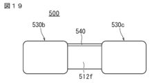
- FIG. 5 is a plan view of a multilayer ceramic electronic component according to a second embodiment of the present invention.
- 18 is a cross-sectional view taken along line XXI-XXI in FIG. 17.
- 18 is a cross-sectional view taken along line XXII-XXII in FIG. 17.
- 18 is a cross-sectional view taken along line XXI-XXI in FIG. 17.
- 18 is a cross-sectional view taken along line XXIV-XXIV in FIG. 17.
- 18 is a cross-sectional view taken along line XXV-XXV in FIG. 17.
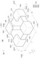
- FIG. 18 is an exploded perspective view of the laminate shown in FIG. 17.
- Multilayer Ceramic Electronic Component A multilayer ceramic electronic component 100 according to an embodiment of the present invention will be described.
- FIG. 1 is an external perspective view showing a multilayer ceramic electronic component according to a first embodiment of the present invention.
- FIG. 2 is a front view of the multilayer ceramic electronic component according to the first embodiment of the present invention.
- FIG. 3 is a plan view of the multilayer ceramic electronic component according to the first embodiment of the present invention.
- FIG. 4 is a cross-sectional view taken along line IV-IV in FIG. 1.
- FIG. 5 is a cross-sectional view taken along line V-V in FIG. 1.
- FIG. 6 is a cross-sectional view taken along line VI-VI in FIG. 4.
- FIG. 7 is a cross-sectional view taken along line VII-VII in FIG. 4.
- a multilayer ceramic electronic component 100 includes a multilayer ceramic capacitor 10 and a bonding electrode 40.
- the multilayer ceramic capacitor 10 includes a laminate 12 and a plurality of external electrodes 30 .
- the laminate 12 has a first main surface 12a and a second main surface 12b that face the stacking direction x, a first surface 12c and a second surface 12d that face the first direction y that is perpendicular to the stacking direction x, and a third surface 12e and a fourth surface 12f that face the second direction z that is perpendicular to the stacking direction x and the first direction y.
- the direction that connects the first main surface 12a and the second main surface 12b of the laminate 12 is the stacking direction x.
- the laminate 12 has a rectangular parallelepiped shape. It is preferable that the corners and ridges of the laminate 12 are rounded. The corners are the portions where three adjacent faces of the laminate 12 intersect, and the ridges are the portions where two adjacent faces of the laminate 12 intersect. In addition, unevenness may be formed on some or all of the first main surface 12a and the second main surface 12b, the first surface 12c and the second surface 12d, and the third surface 12e and the fourth surface 12f.
- the laminate 12 has a plurality of dielectric layers 14 and a plurality of internal electrodes 16.
- the dielectric layers 14 have an inner dielectric layer 14a and an outer dielectric layer 14b.
- the internal electrodes 16 have a first internal electrode 16a and a second internal electrode 16b.
- the laminate 12 also has an inner layer 18, a first outer layer 20a located on the first main surface 12a side, and a second outer layer 20b located on the second main surface 12b side.
- the first outer layer 20a is located on the first main surface 12a side of the laminate 12, and is an assembly of multiple outer dielectric layers 14b located between the first main surface 12a and the internal electrode 16 closest to the first main surface 12a.
- the second outer layer 20b is located on the second main surface 12b side of the laminate 12, and is an assembly of multiple outer dielectric layers 14b located between the second main surface 12b and the internal electrode 16 closest to the second main surface 12b.
- the area sandwiched between the first outer layer 20a and the second outer layer 20b is the inner layer 18.
- the inner layer portion 18 has a first internal electrode 16a, one end of which is exposed on the first surface 12c and the other end of which is exposed on the second surface 12d, a second internal electrode 16b, one end of which is exposed on the third surface 12e and the other end of which is exposed on the fourth surface 12f, and an inner dielectric layer 14a.
- the dielectric layer 14 may be formed of, for example, a dielectric material.
- a dielectric ceramic composed of a main component such as BaTiO 3 , CaTiO 3 , SrTiO 3 , or CaZrO 3 may be used.
- a subcomponent such as a Mn compound, an Fe compound, a Cr compound, a Co compound, or a Ni compound may be added to these main components.
- the inner dielectric layer 14a and the outer dielectric layer 14b may be composed of the same dielectric material, or may be composed of different dielectric materials for the purpose of dividing the functions of the inner layer portion 18 and the outer layer portions 20a and 20b.
- at least one of Si, Mg, Ba, and Mn may be added as an additive. The additive is present between the ceramic particles.
- the inner dielectric layer 14a contains a large amount of CaTiO3 or CaZrO3 as a dielectric component, it is possible to make it difficult for insulation breakdown to occur between the first inner electrode 16a and the second inner electrode 16b.
- the inner dielectric layer 14a may have SrTiO3 or the like as a main component. Separately from this, in order to increase the capacitance of the multilayer ceramic capacitor 10, it is preferable to form the layer from a material with a high dielectric constant, for example, BaTiO3 .
- the dielectric layer 14 may have a plurality of crystal grains including a perovskite type compound having a basic structure of BaTiO 3 .
- the number of dielectric layers 14 to be stacked is not particularly limited, but is preferably 5 to 1000, including the first outer layer 20a and the second outer layer 20b.
- the thickness of the dielectric layer 14 is preferably, for example, 0.3 ⁇ m to 6.0 ⁇ m.
- the internal electrodes 16 include first internal electrodes 16a and second internal electrodes 16b.
- the first internal electrodes 16a and the second internal electrodes 16b are alternately laminated with the inner dielectric layer 14a interposed therebetween.
- the first internal electrode 16a is disposed on the surface of the inner dielectric layer 14a.
- the first internal electrode 16a faces the first principal surface 12a and the second principal surface 12b, and has a first opposing electrode portion 22a facing the second internal electrode 16b, a first extraction electrode portion 24a connected to the first opposing electrode portion 22a and drawn out to the first surface 12c, and a second extraction electrode portion 24b drawn out to the second surface 12d.
- the shape of the first opposing electrode portion 22a of the first internal electrode 16a is not particularly limited, but is preferably rectangular in plan view. However, the corners in plan view may be rounded or may be formed at an angle in plan view (tapered). It may also be tapered in plan view, with an incline in either direction.
- the shapes of the first and second extraction electrode portions 24a and 24b of the first internal electrode 16a are not particularly limited, but are preferably rectangular in plan view. However, the corners in plan view may be rounded or may be formed at an angle in plan view (tapered). They may also be tapered in plan view, with an incline toward either side.
- the second internal electrode 16b is disposed on a surface of an inner dielectric layer 14a different from the inner dielectric layer 14a on which the first internal electrode 16a is disposed.
- the second internal electrode 16b has a second opposing electrode portion 22b that faces the first internal electrode 16a, a third extraction electrode portion 24c that is connected to the second opposing electrode portion 22b and is extended to the third surface 12e, and a fourth extraction electrode portion 24d that is extended to the fourth surface 12f.
- the shape of the second opposing electrode portion 22b of the second internal electrode 16b is not particularly limited, but is preferably rectangular in plan view. However, the corners in plan view may be rounded or may be formed at an angle in plan view (tapered). It may also be tapered in plan view, with an incline in either direction.
- the shapes of the third extraction electrode portion 24c and the fourth extraction electrode portion 24d of the second internal electrode 16b are not particularly limited, but are preferably rectangular in plan view. However, the corners in plan view may be rounded or may be formed at an angle in plan view (tapered). Also, they may be tapered in plan view with an incline toward either side.
- the laminate 12 has a side portion (W gap) 26a of the laminate 12 located between one end in the second direction z of the first opposing electrode portion 22a of the first internal electrode 16a and the second opposing electrode portion 22b of the second internal electrode 16b and the third surface 12e, and a side portion (W gap) 26b of the laminate 12 located between one end in the second direction z of the first opposing electrode portion 22a of the first internal electrode 16a and the second opposing electrode portion 22b of the second internal electrode 16b and the fourth surface 12f.
- the laminate 12 also has an end (L gap) 27a of the laminate 12 located between one end in the first direction y of the first opposing electrode portion 22a of the first internal electrode 16a and the second opposing electrode portion 22b of the second internal electrode 16b and the first surface 12c, and an end (L gap) 27b of the laminate 12 located between one end in the first direction y of the first opposing electrode portion 22a of the first internal electrode 16a and the second opposing electrode portion 22b of the second internal electrode 16b and the second surface 12d.
- the first internal electrode 16a and the second internal electrode 16b can be made of an appropriate conductive material, such as metals such as Ni, Cu, Ag, Pd, and Au, or alloys containing at least one of these metals, such as Ni-Cu alloys and Ag-Pd alloys, but are not limited to these. Furthermore, the first internal electrode 16a and the second internal electrode 16b may be made of the same conductive material or different conductive materials.
- the potential barrier height at the interface between the internal electrode 16 and the dielectric layer 14 is increased, and the electric field concentration at the interface between the internal electrode 16 and the dielectric layer 14 can be alleviated, leading to improved high temperature load reliability.
- Sn is included in only one of the internal electrodes 16, either the first internal electrode 16a or the second internal electrode 16b, it can be sufficiently effective.
- the total number of the first internal electrodes 16a and the second internal electrodes 16b is 2 or more and 1000 or less.
- the thickness of the first internal electrodes 16a and the second internal electrodes 16b is not particularly limited, but is preferably, for example, 0.3 ⁇ m or more and 6.0 ⁇ m or less.
- the external electrodes 30 include a plurality of external electrodes 30 connected to the first internal electrode 16a and the second internal electrode 16b.
- the external electrodes 30 include a first external electrode 30a, a second external electrode 30b, a third external electrode 30c, and a fourth external electrode 30d.
- the first external electrode 30a is disposed on the first surface 12c and is connected to the first internal electrode 16a.
- the first external electrode 30a may also be disposed on a portion of the first main surface 12a, a portion of the second main surface 12b, a portion of the third surface 12e, and a portion of the fourth surface 12f.
- the second external electrode 30b is disposed on the second surface 12d and is connected to the first internal electrode 16a.
- the second external electrode 30b may also be disposed on a portion of the first main surface 12a, a portion of the second main surface 12b, a portion of the third surface 12e, and a portion of the fourth surface 12f.
- the third external electrode 30c is disposed on the third surface 12e and is connected to the second internal electrode 16b.
- the third external electrode 30c may also be disposed on a portion of the first main surface 12a and a portion of the second main surface 12b.
- the fourth external electrode 30d is disposed on the fourth surface 12f and is connected to the second internal electrode 16b.
- the fourth external electrode 30d may also be disposed on a portion of the first main surface 12a and a portion of the second main surface 12b.
- the first external electrode 30a to the fourth external electrode 30d are arranged on the first principal surface 12a or the second principal surface 12b, but they do not have to be formed on either principal surface. In that case, the dimension of the multilayer ceramic capacitor 10 in the stacking direction x can be reduced, and the multilayer ceramic capacitor 10 can be made thinner.
- the first opposing electrode portion 22a of the first internal electrode 16a and the second opposing electrode portion 22b of the second internal electrode 16b face each other via the inner dielectric layer 14a, forming a capacitance. Therefore, a capacitance can be obtained between the first external electrode 30a and the second external electrode 30b to which the first internal electrode 16a is connected, and the third external electrode 30c and the fourth external electrode 30d to which the second internal electrode 16b is connected, and the characteristics of a capacitor are expressed.
- the first external electrode 30a, the second external electrode 30b, the third external electrode 30c, and the fourth external electrode 30d each preferably have a base electrode layer 32 and a plating layer.
- the plating layer preferably has a lower plating layer 34 and an upper plating layer 36.
- the first external electrode 30a preferably has a first base electrode layer 32a, a first lower plating layer 34a, and a first upper plating layer 36a.
- the second external electrode 30b preferably has a second base electrode layer 32b, a second lower plating layer 34b, and a second upper plating layer 36b.
- the third external electrode 30c preferably has a third base electrode layer 32c, a third lower plating layer 34c, and a third upper plating layer 36c.
- the fourth external electrode 30d preferably has a fourth base electrode layer 32d, a fourth lower plating layer 34d, and a fourth upper plating layer 36d.
- the base electrode layer 32 includes at least one selected from a baked layer, a conductive resin layer, a thin film layer, etc.
- the baked layer contains a metal component and a glass component.
- the glass component contains at least one selected from B, Si, Ba, Mg, Al, Li, etc.
- the metal component of the baked layer contains at least one selected from Cu, Ni, Ag, Pd, Ag-Pd alloy, Au, etc.
- the baked layer may be a multi-layer structure.
- the base electrode layer 32 when the base electrode layer 32 is formed by a baked layer, it may be configured to contain the same type of component as the dielectric layer 14 and a metal. In this case, if the dielectric layer 14 is made of a CaZrO system, the same type of component is Ca or Zr.
- the baked layer is formed by applying a conductive paste containing a glass component and a metal component to the laminate 12 and baking it.
- the baked layer may be formed by simultaneously baking a laminated chip having an internal electrode 16 and a dielectric layer 14 and a conductive paste applied to the laminated chip, or by baking a laminated chip having an internal electrode 16 and a dielectric layer 14 to obtain a laminate 12, and then applying and baking a conductive paste.
- a laminated chip having an internal electrode 16 and a dielectric layer 14 and a conductive paste applied to the laminated chip are simultaneously baked, it is preferable to add a dielectric component instead of the glass component, or to add both to form the baked layer.
- the thickness in the first direction y connecting the first surface 12c and the second surface 12d of the first baked layer and the second baked layer at the center of the stacking direction x connecting the first main surface 12a and the second main surface 12b of the first baked layer and the second baked layer located on the first surface 12c and the second surface 12d is preferably, for example, 5 ⁇ m or more and 55 ⁇ m or less.
- the thickness in the stacking direction x connecting the first principal surface 12a and the second principal surface 12b of the first baked layer and the second baked layer at the center of the first direction y connecting the first surface 12c and the second surface 12d of the first baked layer and the second baked layer located on the first principal surface 12a or the second principal surface 12b is preferably, for example, 1 ⁇ m or more and 30 ⁇ m or less.
- the conductive resin layer may be disposed on the baked layer so as to cover the baked layer, or may be disposed directly on the laminate 12 without providing a baked layer.
- the conductive resin layer may completely cover the baked layer, or may cover only a portion of the baked layer.
- the conductive resin layer may be multiple layers.
- the conductive resin layer contains a thermosetting resin and a metal. Because the conductive resin layer contains a thermosetting resin, it is more flexible than a baked layer made of, for example, a plating film or a baked conductive paste. Therefore, even if the multilayer ceramic capacitor 10 is subjected to a physical shock or a shock caused by a thermal cycle, the conductive resin layer functions as a buffer layer and can prevent cracks in the multilayer ceramic capacitor 10.
- the metal contained in the conductive resin layer can be Ag, Cu, Ni, Sn, Bi or an alloy containing these. It is also possible to use a metal powder with an Ag-coated surface. When using a metal powder with an Ag-coated surface, it is preferable to use Cu, Ni, Sn, Bi or an alloy powder of these.
- the reason for using Ag conductive metal powder as the conductive metal is that Ag has the lowest resistivity of all metals, making it suitable as an electrode material, and because Ag is a precious metal, it does not oxidize and has high weather resistance. In addition, it is possible to make the base metal cheaper while maintaining the above-mentioned properties of Ag.
- the metal contained in the conductive resin layer may be Cu or Ni that has been subjected to an anti-oxidation treatment.
- the metal contained in the conductive resin layer may be a metal powder whose surface is coated with Sn, Ni, or Cu.
- Ag, Cu, Ni, Sn, Bi, or an alloy powder of these metals it is preferable to use Ag, Cu, Ni, Sn, Bi, or an alloy powder of these metals.
- the metal contained in the conductive resin layer is mainly responsible for the electrical conductivity of the conductive resin layer. Specifically, when the conductive fillers come into contact with each other, an electrical path is formed inside the conductive resin layer.
- the metal contained in the conductive resin layer can be spherical or flat, but it is preferable to use a mixture of spherical metal powder and flat metal powder.
- thermosetting resins such as epoxy resin, phenolic resin, urethane resin, silicone resin, polyimide resin, etc.
- epoxy resin which has excellent heat resistance, moisture resistance, adhesion, etc., is one of the most suitable resins.
- the conductive resin layer preferably contains a curing agent in addition to the thermosetting resin.
- a curing agent in addition to the thermosetting resin.
- various known compounds such as phenol-based, amine-based, acid anhydride-based, imidazole-based, active ester-based, and amide-imide-based compounds can be used as the curing agent for the epoxy resin.
- the thickest part of the conductive resin layer is preferably, for example, 5 ⁇ m or more and 50 ⁇ m or less.
- the thin film layer may be formed on the surface of the laminate 12.
- the thin film layer is formed by a thin film formation method such as a sputtering method or a vapor deposition method.
- the thin film layer is a layer of 1 ⁇ m or less in which metal particles are deposited.
- the base electrode layer 32 may be formed of a plating layer.
- the plating preferably contains at least one metal selected from Cu, Ni, Sn, Pd, Au, Ag, Bi, Zn, etc., or an alloy containing the metal.
- the plating layer preferably does not contain glass, and the metal ratio per unit area of the plating layer is preferably 99% by volume or more.
- the lower layer plating layer 34 includes a first lower layer plating layer 34a arranged to cover the first lower electrode layer 32a, a second lower layer plating layer 34b arranged to cover the second lower electrode layer 32b, a third lower layer plating layer 34c arranged to cover the third lower electrode layer 32c, and a fourth lower layer plating layer 34d arranged to cover the fourth lower electrode layer 32d.
- the lower plating layer 34 contains, for example, at least one selected from Cu, Ni, Sn, Ag, Pd, Ag-Pd alloy, Au, etc.
- the lower plating layer 34 is preferably Ni-plated. If the lower plating layer 34 is Ni-plated, the base electrode layer 32 can be prevented from being eroded by solder when mounting the multilayer ceramic capacitor 10.
- the thickness of the lower plating layer 34 is, for example, 1 ⁇ m or more and 8 ⁇ m or less.
- the upper layer plating layer 36 includes a first upper layer plating layer 36a arranged to cover the first lower layer plating layer 34a, a second upper layer plating layer 36b arranged to cover the second lower layer plating layer 34b, a third upper layer plating layer 36c arranged to cover the third lower layer plating layer 34c, and a fourth upper layer plating layer 36d arranged to cover the fourth lower layer plating layer 34d.
- the upper plating layer 36 contains, for example, at least one selected from Cu, Ni, Sn, Ag, Pd, Ag-Pd alloy, Au, etc.
- the upper plating layer 36 is preferably Sn-plated. If the upper plating layer 36 is Sn-plated, the wettability of the solder when mounting the multilayer ceramic capacitor 10 is improved, making mounting easier.
- the thickness of the upper plating layer 36 is, for example, 1 ⁇ m or more and 8 ⁇ m or less.
- the plating layer has a two-layer structure consisting of a lower plating layer 34 and an upper plating layer 36, but this is not limited to this and may have a three-layer structure. If the plating layer has a three-layer structure, it is preferable that the layers from the laminate 12 side are Sn plating, Ni plating, and Sn plating.
- the dimension in the first direction y of the multilayer ceramic capacitor 10 including the laminate 12 and the external electrode 30 is defined as the L dimension.
- the L dimension is preferably 0.51 mm or more and 3.2 mm or less.
- the dimension in the second direction z of the multilayer ceramic capacitor 10 including the laminate 12 and the external electrode 30 is defined as the W dimension.
- the W dimension is preferably 0.21 mm or more and 2.5 mm or less.
- the dimension in the stacking direction x of the multilayer ceramic capacitor 10 including the laminate 12 and the external electrode 30 is defined as the T dimension.
- the T dimension is preferably 0.05 mm or more and 2.5 mm or less.
- a joining electrode 40 that electrically joins at least two or more of the external electrodes 30 that have the same potential is arranged on either the first main surface 12a or the second main surface 12b of the laminate 12.
- the joining electrode 40 electrically joins the first external electrode 30a and the second external electrode 30b of the multilayer ceramic capacitor 10 on the first main surface 12a of the laminate 12.
- the bonding electrode 40 includes a bonding base electrode 42, a bonding underlayer plating layer 44 that covers the bonding base electrode 42, and a bonding upper layer plating layer 46 that covers the bonding underlayer plating layer 44.
- the bonding electrode 40 may be composed of only the bonding base electrode 42.
- the bonding base electrode 42 is formed, for example, by a sputtering electrode.
- the DC resistance of the multilayer ceramic capacitor 10 is Rdc1 and the DC resistance of the joining electrode 40 is Rdc3, it is preferable that Rdc1 ⁇ Rdc3. If Rdc1>Rdc3, the current including the noise component is less likely to flow through the capacitor due to the voltage division effect, and the noise removal effect is reduced.
- Rdc3 is preferably 1.0 to 5.0 times Rdc1. Basically, lowering the combined resistance makes it easier for current to flow. However, if Rdc3 is more than 5.0 times Rdc1, the effect of making it easier for current to flow is reduced.
- the thickness t 1 of the joining electrode 40 in the lamination direction x is preferably smaller than the thickness t 2 of the external electrode 30 disposed on the same plane as the joining electrode 40 in the lamination direction x.
- the joining electrode 40 is thicker than the dimension in the stacking direction x of the external electrode 30 arranged on the main surface, the dimension in the stacking direction x of the entire multilayer ceramic capacitor 10 will be large. Therefore, by making the thickness in the stacking direction x of the joining electrode 40 thinner than the thickness in the stacking direction x of the external electrode 30 arranged on the same plane as the joining electrode 40, it is possible to increase Rdc3 and allow a large current to flow through the multilayer ceramic capacitor 10 without the dimension in the stacking direction x of the multilayer ceramic capacitor 10 becoming too large.
- the method for measuring the Rdc of each of the joining electrodes 40 and the multilayer ceramic capacitor 10 is as follows. That is, first, the external electrode 30 of the multilayer ceramic capacitor 10 connected to the bonding electrode 40 is removed from the surface of the laminate 12, for example, by laser, polishing, or solvent treatment. At this time, it is sufficient to remove either one of the external electrodes 30 connected to the bonding electrode 40 from the surface of the laminate 12. Thereafter, each of the bonding electrode 40 and the multilayer ceramic capacitor 10 is measured using a four-terminal method.
- the main component of the joining electrode 40 is preferably a metal such as Cu, NiCr, or NiCu, but is not limited to this.
- the porosity of the bonding base electrode 42 of the bonding electrode 40 is preferably greater than the porosity of the base electrode layer 32 of the external electrode 30. By making the porosity of the bonding base electrode 42 greater than the porosity of the base electrode layer 32, Rdc3 can be increased.
- the porosity is defined as the area when the gaps and other areas are binarized when viewed in the lamination direction x of the bonding base electrode 42 and the base electrode layer 32 when the bonding underlayer plating layer 44 and the bonding upper layer plating layer 46 are peeled off.
- the flexural strength of the multilayer ceramic capacitor 10 can be improved by placing the joining electrode 40 on either the first main surface 12a or the second main surface 12b of the laminate 12.
- the joining electrode 40 shown in FIG. 1 is rectangular, but is not limited to this, and the width of the central region in the first direction y may be smaller or larger than the width of the end portions.
- the joining electrode 40 may have a tapered shape in which the dimension in the second direction z becomes smaller from one end side to the other end side, or from the other end to the one end side, or may be formed in a tapered stepped shape.
- a joining electrode 40 that electrically joins the first external electrode 30a and the second external electrode 30b is disposed on the first main surface 12a. If the DC resistance of the multilayer ceramic capacitor is Rdc1 and the DC resistance of the joining electrode 40 is Rdc3, then Rdc1 ⁇ Rdc3. Therefore, the combined resistance of the multilayer ceramic capacitor 10 and the joining electrode 40 is smaller than the resistance of the multilayer ceramic capacitor 10 alone, and therefore a multilayer ceramic capacitor 10 that can handle a larger current can be provided.
- FIG. 8 is an external perspective view of a multilayer ceramic electronic component according to a modification of the first embodiment of the present invention.
- the same reference numerals are used for the same or corresponding configurations as those in Figs. 1 to 7, and detailed description thereof will be omitted.
- the multilayer ceramic electronic component 100A of the modified example includes a multilayer ceramic capacitor 10 and a bonding electrode 40A, as shown in FIG. 8.
- the joining electrode 40A electrically joins the third external electrode 30c and the fourth external electrode 30d of the multilayer ceramic capacitor 10 on the first main surface 12a of the laminate 12.
- FIG. 9 is a cross-sectional view in the stacking direction showing the mounting structure of a multilayer ceramic electronic component according to a first embodiment of the present invention.
- FIG. 10 is a cross-sectional view in a second direction showing the mounting structure of a multilayer ceramic electronic component according to a first embodiment of the present invention.
- the mounting structure 300 of the multilayer ceramic electronic component according to this embodiment includes the multilayer ceramic electronic component 100 according to this embodiment and a mounting substrate 60.
- the mounting substrate 60 includes a substrate core material 62 and a connecting conductor (conductor land) 64.
- the core material 62 of the substrate is, for example, a substrate made of a material in which a base material made of a mixture of glass fabric (cloth) and nonwoven glass fabric is impregnated with epoxy resin or polyimide resin, or a ceramic substrate manufactured by baking a sheet of a mixture of ceramics and glass.
- the core material 62 of the substrate may be a single-layer substrate, or may be configured as a substrate made of multiple laminated layers.
- the thickness of the core material 62 of the substrate is not particularly limited, but is preferably, for example, 200 ⁇ m or more and 800 ⁇ m or less.
- One of the main surfaces of the substrate core material 62 constitutes the substrate side mounting surface 62a on which the conductor lands 64 are arranged and which serves as the mounting surface for the multilayer ceramic electronic component 100.
- the conductor land 64 includes a first conductor land 64a, a second conductor land 64b, a third conductor land 64c, and a fourth conductor land 64d.
- the first conductor land 64a is a portion electrically connected and mechanically joined to the first external electrode 30a of the multilayer ceramic capacitor 10 by the bonding material 66.
- the second conductor land 64b is a portion electrically connected and mechanically joined to the second external electrode 30b of the multilayer ceramic capacitor 10 by the bonding material 66.
- the third conductor land 64c is a portion electrically connected and mechanically joined to the third external electrode 30c of the multilayer ceramic capacitor 10 by the bonding material 66.
- the fourth conductor land 64d is a portion electrically connected and mechanically joined to the fourth external electrode 30d of the multilayer ceramic capacitor 10 by the bonding material 66.
- the conductor land 64 may be provided on the main surface of the board core material 62 opposite the board-side mounting surface 62a.
- the material of the conductor land 64 is not particularly limited, but metals such as Cu, Au, Pd, and Pt can be used.
- the thickness of the conductor land 64 i.e., the dimension in the stacking direction x, is not particularly limited, but is preferably 20 ⁇ m or more and 200 ⁇ m or less, for example.
- the bonding material 66 can be, for example, a high heat resistant epoxy adhesive or solder.
- the mounting board 60 corresponds to the mounting board of the present invention.
- the core material 62 of the board corresponds to the core material of the board of the present invention.
- the board-side mounting surface 62a corresponds to the mounting surface of the present invention.
- the multiple conductor lands 64 correspond to the multiple connecting conductors of the present invention.
- the connecting conductors of the present invention are not limited to so-called lands, and are not limited to other uses, functions, shapes, names, etc., as long as they are conductors that are provided between the multilayer ceramic capacitor 10 and the mounting board 60 and can electrically connect the two.
- the first external electrode 30a and the second external electrode 30b are connected to the anode. This shortens the current distance, ensuring moisture resistance reliability while preventing an increase in insulation resistance.
- the multilayer ceramic electronic component 100 is preferably mounted so that the bonding electrodes 40 of the multilayer ceramic electronic component 100 are arranged in the opposite direction to the mounting substrate 60.
- the bonding electrodes 40 of the multilayer ceramic electronic component 100 are arranged on the first main surface side (non-mounting surface side) of the multilayer ceramic capacitor 10, and the multilayer ceramic capacitor 10 of the multilayer ceramic electronic component 100 is mounted on the mounting substrate 60 side.
- a conductive paste for a dielectric sheet and an internal electrode is prepared.
- the conductive paste for the dielectric sheet and the internal electrode contains a binder and a solvent. Known binders and solvents can be used.
- a conductive paste for the internal electrodes is printed in a predetermined pattern on the dielectric sheet by, for example, inkjet printing, screen printing, or gravure printing. This prepares a dielectric sheet on which the pattern of the first internal electrode is formed and a dielectric sheet on which the pattern of the second internal electrode is formed. After that, the sheet on which the first internal electrode is printed and the sheet on which the second internal electrode is printed are laminated together to form the portion that will become the inner layer 18.
- a predetermined number of dielectric sheets that do not have an internal electrode pattern printed on them are stacked to form the first outer layer 20a on the first main surface 12a.
- the portion that will become the inner layer 18 prepared above is stacked, and a predetermined number of dielectric sheets that do not have an internal electrode pattern printed on them are stacked on top of the portion that will become the inner layer 18 to form the second outer layer 20b on the second main surface 12b. This completes the production of the laminated sheet.
- the laminated sheet is pressed in the stacking direction using a means such as a hydrostatic press to create a laminated block.
- the laminated block is cut to a predetermined size to cut out laminated chips.
- the corners and edges of the laminated chips may be rounded by barrel polishing or the like.
- the firing temperature depends on the ceramic and internal electrode materials, but is preferably 900°C or higher and 1400°C or lower.
- a bonding electrode 40 is formed on the surface of the first main surface 12a of the laminate 12.
- the bonding electrode 40 is formed by using a method of applying a conductive paste by extruding it through a slit or a screen printing method, and a bonding base electrode 42 is formed.
- a first base electrode layer 32a of the first external electrode 30a and a second base electrode layer 32b of the second external electrode 30b are formed on the first surface 12c and the second surface 12d of the laminate 12 on which the joining electrode 40 is formed.
- a third base electrode layer 32c of the third external electrode 30c and a fourth base electrode layer 32d of the fourth external electrode 30d are formed on the third surface 12e and the fourth surface 12f of the laminate 12 obtained by firing.
- a conductive paste containing a glass component and a metal component is applied, and then a baking process is performed to form the base electrode layer 32.
- the third base electrode layer 32c of the third external electrode 30c and the fourth base electrode layer 32d of the fourth external electrode 30d are formed on the third surface 12e and the fourth surface 12f of the laminate 12 obtained by firing.
- various methods can be used to form the third base electrode layer 32c and the fourth base electrode layer 32d.
- a method can be used in which a conductive paste is extruded through a slit and applied.
- the third base electrode layer 32c and the fourth base electrode layer 32d can be formed not only on the third surface 12e and the fourth surface 12f, but also on a part of the first main surface 12a and a part of the second main surface 12b.
- roller transfer method when the third base electrode layer 32c and the fourth base electrode layer 32d are formed not only on the third surface 12e and the fourth surface 12f but also on a part of the first main surface 12a and a part of the second main surface 12b, it is possible to form the third base electrode layer 32c and the fourth base electrode layer 32d on a part of the first main surface 12a and a part of the second main surface 12b by increasing the pressing pressure during the roller transfer.
- the first base electrode layer 32a of the first external electrode 30a and the second base electrode layer 32b of the second external electrode 30b are formed on the first surface 12c and the second surface 12d of the laminate 12 obtained by firing.
- various methods can be used to form the first base electrode layer 32a and the second base electrode layer 32b.
- a method such as dipping, they can be formed so as to extend not only to the first surface 12c and the second surface 12d, but also to a part of the first main surface 12a and a part of the second main surface 12b, a part of the third surface 12e, and a part of the fourth surface 12f.
- first and second base electrode layers 32a and 32b, and the third and fourth base electrode layers 32c and 32d may be fired simultaneously.
- the conductive resin layer can be formed by the following method.
- the conductive resin layer may be formed on the surface of the baked layer, or the conductive resin layer may be formed directly on the laminate without forming a baked layer.
- the conductive resin layer is formed by applying a conductive resin paste containing a thermosetting resin and a metal onto a baking layer or a laminate, and then performing a heat treatment at a temperature of 250°C to 550°C to thermally cure the resin and form a conductive resin layer.
- the atmosphere during the heat treatment is preferably a N2 atmosphere.
- the conductive resin paste can be applied using a method similar to the method for forming the base electrode layer 32 as a baked layer, such as a method of applying the conductive paste by extruding it through a slit or a roller transfer method.
- a lower layer plating layer 34 is formed on the base electrode layer 32 and on the surface of the laminate 12, and an upper layer plating layer 36 is formed to cover the lower layer plating layer 34.
- a bonding lower layer plating layer 44 is formed on the surface of the bonding base electrode 42, and a bonding upper layer plating layer 46 is formed to cover the bonding lower layer plating layer 44.
- a Ni plating layer is formed on the base electrode layer 32 as the lower layer plating layer 34.
- a Sn plating layer is formed on the surface of the lower layer plating layer 34 as the upper layer plating layer 36.
- a Ni plating layer is formed on the bonding base electrode 42 as the bonding lower layer plating layer 44, and a Sn plating layer is formed on the surface of the bonding lower layer plating layer 44 as the bonding upper layer plating layer 46.
- electrolytic plating has the disadvantage that a pretreatment using a catalyst or the like is required to improve the plating deposition speed, which complicates the process. Therefore, it is usually preferable to use electrolytic plating.
- the multilayer ceramic electronic component 100 shown in Figure 1 can be manufactured.
- a fired laminate 12 may be manufactured, and an external electrode 30 may be formed on the laminate 12, after which a joining electrode 40 may be formed.
- a bonding electrode 40 is formed on the surface of the first main surface 12a of the laminate 12 of the multilayer ceramic capacitor 10 by screen printing or sputtering.
- a multilayer ceramic capacitor 10A according to a first modification of the present embodiment differs from the multilayer ceramic capacitor 10 according to the present embodiment only in the structure of the laminate 12A of the multilayer ceramic capacitor 10A. Therefore, the same parts as those in the multilayer ceramic capacitor 10 are given the same reference numerals and descriptions thereof are omitted.
- FIG. 11 is a cross-sectional view showing a first modified example of the multilayer ceramic capacitor according to the first embodiment of the present invention, and corresponds to the cross-sectional view of FIG. 4.
- FIG. 12 is a cross-sectional view showing a first modified example of the multilayer ceramic capacitor according to the first embodiment of the present invention, and corresponds to the cross-sectional view of FIG. 5.
- FIG. 13 is a cross-sectional view taken along line XIII-XIII in FIG. 11.
- FIG. 14 is a cross-sectional view taken along line XIV-XIV in FIG. 11.
- the multilayer ceramic capacitor 10A has a laminate 12A and an external electrode 30.
- the laminate 12A includes a first main surface 12a and a second main surface 12b that face the stacking direction x, a first surface 12c and a second surface 12d that face the first direction y that is perpendicular to the stacking direction x, and a third surface 12e and a fourth surface 12f that face the second direction z that is perpendicular to the stacking direction x and the first direction y.
- the laminate 12A has a plurality of dielectric layers 14 and a plurality of internal electrodes 16.
- the dielectric layers 14 include an inner dielectric layer 14a and an outer dielectric layer 14b.
- the internal electrodes 16 have a first internal electrode 16a and a second internal electrode 16b.
- a first dummy electrode 25a is arranged at the ends (L gap) 27a, 27b of the laminate 12A so as to be exposed on the first surface 12c, and a second dummy electrode 25b is arranged so as to be exposed on the second surface 12d.
- the first dummy electrode 25a and the second dummy electrode 25b are preferably arranged on the same plane as the second internal electrode 16b and have the same thickness as the second internal electrode 16b.
- the current path can be shortened by reducing the coverage of the first dummy electrode 25a and the second dummy electrode 25b.
- the first dummy electrode 25a and the second dummy electrode 25b may be disposed on the first outer layer portion 20a and the second outer layer portion 20b. In this case, it is preferable to dispose them on the portions corresponding to the positions obtained by moving the ends (L gaps) 27a and 27b of the laminate 12 in parallel in the lamination direction x. By disposing them in this manner, it becomes easier to form the plating layer when the plating layer is provided without providing the base electrode layer 32.
- the first dummy electrode 25a and the second dummy electrode 25b are provided on the same plane as the second internal electrode 16b
- the first dummy electrode 25a and the second dummy electrode 25b can be arranged on the same plane as the second internal electrode 16b by printing the first dummy electrode 25a and the second dummy electrode 25b together with the second internal electrode 16b when printing the second internal electrode 16b.
- a third dummy electrode 25c may be arranged on the sides (W gap) 26a, 26b of the laminate 12A so as to be exposed on the third surface 12e, and a fourth dummy electrode 25d may be arranged so as to be exposed on the fourth surface 12f.
- the third dummy electrode 25c and the fourth dummy electrode 25d are preferably arranged on the same plane as the first internal electrode 16a and have the same thickness as the first internal electrode 16a.
- the current path can be shortened by reducing the coverage of the third dummy electrode 25c and the fourth dummy electrode 25d.
- the third dummy electrode 25c and the fourth dummy electrode 25d may be disposed on the first outer layer 20a and the second outer layer 20b. In this case, it is preferable to dispose them on the portions corresponding to the positions obtained by moving the side portions (W gaps) 26a and 26b of the laminate 12A in parallel in the lamination direction x. By disposing them in this manner, it becomes easier to form the plating layer when the plating layer is provided without providing the base electrode layer 32.
- the third dummy electrode 25c and the fourth dummy electrode 25d are provided on the same plane as the first internal electrode 16a, the third dummy electrode 25c and the fourth dummy electrode 25d can be printed together with the second internal electrode 16b when printing the first internal electrode 16a, thereby placing the third dummy electrode 25c and the fourth dummy electrode 25d on the same plane as the first internal electrode 16a.
- the multilayer ceramic capacitor 10A shown in Figures 11 to 14 has a first dummy electrode 25a, a second dummy electrode 25b, a third dummy electrode 25c, and a fourth dummy electrode 25d arranged on the sides (W gaps) 26a, 26b of the laminate 12A and the ends (L gaps) 27a, 27b of the laminate 12A, preventing distortion during pressing.
- the first dummy electrode 25a, the second dummy electrode 25b, the third dummy electrode 25c, and the fourth dummy electrode 25d are arranged on the sides (W gaps) 26a, 26b of the laminate 12A and the ends (L gaps) 27a, 27b of the laminate 12A, but the present invention is not limited to this.
- the first dummy electrode 25a and the second dummy electrode 25b may be arranged at the ends (L gaps) 27a, 27b of the laminate 12A
- the third dummy electrode 25c and the fourth dummy electrode 25d may not be arranged at the sides (W gaps) 26a, 26b of the laminate 12A.
- the third dummy electrode 25c and the fourth dummy electrode 25d may be arranged on the sides (W gaps) 26a, 26b of the laminate 12A, and the first dummy electrode 25a and the second dummy electrode 25b may not be arranged on the ends (L gaps) 27a, 27b of the laminate 12A.
- a multilayer ceramic capacitor 10B according to a second modification of the present embodiment differs from the multilayer ceramic capacitor 10 according to the present embodiment only in the structure of the laminate 12B of the multilayer ceramic capacitor 10B. Therefore, the same parts as those in the multilayer ceramic capacitor 10 are given the same reference numerals and descriptions thereof are omitted.
- FIG. 15 is a cross-sectional view showing a second modified example of the multilayer ceramic capacitor according to the first embodiment of the present invention, and corresponds to the cross-sectional view of FIG. 4.
- FIG. 16 is a cross-sectional view showing a second modified example of the multilayer ceramic capacitor according to the first embodiment of the present invention, and corresponds to the cross-sectional view of FIG. 5.
- the laminate 12B includes a first main surface 12a and a second main surface 12b that face the stacking direction x, a first surface 12c and a second surface 12d that face the first direction y that is perpendicular to the stacking direction x, and a third surface 12e and a fourth surface 12f that face the second direction z that is perpendicular to the stacking direction x and the first direction y.
- the laminate 12B has a plurality of dielectric layers 14 and a plurality of internal electrodes 16.
- the dielectric layers 14 include an inner dielectric layer 14a and an outer dielectric layer 14b.
- the internal electrodes 16 have a first internal electrode 16a and a second internal electrode 16b.
- the laminate 12B has an inner layer 18 and a first outer layer 20a and a second outer layer 20b arranged to sandwich the inner layer 18 in the stacking direction x.
- the inner dielectric layer 14a of the inner layer portion 18 may be arranged so as to be sandwiched between the first inner electrodes 16a and 16a. In this case, the first inner electrodes 16a and 16a are arranged continuously via the inner dielectric layer 14a of the inner layer portion 18.
- the inner dielectric layer 14a of the inner layer portion 18 may be disposed so as to be sandwiched between the second inner electrodes 16b. In this case, the second inner electrodes 16b are disposed continuously via the dielectric layer 14 of the inner layer portion 18.
- the inner dielectric layer 14a of the inner layer portion 18 is composed of dielectric ceramic particles having a perovskite structure, for example, with a perovskite-type compound containing Ba and Ti as the main component. At least one of Si, Mg, Ba, and Mn may be added as an additive to these main components. The additive is present between the ceramic particles.
- the inner layer portion 18 of the laminate 12B has a capacitance forming portion 28 where the first internal electrode 16a and the second internal electrode 16b face each other via the dielectric layer 14 to form a capacitance, and an internal electrode laminate portion 29 which is a region where two or more first internal electrodes 16a are laminated in succession.
- the capacitance forming portion 28 is what allows the laminated ceramic capacitor 10B to exhibit its capacitor characteristics.
- the internal electrode laminate 29 is arranged so as to be divided into a plurality of internal electrode laminates 29 by the second internal electrode 16b. This disperses the aggregate of the first internal electrodes 16a, improving the heat dissipation effect and achieving the effect of suppressing temperature rise.
- the internal electrode laminate 29 is divided by two second internal electrodes 16b, and the internal electrode laminate 29 is divided into a first internal electrode laminate 29a, a second internal electrode laminate 29b, and a third internal electrode laminate 29c.
- the second internal electrode 16b which is arranged so as to divide the internal electrode laminated portion 29, which is a region in which two or more first internal electrodes 16a are laminated in succession, may be arranged singly. This makes it possible to laminate more first internal electrodes 16a, thereby achieving the effect of reducing DC resistance.
- the second internal electrodes 16b which are arranged so as to divide the internal electrode laminated portion 29, which is a region in which two or more first internal electrodes 16a are laminated in succession, may be arranged by laminating two or more of them in succession. This makes it possible to ensure more sufficient connectivity between the second internal electrodes 16b and the external electrode 30, even if the number of second internal electrodes 16b is reduced.
- the second internal electrode 16b may be disposed in the internal electrode laminate 29, which is a region where two or more first internal electrodes 16a located on the first main surface 12a side of the laminate 12B are laminated in succession, i.e., between the first internal electrode laminate 29a and the first main surface 12a, and in the internal electrode laminate 29, which is a region where two or more first internal electrodes 16a located on the second main surface 12b side of the laminate 12B are laminated in succession, i.e., between the third internal electrode laminate 29c and the second main surface 12b.
- the second internal electrode 16b does not have to be disposed in the internal electrode laminate 29, which is a region in which two or more first internal electrodes 16a located on the first main surface 12a side of the laminate 12B are laminated in succession, i.e., between the first internal electrode laminate 29a and the first main surface 12a, and in the internal electrode laminate 29, which is a region in which two or more first internal electrodes 16a located on the second main surface 12b side of the laminate 12B are laminated in succession, i.e., between the third internal electrode laminate 29c and the second main surface 12b.
- This increases the distance from the surface of the laminate 12B to the capacitance forming portion 28 where capacitance is formed, and the effect of preventing insulation resistance degradation from occurring even if a crack occurs from the surface of the laminate 12B due to an external load can be obtained.
- the thickness of the inner dielectric layer 14a adjacent to the second inner electrode 16b is preferably greater than the thickness of the inner dielectric layer 14a sandwiched between the first inner electrodes 16a. This makes it possible to stack more first inner electrodes 16a, thereby further increasing the effect of reducing DC resistance.
- the thickness of the second internal electrode 16b is greater than the thickness of the first internal electrode 16a. This ensures connectivity between the third lead electrode portion 24c of the second internal electrode 16b and the third external electrode 30c arranged on the first surface 12c, and ensures connectivity between the fourth lead electrode portion 24d of the second internal electrode 16b and the fourth external electrode 30d arranged on the second surface 12d, even when the capacitance is reduced.
- FIG. 17 is an external perspective view showing a multilayer ceramic electronic component according to a second embodiment of the present invention.
- FIG. 18 is a front view of the multilayer ceramic electronic component according to the second embodiment of the present invention.
- FIG. 19 is a side view of the multilayer ceramic electronic component according to the second embodiment of the present invention.
- FIG. 20 is a plan view of the multilayer ceramic electronic component according to the second embodiment of the present invention.
- FIG. 21 is a cross-sectional view taken along line XXI-XXI in FIG. 17.
- FIG. 22 is a cross-sectional view taken along line XXII-XXII in FIG. 17.
- FIG. 23 is a cross-sectional view taken along line XXI-XXI in FIG. 17.
- FIG. 21 is a cross-sectional view taken along line XXI-XXI in FIG. 17.
- FIG. 22 is a cross-sectional view taken along line XXII-XXII in FIG. 17.
- FIG. 24 is a cross-sectional view taken along line XXIV-XXIV in FIG. 17.
- FIG. 25 is a cross-sectional view taken along line XXV-XXV in FIG. 17.
- FIG. 26 is an exploded perspective view of the laminate shown in FIG. 17.
- the multilayer ceramic electronic component 500 includes a multilayer ceramic capacitor 510 and a bonding electrode 540.
- the multilayer ceramic capacitor 510 comprises a laminate 512 and a plurality of external electrodes 530.
- the laminate 512 has a first main surface 512a and a second main surface 512b that face the stacking direction x, a first surface 512c and a second surface 512d that face a first direction y that is perpendicular to the stacking direction x, and a third surface 512e and a fourth surface 512f that face a second direction z that is perpendicular to the stacking direction x and the first direction y.
- the direction that connects the first main surface 512a and the second main surface 512b of the laminate 512 is the stacking direction x.
- the corners and ridges of the laminate 512 are rounded.
- the corners refer to the portions where three adjacent faces of the laminate 512 intersect, and the ridges refer to the portions where two adjacent faces of the laminate 512 intersect.
- unevenness may be formed on some or all of the first and second main faces 512a and 512b, the first and second faces 512c and 512d, and the third and fourth faces 512e and 512f.
- the laminate 512 includes a plurality of dielectric layers 514 and a plurality of internal electrodes 516.
- the dielectric layers 514 include an inner dielectric layer 514a and an outer dielectric layer 514b.
- the internal electrodes 516 include a first internal electrode 516a and a second internal electrode 516b.
- the laminate 512 also has an inner layer 518, a first outer layer 520a located on the first main surface 512a side, and a second outer layer 520b located on the second main surface 512b side.
- the first outer layer 520a is located on the first main surface 512a side of the laminate 512, and is an assembly of multiple outer dielectric layers 514b located between the first main surface 512a and the internal electrode 516 closest to the first main surface 512a.
- the second outer layer portion 520b is located on the second main surface 512b side of the laminate 512, and is an assembly of multiple outer dielectric layers 514b located between the second main surface 512b and the internal electrode 516 closest to the second main surface 512b.
- the area sandwiched between the first outer layer 520a and the second outer layer 520b is the inner layer 518.
- the inner layer portion 518 has a first internal electrode 516a having one end exposed to the first surface 512c and the third surface 512e and the other end exposed to the second surface 512d and the fourth surface 512f, a second internal electrode 516b having one end exposed to the first surface 512c and the third surface 512e and the other end exposed to the second surface 512d and the third surface 512e, and an inner dielectric layer 514a.
- the dielectric layer 514 may be formed of, for example, a dielectric material.
- a dielectric ceramic mainly composed of BaTiO3 , CaTiO3 , SrTiO3 , or CaZrO3 may be used as the dielectric material.
- a material containing a subcomponent such as a Mn compound, an Fe compound, a Cr compound, a Co compound, or a Ni compound added to the main component may be used.
- the inner dielectric layer 514a and the outer dielectric layer 514b may be made of the same dielectric material or different dielectric materials.
- the inner dielectric layer 514a contains a large amount of CaTiO3 or CaZrO3 as a dielectric component, it is possible to make it difficult for insulation breakdown to occur between the first inner electrode 516a and the second inner electrode 516b.
- the inner dielectric layer 514a may be mainly composed of SrTiO3 or the like.
- the inner dielectric layer 514a is formed of a material with a high dielectric constant, for example, BaTiO3 .
- the dielectric layer 514 may have a plurality of crystal grains including a perovskite-type compound having a BaTiO 3 basic structure.
- the number of dielectric layers 514 to be stacked is not particularly limited, but is preferably 5 to 1000, including the first outer layer 520a and the second outer layer 520b.
- the thickness of the dielectric layer 514 is preferably, for example, 0.3 ⁇ m to 6.0 ⁇ m.
- the internal electrodes 516 include a plurality of first internal electrodes 516a and a plurality of second internal electrodes 516b.
- the first internal electrodes 516a and the second internal electrodes 516b are alternately stacked with the dielectric layers 514 interposed therebetween.
- the first internal electrode 516a is disposed on the surface of the inner dielectric layer 514a.
- the first internal electrode 516a faces the first main surface 512a and the second main surface 512b, has a first opposing electrode portion 522a facing the second internal electrode 516b, and is laminated in the direction connecting the first main surface 512a and the second main surface 512b.
- the first internal electrode 516a is drawn out to the first surface 512c and the third surface 512e of the laminate 512 by the first drawn out electrode portion 524a, and is drawn out to the second surface 512d and the fourth surface 512f of the laminate 512 by the second drawn out electrode portion 524b.
- the width of the first drawn out electrode portion 524a drawn out to the first surface 512c may be approximately equal to the width of the first drawn out electrode portion 524a drawn out to the third surface 512e
- the width of the second drawn out electrode portion 524b drawn out to the second surface 512d may be approximately equal to the width of the second drawn out electrode portion 524b drawn out to the fourth surface 512f.
- the first internal electrode 516a is continuously drawn out to the first surface 512c and the third surface 512e of the laminate 512 by the first lead-out electrode portion 524a, and is continuously drawn out to the second surface 512d and the fourth surface 512f of the laminate 512 by the second lead-out electrode portion 524b, but this is not limited to the above and the electrode may be drawn out discontinuously.
- the first internal electrode 516a may be arranged so that only one of the first surface 512c to the fourth surface 512f is exposed.
- the second internal electrode 516b is arranged on a surface of an inner dielectric layer 514a different from the inner dielectric layer 514a on which the first internal electrode 516a is arranged.
- the second internal electrode 516b faces the first main surface 512a and the second main surface 512b, has a second opposing electrode portion 522b facing the first internal electrode 516a, and is laminated in the direction connecting the first main surface 512a and the second main surface 512b.
- the second internal electrode 516b is drawn out to the first surface 512c and the fourth surface 512f of the laminate 512 by the third drawn out electrode portion 524c, and drawn out to the second surface 512d and the third surface 512e of the laminate 512 by the fourth drawn out electrode portion 524d.
- the width of the third drawn out electrode portion 524c drawn out to the first surface 512c may be approximately equal to the width of the third drawn out electrode portion 524c drawn out to the fourth surface 512f
- the width of the fourth drawn out electrode portion 524d drawn out to the second surface 512d may be approximately equal to the width of the fourth drawn out electrode portion 524d drawn out to the third surface 512e.
- the second internal electrode 516b is continuously drawn out to the first surface 512c and the fourth surface 512f of the laminate 512 by the third drawing electrode portion 524c, and is continuously drawn out to the second surface 512d and the third surface 512e of the laminate 512 by the fourth drawing electrode portion 524d, but this is not limited to the above and the electrode may be drawn out discontinuously.
- the second internal electrode 516b may be arranged so that only one of the first surface 512c to the fourth surface 512f is exposed.
- a straight line connecting the first extraction electrode portion 524a and the second extraction electrode portion 524b of the first internal electrode 516a intersects with a straight line connecting the third extraction electrode portion 524c and the fourth extraction electrode portion 524d of the second internal electrode 516b.
- the laminate 512 also includes a side portion (W gap) 526a of the laminate 512 located between one end in the first direction y of the second opposing electrode portion 522b of the second internal electrode 516b and the first surface 512c, and a side portion (W gap) 526b of the laminate 512 located between the other end in the first direction y of the first opposing electrode portion 522a of the first internal electrode 516a and the second surface 512d.
- the laminate 512 includes an end portion (L gap) 527a of the laminate 512 located between one end in the second direction z of the second opposing electrode portion 522b of the second internal electrode 516b and the third surface 512e, and a side portion (L gap) 527b of the laminate 512 located between the other end in the second direction z of the first opposing electrode portion 522a of the first internal electrode 516a and the fourth surface 512f.
- the first internal electrode 516a and the second internal electrode 516b can be made of an appropriate conductive material, such as metals such as Ni, Cu, Ag, Pd, and Au, or alloys containing at least one of these metals, such as Ni-Cu alloys and Ag-Pd alloys, but are not limited to these. Furthermore, the first internal electrode 516a and the second internal electrode 516b may be made of the same conductive material or different conductive materials.
- the potential barrier height at the interface between the internal electrode 516 and the dielectric layer 514 is increased, and the electric field concentration at the interface between the internal electrode 516 and the dielectric layer 514 can be alleviated, leading to improved high temperature load reliability.
- Sn is included in only one of the internal electrodes 516, either the first internal electrode 516a or the second internal electrode 516b, it can be sufficiently effective.
- the total number of the first internal electrodes 516a and the second internal electrodes 516b is preferably 2 or more and 1000 or less.
- the thickness of the first internal electrodes 516a and the second internal electrodes 516b is not particularly limited, but is preferably, for example, 0.3 ⁇ m or more and 6.0 ⁇ m or less.
- the first opposing electrode portion 522a of the first internal electrode 516a and the second opposing electrode portion 522b of the second internal electrode 516b face each other via the inner dielectric layer 514a, forming capacitance and exhibiting the characteristics of a capacitor.
- the first external electrode 530a is arranged so as to cover the first lead-out electrode portion 524a on the first surface 512c and the third surface 512e, and is arranged so as to cover a portion of the first main surface 512a and the second main surface 512b.
- the first external electrode 530a is electrically connected to the first lead-out electrode portion 524a of the first internal electrode 516a.
- the second external electrode 530b is arranged so as to cover the second extraction electrode portion 524b on the second surface 512d and the fourth surface 512f, and is arranged so as to cover a part of the first main surface 512a and the second main surface 512b.
- the second external electrode 530b is electrically connected to the second extraction electrode portion 524b of the first internal electrode 516a.
- the third external electrode 530c is arranged so as to cover the third extraction electrode portion 524c on the first surface 512c and the fourth surface 512f, and is arranged so as to cover a part of the first main surface 512a and the second main surface 512b.
- the third external electrode 530c is electrically connected to the third extraction electrode portion 524c of the second internal electrode 516b.
- the first external electrode 530a to the fourth external electrode 530d are arranged on the first principal surface 512a or the second principal surface 512b, but they do not have to be formed on either principal surface. In that case, the dimension of the multilayer ceramic capacitor 510 in the stacking direction x can be reduced, and the multilayer ceramic capacitor 510 can be made thinner.
- the external electrode 530 preferably has a base electrode layer 532 and a plating layer formed to cover the base electrode layer 532.
- the plating layer includes a base plating layer 534 and an upper plating layer 536 that covers the base plating layer 534.
- the base electrode layer 532 includes a first base electrode layer 532a, a second base electrode layer 532b, a third base electrode layer 532c, and a fourth base electrode layer 532d.
- the first base electrode layer 532a, the second base electrode layer 532b, the third base electrode layer 532c, and the fourth base electrode layer 532d are formed of thin film layers made of multiple thin film electrodes to further improve performance.
- the base electrode layer 532 when the base electrode layer 532 is formed by a baked layer, it may be configured to contain the same type of component as the dielectric layer 514 and a metal. In this case, if the dielectric layer 514 is made of a CaZrO system, the same type of component is Ca or Zr.
- the baked layer is formed by applying a conductive paste containing a glass component and a metal component to the laminate 512 and baking it.
- the baked layer may be formed by simultaneously baking a laminated chip having an internal electrode 516 and a dielectric layer 514 and a conductive paste applied to the laminated chip, or by baking a laminated chip having an internal electrode 516 and a dielectric layer 514 to obtain the laminate 512, and then applying and baking a conductive paste.
- a laminated chip having an internal electrode 516 and a dielectric layer 514 and a conductive paste applied to the laminated chip are simultaneously baked, it is preferable to add a dielectric component instead of the glass component, or to add both to form the baked layer.
- the lower layer plating layer 534 includes a first lower layer plating layer 534a arranged to cover the first base electrode layer 532a, a second lower layer plating layer 534b arranged to cover the second base electrode layer 532b, a third lower layer plating layer 534c arranged to cover the third base electrode layer 532c, and a fourth lower layer plating layer 534d arranged to cover the fourth base electrode layer 532d.
- the lower plating layer 534 includes, for example, at least one selected from Cu, Ni, Sn, Ag, Pd, Ag-Pd alloy, Au, etc.
- the lower plating layer 534 is preferably Ni-plated. If the lower plating layer 534 is Ni-plated, the lower electrode layer 532 can be prevented from being eroded by solder when mounting the multilayer ceramic capacitor 510.
- the thickness of the lower plating layer 534 is, for example, 1 ⁇ m or more and 8 ⁇ m or less.
- the upper layer plating layer 536 includes a first upper layer plating layer 536a arranged to cover the first lower layer plating layer 534a, a second upper layer plating layer 536b arranged to cover the second lower layer plating layer 534b, a third upper layer plating layer 536c arranged to cover the third lower layer plating layer 534c, and a fourth upper layer plating layer 536d arranged to cover the fourth lower layer plating layer 534d.
- the upper plating layer 536 includes, for example, at least one selected from Cu, Ni, Sn, Ag, Pd, Ag-Pd alloy, Au, etc.
- the upper plating layer 536 is preferably Sn-plated. If the upper plating layer 536 is Sn-plated, the wettability of the solder when mounting the multilayer ceramic capacitor 10 is improved, making mounting easier.
- the thickness of the upper plating layer 536 is, for example, 1 ⁇ m or more and 8 ⁇ m or less.
- the dimension of the multilayer ceramic capacitor 510 including the laminate 512 and the external electrode 530 in the first direction y is defined as dimension L.
- the dimension L is preferably 0.1 mm or more and 6.0 mm or less.
- the dimension of the multilayer ceramic capacitor 510 including the laminate 512 and the external electrode 530 in the second direction z is defined as dimension W.
- the dimension W is preferably 0.1 mm or more and 6.0 mm or less.
- the dimension of the multilayer ceramic capacitor 510 including the laminate 512 and the external electrode 530 in the stacking direction x is defined as dimension T.
- the dimension T is preferably 0.03 mm or more and 1.8 mm or less. It is preferable that the dimensions of the multilayer ceramic capacitor 510 satisfy the relation 7/10 ⁇ L/W ⁇ 10/7. This gives the multilayer body 512 a substantially tetragonal shape, improving the degree of freedom in mounting.
- the joining electrode 540 electrically joins the first external electrode 530a and the second external electrode 530b of the multilayer ceramic capacitor 510 on the first main surface 512a of the laminate 512.
- the joining electrode 540 may electrically join the third external electrode 530c and the fourth external electrode 530d, instead of electrically joining the first external electrode 530a and the second external electrode 530b of the multilayer ceramic capacitor 510.
- the bonding electrode 540 includes a bonding base electrode 542, a bonding underlayer plating layer 544 that covers the bonding base electrode 542, and a bonding upper layer plating layer 546 that covers the bonding underlayer plating layer 544.
- the bonding electrode 540 may be composed of only the bonding base electrode 542.
- ⁇ 1> a laminate having a first main surface and a second main surface opposed to each other in a stacking direction, a first surface and a second surface opposed to each other in a first direction perpendicular to the stacking direction, and a third surface and a fourth surface opposed to each other in a second direction perpendicular to the stacking direction and the first direction; At least four external electrodes arranged on any one of the first surface, the second surface, the third surface, and the fourth surface;
- a multilayer ceramic capacitor comprising: a joining electrode disposed on either the first principal surface or the second principal surface, electrically joining at least two or more of the external electrodes having the same potential; Equipped with The DC resistance of the multilayer ceramic capacitor is Rdc1, When the DC resistance of the joining electrode is Rdc3, A multilayer ceramic electronic component, wherein Rdc1 ⁇ Rdc3.
- ⁇ 3> The multilayer ceramic electronic component according to ⁇ 1> or ⁇ 2>, wherein a thickness of the joining electrode in the stacking direction is smaller than a thickness of an external electrode disposed on the same plane as the joining electrode in the stacking direction.
- the external electrode is A base electrode and a plating layer are provided
- the joining electrode is A bonding base electrode and a bonding plating layer are provided
- the external electrode is A base electrode and a plating layer are provided, the bonding electrode is a sputtering electrode, The multilayer ceramic electronic component according to any one of ⁇ 1> to ⁇ 3>, wherein the joining electrode has a porosity lower than a porosity of the base electrode disposed on the same plane as the joining electrode.
Landscapes
- Engineering & Computer Science (AREA)
- Power Engineering (AREA)
- Manufacturing & Machinery (AREA)
- Microelectronics & Electronic Packaging (AREA)
- Chemical & Material Sciences (AREA)
- Ceramic Engineering (AREA)
- Inorganic Chemistry (AREA)
- Fixed Capacitors And Capacitor Manufacturing Machines (AREA)
- Ceramic Capacitors (AREA)
Priority Applications (3)
| Application Number | Priority Date | Filing Date | Title |
|---|---|---|---|
| JP2025544123A JPWO2025052706A1 (https=) | 2023-09-07 | 2024-04-03 | |
| KR1020257041959A KR20260009936A (ko) | 2023-09-07 | 2024-04-03 | 적층 세라믹 전자부품 |
| CN202480049340.5A CN121646820A (zh) | 2023-09-07 | 2024-04-03 | 层叠陶瓷电子部件 |
Applications Claiming Priority (2)
| Application Number | Priority Date | Filing Date | Title |
|---|---|---|---|
| JP2023145118 | 2023-09-07 | ||
| JP2023-145118 | 2023-09-07 |
Publications (1)
| Publication Number | Publication Date |
|---|---|
| WO2025052706A1 true WO2025052706A1 (ja) | 2025-03-13 |
Family
ID=94923378
Family Applications (1)
| Application Number | Title | Priority Date | Filing Date |
|---|---|---|---|
| PCT/JP2024/013808 Pending WO2025052706A1 (ja) | 2023-09-07 | 2024-04-03 | 積層セラミック電子部品 |
Country Status (4)
| Country | Link |
|---|---|
| JP (1) | JPWO2025052706A1 (https=) |
| KR (1) | KR20260009936A (https=) |
| CN (1) | CN121646820A (https=) |
| WO (1) | WO2025052706A1 (https=) |
Citations (4)
| Publication number | Priority date | Publication date | Assignee | Title |
|---|---|---|---|---|
| JPH06349678A (ja) * | 1993-06-07 | 1994-12-22 | Tdk Corp | 貫通型コンデンサ及びそれを用いた電子装置並びに貫通型コンデンサの実装方法 |
| JPH0955335A (ja) * | 1995-08-10 | 1997-02-25 | Murata Mfg Co Ltd | 積層型貫通コンデンサ |
| JP2008270638A (ja) * | 2007-04-24 | 2008-11-06 | Sanyo Electric Co Ltd | 電気回路装置 |
| JP2009218363A (ja) * | 2008-03-10 | 2009-09-24 | Tdk Corp | 貫通型積層コンデンサ |
-
2024
- 2024-04-03 JP JP2025544123A patent/JPWO2025052706A1/ja active Pending
- 2024-04-03 CN CN202480049340.5A patent/CN121646820A/zh active Pending
- 2024-04-03 WO PCT/JP2024/013808 patent/WO2025052706A1/ja active Pending
- 2024-04-03 KR KR1020257041959A patent/KR20260009936A/ko active Pending
Patent Citations (4)
| Publication number | Priority date | Publication date | Assignee | Title |
|---|---|---|---|---|
| JPH06349678A (ja) * | 1993-06-07 | 1994-12-22 | Tdk Corp | 貫通型コンデンサ及びそれを用いた電子装置並びに貫通型コンデンサの実装方法 |
| JPH0955335A (ja) * | 1995-08-10 | 1997-02-25 | Murata Mfg Co Ltd | 積層型貫通コンデンサ |
| JP2008270638A (ja) * | 2007-04-24 | 2008-11-06 | Sanyo Electric Co Ltd | 電気回路装置 |
| JP2009218363A (ja) * | 2008-03-10 | 2009-09-24 | Tdk Corp | 貫通型積層コンデンサ |
Also Published As
| Publication number | Publication date |
|---|---|
| KR20260009936A (ko) | 2026-01-20 |
| CN121646820A (zh) | 2026-03-10 |
| JPWO2025052706A1 (https=) | 2025-03-13 |
Similar Documents
| Publication | Publication Date | Title |
|---|---|---|
| CN102832043B (zh) | 层叠陶瓷电子部件 | |
| CN102832044B (zh) | 层叠陶瓷电子部件 | |
| JP6962305B2 (ja) | 積層セラミック電子部品 | |
| JP2020202220A (ja) | 積層セラミック電子部品 | |
| JP2022039808A (ja) | 積層セラミックコンデンサ | |
| JP2020136497A (ja) | 積層セラミックコンデンサ | |
| JP2021068843A (ja) | 積層セミック電子部品 | |
| JP2020188081A (ja) | 積層セラミック電子部品 | |
| JP7560382B2 (ja) | 積層セラミックコンデンサ | |
| US20240395467A1 (en) | Multilayer ceramic capacitor | |
| JP7196817B2 (ja) | 積層セラミックコンデンサの使用方法および積層セラミックコンデンサの実装方法 | |
| WO2025052706A1 (ja) | 積層セラミック電子部品 | |
| WO2024176578A1 (ja) | 積層セラミックコンデンサ | |
| JP2022039807A (ja) | 積層セラミックコンデンサ | |
| JP7751261B2 (ja) | 積層セラミックコンデンサ | |
| US20230343521A1 (en) | Multilayer ceramic capacitor and mounting structure of multilayer ceramic capacitor | |
| WO2025046970A1 (ja) | 積層セラミック電子部品 | |
| JP2021120976A (ja) | 保護フレーム部付き積層セラミック電子部品及びその実装構造 | |
| US20250054694A1 (en) | Multilayer ceramic electronic component | |
| US20260011493A1 (en) | Multilayer ceramic capacitor | |
| US20240312709A1 (en) | Multilayer ceramic capacitor and multilayer ceramic capacitor-mounted structure | |
| WO2025004487A1 (ja) | 積層セラミックコンデンサ | |
| WO2025150229A1 (ja) | 積層セラミックコンデンサ | |
| US20260081075A1 (en) | Multilayer ceramic capacitor | |
| US20260081072A1 (en) | Multilayer ceramic capacitor |
Legal Events
| Date | Code | Title | Description |
|---|---|---|---|
| 121 | Ep: the epo has been informed by wipo that ep was designated in this application |
Ref document number: 24862363 Country of ref document: EP Kind code of ref document: A1 |
|
| ENP | Entry into the national phase |
Ref document number: 2025544123 Country of ref document: JP Kind code of ref document: A |
|
| ENP | Entry into the national phase |
Ref document number: 1020257041959 Country of ref document: KR Free format text: ST27 STATUS EVENT CODE: A-0-1-A10-A15-NAP-PA0105 (AS PROVIDED BY THE NATIONAL OFFICE) |
|
| WWE | Wipo information: entry into national phase |
Ref document number: 1020257041959 Country of ref document: KR |
|
| WWP | Wipo information: published in national office |
Ref document number: 1020257041959 Country of ref document: KR |
|
| WWE | Wipo information: entry into national phase |
Ref document number: 202617025137 Country of ref document: IN |
|
| WWP | Wipo information: published in national office |
Ref document number: 202617025137 Country of ref document: IN |