WO2025047230A1 - 磁性体コア及びその製造方法、コイル付き磁性体コア、並びに、回転電気機械 - Google Patents
磁性体コア及びその製造方法、コイル付き磁性体コア、並びに、回転電気機械 Download PDFInfo
- Publication number
- WO2025047230A1 WO2025047230A1 PCT/JP2024/026634 JP2024026634W WO2025047230A1 WO 2025047230 A1 WO2025047230 A1 WO 2025047230A1 JP 2024026634 W JP2024026634 W JP 2024026634W WO 2025047230 A1 WO2025047230 A1 WO 2025047230A1
- Authority
- WO
- WIPO (PCT)
- Prior art keywords
- curved surface
- magnetic core
- main body
- magnetic
- tooth
- Prior art date
- Legal status (The legal status is an assumption and is not a legal conclusion. Google has not performed a legal analysis and makes no representation as to the accuracy of the status listed.)
- Pending
Links
Images






Classifications
-
- H—ELECTRICITY
- H02—GENERATION; CONVERSION OR DISTRIBUTION OF ELECTRIC POWER
- H02K—DYNAMO-ELECTRIC MACHINES
- H02K1/00—Details of the magnetic circuit
- H02K1/06—Details of the magnetic circuit characterised by the shape, form or construction
- H02K1/12—Stationary parts of the magnetic circuit
- H02K1/14—Stator cores with salient poles
- H02K1/146—Stator cores with salient poles consisting of a generally annular yoke with salient poles
-
- H—ELECTRICITY
- H02—GENERATION; CONVERSION OR DISTRIBUTION OF ELECTRIC POWER
- H02K—DYNAMO-ELECTRIC MACHINES
- H02K1/00—Details of the magnetic circuit
- H02K1/04—Details of the magnetic circuit characterised by the material used for insulating the magnetic circuit or parts thereof
-
- H—ELECTRICITY
- H02—GENERATION; CONVERSION OR DISTRIBUTION OF ELECTRIC POWER
- H02K—DYNAMO-ELECTRIC MACHINES
- H02K1/00—Details of the magnetic circuit
- H02K1/06—Details of the magnetic circuit characterised by the shape, form or construction
- H02K1/12—Stationary parts of the magnetic circuit
- H02K1/14—Stator cores with salient poles
- H02K1/146—Stator cores with salient poles consisting of a generally annular yoke with salient poles
- H02K1/148—Sectional cores
-
- H—ELECTRICITY
- H02—GENERATION; CONVERSION OR DISTRIBUTION OF ELECTRIC POWER
- H02K—DYNAMO-ELECTRIC MACHINES
- H02K15/00—Processes or apparatus specially adapted for manufacturing, assembling, maintaining or repairing of dynamo-electric machines
- H02K15/02—Processes or apparatus specially adapted for manufacturing, assembling, maintaining or repairing of dynamo-electric machines of stator or rotor bodies
- H02K15/021—Magnetic cores
- H02K15/022—Magnetic cores with salient poles
Definitions
- the present invention relates to a technology for mitigating the occurrence of magnetic saturation in rotating electrical machines.
- the motor described in Patent Document 1 includes a stator and a rotor arranged inside the stator so that its center of rotation coincides with the axis of the stator.
- the stator includes a stator core and a stator coil wound around a number of teeth.
- the stator core is a powder core made of powder containing particles of a magnetic material.
- the stator core is molded into one piece by using a molding die to solidify the powder at a predetermined pressure.
- the stator core has a yoke and multiple teeth.
- the yoke is formed in a cylindrical shape. Each tooth extends from the inner peripheral surface of the yoke toward the inside of the yoke.
- the multiple teeth are formed on the inner peripheral surface of the yoke and are arranged at equal intervals in the circumferential direction.
- a stator coil is wound around each of the multiple teeth.
- the stator core is a cylindrical yoke divided into multiple pieces in the circumferential direction.
- the stator core has multiple yoke pieces formed by the division. Each yoke piece includes one tooth.
- the teeth have a teeth main body portion formed in a rectangular prism shape extending from the inner peripheral surface of the yoke toward the inside of the yoke, and a teeth tip portion located at the tip of the teeth main body portion.
- the teeth are formed in a roughly T-shape when viewed from the axial direction of the stator.
- the teeth face the rotor.
- a stator coil is wound around the teeth main body portion.
- the object of the present invention is to provide a magnetic core capable of reducing the occurrence of magnetic saturation, a manufacturing method thereof, a magnetic core with a coil, and a rotating electric machine.
- a magnetic core according to one embodiment of the present invention is used in a rotating electric machine.
- the magnetic core includes a core back portion having a front surface that faces a first direction toward the rotation axis of the rotating electric machine when the magnetic core is incorporated in the rotating electric machine, and a teeth portion.
- the teeth portion includes a teeth main body portion extending in the first direction from the front surface, and a teeth tip portion provided at the tip of the teeth main body portion.
- the teeth tip portion has a back surface that faces in the opposite direction to the first direction.
- the teeth main body portion has an end face that faces a second direction along the rotation axis when the magnetic core is incorporated in the rotating electric machine.
- the end face has a concave curved surface that smoothly connects the end face to the front surface of the core back portion or the back surface of the teeth tip portion, and the curved surface is formed by a first curved surface forming portion that is part of the teeth main body portion.
- the end face of the teeth main body and the front face of the core back or the back face of the teeth tip were connected by flat surfaces.
- a corner is formed at the part where the end face of the teeth main body and the front face of the core back or the back face of the teeth tip are connected.
- the end face of the tooth main body has a concave curved surface that smoothly connects it to the front surface of the core back portion or the back surface of the tooth tip portion, and the curved surface is formed by the first curved surface forming portion that is part of the tooth main body portion. Therefore, with the magnetic core, no corners are formed in the first direction as in the conventional case, and the magnetic flux can pass through the first curved surface forming portion and flow in a short path. This makes it possible to reduce the magnetic resistance in the magnetic circuit. As a result, it is possible to mitigate the occurrence of local magnetic saturation.
- the area where the magnetic flux flows can be expanded in the direction perpendicular to the first direction for the core back portion or the tooth tip portion. This makes it possible to effectively utilize the core back portion as a magnetic circuit. As a result, it is possible to further improve the output torque of a rotating electric machine equipped with the magnetic core.
- the end face of the tooth body portion includes a first flat surface that is a surface parallel to the first direction, and the first curved surface forming portion protrudes from the first flat surface toward the second direction and may be located only on the second direction side of the first flat surface.
- the first curved surface forming portion is formed without reducing the cross-sectional area of the tooth main body portion in the second direction. Therefore, even if the first curved surface forming portion is formed, the saturation magnetic flux density of the magnetic flux flowing inside the tooth main body portion does not decrease. Therefore, it is possible to suppress a decrease in the output torque of the rotating electric machine.
- the teeth main body portion may have a side surface that faces in a circumferential direction centered on the rotation axis of a rotating electric machine when the magnetic core is assembled in the rotating electric machine.
- the side surface has a concave curved surface that smoothly connects the side surface to the front surface of the core back portion or the back surface of the teeth tip portion, and the curved surface is formed by a second curved surface forming portion that is part of the teeth main body portion.
- the second curved surface forming portion is formed without reducing the cross-sectional area of the teeth main body portion in the circumferential direction. Therefore, even if the second curved surface forming portion is formed, the saturation magnetic flux density of the magnetic flux flowing inside the teeth main body portion does not decrease. Therefore, it is possible to suppress a decrease in the output torque of the rotating electric machine.
- the teeth main body may have a side surface facing a third direction, which is a circumferential direction centered on the rotation axis when the magnetic core is incorporated into a rotating electric machine, and a slope connecting the end face and the side surface.
- the slope has a tapered curved surface that smoothly connects itself to an edge of the curved surface in the third direction, and the tapered curved surface is formed by a third curved surface forming portion that is part of the teeth main body.
- the magnetic core may be a molded body made from soft magnetic powder.
- the above configuration makes it easy to manufacture the magnetic core.
- the method for manufacturing a magnetic core according to one embodiment of the present invention includes a finishing step in which the magnetic core is polished using spherical media, and prior to the finishing step, the magnetic core is manufactured in such a way that the radius of curvature of the curved surface of the end face is already larger than the diameter of the media used in the finishing step.
- the media can contact every corner of the curved surface of the end face of the tooth main body portion in the finishing process, and burrs formed on the curved surface of the end face of the tooth main body portion in a stage prior to the finishing process can be removed in the finishing process.
- This makes it possible to prevent damage to the coil when it is wound around the tooth main body portion after the magnetic core is completed.
- the insulating film can be made thinner, increasing the slot space factor of the coil and improving the output efficiency of the rotating electric machine.
- the method for manufacturing a magnetic core according to one embodiment of the present invention includes a finishing step in which the magnetic core is polished using spherical media, and prior to the finishing step, the magnetic core is manufactured in such a way that the radius of curvature of the curved surface of the side surface is already larger than the diameter of the media used in the finishing step.
- the media can contact every corner of the curved surface of the side surface of the teeth main body portion in the finishing process, and burrs formed on the curved surface of the side surface of the teeth main body portion in a stage prior to the finishing process can be removed in the finishing process.
- This makes it possible to prevent damage to the coil when it is wound around the teeth main body portion after the magnetic core is completed.
- the insulating film can be made thinner, increasing the slot space factor of the coil and improving the output efficiency of the rotating electric machine.
- the present invention makes it possible to mitigate the occurrence of magnetic saturation.
- FIG. 1 is a perspective view showing the appearance of a brushless motor 100 in which a magnetic core 1 is used.
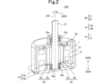
- FIG. 2 is a schematic perspective view showing brushless motor 100 with a part cut away.
- FIG. 3 is a perspective view of the magnetic core 1.
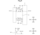
- FIG. 4 is a cross-sectional view of the magnetic core 1 and an enlarged cross-sectional view of the vicinity of the first curved surface portion R11.
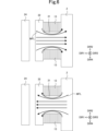
- FIG. 5 is a cross-sectional view showing the state of magnetic flux flowing through the magnetic core 50 according to the comparative example in a motor including the magnetic core 50 according to the comparative example.
- FIG. 6 is a cross-sectional view showing the state of magnetic flux flowing through magnetic core 1 in brushless motor 100. As shown in FIG. FIG. FIG.
- FIG. 7 is a cross-sectional view showing magnetic fluxes flowing through two adjacent magnetic cores 1 in brushless motor 100.
- FIG. 8 is a cross-sectional view showing an example of a manufacturing process for the magnetic core 1.
- FIG. 9 is a diagram showing the relationship between the radius of curvature CR1 of the first curved surface CS1 and the radius RA of the medium M.
- FIG. 10 is a cross-sectional view showing the inside of the barrel B during the finishing process.
- FIG. 11 is a perspective view of the magnetic core 1a.
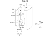
- FIG. 12 is a perspective view of the magnetic core 1b.
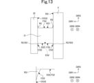
- FIG. 13 is a cross-sectional view of the magnetic core 1b and an enlarged cross-sectional view of the vicinity of the second curved surface portion R21.
- FIG. 14 is a diagram showing the relationship between the radius of curvature CR2 of the second curved surface CS2 and the radius RA of the medium M.
- Fig. 1 is an external perspective view of the brushless motor 100.
- Fig. 2 is a perspective schematic view showing the brushless motor 100 with a portion cut away.
- the directions are defined as follows, for example.
- the direction from the tooth tip 32 toward the rotation axis AR of the brushless motor 100 is defined as the first direction DIR1.
- the first direction DIR1 is the direction toward the rotation axis AR of the brushless motor 100 when the magnetic core 1 is assembled in the brushless motor 100.
- the direction in which the shaft 21 protrudes from the opening OP to the outside of the housing 15 is defined as the second direction DIR2.
- the clockwise direction with respect to the rotation axis AR of the brushless motor 100 when viewed in the second direction DIR2 is defined as the third direction DIR3.
- the opposite direction to the second direction DIR2 is defined as the fourth direction DIR4.
- the brushless motor 100 includes a rotor 20, a stator 10, a bearing 14, and a housing 15.
- the brushless motor 100 is an inner rotor type. That is, the stator 10 is disposed around the rotor 20.
- the brushless motor 100 is an example of a rotating electric machine of the present invention.
- the brushless motor 100 may also be an outer rotor type. That is, the rotor 20 may be disposed around the stator 10.
- the rotating electric machine may be configured so that the rotor rotates due to electricity.
- the rotating electric machine may be configured so that electricity is generated by the rotation of the rotor.
- Rotating electric machines include brushless motors, permanent magnet synchronous motors, permanent magnet synchronous generators, etc.
- the rotor 20 includes a shaft 21 and a rotor member 22.
- the shaft 21 is cylindrical.
- the rotor member 22 is cylindrical.
- the central axes of the shaft 21 and the rotor member 22 are aligned, and the central axes form a rotation axis AR.
- the rotor member 22 has a soft magnetic body 23 and a hard magnetic body 24.
- the rotor member 22 is attached to the outer peripheral surface of the shaft 21 in the radial direction centered on the rotation axis AR. More specifically, the soft magnetic body 23 is attached to the outer peripheral surface of the shaft 21 in the radial direction centered on the rotation axis AR.
- the hard magnetic body 24 is attached to the outer peripheral surface of the soft magnetic body 23 in the radial direction centered on the rotation axis AR.
- the soft magnetic material 23 is a soft magnetic material.
- the hard magnetic material 24 is a magnetized hard magnetic material. The hard magnetic material becomes magnetized when a magnetic field is applied from the outside. Even if the application of the magnetic field is then stopped, the hard magnetic material does not lose its magnetization.
- the bearing 14 supports the shaft 21 so that it can rotate in the circumferential direction around the rotation axis AR. More specifically, the bearing 14 has a first bearing 14a and a second bearing 14b.
- each of the first bearing 14a and the second bearing 14b is a ball bearing.
- Each of the first bearing 14a and the second bearing 14b is cylindrical and extends along the rotation axis AR.
- the central axis of each of the first bearing 14a and the second bearing 14b is the rotation axis AR. In other words, the central axis of each of the first bearing 14a and the second bearing 14b coincides with the central axis of the shaft 21. It should be noted that each of the first bearing 14a and the second bearing 14b is not limited to a ball bearing.
- the second bearing 14b is located in the fourth direction DIR4 from the first bearing 14a.
- the first bearing 14a is also located in the second direction DIR2 from the rotor member 22.
- the second bearing 14b is located in the fourth direction DIR4 from the rotor member 22.
- the second bearing 14b supports the end of the shaft 21 in the fourth direction DIR4.
- the housing 15 has a first housing 15a and a second housing 15b.
- the first housing 15a is cylindrical.
- the central axis of the first housing 15a is the rotation axis AR.
- the first housing 15a is located in the second direction DIR2 from the second housing 15b.
- the first housing 15a also has an opening OP.
- the shaft 21 protrudes from the opening OP in the second direction DIR2. That is, in this embodiment, the brushless motor 100 is a single-shaft type. Note that the brushless motor 100 is not limited to being a single-shaft type, and may be a double-shaft type.
- the first housing 15a supports the first bearing 14a, the multiple magnetic cores 1, and the multiple coils 13.
- the second housing 15b supports the second bearing 14b.
- the material of each of the first housing 15a and the second housing 15b is SUS (Stainless Used Steel).
- the material of each of the first housing 15a and the second housing 15b is not limited to SUS (Stainless Used Steel) and may be any material with high rigidity.
- the number of coils 13 and the number of magnetic cores 1 are each nine. Note that in FIG. 2, reference symbols are given only to representative magnetic cores 1 and coils 13 among the nine magnetic cores 1 and nine coils 13.
- the nine coils 13 and the nine magnetic cores 1 are lined up in the circumferential direction centered on the rotation axis AR.
- the nine magnetic cores 1 are arranged around the hard magnetic material 24 with a gap between them. Note that the number of coils 13 and the number of magnetic cores 1 are not limited to nine.
- the coil 13 is made of a conductive material such as copper.
- the coil 13 has a structure in which the surface of the copper wire is covered with an insulating coating. Since the surface of the copper wire is covered with an insulating coating, the coil 13 and the magnetic core 1 are electrically insulated. However, at the two end portions of the coil 13, the surface of the copper wire is not covered with an insulating coating and the copper wire is exposed.
- the coil 13 is supplied with current from a power source (not shown). When current flows through the coil 13, the coil 13 generates a magnetic field.
- the magnetic core 1 is magnetized by both the magnetic field generated by the hard magnetic material 24 and the magnetic field generated by the coil 13.
- the rotation of the rotor 20 is controlled by controlling the current supplied from the power source (not shown).
- Fig. 3 is a perspective view of the magnetic core 1.
- Fig. 4 is an enlarged cross-sectional view of the magnetic core 1 and the vicinity of the first curved surface forming portion R11. In Fig. 3, only the representative slope SL among the four slopes SL is given a reference symbol.
- the cross section of the magnetic core 1 in Fig. 4 is a plane that passes through the first flat surface FS1 of the first end surface ES1 of the tooth main body portion 31 and is perpendicular to the first flat surface FS1 of the first end surface ES1 of the tooth main body portion 31.
- the magnetic core 1 includes a core back portion 2 and a teeth portion 3.
- the core back portion 2 and the teeth portion 3 are included in the magnetic core 1, which is a single member.
- a single member means a member that has a structure that cannot be separated without being damaged.
- the magnetic core 1 is a soft magnetic material.
- the magnetic core 1 is a molded body formed from soft magnetic powder. That is, each of the core back portion 2 and the teeth portion 3 is a molded body formed from soft magnetic powder.
- the material of the soft magnetic powder includes, for example, iron and a binder.
- the binder is, for example, a resin.
- the soft magnetic powder is, for example, a mixture of iron powder and epoxy resin powder, which is an example of binder powder.
- Such a magnetic core 1 is produced, for example, by compression molding.
- an insulating film (not shown) is applied to the surface of the magnetic core 1 that comes into contact with another member. Note that the magnetic core 1 does not have to be a molded body formed from soft magnetic powder.
- the core back portion 2 has a front surface IS2 facing in the first direction DIR1, a back surface OS2 facing in the opposite direction to the first direction DIR1, two side surfaces connecting the front surface IS2 and the back surface OS2, which are aligned in the third direction DIR3, and two end surfaces connecting the front surface IS2 and the back surface OS2, which are aligned in the second direction DIR2.
- the front surface IS2, the two side surfaces aligned in the third direction DIR3, and the two end surfaces aligned in the second direction DIR2 are each flat.
- the front surface IS32 is a curved surface that is concavely curved in the opposite direction to the first direction DIR1.
- the back surface OS2 is a curved surface that is convexly curved in the opposite direction to the first direction DIR1.
- the back surface OS2 forms part of the outer peripheral surface of the stator 10.
- the side connecting the front surface IS2 and the back surface OS2 is magnetically connected to the side connecting the front surface IS2 and the back surface OS2 of the adjacent magnetic core 1.
- the front surface IS2, the two side surfaces aligned in the third direction DIR3, and the two end surfaces aligned in the second direction DIR2 may each include at least a portion of a curved surface.
- the back surface OS2 may also include at least a portion of a flat surface.
- the teeth portion 3 has a shape extending in the first direction DIR1 from the core back portion 2. More specifically, the teeth portion 3 has a teeth main body portion 31 extending in the first direction DIR1 from the front surface IS2, and a teeth tip portion 32 provided at the tip of the teeth main body portion 31. As shown in FIG. 2, a coil 13 is wound around the teeth main body portion 31. When the magnetic core 1 is incorporated into the brushless motor 100, the teeth tip portion 32 faces the hard magnetic material 24 of the rotor 20 via a gap (air gap). In this embodiment, the position in the second direction DIR2 of the end of the rotor member 22 in the second direction DIR2 is equal to the position in the second direction DIR2 of the end of the teeth main body portion 31 in the second direction DIR2.
- the position of the end of the rotor member 22 in the fourth direction DIR4 is equal to the position of the end of the tooth main body 31 in the fourth direction DIR4.
- the position of the end of the rotor member 22 in the second direction DIR2 does not have to be equal to the position of the end of the tooth main body 31 in the second direction DIR2.
- the position of the end of the rotor member 22 in the fourth direction DIR4 does not have to be equal to the position of the end of the tooth main body 31 in the fourth direction DIR4.
- the tooth tip portion 32 has a front surface IS32 facing in the first direction DIR1, a back surface OS32 facing in the opposite direction to the first direction DIR1, two side surfaces connecting the front surface IS32 and the back surface OS32, which are aligned in the third direction DIR3, and two end surfaces connecting the front surface IS32 and the back surface OS32, which are aligned in the second direction DIR2.
- the back surface OS32, the two side surfaces aligned in the third direction DIR3, and the two end surfaces aligned in the second direction DIR2 are all flat surfaces.
- the front surface IS32 is a curved surface that is concavely curved in the first direction DIR1.
- the front surface IS32 follows the outer peripheral surface of the rotor 20.
- the rear surface OS32, the two side surfaces aligned in the third direction DIR3, and the two end surfaces aligned in the second direction DIR2 may each include a curved surface.
- the front surface IS32 may also include a flat surface.
- the teeth main body portion 31 has a shape in which each corner of a rectangular prism extending in the first direction DIR1 is chamfered. More specifically, as shown in FIG. 4, the teeth main body portion 31 has a first end face ES1 facing the second direction DIR2, a second end face ES2 facing the fourth direction DIR4, a first side face SS1 facing the third direction DIR3, a second side face SS2 facing the opposite direction to the third direction DIR3, and four inclined faces SL connecting the first end face ES1 or the second end face ES2 to the first side face SS1 or the second side face SS2.
- each of the first end face ES1 and the second end face ES2 includes a first flat surface FS1 that is a surface parallel to the first direction DIR1.
- Each of the first side surface SS1 and the second side surface SS2 includes a second flat surface FS2 that is a surface parallel to the first direction DIR1.
- each of the first end surface ES1 and the second end surface ES2 does not have to include the first flat surface FS1 that is a surface parallel to the first direction DIR1.
- each of the first side surface SS1 and the second side surface SS2 does not have to include the second flat surface FS2 that is a surface parallel to the first direction DIR1.
- the first end surface ES1 or the second end surface ES2 corresponds to the "end surface” in the present invention.
- the first side surface SS1 or the second side surface SS2 corresponds to the "side surface” in the present invention.
- the outer edge of the teeth main body portion 31 is surrounded by the outer edge of the core back portion 2. Furthermore, when the magnetic core 1 is viewed in the first direction DIR1, the outer edge of the teeth main body portion 31 is surrounded by the outer edge of the teeth tip portion 32. Note that the teeth main body portion 31 does not have to have a shape in which each corner of the rectangular prism extending in the first direction DIR1 is chamfered.
- four first curved surface forming portions R1 are formed on the tooth main body portion 31.
- the four first curved surface forming portions R1 are part of the tooth main body portion 31.
- One of the four first curved surface forming portions R1 is formed at an end portion of the tooth main body portion 31 in the first direction DIR1 and at an end portion of the tooth main body portion 31 in the second direction DIR2.
- One of the four first curved surface forming portions R1 is formed at an end portion of the tooth main body portion 31 in the opposite direction to the first direction DIR1 and at an end portion of the tooth main body portion 31 in the second direction DIR2.
- One of the four first curved surface forming portions R1 is formed at an end portion of the tooth main body portion 31 in the first direction DIR1 and at an end portion of the tooth main body portion 31 in the fourth direction DIR4.
- One of the four first curved surface forming portions R1 is formed at an end portion of the tooth main body portion 31 in the opposite direction to the first direction DIR1 and at an end portion of the tooth main body portion 31 in the fourth direction DIR4.
- the four first curved surface forming portions R1 have a mutually symmetrical structure. Therefore, a description of the two first curved surface forming portions R1 formed at the end portion of the tooth main body portion 31 in the fourth direction DIR4 will be omitted. Note that the number of first curved surface forming portions R1 does not have to be four. Also, the first curved surface forming portions R1 do not have to have a mutually symmetrical structure.
- first curved surface forming portion R1 that is formed on the end of the tooth main body portion 31 in the first direction DIR1 and on the end of the tooth main body portion 31 in the second direction DIR2.
- this first curved surface forming portion R1 will be referred to as the first curved surface forming portion R11.
- the first curved surface forming portion R11 protrudes from the first flat surface FS1 of the first end surface ES1 toward the second direction DIR2.
- the first curved surface forming portion R11 is located only on the second direction DIR2 side of the first flat surface FS1 of the first end surface ES1. More specifically, the first curved surface forming portion R11 has a first curved surface CS1.
- the first curved surface CS1 of the first curved surface forming portion R11 is curved in a concave shape.
- the first curved surface CS1 of the first curved surface forming portion R11 is curved in an arc shape in a cross section perpendicular to the third direction DIR3.
- the first curved surface CS1 of the first curved surface forming portion R11 has one radius of curvature CR1.
- the first curved surface CS1 of the first curved surface forming portion R11 does not have to be curved in an arc shape in a cross section perpendicular to the third direction DIR3.
- the first curved surface CS1 of the first curved surface forming portion R11 may have multiple radii of curvature CR1.
- the first curved surface CS1 of the first curved surface forming portion R11 is part of the first end surface ES1.
- the first curved surface CS1 of the first curved surface forming portion R11 is smoothly connected to the back surface OS32 of the tooth tip portion 32. Therefore, the tooth main body portion 31 is smoothly connected to the back surface OS32 of the tooth tip portion 32 via the first curved surface CS1 of the first curved surface forming portion R11.
- an edge E is formed at the end of the first curved surface CS1 of the first curved surface forming portion R11 in the third direction DIR3, and at the end of the first curved surface CS1 of the first curved surface forming portion R11 in the opposite direction to the third direction DIR3.
- first curved surface forming portion R1 that is formed on the end of the tooth main body portion 31 in the opposite direction to the first direction DIR1 and on the end of the tooth main body portion 31 in the second direction DIR2.
- this first curved surface forming portion R1 will be referred to as the first curved surface forming portion R12.
- the first curved surface forming portion R12 protrudes from the first flat surface FS1 of the first end face ES1 toward the second direction DIR2. Moreover, the first curved surface forming portion R12 is located only on the second direction DIR2 side of the first flat surface FS1 of the first end face ES1. More specifically, the first curved surface forming portion R12 has a first curved surface CS1.
- the first curved surface CS1 of the first curved surface forming portion R12 is curved in a concave shape.
- the first curved surface CS1 of the first curved surface forming portion R12 is curved in an arc shape in a cross section perpendicular to the third direction DIR3.
- the first curved surface CS1 of the first curved surface forming portion R12 has one radius of curvature CR1.
- the first curved surface CS1 of the first curved surface forming portion R12 does not have to be curved in an arc shape in a cross section perpendicular to the third direction DIR3.
- the first curved surface CS1 of the first curved surface forming portion R12 may have multiple radii of curvature CR1.
- the first curved surface CS1 of the first curved surface forming portion R12 is part of the first end surface ES1.
- the first curved surface CS1 of the first curved surface forming portion R12 is smoothly connected to the front surface IS2 of the core back portion 2. Therefore, the tooth main body portion 31 is smoothly connected to the front surface IS2 of the core back portion 2 via the first curved surface CS1 of the first curved surface forming portion R12.
- an edge E is formed at the end of the first curved surface CS1 of the first curved surface forming portion R12 in the third direction DIR3, and at the end of the first curved surface CS1 of the first curved surface forming portion R12 in the opposite direction to the third direction DIR3.
- the magnetic core 1 can mitigate the occurrence of magnetic saturation.
- a magnetic core 50 in which the first curved surface forming portion R1 is not formed in the tooth main body portion 31 will be described with reference to the drawings.
- FIG. 5 is a cross-sectional view showing the state of magnetic flux flowing in the magnetic core 50 according to the comparative example in a motor equipped with the magnetic core 50 according to the comparative example. Note that in FIG. 5, only representative magnetic field lines MFL out of the multiple magnetic field lines MFL are given reference symbols. Also, for the sake of explanation, the boundary line between the tooth main body portion 31 and the core back portion 2, and the boundary line between the tooth main body portion 31 and the tooth tip portion 32 have been omitted in FIG. 5.
- the brushless motor 100 when current is applied to the coil 13 wound around the tooth main body 31, magnetic flux is generated in the tooth main body 31.
- This magnetic flux flows from the tooth main body 31 toward the front surface IS2 of the core back portion 2 or the back surface OS32 of the tooth tip portion 32.
- the direction of the magnetic flux can be changed by changing the direction of the current flowing through the coil 13.
- the magnetic flux tries to flow through the shortest path inside the magnetic core 50 of the comparative example.
- corners A are formed at the portions where the first end surface ES1 of the tooth main body 31 is connected to the front surface IS2 of the core back portion 2 and the back surface OS2 of the tooth tip portion 32.
- the flow of magnetic flux was impeded by corner A, and the magnetic flux was forced to take a detour near corner A, making it difficult to flow.
- residual stress was generated near corner A, increasing the magnetic resistance in the magnetic circuit and causing localized magnetic saturation at corner A.
- the output torque of the motor could not be improved.
- FIG. 6 is a cross-sectional view showing the magnetic flux flowing through the magnetic core 1 in the brushless motor 100. Note that for the sake of explanation, the boundary between the teeth main body portion 31 and the core back portion 2, and the boundary between the teeth main body portion 31 and the teeth tip portion 32 have been omitted in FIG. 6. Also, in FIG. 6, only representative magnetic field lines MFL out of the multiple magnetic field lines MFL are given reference symbols.
- the tooth main body 31 is formed with a first curved surface forming portion R11 having a concavely curved first curved surface CS1.
- the first curved surface CS1 of the first curved surface forming portion R11 is smoothly connected to the back surface OS32 of the tooth tip 32.
- the first curved surface forming portion R11 is formed in the tooth main body 31, so that in the vicinity of the first curved surface forming portion R11, the magnetic flux can flow along the shortest path without detours. Therefore, in the magnetic core 1, the magnetic flux flows more easily in the vicinity of the first curved surface forming portion R11 than in the magnetic core 50 according to the comparative example. This makes it possible to mitigate the occurrence of magnetic saturation in the vicinity of the first curved surface forming portion R11.
- the magnetic core 1 can better receive the magnetic flux generated by the hard magnetic body 24 and including a component in the second direction DIR2 or the fourth direction DIR4.
- This effect becomes more pronounced when the end of the rotor member 22 in the second direction DIR2 is located in the second direction DIR2 further from the end of the teeth main body portion 31 in the second direction DIR2 and the distance in the second direction DIR2 between the end of the rotor member 22 in the second direction DIR2 and the end of the teeth main body portion 31 in the second direction DIR2 is longer, or when the end of the rotor member 22 in the fourth direction DIR4 is located in the fourth direction DIR4 further from the end of the teeth main body portion 31 in the fourth direction DIR4 and the distance in the fourth direction DIR4 between the end of the rotor member 22 in the fourth direction DIR4 and the end of the teeth main body portion 31 in the fourth direction DIR4 is longer.
- the coil 13 can be wound more around the tooth main body portion 31 than when the first curved surface CS1 of the first curved surface forming portion R11 is curved convexly. This increases the slot occupancy rate of the coil 13, and improves the output torque of the brushless motor 100.
- the first curved surface forming portion R11 protrudes in the second direction DIR2 from the first flat surface FS1 of the first end face ES1 toward the second direction DIR2, and is located only on the second direction DIR2 side of the first flat surface FS1 of the first end face ES1.
- the first curved surface forming portion R11 is formed without reducing the cross-sectional area of the teeth main body portion 31 in the second direction DIR2. Therefore, even if the first curved surface forming portion R11 is formed, the saturation magnetic flux density of the magnetic flux flowing inside the teeth main body portion 31 does not decrease. Therefore, a decrease in the output torque of the brushless motor 100 can be suppressed.
- the tooth main body 31 is formed with a first curved surface forming portion R12 having a concavely curved first curved surface CS1.
- the first curved surface CS1 of the first curved surface forming portion R12 is smoothly connected to the front surface IS2 of the core back portion 2. Because the tooth main body 31 is formed with the first curved surface forming portion R12, magnetic flux can flow along the shortest path without detours in the vicinity of the first curved surface forming portion R12. Therefore, in the magnetic core 1, magnetic flux flows more easily in the vicinity of the first curved surface forming portion R12 than in the magnetic core 50 of the comparative example. This makes it possible to mitigate the occurrence of magnetic saturation in the vicinity of the first curved surface forming portion R12.
- the coil 13 can be wound more around the tooth main body portion 31 than when the first curved surface CS1 of the first curved surface forming portion R12 is curved convexly. This increases the slot space factor of the coil 13, and improves the output torque of the brushless motor 100.
- the area in which magnetic flux flows can be expanded in the direction perpendicular to the first direction DIR1 for the core back portion 2. More specifically, when the magnetic core 1 is incorporated into the brushless motor 100, adjacent magnetic cores 1 are connected by their respective core back portions 2. Hereinafter, one of the adjacent magnetic cores 1 will be referred to as magnetic core 11, and the other as magnetic core 12.
- the first curved surface forming portion R1 is not formed on the core back portion 2 side of the teeth main body portion 31, so that an angle A is formed at the portion where the first end face ES1 of the teeth main body portion 31 and the front face IS2 of the core back portion 2 are connected.
- This angle A prevents the flow of magnetic flux from spreading in the second direction DIR2 and fourth direction DIR4, and the area where magnetic flux flows cannot be expanded in the second direction DIR2 and fourth direction DIR4 for the core back portion 2, and the core back portion 2 cannot be effectively used as a magnetic circuit. If the area through which the magnetic flux flows cannot be expanded, this leads to an increase in magnetic resistance in the magnetic circuit, which causes a decrease in the output efficiency of the motor when the magnetic core 50 according to the comparative example is used in the motor.
- FIG. 7 is a cross-sectional view showing the magnetic flux flowing through two adjacent magnetic cores 1 in the brushless motor 100. Note that in FIG. 7, only representative magnetic field lines MFL out of the multiple magnetic field lines MFL are labeled with reference symbols.
- the first curved surface forming portion R12 is formed on the tooth main body portion 31, so that the flow of magnetic flux is not hindered by corners near the first curved surface forming portion R12, and the magnetic flux is likely to spread in the second direction DIR2.
- the first curved surface forming portion R12 is formed on the tooth main body portion 31, so that the flow of magnetic flux is not hindered by corners near the first curved surface forming portion R12, and the magnetic flux is likely to spread in the second direction DIR2.
- the magnetic flux is likely to exit toward the magnetic core 12, and in the magnetic core 12, the magnetic flux is likely to enter from the magnetic core 11. This makes it possible to suppress an increase in magnetic resistance in the magnetic circuit. Therefore, it is possible to suppress a decrease in the output efficiency of the brushless motor 100.
- the first curved surface forming portion R12 protrudes in the second direction DIR2 from the first flat surface FS1 of the first end face ES1 toward the second direction DIR2, and is located only on the second direction DIR2 side of the first flat surface FS1 of the first end face ES1.
- the first curved surface forming portion R12 is formed without reducing the cross-sectional area of the teeth main body portion 31 in the second direction DIR2. Therefore, even if the first curved surface forming portion R12 is formed, the saturation magnetic flux density of the magnetic flux flowing inside the teeth main body portion 31 does not decrease. Therefore, a decrease in the output torque of the brushless motor 100 can be suppressed.
- Fig. 8 is a cross-sectional view showing an example of a manufacturing process of the magnetic core 1.
- Fig. 9 is a diagram showing the relationship between the radius of curvature CR1 of the first curved surface CS1 and the radius RA of the medium M. In Fig. 9, only a representative first curved surface CS1 among the four first curved surfaces CS1 is given a reference symbol.
- Fig. 10 is a cross-sectional view showing the inside of the barrel B in the finishing process.
- the soft magnetic powder SMP which is a mixture of iron powder and epoxy resin powder
- the soft magnetic powder SMP filled in the mold DI is pressed by the punch P to compression mold the soft magnetic powder SMP.
- the punch P has a convexly curved convex surface CON.
- the number of convex surfaces CON is four.
- the radius of curvature CR1 of the first curved surface CS1 of the compression molded soft magnetic powder SMP is greater than the radius RA of the media M.
- the minimum value of the multiple radii of curvature CR1 should be greater than the radius RA of the media M.
- a finishing process is performed in which the magnetic core 1 is polished.
- the compression molded soft magnetic powder SMP, media M, a grinding aid (not shown), and water W are first placed inside a hollow barrel B.
- the media M has a spherical shape with a radius RA.
- the number of compression molded soft magnetic powder SMP and media M is one, but the number of compression molded soft magnetic powder SMP and media M may be multiple.
- the magnetic core 1 can be finished efficiently.
- multiple magnetic cores 1 can be finished simultaneously.
- the barrel B is rotated to bring the media M into contact with the compression-molded soft magnetic powder SMP, and the compression-molded soft magnetic powder SMP is polished.
- the compression-molded soft magnetic powder SMP is polished with the media M, thereby removing burrs formed on the surface of the compression-molded soft magnetic powder SMP in the previous stage of the finishing process, and the magnetic core 1 is finished.
- the method of polishing the compression-molded soft magnetic powder SMP with the media M in the finishing process is not limited to rotating the barrel B, and may be by vibrating the barrel B.
- the barrel B is not essential in the finishing process, and it is sufficient to polish the compression-molded soft magnetic powder SMP with the media M.
- the polishing aid and water W are not essential in the finishing process.
- the magnetic core 1 is a molded body made from soft magnetic powder. Therefore, as shown in the manufacturing method of the magnetic core 1 above, the first curved surface forming portion R1 can be easily formed compared to when the magnetic core is formed by laminating electromagnetic steel sheets. As a result, the magnetic core 1 can be easily manufactured.
- burrs formed on the first curved surface CS1 before the finishing process can be removed in the finishing process. More specifically, the radius of curvature CR1 of the first curved surface CS1 of the compression-molded soft magnetic powder SMP is larger than the radius RA of the media M. This allows the media M to contact every corner of the first curved surface CS1 in the finishing process, and burrs formed on the first curved surface CS1 prior to the finishing process can be removed in the finishing process. This makes it possible to prevent damage to the coil 13 when it is wound around the tooth main body portion 31 after the magnetic core 1 is completed.
- the insulating film when applying an insulating film to the surface of the magnetic core 1 after the finishing process, the insulating film can be made thinner since there are no burrs. This increases the slot occupancy rate of the coil 13, and improves the output efficiency of the brushless motor 100.
- FIG. 11 is a perspective view of the magnetic core 1a.
- Fig. 11 only representative first curved surface forming portions R1 and first curved surfaces CS1 among the four first curved surface forming portions R1 and the four first curved surfaces CS1 are given reference symbols.
- the magnetic core 1a according to the first modified example only the parts different from the magnetic core 1 according to the first embodiment will be described, and the rest will be omitted.
- magnetic core 1a differs from magnetic core 1 in that four third curved surface forming portions R3 are formed on tooth main body portion 31.
- the four third curved surface forming portions R3 are part of the tooth main body portion 31.
- One of the four third curved surface forming portions R3 is formed at an end portion of the tooth main body portion 31 in the opposite direction to the third direction DIR3 and at an end portion of the tooth main body portion 31 in the second direction DIR2.
- One of the four third curved surface forming portions R3 is formed at an end portion of the tooth main body portion 31 in the opposite direction to the third direction DIR3 and at an end portion of the tooth main body portion 31 in the fourth direction DIR4.
- One of the four third curved surface forming portions R3 is formed at an end portion of the tooth main body portion 31 in the third direction DIR3 and at an end portion of the tooth main body portion 31 in the second direction DIR2.
- One of the four third curved surface forming portions R3 is formed at an end portion of the tooth main body portion 31 in the third direction DIR3 and at an end portion of the tooth main body portion 31 in the fourth direction DIR4.
- the four third curved surface forming portions R3 have a mutually symmetrical structure. Note that the number of third curved surface forming portions R3 does not have to be four. Also, the third curved surface forming portions R3 do not have to have a mutually symmetrical structure.
- Each of the four third curved surface forming portions R3 has a third curved surface CS3.
- the third curved surface CS3 of each of the four third curved surface forming portions R3 is a part of each of the four inclined surfaces SL.
- the third curved surface CS3 of each of the four third curved surface forming portions R3 is tapered. More specifically, the third curved surface CS3 of each of the four third curved surface forming portions R3 is tapered on the core back portion 2 side of the tooth main body portion 31 as it approaches the core back portion 2. Also, the third curved surface CS3 of each of the four third curved surface forming portions R3 is tapered on the tooth tip portion 32 side of the tooth main body portion 31 as it approaches the tooth tip portion 32.
- the third curved surface CS3 is smoothly connected to the edge E of the first curved surface CS1 in the third direction DIR3.
- the magnetic core 1a as described above also has the same effect as the magnetic core 1. Furthermore, in the magnetic core 1a, the third curved surface forming portion R3 is formed on the tooth main body portion 31, so that the flow of magnetic flux is not impeded by corners and is facilitated at the portion where the first end face ES1 or the second end face ES2 of the tooth main body portion 31 connects to the first side face SS1 or the second side face SS2 on the core back 2 portion side or the tooth tip portion 32 side of the tooth main body portion 31. This can further mitigate the occurrence of localized magnetic saturation.
- FIG. 12 is a perspective view of the magnetic core 1b.
- FIG. 13 is a cross-sectional view of the magnetic core 1b and an enlarged cross-sectional view of the vicinity of the second curved surface forming portion R21.
- the cross-section of the magnetic core 1b in FIG. 13 is a plane that passes through the second flat surface FS2 of the second side surface SS2 of the tooth main body portion 31 and is perpendicular to the second flat surface FS2 of the second side surface SS2 of the tooth main body portion 31.
- FIG. 14 is a diagram showing the relationship between the curvature radius CR2 of the second curved surface CS2 and the radius RA of the media M.
- FIG. 14 only the representative second curved surface CS2 among the four second curved surfaces CS2 is given a reference symbol.
- the magnetic core 1b according to the second modified example only the parts different from the magnetic core 1a according to the first modified example will be described, and the rest will be omitted.
- magnetic core 1b differs from magnetic core 1a in that four second curved surface forming portions R2 are formed on tooth body portion 31.
- the four second curved surface forming portions R2 are part of the tooth main body portion 31.
- One of the four second curved surface forming portions R2 is formed at an end of the tooth main body portion 31 in the first direction DIR1 and at an end of the tooth main body portion 31 in the opposite direction to the third direction DIR3.
- One of the four second curved surface forming portions R2 is formed at an end of the tooth main body portion 31 in the opposite direction to the first direction DIR1 and at an end of the tooth main body portion 31 in the opposite direction to the third direction DIR3.
- One of the four second curved surface forming portions R2 is formed at an end of the tooth main body portion 31 in the first direction DIR1 and at an end of the tooth main body portion 31 in the third direction DIR3.
- One of the four second curved surface forming portions R2 is formed at an end of the tooth main body portion 31 in the opposite direction to the first direction DIR1 and at an end of the tooth main body portion 31 in the third direction DIR3.
- the four second curved surface forming portions R2 have a symmetrical structure with respect to each other. Therefore, a description of the two second curved surface forming portions R2 formed at the ends of the tooth main body portion 31 in the third direction DIR3 will be omitted. Note that the number of second curved surface forming portions R2 does not have to be four. Also, the second curved surface forming portions R2 do not have to have a symmetrical structure with respect to each other.
- this second curved surface forming portion R2 that is formed on the end of the tooth main body portion 31 in the first direction DIR1 and on the end of the tooth main body portion 31 in the opposite direction to the third direction DIR3.
- this second curved surface forming portion R2 will be referred to as the second curved surface forming portion R21.
- the second curved surface forming portion R21 protrudes from the second flat surface FS2 of the second side surface SS2 in the opposite direction of the third direction DIR3. Moreover, the second curved surface forming portion R21 is located only on the opposite side of the third direction DIR3 from the second flat surface FS2 of the second side surface SS2. More specifically, the second curved surface forming portion R21 has a second curved surface CS2.
- the second curved surface CS2 of the second curved surface forming portion R21 is curved in a concave shape.
- the second curved surface CS2 of the second curved surface forming portion R21 is curved in an arc shape in a cross section perpendicular to the second direction DIR2.
- the second curved surface CS2 of the second curved surface forming portion R21 has one radius of curvature CR2.
- the second curved surface CS2 of the second curved surface forming portion R21 does not have to be curved in an arc shape in a cross section perpendicular to the second direction DIR2.
- the second curved surface CS2 of the second curved surface forming portion R21 may have multiple radii of curvature CR2.
- the second curved surface CS2 of the second curved surface forming portion R21 is part of the second side surface SS2.
- the second curved surface CS2 of the second curved surface forming portion R21 is smoothly connected to the back surface OS32 of the tooth tip portion 32. Therefore, the tooth main body portion 31 is connected to the back surface OS32 of the tooth tip portion 32 via the second curved surface CS2 of the second curved surface forming portion R21.
- this second curved surface forming portion R2 that is formed on the end of the tooth main body portion 31 in the opposite direction to the first direction DIR1 and the end of the tooth main body portion 31 in the opposite direction to the third direction DIR3.
- this second curved surface forming portion R2 will be referred to as the second curved surface forming portion R22.
- the second curved surface forming portion R22 protrudes from the second flat surface FS2 of the second side surface SS2 in the opposite direction of the third direction DIR3. Moreover, the second curved surface forming portion R22 is located only on the opposite side of the third direction DIR3 from the second flat surface FS2 of the second side surface SS2. More specifically, the second curved surface forming portion R22 has a second curved surface CS2.
- the second curved surface CS2 of the second curved surface forming portion R22 is curved in a concave shape.
- the second curved surface CS2 of the second curved surface forming portion R22 is curved in an arc shape in a cross section perpendicular to the second direction DIR2.
- the second curved surface CS2 of the second curved surface forming portion R21 has one radius of curvature CR2.
- the second curved surface CS2 of the second curved surface forming portion R22 does not have to be curved in an arc shape in a cross section perpendicular to the second direction DIR2.
- the second curved surface CS2 of the second curved surface forming portion R22 may have multiple radii of curvature CR2.
- the second curved surface CS2 of the second curved surface forming portion R22 is part of the second side surface SS2.
- the second curved surface CS2 of the second curved surface forming portion R22 is smoothly connected to the front surface IS2 of the core back portion 2. Therefore, the tooth main body portion 31 is smoothly connected to the front surface IS2 of the core back portion 2 via the second curved surface CS2 of the second curved surface forming portion R22.
- the manufacturing method of the magnetic core 1b according to this modified example is the same as the manufacturing method of the magnetic core 1 according to the first embodiment.
- the radius of curvature CR2 of the second curved surface CS2 of the compression-molded soft magnetic powder SMP is larger than the radius RA of the media M.
- the second curved surface CS2 of the compression-molded soft magnetic powder SMP has multiple radii of curvature CR2, it is sufficient that the minimum value of the multiple radii of curvature CR2 is larger than the radius RA of the media M.
- the magnetic core 1b as described above also has the same effect as the magnetic core 1a.
- the tooth main body 31 is formed with a second curved surface forming portion R21 having a concavely curved second curved surface CS2.
- the second curved surface CS2 of the second curved surface forming portion R21 is smoothly connected to the back surface OS32 of the tooth tip portion 32. Since the second curved surface forming portion R21 is formed in the tooth main body 31, the magnetic flux can flow in the shortest path without detours in the vicinity of the second curved surface forming portion R21. Therefore, in the magnetic core 1b, the magnetic flux flows more easily in the vicinity of the second curved surface forming portion R21 than in the magnetic core 50 according to the comparative example. This makes it possible to mitigate the occurrence of magnetic saturation in the vicinity of the second curved surface forming portion R21.
- the coil 13 can be wound more around the tooth main body portion 31 than when the second curved surface CS2 of the second curved surface forming portion R21 is curved convexly. This increases the slot space factor of the coil 13, and improves the output torque of the brushless motor 100.
- the second curved surface forming portion R21 protrudes from the second flat surface FS2 of the second side surface SS2 in the opposite direction of the third direction DIR3, and is located only on the opposite side of the third direction DIR3 from the second flat surface FS2 of the second side surface SS2.
- the second curved surface forming portion R21 is formed without reducing the cross-sectional area of the teeth main body portion 31 in the opposite direction of the third direction DIR3. Therefore, even if the second curved surface forming portion R21 is formed, the saturation magnetic flux density of the magnetic flux flowing inside the teeth main body portion 31 does not decrease. Therefore, a decrease in the output torque of the brushless motor 100 can be suppressed.
- tooth main body 31 is formed with a second curved surface forming portion R22 having a concavely curved second curved surface CS2.
- the second curved surface CS2 of second curved surface forming portion R22 is smoothly connected to the front surface IS2 of core back portion 2. Because tooth main body 31 is formed with second curved surface forming portion R22, magnetic flux can flow along the shortest path without detours in the vicinity of second curved surface forming portion R22. Therefore, in magnetic core 1b, magnetic flux flows more easily in the vicinity of second curved surface forming portion R22 than in magnetic core 50 according to the comparative example. This makes it possible to mitigate the occurrence of magnetic saturation in the vicinity of second curved surface forming portion R22.
- the coil 13 can be wound more around the tooth main body portion 31 than when the second curved surface CS2 of the second curved surface forming portion R22 is curved convexly. This increases the slot space factor of the coil 13, and improves the output torque of the brushless motor 100.
- the manufacturing method of the magnetic core 1b allows burrs formed on the second curved surface CS2 before the finishing process to be removed in the finishing process. More specifically, the radius of curvature CR2 of the second curved surface CS2 of the compression-molded soft magnetic powder SMP is larger than the radius RA of the media M. This allows the media M to contact every corner of the second curved surface CS2 in the finishing process, and allows burrs formed on the second curved surface CS2 prior to the finishing process to be removed in the finishing process. This makes it possible to prevent damage to the coil 13 when it is wound around the tooth main body portion 31 after the magnetic core 1b is completed.
- the magnetic core according to the present invention is not limited to the magnetic core 1, the magnetic core 1a, or the magnetic core 1b, and may be modified within the scope of the present invention.
- the structures of the magnetic core 1, the magnetic core 1a, or the magnetic core 1b may be arbitrarily combined.
- the rotating electric machine may include a magnetic core 1, a magnetic core 1a, or a magnetic core 1b, and may include a brush.
- the present invention has the following configuration.
- a magnetic core for use in a rotating electrical machine comprising: a core back portion having a front surface that faces a first direction toward a rotation shaft of the rotating electric machine when the magnetic core is assembled in the rotating electric machine; Teeth portion, Equipped with The teeth portion includes: a teeth main body portion extending in the first direction from the front surface; a tooth tip portion provided at a tip of the tooth main body portion; Including, The tip end of the tooth has a back surface facing a direction opposite to the first direction, the teeth main body portion has an end surface that faces a second direction along the rotation axis when the magnetic core is assembled in the rotating electric machine, The end surface has a concave curved surface that smoothly connects the end surface to the front surface of the core back portion or the back surface of the tooth tip portion, and the curved surface is formed by a first curved surface forming portion that is a part of the tooth main body portion.
- Magnetic core Magnetic core.
- the end surface includes a first flat surface that is a surface parallel to the first direction, The first curved surface forming portion protrudes from the first flat surface in the second direction and is located only on the second direction side of the first flat surface.
- the teeth main body portion has a side surface facing a circumferential direction about the rotation axis when the magnetic core is assembled in the rotating electric machine,
- the side surface has a concave curved surface that smoothly connects the side surface to the front surface of the core back portion or the back surface of the tooth tip portion, and the curved surface is formed by a second curved surface forming portion that is a part of the tooth main body portion.
- the side surface includes a second flat surface that is a surface parallel to the first direction, The second curved surface forming portion protrudes from the second flat surface in the circumferential direction and is located only on the circumferential direction side of the second flat surface.
- the teeth main body portion has a side surface facing a third direction which is a circumferential direction about the rotation axis when the magnetic core is assembled into the rotating electric machine, and an inclined surface connecting the end face and the side surface,
- the inclined surface has a tapered curved surface that smoothly connects the inclined surface to an edge of the curved surface in the third direction, and the tapered curved surface is formed by a third curved surface forming portion that is a part of the tooth main body.
- a compact formed from soft magnetic powder A magnetic core according to any one of (1) to (5).
- a magnetic core according to any one of (1) to (6) is provided. Rotating electrical machines.
- the method includes a finishing step of polishing the magnetic core according to any one of (1) to (6) by using a spherical media, Prior to the finishing step, the magnetic core is manufactured so that the radius of curvature of the curved surface of the end face is already larger than the diameter of the media used in the finishing step.
- a manufacturing method for a magnetic core Prior to the finishing step, the magnetic core is manufactured so that the radius of curvature of the curved surface of the end face is already larger than the diameter of the media used in the finishing step.
- the method includes a finishing step of polishing the magnetic core according to (3) or (4) using a spherical media, Prior to the finishing step, the magnetic core is manufactured so that the radius of curvature of the curved surface of the side surface is already larger than the diameter of the media used in the finishing step.
- a manufacturing method for a magnetic core is described in detail below.
Landscapes
- Engineering & Computer Science (AREA)
- Power Engineering (AREA)
- Manufacturing & Machinery (AREA)
- Iron Core Of Rotating Electric Machines (AREA)
Priority Applications (3)
| Application Number | Priority Date | Filing Date | Title |
|---|---|---|---|
| CN202480003797.2A CN119895696A (zh) | 2023-08-25 | 2024-07-25 | 磁芯及其制造方法、带线圈的磁芯和旋转电气机械 |
| JP2025517135A JPWO2025047230A1 (https=) | 2023-08-25 | 2024-07-25 | |
| US19/081,484 US20250211035A1 (en) | 2023-08-25 | 2025-03-17 | Magnetic core and method for manufacturing the same, magnetic core with coil, and rotary electric machine |
Applications Claiming Priority (2)
| Application Number | Priority Date | Filing Date | Title |
|---|---|---|---|
| JP2023-136919 | 2023-08-25 | ||
| JP2023136919 | 2023-08-25 |
Related Child Applications (1)
| Application Number | Title | Priority Date | Filing Date |
|---|---|---|---|
| US19/081,484 Continuation US20250211035A1 (en) | 2023-08-25 | 2025-03-17 | Magnetic core and method for manufacturing the same, magnetic core with coil, and rotary electric machine |
Publications (1)
| Publication Number | Publication Date |
|---|---|
| WO2025047230A1 true WO2025047230A1 (ja) | 2025-03-06 |
Family
ID=94818806
Family Applications (1)
| Application Number | Title | Priority Date | Filing Date |
|---|---|---|---|
| PCT/JP2024/026634 Pending WO2025047230A1 (ja) | 2023-08-25 | 2024-07-25 | 磁性体コア及びその製造方法、コイル付き磁性体コア、並びに、回転電気機械 |
Country Status (4)
| Country | Link |
|---|---|
| US (1) | US20250211035A1 (https=) |
| JP (1) | JPWO2025047230A1 (https=) |
| CN (1) | CN119895696A (https=) |
| WO (1) | WO2025047230A1 (https=) |
Citations (4)
| Publication number | Priority date | Publication date | Assignee | Title |
|---|---|---|---|---|
| JP2008061407A (ja) * | 2006-08-31 | 2008-03-13 | Jtekt Corp | 電動モータ |
| JP2009044941A (ja) * | 2007-08-11 | 2009-02-26 | Sumitomo Electric Ind Ltd | アキシャルモータ用コア、ステータおよびアキシャルモータ |
| JP2017060395A (ja) * | 2015-09-16 | 2017-03-23 | ヤマハ発動機株式会社 | 回転電機及びステータ |
| JP2022173587A (ja) * | 2018-10-26 | 2022-11-18 | 住友電気工業株式会社 | コア、ステータ、及び回転電機 |
-
2024
- 2024-07-25 JP JP2025517135A patent/JPWO2025047230A1/ja active Pending
- 2024-07-25 WO PCT/JP2024/026634 patent/WO2025047230A1/ja active Pending
- 2024-07-25 CN CN202480003797.2A patent/CN119895696A/zh active Pending
-
2025
- 2025-03-17 US US19/081,484 patent/US20250211035A1/en active Pending
Patent Citations (4)
| Publication number | Priority date | Publication date | Assignee | Title |
|---|---|---|---|---|
| JP2008061407A (ja) * | 2006-08-31 | 2008-03-13 | Jtekt Corp | 電動モータ |
| JP2009044941A (ja) * | 2007-08-11 | 2009-02-26 | Sumitomo Electric Ind Ltd | アキシャルモータ用コア、ステータおよびアキシャルモータ |
| JP2017060395A (ja) * | 2015-09-16 | 2017-03-23 | ヤマハ発動機株式会社 | 回転電機及びステータ |
| JP2022173587A (ja) * | 2018-10-26 | 2022-11-18 | 住友電気工業株式会社 | コア、ステータ、及び回転電機 |
Also Published As
| Publication number | Publication date |
|---|---|
| US20250211035A1 (en) | 2025-06-26 |
| CN119895696A (zh) | 2025-04-25 |
| JPWO2025047230A1 (https=) | 2025-03-06 |
Similar Documents
| Publication | Publication Date | Title |
|---|---|---|
| JP6874630B2 (ja) | 回転電機ロータ及びその製造方法 | |
| CN101741154B (zh) | 旋转电机 | |
| CN102460905B (zh) | 轴向电动机 | |
| JP2001314052A (ja) | 同期電動機のロータ構造 | |
| JP6655290B2 (ja) | アキシャルギャップ型回転電機 | |
| JP2015204732A (ja) | モータ | |
| JP2010226937A (ja) | 回転機用コア部材及び回転機 | |
| JP7415871B2 (ja) | 回転電機 | |
| CN108462268B (zh) | 旋转电机的转子 | |
| JP2008278590A (ja) | 回転電機 | |
| EP3145054B1 (en) | Electrical rotating machine | |
| WO2025047230A1 (ja) | 磁性体コア及びその製造方法、コイル付き磁性体コア、並びに、回転電気機械 | |
| TW201725830A (zh) | 旋轉電機及定子 | |
| US20130207503A1 (en) | Rotor and motor | |
| CN115038877A (zh) | 压缩机 | |
| JP4645130B2 (ja) | アキシャル型永久磁石モータ | |
| JP2006014565A (ja) | ディスク型回転電機 | |
| WO2024143340A1 (ja) | 磁性体コア、コイル付き磁性体コア及び回転電気機械 | |
| JPWO2020059517A1 (ja) | ステータコア、回転電機、及びステータコアの製造方法 | |
| JP2007082282A (ja) | ステータコア、それを用いたモータ及びその製造方法 | |
| CN115552768A (zh) | 转子及电动机 | |
| JP2004072917A (ja) | ハイブリッド型ステッピングモータ及びその組立方法、並びに光学装置 | |
| WO2022219896A1 (ja) | 回転電機のロータ、回転電機及び電動駆動システム | |
| JP2007082300A (ja) | コア及びそれを備える電動機 | |
| JPH11289698A (ja) | 永久磁石電動機の回転子鉄心 |
Legal Events
| Date | Code | Title | Description |
|---|---|---|---|
| WWE | Wipo information: entry into national phase |
Ref document number: 202480003797.2 Country of ref document: CN |
|
| ENP | Entry into the national phase |
Ref document number: 2025517135 Country of ref document: JP Kind code of ref document: A |
|
| WWE | Wipo information: entry into national phase |
Ref document number: 2025517135 Country of ref document: JP |
|
| 121 | Ep: the epo has been informed by wipo that ep was designated in this application |
Ref document number: 24859272 Country of ref document: EP Kind code of ref document: A1 |
|
| WWP | Wipo information: published in national office |
Ref document number: 202480003797.2 Country of ref document: CN |