WO2025046663A1 - 電子機器 - Google Patents
電子機器 Download PDFInfo
- Publication number
- WO2025046663A1 WO2025046663A1 PCT/JP2023/030764 JP2023030764W WO2025046663A1 WO 2025046663 A1 WO2025046663 A1 WO 2025046663A1 JP 2023030764 W JP2023030764 W JP 2023030764W WO 2025046663 A1 WO2025046663 A1 WO 2025046663A1
- Authority
- WO
- WIPO (PCT)
- Prior art keywords
- guide member
- air guide
- air
- gap
- electronic device
- Prior art date
- Legal status (The legal status is an assumption and is not a legal conclusion. Google has not performed a legal analysis and makes no representation as to the accuracy of the status listed.)
- Pending
Links
Images






Classifications
-
- H—ELECTRICITY
- H10—SEMICONDUCTOR DEVICES; ELECTRIC SOLID-STATE DEVICES NOT OTHERWISE PROVIDED FOR
- H10W—GENERIC PACKAGES, INTERCONNECTIONS, CONNECTORS OR OTHER CONSTRUCTIONAL DETAILS OF DEVICES COVERED BY CLASS H10
- H10W40/00—Arrangements for thermal protection or thermal control
- H10W40/10—Arrangements for heating
-
- H—ELECTRICITY
- H10—SEMICONDUCTOR DEVICES; ELECTRIC SOLID-STATE DEVICES NOT OTHERWISE PROVIDED FOR
- H10W—GENERIC PACKAGES, INTERCONNECTIONS, CONNECTORS OR OTHER CONSTRUCTIONAL DETAILS OF DEVICES COVERED BY CLASS H10
- H10W40/00—Arrangements for thermal protection or thermal control
- H10W40/40—Arrangements for thermal protection or thermal control involving heat exchange by flowing fluids
- H10W40/43—Arrangements for thermal protection or thermal control involving heat exchange by flowing fluids by flowing gases, e.g. forced air cooling
Definitions
- This disclosure relates to electronic devices.
- Electronic devices such as power conversion devices, cool the electronic components by dissipating heat generated by the electronic components housed inside the housing through the housing and the heat dissipation member into the air surrounding the heat dissipation member.
- An example of a heat dissipation member equipped in this type of electronic device is disclosed in Patent Document 1.
- the fan-equipped heat sink disclosed in Patent Document 1 comprises a heat sink body that is fixed to a high heat generating element, a lid that covers the top surface of the heat sink body, and a cooling fan built into the center of the heat sink body.
- the fan-equipped heat sink disclosed in Patent Document 1 air is drawn in through an inlet hole in the lid, passes between the heat dissipation fins, and is exhausted from the side of the heat sink body.
- the fan-equipped heat sink disclosed in Patent Document 1 is provided on the top surface of an electronic device housing to cool electronic components housed in the housing, the top surface of the housing is cooled but the sides and bottom are not. For this reason, depending on the position of the electronic components inside the electronic device housing and the amount of heat generated, the cooling provided by the heat sink may be insufficient, causing the temperature inside the housing to rise and the electronic components to be insufficiently cooled.
- This disclosure has been made in consideration of the above circumstances, and aims to provide an electronic device with high cooling performance for electronic components.
- the electronic device of the present disclosure includes a housing, a plurality of first heat dissipation members, a first air guide member, a blower, and at least one second air guide member.
- the housing houses electronic components that generate heat when current is applied.
- the plurality of first heat dissipation members are attached at positions spaced apart from one another on an attachment surface that is a surface of the housing that intersects with the vertical direction, and dissipate heat transferred from the housing to the surrounding air.
- the first air guide member forms a first gap between itself and the attachment surface, in which at least a portion of the first heat dissipation member is located.
- the blower generates an air flow in the first gap along the first heat dissipation member.
- the second air guide member forms a second gap between itself and a side surface that is a surface of the housing that is along the vertical direction. A portion of the first air guide member faces the second gap.
- the blower provided in the electronic device according to the present disclosure generates an air flow along the first heat dissipation member in the first gap between the first air guide member and the mounting surface of the housing, which generates an air flow in the second gap between the second air guide member and the side of the housing, and the air flows along the mounting surface and side of the housing.
- an electronic device with high cooling performance for electronic components is obtained.
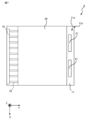
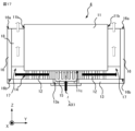
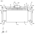
- FIG. 1 is a front view of an electronic device according to a first embodiment; 1 is a top view of an electronic device according to a first embodiment; 3 is a cross-sectional view of the electronic device according to the first embodiment taken along line III-III in FIG.
- FIG. 1 is a diagram showing an air flow in an electronic device according to a first embodiment;
- FIG. 1 is a diagram showing an air flow in an electronic device according to a first embodiment;
- FIG. 13 is a front view of an electronic device according to a second embodiment.
- 1 is a top view of an electronic device according to a second embodiment.
- 8 is a cross-sectional view taken along line VIII-VIII in FIG. 6 of the electronic device according to the second embodiment;
- FIG. 13 is a diagram showing an air flow in an electronic device according to a second embodiment.
- FIG. 13 is a diagram showing an air flow in an electronic device according to a second embodiment.
- FIG. 13 is a front view of an electronic device according to a third embodiment.
- 11 is a top view of an electronic device according to a third embodiment. 13 is a cross-sectional view of the electronic device according to the third embodiment taken along line XIII-XIII in FIG.
- FIG. 13 is a diagram showing an air flow in an electronic device according to a third embodiment.
- FIG. 13 is a diagram showing an air flow in an electronic device according to a third embodiment.
- FIG. 11 is a front view of a first modified example of the electronic device according to the embodiment; FIG.
- FIG. 13 is a diagram showing an air flow in a first modified example of the electronic device according to the embodiment;
- FIG. 11 is a front view of a second modified example of the electronic device according to the embodiment;
- FIG. 13 is a diagram showing an air flow in a second modified example of the electronic device according to the embodiment;
- FIG. 13 is a diagram illustrating a top surface of a housing of a third modified example of the electronic device according to the embodiment.
- FIG. 13 is a front view of a fourth modified example of the electronic device according to the embodiment;
- FIG. 13 is a diagram illustrating a top surface of a housing of a fourth modified example of the electronic device according to the embodiment;
- FIG. 13 is a diagram illustrating a top surface of a housing of a fifth modified example of the electronic device according to the embodiment;
- FIG. 13 is a front view of a sixth modified example of the electronic device according to the embodiment;
- the housing 11 has mounting surface 11a and bottom surface 11c, which are surfaces that intersect with the Z axis, and side surface 11b, which is a surface along the Z axis. Side surface 11b of housing 11 is positioned parallel to the XZ plane or the YZ plane.
- the mounting surface 11a is the top surface of the housing 11 that intersects with the Z axis, specifically, the outer surface of housing 11 that faces in the positive direction of the Z axis.
- the bottom surface 11c is the outer surface of housing 11 that intersects with the Z axis, which faces in the negative direction of the Z axis.
- Electronic components are attached to the surface opposite mounting surface 11a, i.e., the vertical upper part of the inner surface of housing 11.
- At least a portion of the first heat dissipation member 12 is located in the first gap 14.
- multiple first heat dissipation members 12 are located in the first gap 14, spaced apart from each other.
- the blower 15 When the blower 15 operates, as shown by the black arrow in FIG. 4, the blower 15 draws in air located vertically above the first air guide member 13 in the negative direction of the Z axis. As shown in FIG. 5, the blower 15 discharges the drawn air in the radial direction. By providing the first air guide member 13, the air discharged by the blower 15 flows between the first heat dissipation member 12 along the mounting surface 11a in the first gap 14 sandwiched between the first air guide member 13 and the mounting surface 11a of the housing 11, and flows out to the outside of the electronic device 1.
- the second air guide member 16 is provided at a position where the vertical lower end 16b is located vertically above the bottom surface 11c of the housing 11.
- the second air guide member 16 allows external air to flow into the second gap 17 from a gap below in the vertical direction, specifically, from the gap between the vertical lower end 16b of the second air guide member 16 and the installation surface of the electronic device 1. Therefore, as shown by the white arrow, the external air flows into the second gap 17 and moves vertically upward as described above.
- the operation of the blower 15 promotes natural convection in the second gap 17 as described above. As a result, the heat generated by the electronic components housed inside the housing 11 is transferred to the air flowing through the second gap 17 via the side surface 11b of the housing 11. This cools the electronic components.
- the electronic device 1 includes the first air guide member 13 and the second air guide member 16, and therefore, when the blower 15 is operated, air flows along the mounting surface 11a and air flows along the side surface 11b. As a result, more air flows along the housing 11, and the electronic device 1 has high cooling performance for the electronic components housed inside the housing 11.
- the electronic device 2 shown in Figures 6, 7, and Figure 8, which is a cross-sectional view taken along line VIII-VIII in Figure 6, comprises a plurality of first heat dissipation members 19 each having a fin shape whose main surface is parallel to the YZ plane, a first air guide member 20 that forms a first gap 14 between the mounting surface 11a, a blower 21 that is provided adjacent to one end of the mounting surface 11a and blows air toward the other end of the mounting surface 11a, and a plurality of second heat dissipation members 22 that are provided in the second gap 17.
- the multiple first heat dissipation members 19 are attached to the mounting surface 11a at positions spaced apart from each other. As shown in FIG. 8, in which the illustration of the first air guide member 20 is omitted from FIGS. 6 and 7, the first heat dissipation members 19 have a fin shape extending in the air blowing direction of the blower 21. In the second embodiment, the multiple first heat dissipation members 19 are arranged at intervals in the X-axis direction.
- the first heat dissipation members 19 are formed from a material with high thermal conductivity, for example, a metal material such as iron or aluminum, fine ceramics, graphite, etc.
- the first heat dissipation member 19 is attached to the mounting surface 11a by a mounting method such as welding or soldering.
- the first heat dissipation member 19 dissipates heat transferred from the electronic components housed inside the housing 11 through the mounting surface 11a of the housing 11 to the surrounding air.
- the first air guide member 20 is arranged with its main surface facing the mounting surface 11a, and forms a first gap 14 between itself and the mounting surface 11a.
- One end of the first air guide member 20 in the Y-axis direction is located adjacent to the blower 21.
- the other end of the first air guide member 20 in the Y-axis direction faces the second gap 17.
- the end of the first air guide member 20 on the negative Y-axis direction side is located vertically above the second gap 17.
- the first air guide member 20 is a flat plate-like member.
- the first air guide member 20 is attached to at least one of the multiple first heat dissipation members 19.
- the first air guide member 20 is attached to the first heat dissipation member 19 that serves as a support member among the multiple first heat dissipation members 19.
- the first air guide member 20 is attached to the first heat dissipation member 19 by an attachment method such as adhesion with an adhesive, fitting, fastening with a fastening member, welding, etc.
- At least a portion of the first heat dissipation member 19 is located in the first gap 14.
- multiple first heat dissipation members 19 are located in the first gap 14, spaced apart from each other.
- the blower 21 is an axial blower that is provided adjacent to one end of the mounting surface 11a in the Y-axis direction and blows air toward the other end of the mounting surface 11a in the Y-axis direction.
- the two blowers 21 provided in the electronic device 2 are provided with a gap in the X-axis direction.
- Each blower 21 is provided at the end of the mounting surface 11a on the positive Y-axis side and blows air in the negative Y-axis direction.
- the multiple second heat dissipation members 22 are located in the second gap 17 and attached to the side surface 11b.
- the second heat dissipation members 22 are located in the second gap 17 and arranged in the X-axis direction.
- the second heat dissipation members 22 have a fin shape extending in the vertical direction.
- the second heat dissipation members 22 are formed from a material with high thermal conductivity, for example, a metal material such as iron or aluminum, fine ceramics, graphite, etc.
- the second heat dissipation member 22 is attached to the side surface 11b by a mounting method such as welding or soldering.
- the second heat dissipation member 22 dissipates heat transferred from the electronic components housed inside the housing 11 through the side surface 11b of the housing 11 to the surrounding air.
- the second air guide member 16 is a flat plate-shaped member.
- the second air guide member 16 is attached to at least one of the multiple second heat dissipation members 22.
- the second air guide member 16 is attached to a second heat dissipation member 22 that serves as a support member among the multiple second heat dissipation members 22.
- the second air guide member 16 is attached to at least some of the second heat dissipation members 22 by an attachment method such as bonding with an adhesive, fitting, fastening with a fastening member, welding, etc.
- the blower 21 When the blower 21 operates, as shown by the black arrows in Figures 9 and 10, the blower 21 blows air in the negative direction of the Y axis.
- the air discharged by the blower 21 flows between the first heat dissipation member 19 along the mounting surface 11a in the first gap 14 sandwiched between the first air guide member 20 and the mounting surface 11a of the housing 11, and flows out to the outside of the electronic device 2.
- the heat generated by the electronic components housed inside the housing 11 is transferred to the air flowing between the first heat dissipation member 19 in the first gap 14 via the mounting surface 11a and the first heat dissipation member 19 of the housing 11. This cools the electronic components.
- air flow is generated as indicated by black arrows, and the air pressure becomes negative at the end of the first gap 14 located vertically above the second gap 17.
- air moves vertically upward in the second gap 17 formed between the second air guide member 16 and the side surface 11b.
- the second air guide member 16 is provided at a position where the vertical upper end 16a is away from the first air guide member 20, so air moving vertically upward along the side surface 11b of the housing 11 is allowed to flow between the vertical upper end 16a and the first air guide member 20. Therefore, as indicated by white arrows, air moving vertically upward in the second gap 17 moves along the first air guide member 20, passes between the vertical upper end 16a of the second air guide member 16 and the first air guide member 20, and flows out to the outside of the electronic device 2.
- the second air guide member 16 is provided at a position where the vertical lower end 16b is located vertically above the bottom surface 11c of the housing 11.
- the second air guide member 16 allows external air to flow into the second gap 17 from a gap below in the vertical direction, specifically, from the gap between the vertical lower end 16b of the second air guide member 16 and the installation surface of the electronic device 2. Therefore, as shown by the white arrow, the external air flows into the second gap 17 and moves vertically upward as described above.
- the operation of the blower 21 promotes natural convection in the second gap 17 as described above. As a result, the heat generated by the electronic components housed inside the housing 11 is transferred to the air flowing through the second gap 17 via the side surface 11b of the housing 11. This cools the electronic components.
- the electronic device 2 includes the first air guide member 20 and the second air guide member 16, and when the blower 21 is operated, air flows along the mounting surface 11a and air flows along the side surface 11b. As a result, more air flows along the housing 11, and the electronic device 2 has high cooling performance for the electronic components housed inside the housing 11.
- the electronic device 2 includes the second heat dissipation member 22 located in the second gap 17, heat is efficiently transferred from the electronic components housed inside the housing 11 to the air located in the second gap 17 via the side surface 11b and the second heat dissipation member 22. As a result, an electronic device 2 having high cooling performance for the electronic components housed inside the housing 11 is obtained.
- the configuration of the electronic device is not limited to the above example, and may be any configuration that allows air to flow along the mounting surface 11a and the side surface 11b to cool the electronic components housed inside the housing 11.
- An electronic device 3 having a different configuration from the electronic device 1 according to the first embodiment will be described in the third embodiment, focusing on the differences from the first embodiment.
- the electronic device 3 shown in Figures 11, 12, and 13, which is a cross-sectional view taken along line XIII-XIII in Figure 11, comprises a second air guide member 23 that forms a second gap 24 between itself and the side surface 11b, a first support member 25 that supports the first air guide member 13, and a second support member 26 that supports the second air guide member 23.
- the first air guide member 13 is supported by four first support members 25.
- the first air guide member 13 is attached to the four first support members 25 by an attachment method such as bonding with an adhesive, fitting, fastening with a fastening member, welding, etc.
- a portion of the second air guide member 23 is provided facing the side surface 11b, forming a second gap 24 between the side surface 11b.
- the second air guide member 23 has a portion facing the side surface 11b and a portion facing the ground surface of the electronic device 3.
- the second air guide member 23 is formed by bending a flat plate-shaped member at a right angle.
- the electronic device 3 includes a second air guide member 23, a portion of which faces the side surface 11b in the negative direction of the Y axis, and a second air guide member 23, a portion of which faces the side surface 11b in the positive direction of the Y axis.
- the second air guide member 23 is provided in a position where the vertical upper end 23a is separated from the first air guide member 13.
- the second air guide member 23 is provided in a position where the vertical lower end 23b is located vertically above the bottom surface 11c of the housing 11.
- each second air guide member 23 is supported by four second support members 26.
- the second air guide members 23 are attached to the four second support members 26 by an attachment method such as bonding with an adhesive, fitting, fastening with a fastening member, welding, etc.
- the first support member 25 and the second support member 26 are fixed to the ground surface of the electronic device 3.
- the blower 15 When the blower 15 operates, as shown by the black arrow in FIG. 14, the blower 15 draws in air located vertically above the first air guide member 13 in the negative direction of the Z axis. As shown in FIG. 15, the blower 15 discharges the drawn air in the radial direction.
- the air discharged by the blower 15 flows between the first heat dissipation member 12 along the mounting surface 11a in the first gap 14 sandwiched between the first air guide member 13 and the mounting surface 11a of the housing 11, and flows out to the outside of the electronic device 3.
- the heat generated by the electronic components housed inside the housing 11 is transferred to the air flowing between the first heat dissipation member 12 in the first gap 14 via the mounting surface 11a of the housing 11 and the first heat dissipation member 12. This cools the electronic components.
- the air flow indicated by the black arrows is generated, and the air pressure becomes negative at the end of the first gap 14 located vertically above the second gap 24.
- air moves vertically upward in the second gap 24 formed between the second air guide member 23 and the side surface 11b.
- the second air guide member 23 is provided at a position where the vertical upper end 23a is away from the first air guide member 13, so that the air that moves vertically upward along the side surface 11b of the housing 11 is allowed to flow between the vertical upper end 23a and the first air guide member 13.
- the air that moves vertically upward in the second gap 24 moves along the first air guide member 13, passes between the vertical upper end 23a of the second air guide member 23 and the first air guide member 13, and flows out to the outside of the electronic device 3.
- the second air guide member 23 is provided at a position where the vertical lower end 23b is located vertically above the bottom surface 11c of the housing 11.
- the second air guide member 23 allows external air to flow into the second gap 24 from a gap below the vertical direction, specifically, from the gap between the vertical lower end 23b of the second air guide member 23 and the installation surface of the electronic device 3. Therefore, as shown by the white arrow, the external air flows into the second gap 24 and moves vertically upward as described above.
- the operation of the blower 15 promotes natural convection in the second gap 24 as described above. As a result, the heat generated by the electronic components housed inside the housing 11 is transferred to the air flowing through the second gap 24 via the side surface 11b of the housing 11. This cools the electronic components.
- the electronic device 3 includes the first air guide member 13 and the second air guide member 23, and therefore, when the blower 15 is operated, air flows along the mounting surface 11a and air flows along the side surface 11b. As a result, more air flows along the housing 11, and the electronic device 3 has high cooling performance for the electronic components housed inside the housing 11.
- the electronic device 2 may include a second air guide member 16 or a second air guide member 23 corresponding to the side surface 11b facing the positive direction of the Y axis.
- the end of the first air guide member 20 in the Y axis direction may be located vertically above the second air guide member 23.
- the vertical upper end 16a of the second air guide member 16 or the vertical upper end 23a of the second air guide member 23 may abut against the first air guide member 20.
- the electronic device 3 may include the first heat dissipation member 19, the first air guide member 20, and the blower 21 that are included in the electronic device 2.
- the first air guide member 20 may be supported by the first support member 25.
- the mounting surface is not limited to the top surface of the housing 11 in the vertical direction.
- the bottom surface of the housing 11 in the vertical direction may be the mounting surface.
- the bottom surface 11c of the housing 11 provided in the electronic device 4 shown in FIG. 16 serves as a mounting surface to which the multiple first heat dissipation members 12 are attached.
- the configuration of the electronic device 4 is the same as the configuration of the electronic device 1.
- the second air guide member 16 is provided at a position where its vertical lower end 16b is adjacent to the first air guide member 13, and guides the air flowing through the first gap 14 to the second gap 17.
- the vertical lower end 16b of the second air guide member 16 is adjacent to the first air guide member 13 to an extent that it is possible to prevent the air discharged from the blower 15 and passing between the first heat dissipation member 12 from flowing out horizontally. It is preferable that the vertical lower end 16b of the second air guide member 16 abuts against the first air guide member 13.
- the blower 15 When the blower 15 operates, as shown by the black arrow in FIG. 17, the blower 15 draws in air located vertically below the first air guide member 13 in the positive direction of the Z axis. The blower 15 discharges the drawn-in air in the radial direction.
- the air discharged by the blower 15 flows between the first heat dissipation member 12 along the mounting surface 11a in the first gap 14 sandwiched between the first air guide member 13 and the mounting surface 11a of the housing 11.
- the second air guide member 16 By providing the second air guide member 16 at a position where the vertical lower end 16b is adjacent to the first air guide member 13, the air that passes between the first heat dissipation member 12 is guided to the second gap 17 and moves vertically upward through the second gap 17.
- the air that moves vertically upward through the second gap 17 flows out to the outside of the electronic device 4. Due to the above-mentioned air flow, heat is transferred from the electronic components housed inside the housing 11 to the air flowing through the first gap 14 and the second gap 17 via the bottom surface 11c and side surface 11b of the housing 11, and the electronic components are cooled. In the examples of Figures 16 and 17, it is preferable that the electronic components are located inside the housing 11 near the bottom surface 11c.
- the electronic device 4 may be provided with an axial blower that blows air in the negative direction of the Z axis.
- the air flows in the opposite direction to the air flow shown in FIG. 17. That is, the second air guide member 16 guides the air flowing through the second gap 17 to the first gap 14.
- the air flow transfers heat from the electronic components housed inside the housing 11 to the air flowing through the first gap 14 and the second gap 17 via the bottom surface 11c and side surface 11b of the housing 11, thereby cooling the electronic components.
- the blowing direction of the blower is not limited to the above example.
- the electronic device 5 shown in FIG. 18 is equipped with a blower 27, which is an axial blower that blows air in the positive direction of the Z axis.
- the blower 27 is attached to the first air guide member 13 with a portion of the blower 27 positioned in the ventilation hole 13a of the first air guide member 13.
- the second air guide member 16 is provided at a position where its vertical upper end 16a is adjacent to the first air guide member 13, and guides the air flowing through the second gap 17 to the first gap 14.
- the vertical upper end 16a of the second air guide member 16 is adjacent to the first air guide member 13 to an extent that air that has been sucked in by the blower 27, which blows air in the positive direction of the Z axis, and moved vertically upward through the second gap 17 can be prevented from flowing out horizontally. It is preferable that the vertical upper end 16a of the second air guide member 16 abuts the first air guide member 13.
- the blower 27 When the blower 27 operates, as shown by the black arrow in FIG. 19, the blower 27 sucks in air in the first gap 14, blows the sucked air in the positive direction of the Z axis, and discharges it from the ventilation hole 13a of the first air guide member 13. As a result, in the first gap 14, the air flows through the first heat dissipation member 12 toward the blower 27.
- the air sucked into the blower 27 flows between the first heat dissipation member 12 along the mounting surface 11a in the first gap 14 sandwiched between the first air guide member 13 and the mounting surface 11a of the housing 11.
- the air pressure becomes negative in the first gap 14 located vertically above the second gap 17.
- the air is phased vertically upward in the second gap 17 as shown by the white arrow.
- the second air guide member 16 is provided at a position where its vertical upper end 16a abuts the first air guide member 13. As a result, the second air guide member 16 guides the air that has moved vertically upward through the second gap 17 to the first gap 14.
- the air guided to the first gap 14 passes between the first heat dissipation members 12 in the first gap 14 and heads toward the blower 27. Due to the above-mentioned air flow, heat is transferred from the electronic components housed inside the housing 11 to the air flowing through the first gap 14 and second gap 17 via the mounting surface 11a and side surface 11b of the housing 11, thereby cooling the electronic components.
- electronic device 2 may include blower 21, which is an axial flow fan located at the end on the positive side of the Y axis and blows air in the negative direction of the Y axis, and blower 21, which is an axial flow fan located at the end on the negative side of the Y axis and blows air in the positive direction of the Y axis.
- blower 21 which is an axial flow fan located at the end on the positive side of the Y axis and blows air in the negative direction of the Y axis
- blower 21 which is an axial flow fan located at the end on the negative side of the Y axis and blows air in the positive direction of the Y axis.
- the number of second air guide members 16 is not limited to the above example.
- the electronic device 6 shown in FIG. 20 has four second air guide members 16 corresponding to the four side surfaces 11b. Each second air guide member 16 forms a second gap 17 between itself and the corresponding side surface 11b. By providing the second air guide members 16 facing each side surface 11b, an air flow is generated along each side surface 11b. As a result, the electronic components inside the housing 11 are further cooled.
- the electronic device 7 shown in Figures 21 and 22 includes multiple second heat dissipation members 22 arranged vertically and horizontally and having a fin shape.
- the electronic device 8 shown in FIG. 23 includes a plurality of first heat dissipation members 19 arranged in the air blowing direction of the blower 21 and in a direction perpendicular to the air blowing direction of the blower 21.
- first heat dissipation member 12, 19 may have a curved surface.
- second heat dissipation member 22 may have a curved surface.
- first heat dissipation members 12, 19 may be formed integrally with the housing 11.
- second heat dissipation member 22 may be formed integrally with the housing 11.
- the electronic device 9 shown in FIG. 24 includes a plurality of first heat dissipation members 28 that are heat pipes.
- the first heat dissipation members 28 include a main pipe 28a that extends in the Y-axis direction and is attached to the mounting surface 11a, and a branch pipe 28b that is connected to the main pipe 28a and extends in the vertical direction.
- the electronic device 9 further includes a plurality of heat dissipation fins 29 that are attached to the first heat dissipation members 28.
- the heat dissipation fin 29 located at the lower end in the vertical direction serves as a first air guide member.
- first support member 25 and the second support member 26 are not limited to the above examples.
- first support member 25 and the second support member 26 may have a plate-like shape.
- the electronic device 1-9 is not limited to being mounted on an aircraft, but can be mounted on any moving object.
- the electronic device 1-9 can also be installed at any location on ground facilities.
- the electronic device 1 can be mounted under the floor of a railway vehicle. In this case, if there is space vertically below the electronic device 1, the vertical lower end 16b of the second air guide member 16 can be positioned vertically below the bottom surface 11c of the housing 11.
Landscapes
- Cooling Or The Like Of Electrical Apparatus (AREA)
Priority Applications (2)
| Application Number | Priority Date | Filing Date | Title |
|---|---|---|---|
| JP2025542269A JP7829817B2 (ja) | 2023-08-25 | 2023-08-25 | 電子機器 |
| PCT/JP2023/030764 WO2025046663A1 (ja) | 2023-08-25 | 2023-08-25 | 電子機器 |
Applications Claiming Priority (1)
| Application Number | Priority Date | Filing Date | Title |
|---|---|---|---|
| PCT/JP2023/030764 WO2025046663A1 (ja) | 2023-08-25 | 2023-08-25 | 電子機器 |
Publications (1)
| Publication Number | Publication Date |
|---|---|
| WO2025046663A1 true WO2025046663A1 (ja) | 2025-03-06 |
Family
ID=94818366
Family Applications (1)
| Application Number | Title | Priority Date | Filing Date |
|---|---|---|---|
| PCT/JP2023/030764 Pending WO2025046663A1 (ja) | 2023-08-25 | 2023-08-25 | 電子機器 |
Country Status (2)
| Country | Link |
|---|---|
| JP (1) | JP7829817B2 (https=) |
| WO (1) | WO2025046663A1 (https=) |
Citations (3)
| Publication number | Priority date | Publication date | Assignee | Title |
|---|---|---|---|---|
| JP2005110428A (ja) * | 2003-09-30 | 2005-04-21 | Toshiba Elevator Co Ltd | 電力変換素子冷却装置 |
| JP2009231701A (ja) * | 2008-03-25 | 2009-10-08 | Fujikura Ltd | 電子機器用冷却装置 |
| WO2019111755A1 (ja) * | 2017-12-07 | 2019-06-13 | 三菱電機株式会社 | 半導体装置 |
Family Cites Families (4)
| Publication number | Priority date | Publication date | Assignee | Title |
|---|---|---|---|---|
| JPH062315Y2 (ja) * | 1986-01-23 | 1994-01-19 | 富士電機株式会社 | インバ−タ装置 |
| US7418995B2 (en) * | 2004-01-14 | 2008-09-02 | Vanner, Inc. | System for cooling environmentally sealed enclosures |
| JP5747633B2 (ja) * | 2010-08-02 | 2015-07-15 | 富士電機株式会社 | 電子機器 |
| JP7211107B2 (ja) * | 2019-01-25 | 2023-01-24 | 株式会社Jvcケンウッド | 排熱構造および電子機器 |
-
2023
- 2023-08-25 JP JP2025542269A patent/JP7829817B2/ja active Active
- 2023-08-25 WO PCT/JP2023/030764 patent/WO2025046663A1/ja active Pending
Patent Citations (3)
| Publication number | Priority date | Publication date | Assignee | Title |
|---|---|---|---|---|
| JP2005110428A (ja) * | 2003-09-30 | 2005-04-21 | Toshiba Elevator Co Ltd | 電力変換素子冷却装置 |
| JP2009231701A (ja) * | 2008-03-25 | 2009-10-08 | Fujikura Ltd | 電子機器用冷却装置 |
| WO2019111755A1 (ja) * | 2017-12-07 | 2019-06-13 | 三菱電機株式会社 | 半導体装置 |
Also Published As
| Publication number | Publication date |
|---|---|
| JP7829817B2 (ja) | 2026-03-13 |
| JPWO2025046663A1 (https=) | 2025-03-06 |
Similar Documents
| Publication | Publication Date | Title |
|---|---|---|
| US10082850B2 (en) | Electronic device | |
| CN105932538A (zh) | 具备具有散热翅片的l字状热传导部件的空冷式激光装置 | |
| EP3349555A1 (en) | Electronic apparatus | |
| KR102513609B1 (ko) | 전력전자기기의 하부 모듈 | |
| JP2018160659A (ja) | 冷却構造体、冷却システム、発熱装置および構造物 | |
| KR20230116917A (ko) | 광조사 장치 | |
| CN221930483U (zh) | 电子设备 | |
| WO2018173942A1 (ja) | 冷却構造体、冷却システム、発熱装置および構造物 | |
| WO2025046663A1 (ja) | 電子機器 | |
| JP2001260877A (ja) | 鉄道車両用電力変換装置 | |
| CN112243334A (zh) | 发热部件的散热结构 | |
| JP6837565B2 (ja) | 鉄道車両の電力変換装置および電力変換装置を搭載した鉄道車両 | |
| US12588170B2 (en) | In-vehicle device including cooling apparatus | |
| US11540427B2 (en) | Converter having a separate interior | |
| USRE40369E1 (en) | Heat sink and electronic device employing the same | |
| WO2022018851A1 (ja) | 電子機器 | |
| JP2002368473A (ja) | 発熱性電子部品放熱装置、放熱構造を有する電子機器および電子装置 | |
| JP2006003928A (ja) | パソコンの冷却装置 | |
| KR101996616B1 (ko) | 방열 장치를 구비하는 전자기기 | |
| EP3671023A1 (en) | Heat exchanger for electronic components | |
| JP7738811B2 (ja) | コイル装置および車載機器 | |
| US11956926B2 (en) | Outdoor unit | |
| JP4286081B2 (ja) | 画像形成装置 | |
| WO2025220059A1 (ja) | 冷却装置および電子機器 | |
| JP2024049547A (ja) | 電子機器 |
Legal Events
| Date | Code | Title | Description |
|---|---|---|---|
| 121 | Ep: the epo has been informed by wipo that ep was designated in this application |
Ref document number: 23950617 Country of ref document: EP Kind code of ref document: A1 |
|
| ENP | Entry into the national phase |
Ref document number: 2025542269 Country of ref document: JP Kind code of ref document: A |
|
| WWE | Wipo information: entry into national phase |
Ref document number: 2025542269 Country of ref document: JP |
|
| WWE | Wipo information: entry into national phase |
Ref document number: 202517118256 Country of ref document: IN |
|
| WWP | Wipo information: published in national office |
Ref document number: 202517118256 Country of ref document: IN |