WO2025041299A1 - 空気調和装置および異常検出方法 - Google Patents
空気調和装置および異常検出方法 Download PDFInfo
- Publication number
- WO2025041299A1 WO2025041299A1 PCT/JP2023/030308 JP2023030308W WO2025041299A1 WO 2025041299 A1 WO2025041299 A1 WO 2025041299A1 JP 2023030308 W JP2023030308 W JP 2023030308W WO 2025041299 A1 WO2025041299 A1 WO 2025041299A1
- Authority
- WO
- WIPO (PCT)
- Prior art keywords
- refrigerant
- voltage
- control unit
- abnormality
- refrigerant circuit
- Prior art date
- Legal status (The legal status is an assumption and is not a legal conclusion. Google has not performed a legal analysis and makes no representation as to the accuracy of the status listed.)
- Pending
Links
Images


Classifications
-
- F—MECHANICAL ENGINEERING; LIGHTING; HEATING; WEAPONS; BLASTING
- F24—HEATING; RANGES; VENTILATING
- F24F—AIR-CONDITIONING; AIR-HUMIDIFICATION; VENTILATION; USE OF AIR CURRENTS FOR SCREENING
- F24F11/00—Control or safety arrangements
- F24F11/30—Control or safety arrangements for purposes related to the operation of the system, e.g. for safety or monitoring
- F24F11/32—Responding to malfunctions or emergencies
- F24F11/36—Responding to malfunctions or emergencies to leakage of heat-exchange fluid
-
- F—MECHANICAL ENGINEERING; LIGHTING; HEATING; WEAPONS; BLASTING
- F24—HEATING; RANGES; VENTILATING
- F24F—AIR-CONDITIONING; AIR-HUMIDIFICATION; VENTILATION; USE OF AIR CURRENTS FOR SCREENING
- F24F11/00—Control or safety arrangements
- F24F11/30—Control or safety arrangements for purposes related to the operation of the system, e.g. for safety or monitoring
- F24F11/32—Responding to malfunctions or emergencies
- F24F11/38—Failure diagnosis
-
- F—MECHANICAL ENGINEERING; LIGHTING; HEATING; WEAPONS; BLASTING
- F25—REFRIGERATION OR COOLING; COMBINED HEATING AND REFRIGERATION SYSTEMS; HEAT PUMP SYSTEMS; MANUFACTURE OR STORAGE OF ICE; LIQUEFACTION SOLIDIFICATION OF GASES
- F25B—REFRIGERATION MACHINES, PLANTS OR SYSTEMS; COMBINED HEATING AND REFRIGERATION SYSTEMS; HEAT PUMP SYSTEMS
- F25B49/00—Arrangement or mounting of control or safety devices
- F25B49/02—Arrangement or mounting of control or safety devices for compression type machines, plants or systems
Definitions
- This disclosure relates to an air conditioning device equipped with a refrigerant circuit and an abnormality detection method.
- Patent Document 1 discloses a technology in which a refrigerant leak detection device detects refrigerant leaks based on the power value obtained from the three-phase driving current supplied from an inverter circuit to a brushless DC (Direct Current) motor.
- a refrigerant leak detection device detects refrigerant leaks based on the power value obtained from the three-phase driving current supplied from an inverter circuit to a brushless DC (Direct Current) motor.
- the present disclosure has been made in consideration of the above, and aims to provide an air conditioning device that is simple in configuration and capable of detecting abnormalities caused by different factors.
- the air conditioning apparatus includes a refrigerant circuit in which a refrigerant is compressed by a compressor driven by a compressor motor, a power converter that converts a first AC voltage supplied from an AC power source into a second AC voltage for driving the compressor motor and outputs the second AC voltage to the compressor motor and detects the current of the second AC voltage output to the compressor motor, and a control unit that generates a drive signal for generating the second AC voltage in the power converter and outputs the drive signal to the power converter, and detects refrigerant leakage from the refrigerant circuit and compressor abnormalities using the current detection value of the current of the second AC voltage detected by the power converter.
- the air conditioning device has a simple configuration, while being able to detect abnormalities caused by different factors.
- FIG. 1 is a diagram showing a configuration example of an air conditioning device according to a first embodiment.
- FIG. 2 is a diagram showing a configuration example of a power converter included in the air conditioning apparatus according to the first embodiment;
- FIG. 2 is a diagram showing a configuration example of a control unit included in the air conditioning apparatus according to the first embodiment;
- FIG. 1 is a diagram showing an example of a hardware configuration for implementing a control unit provided in an air conditioning apparatus according to a first embodiment.
- FIG. 1 is a first diagram showing an example of the configuration of a control unit provided in an air conditioning apparatus according to a second embodiment;
- FIG. 2 is a second diagram showing an example of the configuration of a control unit provided in an air conditioning apparatus according to embodiment 2.
- FIG. 13 is a diagram showing a configuration example of an air conditioning device according to a third embodiment.
- FIG. 13 is a diagram showing a configuration example of an air conditioning device according to a fourth embodiment.
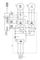
- Fig. 1 is a diagram showing an example of the configuration of an air conditioning device 200 according to embodiment 1.
- the air conditioning device 200 is connected to an AC power source 1, driven by an AC voltage supplied from the AC power source 1, and performs air conditioning control of a space that is an air conditioning control target (not shown).
- Fig. 1 shows an example in which the AC power source 1 is a three-phase power source, but the present invention is not limited to this, and the AC power source 1 may also be a single-phase power source.
- the air conditioning device 200 includes a power converter 2, a compressor 3, a control unit 4, a fan 5, a fan motor 50, and a refrigerant circuit 100.
- the compressor 3 includes a compressor motor 30 and a compression element 31.
- the refrigerant circuit 100 includes a four-way valve 111, a heat source side heat exchanger 112, on-off valves 113a, 113b, an expansion device 121, and a load side heat exchanger 122.
- the refrigerant circuit 100 also includes a compression element 31 included in the compressor 3. As shown in FIG.
- the power converter 2, the compressor 3, the control unit 4, the fan 5, the fan motor 50, and the four-way valve 111, the heat source side heat exchanger 112, and the on-off valves 113a, 113b included in the refrigerant circuit 100 are installed in the outdoor unit 110.
- the expansion device 121 and the load side heat exchanger 122 of the refrigerant circuit 100 are installed in the indoor unit 120.
- the on-off valves 113a and 113b are valves for controlling the flow of refrigerant in the refrigerant circuit 100, and are controlled to open and close by a refrigerant circuit control signal from the control unit 4.
- the control unit 4 can control the flow of refrigerant in the refrigerant circuit 100 by the refrigerant circuit control signal.
- the compressor 3 compresses the refrigerant flowing in the refrigerant circuit 100 to create a refrigeration cycle. That is, in the refrigerant circuit 100, the refrigerant is compressed by the compressor 3, which is driven by the compressor motor 30.
- the power converter 2 converts the first AC voltage supplied from the AC power source 1 into a second AC voltage for driving the compressor motor 30 provided in the compressor 3, and outputs the second AC voltage to the compressor motor 30.
- the power converter 2 also converts the first AC voltage supplied from the AC power source 1 into a third AC voltage for driving the fan motor 50, which is the driving source of the fan 5 and rotates the fan 5, and outputs the third AC voltage to the fan motor 50.
- the power converter 2 also detects the bus voltage, which is the voltage across the main circuit capacitor described later, and detects the motor current of the second AC voltage output from the inverter described later to the compressor motor 30.
- the power converter 2 outputs the detected voltage detection value of the bus voltage and the detected current detection value of the motor current to the control unit 4.
- the control unit 4 acquires a voltage detection value of the bus voltage and a current detection value of the motor current from the power converter 2.
- the control unit 4 also acquires a command value for the air conditioning unit 200 from a user of the air conditioning unit 200 via a remote controller (not shown).
- the command value indicates, for example, an operating mode such as cooling or heating, a set temperature, and the like, but may include other information.
- the control unit 4 uses the acquired information to control the operation of the on-off valves 113a and 113b provided in the power converter 2 and the refrigerant circuit 100. Specifically, the control unit 4 generates a drive signal for generating a second AC voltage in the power converter 2 and outputs it to the power converter 2.
- the drive signal generated by the control unit 4 is for turning on and off the switching elements of the inverter provided in the power converter 2.
- the drive signal generated by the control unit 4 is generated by a general method, and therefore a detailed description is omitted.
- the control unit 4 detects refrigerant leakage from the refrigerant circuit 100 and abnormalities in the compressor 3 using the current detection value of the motor current of the second AC voltage detected by the power converter 2.
- the characteristic feature of this embodiment is the content of control by the control unit 4. Therefore, the configuration of the air conditioning device 200 shown in FIG. 1 is only an example, and the configuration of the air conditioning device 200 is not limited to the example in FIG. 1.
- FIG. 2 is a diagram showing an example of the configuration of the power converter 2 provided in the air conditioning device 200 according to the first embodiment.
- the power converter 2 includes a converter 22, a reactor 23, main circuit capacitors 24a and 24b, inverters 25a and 25b, a current detector 21, and voltage detectors 26a and 26b.
- the converter 22 rectifies the first AC voltage supplied from the AC power source 1.
- the converter 22 may have a boost function.
- FIG. 2 shows an example in which the power converter 2 has a common converter 22 for the inverters 25a and 25b, the power converter 2 can also be configured to have a converter 22 for each of the inverters 25a and 25b, i.e., in the example of FIG. 2, two converters 22 are provided.
- the reactor 23 is provided between the converter 22 and the main circuit capacitors 24a, 24b. Note that the installation position and the number of reactors 23 are not limited to the example in FIG. 2.
- the power converter 2 may have reactors 23 installed in each phase between the AC power source 1 and the converter 22.
- the power converter 2 may have reactors 23 installed in one of the two phases between the AC power source 1 and the converter 22.
- the main circuit capacitor 24a smoothes the voltage rectified by the converter 22 and supplies the smoothed voltage to the inverter 25a.
- the main circuit capacitor 24b smoothes the voltage rectified by the converter 22 and supplies the smoothed voltage to the inverter 25b.
- the power converter 2 is configured to have two main circuit capacitors 24a, 24b, but if the bus voltage is common, the power converter 2 can also be configured to have one main circuit capacitor 24a. In this case, the power converter 2 branches the output destination on the output side of the main circuit capacitor 24a, or to the right of the main circuit capacitor 24a in the example of FIG. 2, with one output destination being the inverter 25a and the other output destination being the inverter 25b.
- the inverter 25a converts the voltage smoothed by the main circuit capacitor 24a into a second AC voltage and outputs it to the compressor motor 30.
- the inverter 25a has three legs, each of which has two switching elements connected in series, although not shown in the figure.
- the inverter 25a turns each switching element on and off in accordance with a drive signal obtained from the control unit 4, thereby converting the voltage smoothed by the main circuit capacitor 24a into a three-phase second AC voltage and outputting the three-phase second AC voltage to the compressor motor 30.
- the inverter 25b converts the voltage smoothed by the main circuit capacitor 24b into a third AC voltage and outputs it to the fan motor 50.
- the inverter 25b has three legs, each of which has two switching elements connected in series, although not shown in the figure.
- the inverter 25b turns each switching element on and off according to the drive signal obtained from the control unit 4, converting the voltage smoothed by the main circuit capacitor 24b into a three-phase third AC voltage, and outputs the three-phase third AC voltage to the fan motor 50.
- the current detection unit 21 detects the motor current, which is the current of the second AC voltage output from the inverter 25a, i.e., the power converter 2, to the compressor motor 30.
- the current detection unit 21 outputs the detected current detection value of the motor current to the control unit 4.
- the current detection value of the motor current detected by the current detection unit 21 is a parameter required for the control calculation of the control unit 4 when generating a drive signal to the inverter 25a to drive the compressor motor 30.
- the current detection value of the motor current detected by the current detection unit 21 is also used for abnormality judgment by the abnormality judgment unit 40 provided in the control unit 4.
- the current detection unit 21 can be realized, for example, by providing an ACCT (Alternating Current Transformer), a DCCT (Direct Current Transformer), a shunt resistor, etc. in a specified phase among the phases connecting the inverter 25a and the compressor motor 30, or by providing a shunt resistor on the lower arm or bus of each phase of the inverter 25a, and using a well-known method of restoring the motor current from the detected current value.
- the current detection unit 21 may detect the current of a specified phase, and the control unit 4 may use a known method to restore the motor current from the detected current value.
- the voltage detection unit 26a detects the voltage across the main circuit capacitor 24a and outputs the detected voltage across the main circuit capacitor 24a to the control unit 4 as a bus voltage.
- the voltage detection unit 26b detects the voltage across the main circuit capacitor 24b and outputs the detected voltage across the main circuit capacitor 24b to the control unit 4 as a bus voltage.
- the abnormality determination unit 40 determines at least the leakage state of the refrigerant from the refrigerant circuit 100 and the abnormal state of the compressor motor 30 based on the current detection value of the motor current output from the power converter 2 to the compressor motor 30. These abnormal states can be determined based on the load state of the compressor motor 30, but in this embodiment, the abnormality determination unit 40 determines the abnormal state by using the current detection value of the motor current output from the power converter 2 to the compressor motor 30 detected by the current detection unit 21 to indirectly determine the load state.
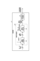
- FIG. 3 is a diagram showing an example of the configuration of the control unit 4 provided in the air conditioning device 200 according to the first embodiment.
- the control unit 4 includes an abnormality determination unit 40 and a control signal generation unit 45.
- the abnormality determination unit 40 includes a coordinate conversion unit 43 and an abnormality detection unit 44. As described above, the operation of generating drive signals for the inverters 25a and 25b in the control unit 4 may be a general operation, so a detailed description will be omitted. In the following, the operation of the abnormality determination unit 40 provided in the control unit 4 will be mainly described. In addition, in the control unit 4, the control signal generation unit 45 is assumed to generate drive signals for the inverters 25a and 25b through normal operation.
- the coordinate conversion unit 43 converts the motor current, which is the current detection value detected by the current detection unit 21, into the d-axis current Id and the q-axis current Iq, which are currents in the dq-axis coordinate system, using the phase ⁇ , which is the electrical angle obtained in the process of the well-known motor position sensorless control calculation process, which corresponds to the rotor position of the compressor motor 30.
- the q-axis current Iq corresponds to the motor torque current component, and since the current flows to balance with the motor load torque, fluctuations in the motor load caused by various factors appear in the q-axis current Iq.
- the abnormality detection unit 44 mainly uses this q-axis current Iq to detect abnormalities according to the principle described below.
- the abnormality detection unit 44 uses the motor rotation frequency of the compressor motor 30 together with the d-axis current Id and q-axis current Iq obtained from the coordinate conversion unit 43, as shown in FIG. 3.
- the motor rotation frequency of the compressor motor 30 is also a parameter used in general motor control, like the above-mentioned phase ⁇ , a detailed description will be omitted.
- the abnormality detection unit 44 uses the current value of the compressor motor 30, in particular the q-axis current Iq, as an index to determine whether or not there is a refrigerant leak.
- the abnormality detection unit 44 compares the q-axis current Iq obtained from the current detection value of the compressor motor 30 with a predefined threshold value, and determines whether or not the q-axis current Iq is smaller than the threshold value, thereby determining whether or not there is a refrigerant leak.
- the threshold value is set, for example, by a person in charge at the manufacturer of the air conditioning device 200, taking into account the operating state of the air conditioning device 200, and is stored in a memory (not shown) of the control unit 4.
- the abnormality detection unit 44 separately distinguishes between an abnormality caused by a refrigerant leak and an abnormality caused by wear of the compressor 3 by controlling as follows.
- the abnormality detection unit 44 can determine whether or not a refrigerant leak has occurred using the current value of the compressor motor 30, particularly the absolute value of the q-axis current Iq, as an index. Since a refrigerant leak is an irreversible abnormality, the abnormality detection unit 44 may determine that an abnormality has occurred when the value remains below a threshold value continuously, or when the rate of change per unit time is below a threshold value.
- the abnormality detection unit 44 can make the same determination using the absolute value of the current of the compressor motor 30 as when the absolute value of the q-axis current Iq is used.
- a load torque fluctuation occurs with one rotation of the compressor motor 30 being one cycle. Therefore, if a frequency analysis is performed on the q-axis current Iq while an abnormality is occurring in the compressor 3, the analysis result will have a motor rotation frequency component. If the compressor 3 is a twin rotary compressor, the analysis result will have a frequency component that is twice the motor rotation frequency. Furthermore, since frictional resistance increases when damage occurs to the sliding parts of the compressor 3, the analysis result will have a load torque fluctuation that is superimposed on the motor rotation frequency component caused by frictional resistance or an integer multiple of the motor rotation frequency component in addition to the load torque fluctuation.
- the abnormality detection unit 44 performs frequency analysis based on the well-known Fourier series expansion principle or FFT (Fast Fourier Transform) analysis to extract the load torque fluctuation of the motor rotation frequency component or the integer multiple component of the motor rotation frequency component caused by friction resistance, and extracts the motor rotation frequency component or the integer multiple component of the motor rotation frequency component contained in the q-axis current Iq. If the value of the extracted frequency component exceeds a predefined threshold, the abnormality detection unit 44 can determine that an abnormality has occurred in the sliding part of the compressor 3 that affects the torque fluctuation of the compressor 3.
- FFT Fast Fourier Transform
- the abnormality detection unit 44 may continuously record the intensity of the motor rotation frequency component or the integer multiple component of the motor rotation frequency component of the compressor 3, and determine that an abnormality has occurred when the intensity of the frequency component continuously exceeds the threshold or the increase rate per specified time exceeds the threshold.
- the thresholds for determining the above-mentioned abnormality may be set based on empirical values, or may be set based on the load of the compressor 3 theoretically determined from the pressure conditions of the refrigeration cycle, i.e., the motor current generated when the motor load of the compressor motor 30 is applied, or preferably the q-axis current Iq as an index.
- the load of the compressor 3 changes depending on the pressure conditions of the compressor 3, the motor rotation frequency, etc., and the range of values to be determined as a normal state also changes, so each threshold may be made variable depending on the pressure conditions of the compressor 3, the motor rotation frequency, etc.
- the processing load when making the threshold variable can be reduced while improving the detection accuracy of abnormalities.
- the q-axis current Iq increases in the air conditioning device 200, it may be due to factors other than an abnormality in the compressor 3.
- an increase in the q-axis current Iq in the air conditioning device 200 is likely to indicate some kind of abnormality, and is at the very least considered to be an abnormal state. Therefore, even if the abnormality detection unit 44 is unable to determine whether or not an abnormality has occurred in the compressor 3 despite the increase in the q-axis current Iq, it may notify the control signal generation unit 45 that an abnormality has occurred in the air conditioning device 200.
- the abnormality detection unit 44 of the abnormality judgment unit 40 can clearly separate the cause of the abnormality appearing in the current of the compressor motor 30 and accurately determine the type of abnormal state.
- the abnormality detection unit 44 can further perform detailed analysis for each frequency component by using FFT analysis. For example, when a small-capacity capacitor, such as a film capacitor, is used as the main circuit capacitor 24a, the fluctuation caused by the AC power source 1 is superimposed on the bus voltage, and the frequency component of the first AC voltage supplied from the AC power source 1 and the integer multiple component of the frequency of the first AC voltage are also superimposed on the q-axis current Iq.
- the integer multiple component is a double component when the AC power source 1 is a single-phase power source, and a six-fold component when the AC power source 1 is a three-phase power source.
- the abnormality detection unit 44 can process the components caused by the first AC voltage supplied from the AC power source 1 after separating or attenuating these frequency components by a well-known filtering process. As a result, the abnormality detection unit 44 can make a judgment after removing the effects of disturbances of the q-axis current Iq that occur due to causes other than those mentioned above, thereby improving the accuracy of the judgment.
- the abnormality detection unit 44 may perform the process of detecting refrigerant leakage from the refrigerant circuit 100 and the process of detecting an abnormality in the compressor 3 in parallel, or may perform them sequentially. When performing them sequentially, the abnormality detection unit 44 first performs the process of detecting refrigerant leakage from the refrigerant circuit 100, and then performs the process of detecting an abnormality in the compressor 3.
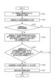
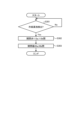
- Figure 4 is a flowchart showing the process of detecting refrigerant leakage from the refrigerant circuit 100 by the abnormality judgment unit 40 of the control unit 4 provided in the air conditioning apparatus 200 according to embodiment 1.
- the coordinate conversion unit 43 converts the motor current acquired from the current detection unit 21 into a d-axis current Id and a q-axis current Iq (step S101) and outputs them to the abnormality detection unit 44.
- the abnormality detection unit 44 compares the q-axis current Iq with a refrigerant leakage threshold for detecting refrigerant leakage from the refrigerant circuit 100 (step S102).
- step S103: Yes the abnormality detection unit 44 determines that refrigerant is not leaking from the refrigerant circuit 100 and ends the process. If the q-axis current Iq is less than the refrigerant leakage threshold (step S103: No), the abnormality detection unit 44 determines that there is a possibility of refrigerant leakage from the refrigerant circuit 100, and further checks whether the state in which the q-axis current Iq is less than the refrigerant leakage threshold continues for a specified first period or more, and compares the rate of change of the q-axis current Iq in the specified second period with the specified rate of change threshold (step S104).
- step S105 If the state in which the q-axis current Iq is less than the refrigerant leakage threshold has not continued for a specified first period or more, and the rate of change of the q-axis current Iq in the specified second period is greater than the specified rate of change threshold (step S105: No), the abnormality detection unit 44 determines that refrigerant is not leaking from the refrigerant circuit 100 and terminates the process.
- the abnormality detection unit 44 determines that refrigerant is leaking from the refrigerant circuit 100 (step S106). The abnormality detection unit 44 notifies the control signal generation unit 45 of the type of abnormal state, in this case, that an abnormality of refrigerant leakage from the refrigerant circuit 100 has occurred (step S107).
- the control signal generating unit 45 can generate a refrigerant circuit control signal for closing the on-off valves 113a and 113b of the refrigerant circuit 100 by acquiring the type of abnormal state indicating the occurrence of a refrigerant leakage abnormality from the abnormality detecting unit 44, and output the refrigerant circuit control signal to the refrigerant circuit 100.
- the control unit 4 detects a refrigerant leak from the refrigerant circuit 100, it generates a refrigerant circuit control signal for closing the on-off valves 113a and 113b and outputs the refrigerant circuit 100.
- the abnormality determining unit 40 periodically repeats the processing of the flowchart shown in FIG. 4.
- the control signal generating unit 45 may generate and output to the power converter 2 a drive signal for converting the first AC voltage to a third AC voltage and outputting the voltage to the fan motor 50, thereby rotating the fan 5 and diffusing the leaked refrigerant.
- the air conditioning device 200 can prevent the refrigerant from accumulating in the same place, thereby preventing the leaked refrigerant from igniting.
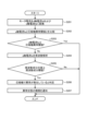
- step S201 is a flowchart showing the process of detecting an abnormality in the compressor 3 by the abnormality determination unit 40 of the control unit 4 provided in the air conditioning apparatus 200 according to embodiment 1.
- the coordinate conversion unit 43 converts the motor current acquired from the current detection unit 21 into a d-axis current Id and a q-axis current Iq (step S201), and outputs them to the abnormality detection unit 44.
- the process of step S201 is the same as the process of step S101 in the flowchart shown in FIG. 4.
- the abnormality detection unit 44 compares the q-axis current Iq with a compressor abnormality threshold for detecting an abnormality in the compressor 3 (step S202).
- step S203: Yes If the q-axis current Iq is equal to or lower than the compressor abnormality threshold (step S203: Yes), the abnormality detection unit 44 determines that no abnormality has occurred in the compressor 3 and ends the process. If the q-axis current Iq is greater than the compressor abnormality threshold (step S203: No), the abnormality detection unit 44 determines that an abnormality may have occurred in the compressor 3 and further performs frequency analysis on the q-axis current Iq (step S204).
- step S205: No the abnormality detection unit 44 determines that no abnormality has occurred in the compressor 3 and ends the process. If the value of the frequency component obtained by the frequency analysis is equal to or greater than the specified frequency component threshold (step S205: Yes), the abnormality detection unit 44 determines that an abnormality has occurred in the compressor 3 (step S206). The abnormality detection unit 44 notifies the control signal generation unit 45 of the type of abnormal state, in this case, that an abnormality has occurred in the compressor 3 (step S207).
- control signal generation unit 45 can stop generating a drive signal for the inverter 25a by acquiring the type of abnormal state indicating that an abnormality has occurred in the compressor 3 from the abnormality detection unit 44.
- the abnormality determination unit 40 periodically repeats the process of the flowchart shown in FIG. 5.
- FIG. 6 is a flowchart showing the process of detecting refrigerant leakage from the refrigerant circuit 100 and the process of detecting an abnormality in the compressor 3 by the abnormality determination unit 40 of the control unit 4 provided in the air conditioning device 200 according to the first embodiment.
- the process shown in steps S101 to S107 is the same as the process of steps S101 to S107 in the flowchart shown in FIG. 4, and the process shown in steps S202 to S207 is the same as the process of steps S202 to S207 in the flowchart shown in FIG. 5. Therefore, a detailed description of the flowchart shown in FIG. 6 is omitted.
- the abnormality determination unit 40 first performs the process of detecting refrigerant leakage from the refrigerant circuit 100, and then performs the process of detecting an abnormality in the compressor 3.
- FIG. 7 is a diagram showing an example of a hardware configuration that realizes the control unit 4 provided in the air conditioning device 200 according to the first embodiment.
- the control unit 4 is realized by a processor 910 and a memory 920.
- the processor 910 is a CPU (also called a central processing unit, processing unit, arithmetic unit, microprocessor, microcomputer, processor, or DSP (Digital Signal Processor)) or a system LSI (Large Scale Integration).
- Examples of the memory 920 include non-volatile or volatile semiconductor memories such as RAM (Random Access Memory), ROM (Read Only Memory), flash memory, EPROM (Erasable Programmable Read Only Memory), and EEPROM (registered trademark) (Electrically Erasable Programmable Read Only Memory). Furthermore, the memory 920 is not limited to these and may be a magnetic disk, optical disk, compact disk, mini disk, or DVD (Digital Versatile Disc).
- the abnormality determination unit 40 of the control unit 4 converts the motor current of the second AC voltage from the inverter 25a to the compressor motor 30 detected by the current detection unit 21 of the power converter 2 into a d-axis current Id and a q-axis current Iq, compares the q-axis current Iq with a threshold value for detecting refrigerant leakage from the refrigerant circuit 100, and compares the q-axis current Iq with a threshold value for detecting an abnormality in the compressor 3. This allows the abnormality determination unit 40 to detect an abnormality that has occurred in the air conditioning device 200 and determine the cause of the abnormality.
- the abnormality determination unit 40 can determine the cause of the abnormality by performing a conversion process to a dq-axis coordinate system used in general control and comparing the values obtained by the conversion process with each threshold value, the processing load can be reduced compared to the case of calculating the power value described in the background art.
- the air conditioning device 200 does not need to add special sensors to the configuration of a general air conditioning device, and can detect abnormalities due to different factors while having a simple configuration.
- the air conditioning device 200 can detect abnormalities caused by different factors, and can respond according to the cause of the abnormality.
- the refrigerant used in the refrigerant circuit 100 of the air conditioning device 200 may be, for example, a fluorine-based refrigerant with a low Global Warming Potential (GWP), or a hydrocarbon-based refrigerant, i.e., HC refrigerant.
- GWP Global Warming Potential
- the refrigerant include a single refrigerant selected from R1234yf, R1234ze, R32, and R290, or a mixture of two or more of these, or a mixture of any of these with another refrigerant.
- the refrigerant include a mixture of R1132(E), or a mixture of R1123.
- refrigerants include mixed refrigerants of R516A, R445A, R444A, R454C, R444B, R454A, R455A, R457A, R459B, R452B, R454B, R447B, R447A, R446A, and R459A.
- Embodiment 2 In the second embodiment, a case will be described in which the air conditioning apparatus is provided with a storage unit.
- FIG. 8 is a first diagram showing an example configuration of a control unit 4a provided in an air conditioning apparatus 200a according to embodiment 2. Note that in the air conditioning apparatus 200a, the configuration other than the control unit 4a is the same as the configuration of the air conditioning apparatus 200 shown in FIG. 1, so in FIG. 8, the configuration other than the control unit 4a is omitted.
- the control unit 4a includes an abnormality determination unit 40a and a control signal generation unit 45.
- the abnormality determination unit 40a includes a coordinate conversion unit 43, a memory unit 42, and an abnormality detection unit 44.
- the memory unit 42 stores the d-axis current Id and the q-axis current Iq after the motor current, which is the current detection value, is converted by the coordinate conversion unit 43 into the d-axis current Id and the q-axis current Iq, which are current values in the dq-axis coordinate system.
- the memory unit 42 stores the d-axis current Id and the q-axis current Iq for a specified period. Note that the memory unit 42 may store only the q-axis current Iq when the d-axis current Id is not used by the abnormality detection unit 44. In other words, the memory unit 42 stores at least the q-axis current Iq for a specified period.
- the abnormality detection unit 44 acquires the d-axis current Id and the q-axis current Iq obtained by the conversion process of the coordinate conversion unit 43 from the storage unit 42. If the d-axis current Id is not stored in the storage unit 42, the abnormality detection unit 44 acquires the q-axis current Iq from the storage unit 42.
- the abnormality detection unit 44 detects refrigerant leakage from the refrigerant circuit 100 and abnormality of the compressor 3 using at least one of the average value or change pattern of the q-axis current Iq in a specified period stored in the storage unit 42.
- a current abnormality may occur due to a momentary power supply fluctuation in the AC power supply 1.
- the abnormality detection unit 44 detects refrigerant leakage from the refrigerant circuit 100 and abnormality in the compressor 3 by using at least one of the average value or change pattern of the q-axis current Iq in a specified period stored in the memory unit 42. This allows the abnormality detection unit 44 to determine whether the detected abnormality is a transient abnormality or an abnormality that should have been detected, thereby suppressing erroneous detection of an abnormality.
- the abnormality detection unit 44 can suppress the influence of sudden fluctuations in the q-axis current Iq when detecting refrigerant leakage from the refrigerant circuit 100 and abnormalities in the compressor 3, for example, by using the average value of the q-axis current Iq over a specified period. Furthermore, based on the information on the time series of the q-axis current Iq stored in the memory unit 42, the abnormality detection unit 44 determines that a normal state exists when there is a change pattern in which an abnormal value relative to the threshold occurs only for an instant and then returns to a normal value, and determines that an abnormality exists when the abnormal value continues to be observed.
- the abnormality determination unit 40a may set a threshold value according to the change over time in the q-axis current Iq by having the air conditioning device 200a perform a learning operation for the purpose of measuring the q-axis current Iq under various parameter settings in the refrigeration cycle, and may store time series data of the q-axis current Iq under normal conditions measured during the learning operation in the memory unit 42, and may set a threshold value based on the stored time series data.
- Parameters included in the parameter settings in the refrigeration cycle include, for example, pressure conditions, condensation temperature, rotation frequency of the compressor motor 30, and the degree of superheat of the refrigerant gas sucked into the compressor 3.
- the abnormality determination unit 40a also collects data during startup of the compressor 3, when sudden changes are likely to occur in the compressor motor 30, and stores it in the memory unit 42. By treating this data in the same way as the time-series data described above, it is possible to improve the accuracy of refrigerant leakage detection, particularly immediately after startup of the compressor 3, and to prevent the air conditioning device 200a from starting up in a state of refrigerant leakage.
- the air conditioning apparatus 200a of embodiment 2 uses the information stored in the memory unit 42 to determine whether an abnormality has occurred, the time it takes to determine that an abnormality has occurred may be longer than that of the air conditioning apparatus 200 of embodiment 1.
- this is also related to the performance of the control unit 4a and the memory unit 42, when considering general processing speeds, the processing speed of the air conditioning apparatus 200a of embodiment 2 is only delayed by several tens of ⁇ s to several ms compared to the processing speed of the air conditioning apparatus 200 of embodiment 1, so this does not pose a problem in practical use.
- the storage unit 42 stores at least the q-axis current Iq, but this is not limiting.
- the storage unit 42 may store the motor current detected by the current detection unit 21 of the power converter 2.
- FIG. 9 is a second diagram showing an example of the configuration of the control unit 4a provided in the air conditioning device 200a according to the second embodiment.
- the storage unit 42 stores the motor current, which is the current detection value.
- the coordinate conversion unit 43 performs coordinate conversion of the motor current stored in the storage unit 42.
- the abnormality detection unit 44 detects refrigerant leakage from the refrigerant circuit 100 and abnormality of the compressor 3 using at least one of the average value or change pattern of the q-axis current Iq in the specified period converted by the coordinate conversion unit 43.
- control unit 4a detects refrigerant leakage from the refrigerant circuit 100 and abnormality of the compressor 3 using at least one of the average value or change pattern of the q-axis current Iq obtained from the motor current, which is the current detection value in the specified period stored in the storage unit 42.
- the air conditioning device 200a can achieve the same effects as with the configuration shown in FIG. 8.
- the abnormality determination unit 40a is provided with a memory unit 42, but this is not limited to the above.
- the memory unit 42 may be external to the abnormality determination unit 40a but internal to the control unit 4a, or external to the control unit 4a but internal to the air conditioning device 200a.
- the air conditioning device 200a includes a memory unit 42 that stores the q-axis current Iq or the motor current, which is a current detection value, and detects refrigerant leakage from the refrigerant circuit 100 and abnormalities in the compressor 3 using at least one of the average value or change pattern of the q-axis current Iq obtained from the q-axis current Iq or the motor current, which is a current detection value, during a specified period stored in the memory unit 42. This allows the air conditioning device 200a to suppress erroneous detection of an abnormality by the abnormality detection unit 44.
- Embodiment 3 a case where the air conditioning apparatus includes a display unit will be described. Note that, hereinafter, a case where the third embodiment is applied to the first embodiment will be described, but the third embodiment can also be applied to the second embodiment.
- FIG. 10 is a diagram showing an example of the configuration of an air conditioning device 200b according to embodiment 3.
- Air conditioning device 200b is obtained by replacing the control unit 4 with a control unit 4b in air conditioning device 200 according to embodiment 1 shown in FIG. 1, and by adding a display unit 41.
- outdoor unit 110b is obtained by replacing the control unit 4 with a control unit 4b in outdoor unit 110 according to embodiment 1 shown in FIG. 1, and by adding a display unit 41.
- the control unit 4b outputs information about the detected abnormality to the display unit 41.
- the abnormality detection unit 44 may output the type of abnormal condition output to the control signal generation unit 45 to the display unit 41 as abnormality information, or the control signal generation unit 45 may output the type of abnormal condition acquired from the abnormality detection unit 44 to the display unit 41 as abnormality information.
- the display unit 41 acquires abnormality information from the control unit 4b, it displays the content of the abnormality detected by the control unit 4b indicated by the abnormality information.
- the display unit 41 may specifically indicate the content of the abnormality in text if the display area of the display unit 41 is large, or may indicate it in the form of an error code if the display area of the display unit 41 is small.
- the air conditioning device 200b is provided with a display unit 41 that displays the details of the abnormality detected by the control unit 4b.
- This allows the air conditioning device 200b to allow the user of the air conditioning device 200b, a service engineer performing maintenance on the air conditioning device 200b, and the like to recognize the details of the abnormality that has occurred in the air conditioning device 200b.
- the display unit 41 displays that an abnormality has occurred in the compressor 3 as the details of the abnormality
- the user or service engineer of the air conditioning device 200b can take action such as stopping the operation of the air conditioning device 200b.
- the display unit 41 is installed in the outdoor unit 110b, but the installation location of the display unit 41 is not limited to the example of FIG. 10.
- the display unit 41 may be installed in the indoor unit 120 of the air conditioning device 200b.
- the control unit 4b may transmit abnormality information via wired communication to a personal computer or the like for operating and monitoring the status of the air conditioning device 200b, or may transmit the information via wireless communication to a remote controller, mobile terminal, or the like for operating and monitoring the status of the air conditioning device 200b.
- Embodiment 4 a case where the air conditioning apparatus includes a switch will be described. Note that, hereinafter, a case where the fourth embodiment is applied to the first embodiment will be described, but the fourth embodiment can also be applied to the second and third embodiments.
- FIG. 11 is a diagram showing an example of the configuration of an air conditioning device 200c according to the fourth embodiment.
- the configuration of the refrigerant circuit 100 is the same as that of the air conditioning device 200 shown in FIG. 1, so the refrigerant circuit 100 is omitted in FIG. 11.
- the control unit 4 is replaced with a control unit 4c in the air conditioning device 200 of the first embodiment shown in FIG. 1, and switches 20a and 20b are further added.
- the power converter 2c is the power converter 2 of the first embodiment shown in FIG. 1, and switches 20a and 20b are added.
- the switches 20a and 20b are capable of cutting off the supply of the first AC voltage from the AC power source 1.
- the air conditioning device 200c can stop the operation of the power converter 2c by operating the switches 20a and 20b to cut off the supply of the first AC voltage from the AC power source 1.
- the air conditioning apparatus 200c is equipped with on-off valves 113a, 113b in the refrigerant circuit 100, and is therefore capable of operating both the on-off valves 113a, 113b and the switches 20a, 20b.
- the control signal generation unit 45 when the abnormality detection unit 44 detects a refrigerant leak from the refrigerant circuit 100, the control signal generation unit 45 first generates a refrigerant circuit control signal for closing the on-off valves 113a, 113b and outputs it to the refrigerant circuit 100, and then generates a switch drive signal for closing the switches 20a, 20b and outputs it to the switches 20a, 20b.
- control unit 4c detects a refrigerant leak from the refrigerant circuit 100, it first generates a refrigerant circuit control signal for closing the on-off valves 113a and 113b and outputs it to the refrigerant circuit 100, and then generates a switch drive signal for closing the switches 20a and 20b and outputs it to the switches 20a and 20b.
- the air conditioning device 200c can quickly stop the flow of refrigerant in the refrigerant circuit 100, and can reduce the leakage of refrigerant from the refrigerant circuit 100.
Landscapes
- Engineering & Computer Science (AREA)
- Mechanical Engineering (AREA)
- General Engineering & Computer Science (AREA)
- Chemical & Material Sciences (AREA)
- Combustion & Propulsion (AREA)
- Health & Medical Sciences (AREA)
- Biomedical Technology (AREA)
- Physics & Mathematics (AREA)
- Thermal Sciences (AREA)
- Air Conditioning Control Device (AREA)
- Control Of Ac Motors In General (AREA)
Abstract
空気調和装置(200)は、圧縮機モータ(30)を駆動源とする圧縮機(3)によって冷媒が圧縮される冷媒回路(100)と、交流電源(1)から供給される第1の交流電圧を、圧縮機モータ(30)を駆動するための第2の交流電圧に変換して圧縮機モータ(30)に出力し、かつ、圧縮機モータ(30)に出力される第2の交流電圧の電流を検出する電力変換器(2)と、電力変換器(2)において第2の交流電圧を生成するための駆動信号を生成して電力変換器(2)に出力し、電力変換器(2)で検出された第2の交流電圧の電流の電流検出値を用いて、冷媒回路(100)からの冷媒の漏洩および圧縮機(3)の異常を検出する制御部(4)と、を備える。
Description
本開示は、冷媒回路を備える空気調和装置および異常検出方法に関する。
従来、冷媒回路を備える冷蔵庫、空気調和装置などの冷凍サイクル機器には、通常動作時において、冷媒漏洩の検出を行っているものがある。冷媒漏洩については冷媒漏洩センサを用いることで検出できるが、冷媒漏洩を精度良く検出しようとすると、冷媒回路の複数箇所に冷媒漏洩センサを備える必要があり、手間もコストもかかる。このような問題に対して、特許文献1には、冷媒漏れ検知装置が、インバータ回路からブラシレスDC(Direct Current)モータに供給される三相の駆動電流から得られる電力値に基づいて、冷媒漏れを検知する技術が開示されている。
しかしながら、上記従来の技術によれば、冷媒回路を備える冷凍サイクル機器では、冷媒回路での冷媒漏れ以外の異常が発生する可能性もあり、発生する異常によって適切な対処方法が異なる場合がある。そのため、冷媒回路を備える冷凍サイクル機器は、どのような異常が発生したのかを適切に判断する必要がある、という問題があった。
本開示は、上記に鑑みてなされたものであって、簡易な構成にしつつ、異なる要因の異常を検出可能な空気調和装置を得ることを目的とする。
上述した課題を解決し、目的を達成するために、本開示に係る空気調和装置は、圧縮機モータを駆動源とする圧縮機によって冷媒が圧縮される冷媒回路と、交流電源から供給される第1の交流電圧を、圧縮機モータを駆動するための第2の交流電圧に変換して圧縮機モータに出力し、かつ、圧縮機モータに出力される第2の交流電圧の電流を検出する電力変換器と、電力変換器において第2の交流電圧を生成するための駆動信号を生成して電力変換器に出力し、電力変換器で検出された第2の交流電圧の電流の電流検出値を用いて、冷媒回路からの冷媒の漏洩および圧縮機の異常を検出する制御部と、を備える。
本開示に係る空気調和装置は簡易な構成にしつつ、異なる要因の異常を検出可能である、という効果を奏する。
以下に、本開示の実施の形態に係る空気調和装置および異常検出方法を図面に基づいて詳細に説明する。
実施の形態1.
図1は、実施の形態1に係る空気調和装置200の構成例を示す図である。空気調和装置200は、交流電源1に接続され、交流電源1から供給される交流電圧によって駆動し、図示しない空調制御対象の空間の空調制御を行う。図1では、交流電源1が三相電源の例を示しているがこれに限定されず、交流電源1は単相電源であってもよい。
図1は、実施の形態1に係る空気調和装置200の構成例を示す図である。空気調和装置200は、交流電源1に接続され、交流電源1から供給される交流電圧によって駆動し、図示しない空調制御対象の空間の空調制御を行う。図1では、交流電源1が三相電源の例を示しているがこれに限定されず、交流電源1は単相電源であってもよい。
空気調和装置200は、電力変換器2と、圧縮機3と、制御部4と、ファン5と、ファンモータ50と、冷媒回路100と、を備える。圧縮機3は、圧縮機モータ30と、圧縮要素31と、を備える。冷媒回路100は、四方弁111と、熱源側熱交換器112と、開閉弁113a,113bと、膨張装置121と、負荷側熱交換器122と、を備える。なお、冷媒回路100には、圧縮機3が備える圧縮要素31も含まれる。図1に示すように、空気調和装置200において、電力変換器2、圧縮機3、制御部4、ファン5、ファンモータ50、および冷媒回路100が備える四方弁111と熱源側熱交換器112と開閉弁113a,113bとは、室外機110に設置される。空気調和装置200において、冷媒回路100が備える膨張装置121および負荷側熱交換器122は、室内機120に設置される。開閉弁113a,113bは、冷媒回路100において冷媒の流れを制御するための弁であり、制御部4からの冷媒回路制御信号によって開閉が制御される。すなわち、制御部4は、冷媒回路制御信号によって冷媒回路100での冷媒の流れを制御することができる。
空気調和装置200では、圧縮機3が冷媒回路100に流れる冷媒を圧縮することによって冷凍サイクルを構築している。すなわち、冷媒回路100では、圧縮機モータ30を駆動源とする圧縮機3によって冷媒が圧縮される。
電力変換器2は、交流電源1から供給される第1の交流電圧を、圧縮機3が備える圧縮機モータ30を駆動するための第2の交流電圧に変換して圧縮機モータ30に出力する。また、電力変換器2は、交流電源1から供給される第1の交流電圧を、ファン5の駆動源であってファン5を回転させるファンモータ50を駆動するための第3の交流電圧に変換してファンモータ50に出力する。また、電力変換器2は、後述する主回路コンデンサの両端電圧である母線電圧を検出し、後述するインバータから圧縮機モータ30に出力される第2の交流電圧のモータ電流を検出する。電力変換器2は、検出した母線電圧の電圧検出値およびモータ電流の電流検出値を制御部4に出力する。
制御部4は、電力変換器2から母線電圧の電圧検出値およびモータ電流の電流検出値を取得する。また、制御部4は、空気調和装置200のユーザなどから図示しないリモートコントローラなどを介して、空気調和装置200に対する指令値を取得する。指令値とは、例えば、冷房または暖房などの運転モード、設定温度などを指示するものであるが、他の情報が含まれていてもよい。制御部4は、取得したこれらの情報を用いて、電力変換器2および冷媒回路100が備える開閉弁113a,113bの動作を制御する。具体的には、制御部4は、電力変換器2において第2の交流電圧を生成するための駆動信号を生成して電力変換器2に出力する。後述するように電力変換器2はインバータを備えていることから、制御部4で生成される駆動信号は、電力変換器2が備えるインバータのスイッチング素子をオンオフさせるためのものである。制御部4で生成される駆動信号は一般的な方法で生成されるため、詳細な説明については省略する。また、制御部4は、電力変換器2で検出された第2の交流電圧のモータ電流の電流検出値を用いて、冷媒回路100からの冷媒の漏洩および圧縮機3の異常を検出する。
本実施の形態において特徴的な部分は、制御部4による制御内容である。そのため、図1に示す空気調和装置200の構成は一例であって、空気調和装置200の構成は図1の例に限定されない。
電力変換器2の構成について説明する。図2は、実施の形態1に係る空気調和装置200が備える電力変換器2の構成例を示す図である。電力変換器2は、コンバータ22と、リアクトル23と、主回路コンデンサ24a,24bと、インバータ25a,25bと、電流検出部21と、電圧検出部26a,26bと、を備える。
コンバータ22は、交流電源1から供給された第1の交流電圧を整流する。なお、コンバータ22は、昇圧機能を有していてもよい。また、図2では、電力変換器2がインバータ25a,25bに対して共通のコンバータ22を備える例を示しているが、電力変換器2は、インバータ25a,25bごとにコンバータ22を備える、すなわち図2の例ではコンバータ22を2つ備える構成にすることも可能である。
リアクトル23は、コンバータ22と主回路コンデンサ24a,24bとの間に設けられる。なお、リアクトル23の設置位置および設置数は図2の例に限定されない。電力変換器2は、例えば、交流電源1とコンバータ22との間の各相にリアクトル23を設置してもよい。また、電力変換器2は、交流電源1が単相電源の場合、交流電源1とコンバータ22との間の二相のうちの一相にリアクトル23を設置してもよい。
主回路コンデンサ24aは、コンバータ22で整流された電圧を平滑し、平滑した電圧をインバータ25aに供給する。主回路コンデンサ24bは、コンバータ22で整流された電圧を平滑し、平滑した電圧をインバータ25bに供給する。図2の例では、電力変換器2が2つの主回路コンデンサ24a,24bを備える構成を示しているが、母線電圧を共通にする場合、電力変換器2は、主回路コンデンサ24aを1つ備える構成にすることも可能である。この場合、電力変換器2は、主回路コンデンサ24aの出力側、図2の例では主回路コンデンサ24aの右側で出力先を分岐して、一方の出力先をインバータ25aとし、他方の出力先をインバータ25bとする。
インバータ25aは、主回路コンデンサ24aで平滑された電圧を、第2の交流電圧に変換して圧縮機モータ30に出力する。例えば、インバータ25aは、図示は省略するが2つのスイッチング素子が直列接続されたレグを3つ備える。インバータ25aは、制御部4から取得した駆動信号に従って各スイッチング素子をオンオフすることで、主回路コンデンサ24aで平滑された電圧を三相の第2の交流電圧に変換し、三相の第2の交流電圧を圧縮機モータ30に出力する。同様に、インバータ25bは、主回路コンデンサ24bで平滑された電圧を、第3の交流電圧に変換してファンモータ50に出力する。例えば、インバータ25bは、図示は省略するが2つのスイッチング素子が直列接続されたレグを3つ備える。インバータ25bは、制御部4から取得した駆動信号に従って各スイッチング素子をオンオフすることで、主回路コンデンサ24bで平滑された電圧を三相の第3の交流電圧に変換し、三相の第3の交流電圧をファンモータ50に出力する。
電流検出部21は、インバータ25aすなわち電力変換器2から圧縮機モータ30に出力される第2の交流電圧の電流であるモータ電流を検出する。電流検出部21は、検出したモータ電流の電流検出値を制御部4に出力する。電流検出部21で検出されるモータ電流の電流検出値は、圧縮機モータ30を駆動するためにインバータ25aへの駆動信号を生成する際に制御部4の制御演算に必要なパラメータである。また、電流検出部21で検出されるモータ電流の電流検出値は、制御部4が備える異常判断部40での異常判断にも用いられる。電流検出部21については、例えば、インバータ25aと圧縮機モータ30とを接続する相のうち規定された相にACCT(Alternating Current Current Transformer)、DCCT(Direct Current Current Transformer)、シャント抵抗などを設ける、または、インバータ25aの各相の下アームまたは母線上にシャント抵抗を設けて、検出された電流値からモータ電流を復元する周知の手法を用いることによって実現できる。なお、空気調和装置200では、電流検出部21が、規定された相の電流の検出を行い、制御部4が、周知の手法を用いて、検出された電流値からモータ電流を復元する処理を行ってもよい。
電圧検出部26aは、主回路コンデンサ24aの両端電圧を検出し、検出した主回路コンデンサ24aの両端電圧を母線電圧として制御部4に出力する。同様に、電圧検出部26bは、主回路コンデンサ24bの両端電圧を検出し、検出した主回路コンデンサ24bの両端電圧を母線電圧として制御部4に出力する。
制御部4において、異常判断部40は、電力変換器2から圧縮機モータ30に出力されるモータ電流の電流検出値に基づいて、少なくとも、冷媒回路100からの冷媒の漏洩状態と、圧縮機モータ30の異常状態とを判断する。これらの異常状態は圧縮機モータ30の負荷状態に基づいて判断できるが、本実施の形態において、異常判断部40は、負荷状態を間接的に求めるために電流検出部21で検出された電力変換器2から圧縮機モータ30に出力されるモータ電流の電流検出値を用いることで、異常状態を判断する。図3は、実施の形態1に係る空気調和装置200が備える制御部4の構成例を示す図である。制御部4は、異常判断部40と、制御信号生成部45と、を備える。異常判断部40は、座標変換部43と、異常検出部44と、を備える。前述のように、制御部4において、インバータ25a,25bに対する駆動信号を生成する動作は一般的な動作でよいので、詳細な説明は省略する。以降では、制御部4が備える異常判断部40の動作を中心に説明する。なお、制御部4では、制御信号生成部45が、一般的な動作によって、インバータ25a,25bに対する駆動信号を生成しているものとする。
座標変換部43は、圧縮機モータ30の回転子位置に相当し、制御部4において周知のモータ位置センサレス制御演算処理の過程で得られる電気角である位相θを用いて、電流検出部21で検出された電流検出値であるモータ電流を、dq軸座標系の電流であるd軸電流Idおよびq軸電流Iqに変換する。q軸電流Iqは、モータトルク電流成分に相当し、モータ負荷トルクと釣り合うように電流が流れるため、様々な要因によって発生するモータ負荷の変動はq軸電流Iqに現れる。異常検出部44は、主にこのq軸電流Iqを用いて、以降で説明する原理で異常を検出する。なお、異常検出部44は、異常検出を行う際、図3に示すように、座標変換部43から取得したd軸電流Idおよびq軸電流Iqとともに、圧縮機モータ30のモータ回転周波数を使用する。ただし、圧縮機モータ30のモータ回転周波数も前述の位相θと同様、一般的なモータ制御で使用されるパラメータであるので、詳細な説明については省略する。
冷媒回路100で冷媒漏洩が発生すると、例えば、冷房運転中では圧縮機3に吸入される冷媒ガス密度が減少し、これに伴って圧縮機3への負荷が減少するため、圧縮機モータ30に流れる電流の値が小さくなり、特にq軸電流Iqが小さくなる傾向がある。異常検出部44は、この現象に基づいて、圧縮機モータ30の電流値、特にq軸電流Iqを指標として、冷媒の漏洩状態の有無を判断する。異常検出部44は、圧縮機モータ30の電流検出値から得られたq軸電流Iqと予め規定された閾値とを比較し、q軸電流Iqが閾値よりも小さいか否かを判定することで、冷媒漏洩の有無を判断する。閾値については、例えば、空気調和装置200の運転状態などをふまえて、空気調和装置200のメーカーの担当者などによって設定され、制御部4の図示しないメモリなどに格納される。
一方、圧縮機モータ30に異常が発生、例えば、圧縮機3の潤滑性が不足すると、圧縮機3の軸受け部を含む摺動部で金属部品同士が直接接触し、金属部品同士の間の摩擦抵抗が増加して摩擦熱が発生し、金属部品同士が凝着するおそれがある。特に冷媒として、可燃性を有するHC(HydroCarbon)冷媒、例えばR290冷媒などが使用されている場合、冷凍機油へ冷媒が溶け込むことで冷凍機油の粘度が低下し、潤滑性が低いためこの現象が顕著になる。したがって、圧縮機3の摺動部の摩擦抵抗が増加することで、圧縮機モータ30の負荷が増加し、その結果、q軸電流Iqも増加する。すなわち、これらの相関関係によって、圧縮機3の異常状態は、冷媒漏洩の場合と同様、q軸電流Iqに現れる。
ここで、上記の2つの異常状態が同時に発生すると、圧縮機モータ30の電流、すなわちq軸電流Iqへの影響が相殺されるおそれがあり、各々の異常状態の判別が困難になることから、冷媒を検出するセンサなどを別途追加するなどの対策が必要となる。また、上記の2つの異常状態以外に、交流電源1から供給される第1の交流電圧の電圧変動などによって母線電圧に脈動が発生すると、母線電圧の脈動がモータ出力に伝搬したり、電気ノイズが発生したりすることで、これらの影響がモータ電流に外乱として重畳される。
そのため、本実施の形態では、圧縮機モータ30のモータ電流に現れる異常の原因を新たなセンサ類を追加することなく正確に抽出するため、異常検出部44は、冷媒漏洩に起因する異常と圧縮機3の摩耗に起因する異常とを、以下のような制御によって個別に判断する。
冷媒漏洩発生の判断においては、前述の通り、圧縮機3への負荷が減少するため、特にq軸電流Iqの絶対値が小さくなる傾向がある。異常検出部44は、この現象に基づいて、圧縮機モータ30の電流値、特にq軸電流Iqの絶対値を指標として、冷媒の漏洩状態の有無を判断すればよい。異常検出部44は、特に冷媒漏洩は不可逆な異常でもあるため、継続的に閾値以下の値が継続する、または規定された時間あたりの変化率が閾値以下となった場合に異常と判断するようにしてもよい。また、d軸電流Idの絶対値<<q軸電流Iqの絶対値の関係が成り立つ場合、異常検出部44は、圧縮機モータ30の電流の絶対値を用いても、q軸電流Iqの絶対値を用いる場合と同様の判断を行うことができる。
圧縮機モータ30の負荷変動については、圧縮機モータ30の1回転を1周期とする負荷トルク変動が発生する。そのため、圧縮機3で異常が発生している状態でq軸電流Iqを周波数解析すると、解析結果は、モータ回転周波数成分を有することになる。なお、圧縮機3がツインロータリ圧縮機の場合、解析結果は、モータ回転周波数の2倍周波数成分を有することになる。また、圧縮機3の摺動部に損傷が生じると摩擦抵抗が増加するため、解析結果には、負荷トルク変動に加えて、摩擦抵抗に起因するモータ回転周波数成分、またはモータ回転周波数成分の整数倍成分の負荷トルク変動が重畳されることになる。
異常検出部44は、摩擦抵抗に起因するモータ回転周波数成分またはモータ回転周波数成分の整数倍成分の負荷トルク変動を抽出するため、周知のフーリエ級数展開の原理またはFFT(Fast Fourier Transform)解析に基づいて周波数解析を行い、q軸電流Iqに含まれるモータ回転周波数成分またはモータ回転周波数成分の整数倍成分を抽出する。異常検出部44は、抽出した周波数成分の値が予め規定された閾値を超えている場合、圧縮機3のトルク変動に影響を及ぼす程度の異常が圧縮機3の摺動部に生じたと判断することができる。異常検出部44は、さらに異常判断の精度を向上させるため、圧縮機3のモータ回転周波数成分またはモータ回転周波数成分の整数倍成分の強度を継続的に記録し、当該周波数成分の強度が継続的に閾値を超過する、または規定された時間あたりの上昇率が閾値を超えた場合に異常と判断するようにしてもよい。
前述の異常を判断するための各閾値については、経験的な値から設定されてもよいし、冷凍サイクルの圧力条件から理論的に求められる圧縮機3の負荷、すなわち圧縮機モータ30のモータ負荷が印加されたときに発生するモータ電流または望ましくは指標としてq軸電流Iqを基準として設定されてもよい。また、圧縮機3による圧力条件、モータ回転周波数などによって圧縮機3の負荷も変化し、正常状態と判断すべき値の範囲も変化することから、圧縮機3による圧力条件、モータ回転周波数などに応じて各閾値を可変としてもよい。例えば、圧縮機3の摺動部に損傷が生じた場合、周期的な負荷の変動が想定され、負荷の変動はモータ回転周波数またはモータ回転周波数の整数倍に依存する。そのため、モータ回転周波数またはモータ回転周波数の整数倍に相当する成分に対する閾値を可変とし、モータ回転周波数またはモータ回転周波数の整数倍に相当しない成分に対する閾値を固定値とする、すなわち可変の値と固定の値とを組み合わせることで、閾値を可変にする場合の処理負荷を低減しつつ、異常の検出精度を向上させることができる。
なお、空気調和装置200でq軸電流Iqが大きくなる場合については、圧縮機3の異常以外の要因の場合も考えられる。しかしながら、空気調和装置200でq軸電流Iqが大きくなっているということは、何らかの異常が発生している可能性が高く、少なくとも正常な状態ではないと考えられる。そのため、異常検出部44は、q軸電流Iqが大きくなっているが圧縮機3で異常が発生しているか否かについて判断できなかった場合でも、空気調和装置200で異常が発生していることを制御信号生成部45に通知するようにしてもよい。
異常判断部40の異常検出部44は、以上のような制御を行うことで、圧縮機モータ30の電流に現れる異常の原因を明確に分離の上、異常状態の種別を正確に判断することができる。異常検出部44は、さらに、FFT解析を用いることで、周波数成分ごとの詳細な分析ができる。例えば、特に主回路コンデンサ24aに容量の小さいコンデンサ、一例としてフィルムコンデンサを用いた場合、交流電源1に起因する変動が母線電圧に重畳されることによって、q軸電流Iqに交流電源1から供給される第1の交流電圧の周波数成分、および第1の交流電圧の周波数の整数倍成分も重畳される。なお、整数倍成分は、交流電源1が単相電源の場合は2倍成分となり、交流電源1が三相電源の場合は6倍成分となる。これらの交流電源1から供給される第1の交流電圧に起因する成分は、交流電源1から供給される第1の交流電圧の周波数が既知であれば、異常検出部44は、これらの周波数成分を周知のフィルタリング処理によって分離または減衰させてから処理することができる。その結果、異常検出部44は、前述の原因以外で発生するq軸電流Iqの外乱の影響を除した上で判断できるため、より判断精度を向上できる。
なお、異常検出部44は、冷媒回路100からの冷媒の漏洩を検出する処理と、圧縮機3の異常を検出する処理とを並行して行ってもよいし、順番に行ってもよい。順番に行う場合、異常検出部44は、先に冷媒回路100からの冷媒の漏洩を検出する処理を行い、次に圧縮機3の異常を検出する処理を行う。
図4は、実施の形態1に係る空気調和装置200が備える制御部4の異常判断部40による冷媒回路100からの冷媒の漏洩を検出する処理を示すフローチャートである。異常判断部40において、座標変換部43は、電流検出部21から取得したモータ電流をd軸電流Idおよびq軸電流Iqに変換し(ステップS101)、異常検出部44に出力する。異常検出部44は、q軸電流Iqと冷媒回路100からの冷媒の漏洩を検出するための冷媒漏洩閾値とを比較する(ステップS102)。異常検出部44は、q軸電流Iqが冷媒漏洩閾値以上の場合(ステップS103:Yes)、冷媒回路100から冷媒は漏洩していないとして処理を終了する。異常検出部44は、q軸電流Iqが冷媒漏洩閾値未満の場合(ステップS103:No)、冷媒回路100から冷媒が漏洩している可能性があるとして、さらに、q軸電流Iqが冷媒漏洩閾値未満の状況が規定された第1の期間以上継続しているか否かを確認し、規定された第2の期間でのq軸電流Iqの変化率と規定された変化率閾値とを比較する(ステップS104)。
異常検出部44は、q軸電流Iqが冷媒漏洩閾値未満の状況が規定された第1の期間以上継続していない、かつ規定された第2の期間でのq軸電流Iqの変化率が規定された変化率閾値より大きい場合(ステップS105:No)、冷媒回路100から冷媒は漏洩していないとして処理を終了する。異常検出部44は、q軸電流Iqが冷媒漏洩閾値未満の状況が規定された第1の期間以上継続している、または規定された第2の期間でのq軸電流Iqの変化率が規定された変化率閾値以下の場合(ステップS105:Yes)、冷媒回路100から冷媒が漏洩していると判定する(ステップS106)。異常検出部44は、異常状態の種類、ここでは冷媒回路100からの冷媒漏洩の異常が発生していることを制御信号生成部45に通知する(ステップS107)。これにより、制御信号生成部45は、異常検出部44から冷媒漏洩の異常が発生していることを示す異常状態の種類を取得することで、冷媒回路100の開閉弁113a,113bを閉じるための冷媒回路制御信号を生成して冷媒回路100に出力することができる。このように、制御部4は、冷媒回路100からの冷媒の漏洩を検出した場合、開閉弁113a,113bを閉じるための冷媒回路制御信号を生成して冷媒回路100に出力する。異常判断部40は、図4に示すフローチャートの処理を周期的に繰り返し実施する。
なお、制御信号生成部45は、異常検出部44から冷媒漏洩の異常が発生していることを示す異常状態の種類を取得した場合、電力変換器2に対して、第1の交流電圧を第3の交流電圧に変換してファンモータ50に出力させるための駆動信号を生成して出力することでファン5を回転させ、漏洩した冷媒を拡散させてもよい。これにより、空気調和装置200は、冷媒回路100で冷媒の漏洩が発生した場合でも、冷媒が同じ箇所に滞留する事態を回避できるため、漏洩した冷媒が着火するような事態を回避することができる。
図5は、実施の形態1に係る空気調和装置200が備える制御部4の異常判断部40による圧縮機3の異常を検出する処理を示すフローチャートである。異常判断部40において、座標変換部43は、電流検出部21から取得したモータ電流をd軸電流Idおよびq軸電流Iqに変換し(ステップS201)、異常検出部44に出力する。なお、ステップS201の処理は、図4に示すフローチャートのステップS101の処理と同様である。異常検出部44は、q軸電流Iqと圧縮機3の異常を検出するための圧縮機異常閾値とを比較する(ステップS202)。異常検出部44は、q軸電流Iqが圧縮機異常閾値以下の場合(ステップS203:Yes)、圧縮機3で異常は発生していないとして処理を終了する。異常検出部44は、q軸電流Iqが圧縮機異常閾値より大きい場合(ステップS203:No)、圧縮機3で異常が発生している可能性があるとして、さらに、q軸電流Iqを周波数解析する(ステップS204)。
異常検出部44は、周波数解析によって得られた周波数成分の値が規定された周波数成分閾値未満の場合(ステップS205:No)、圧縮機3で異常は発生していないとして処理を終了する。異常検出部44は、周波数解析によって得られた周波数成分の値が規定された周波数成分閾値以上の場合(ステップS205:Yes)、圧縮機3で異常が発生していると判定する(ステップS206)。異常検出部44は、異常状態の種類、ここでは圧縮機3で異常が発生していることを制御信号生成部45に通知する(ステップS207)。これにより、制御信号生成部45は、異常検出部44から圧縮機3で異常が発生していることを示す異常状態の種類を取得することで、インバータ25aに対する駆動信号の生成を停止することができる。異常判断部40は、図5に示すフローチャートの処理を周期的に繰り返し実施する。
図6は、実施の形態1に係る空気調和装置200が備える制御部4の異常判断部40による冷媒回路100からの冷媒の漏洩を検出する処理および圧縮機3の異常を検出する処理を示すフローチャートである。図6に示すフローチャートにおいて、ステップS101からステップS107に示す処理は図4に示すフローチャートのステップS101からステップS107の処理と同様であり、ステップS202からステップS207に示す処理は図5に示すフローチャートのステップS202からステップS207の処理と同様である。そのため、図6に示すフローチャートの詳細な説明については省略する。このように、異常判断部40は、冷媒回路100からの冷媒の漏洩を検出する処理、および圧縮機3の異常を検出する処理を順番に行う場合、先に冷媒回路100からの冷媒の漏洩を検出する処理を行い、次に圧縮機3の異常を検出する処理を行う。
つづいて、空気調和装置200が備える制御部4のハードウェア構成について説明する。図7は、実施の形態1に係る空気調和装置200が備える制御部4を実現するハードウェア構成の一例を示す図である。制御部4は、プロセッサ910およびメモリ920により実現される。プロセッサ910は、CPU(Central Processing Unit、中央処理装置、処理装置、演算装置、マイクロプロセッサ、マイクロコンピュータ、プロセッサ、DSP(Digital Signal Processor)ともいう)、またはシステムLSI(Large Scale Integration)である。メモリ920は、RAM(Random Access Memory)、ROM(Read Only Memory)、フラッシュメモリー、EPROM(Erasable Programmable Read Only Memory)、EEPROM(登録商標)(Electrically Erasable Programmable Read Only Memory)といった不揮発性または揮発性の半導体メモリを例示できる。またメモリ920は、これらに限定されず、磁気ディスク、光ディスク、コンパクトディスク、ミニディスク、またはDVD(Digital Versatile Disc)でもよい。
以上説明したように、本実施の形態によれば、空気調和装置200において、制御部4の異常判断部40は、電力変換器2の電流検出部21で検出されたインバータ25aから圧縮機モータ30への第2の交流電圧のモータ電流をd軸電流Idおよびq軸電流Iqに変換し、q軸電流Iqと冷媒回路100からの冷媒の漏洩を検出するための閾値とを比較し、q軸電流Iqと圧縮機3の異常を検出するための閾値とを比較する。これにより、異常判断部40は、空気調和装置200で発生した異常を検出するとともに、異常の原因を判断することができる。また、異常判断部40は、一般的な制御で使用されるdq軸座標系への変換処理、および変換処理で得られた値と各閾値との比較によって異常の原因を判断できることから、背景技術で説明した電力値を計算するような場合と比較して処理負荷を低減することができる。このように、空気調和装置200は、一般的な空気調和装置の構成に対して特別なセンサ類を追加する必要はなく、簡易な構成にしつつ、異なる要因の異常を検出することができる。空気調和装置200は、異なる要因の異常を検出できるので、異常の要因に応じた対応を行うことができる。
なお、本実施の形態において、空気調和装置200の冷媒回路100で使用される冷媒としては、例えば、地球温暖化係数すなわちGWP(Global Warming Potential)が低いフッ素系冷媒、または炭化水素系冷媒すなわちHC冷媒などが挙げられる。冷媒としては、例えば、R1234yf、R1234ze、R32、R290のいずれかの単一冷媒、またはこれらのいずれか2種以上の混合冷媒、またはこれらのいずれかと他の冷媒との混合冷媒が挙げられる。また、冷媒としては、例えば、R1132(E)を含む混合冷媒、またはR1123を含む混合冷媒が挙げられる。また、冷媒としては、例えば、R516A、R445A、R444A、R454C、R444B、R454A、R455A、R457A、R459B、R452B、R454B、R447B、R447A、R446A、R459Aの混合冷媒が挙げられる。
実施の形態2.
実施の形態2では、空気調和装置が記憶部を備える場合について説明する。
実施の形態2では、空気調和装置が記憶部を備える場合について説明する。
図8は、実施の形態2に係る空気調和装置200aが備える制御部4aの構成例を示す第1の図である。なお、空気調和装置200aにおいて、制御部4a以外の構成は図1に示す空気調和装置200の構成と同様のため、図8では、制御部4a以外の構成は省略している。制御部4aは、異常判断部40aと、制御信号生成部45と、を備える。異常判断部40aは、座標変換部43と、記憶部42と、異常検出部44と、を備える。
記憶部42は、座標変換部43において電流検出値であるモータ電流がdq軸座標系の電流値であるd軸電流Idおよびq軸電流Iqに変換された後のd軸電流Idおよびq軸電流Iqを記憶する。記憶部42は、規定された期間のd軸電流Idおよびq軸電流Iqを記憶する。なお、記憶部42は、異常検出部44においてd軸電流Idが使用されない場合、q軸電流Iqのみを記憶するようにしてもよい。すなわち、記憶部42は、少なくとも規定された期間におけるq軸電流Iqを記憶する。
実施の形態2では、異常検出部44は、座標変換部43の変換処理によって得られたd軸電流Idおよびq軸電流Iqを、記憶部42から取得することになる。なお、異常検出部44は、記憶部42にd軸電流Idが記憶されていない場合、記憶部42からq軸電流Iqを取得する。異常検出部44は、記憶部42に記憶されている規定された期間におけるq軸電流Iqの平均値または変化パターンのうち少なくとも1つを用いて、冷媒回路100からの冷媒の漏洩および圧縮機3の異常を検出する。一般的に、空気調和装置200aでは、交流電源1における瞬間的な電源変動などによって、電流異常が発生することがある。このような場合、実際には空気調和装置200aで冷媒回路100からの冷媒漏洩または圧縮機3の異常が発生していなくても、異常検出部44は、実施の形態1で説明したような処理を行うと、一瞬でも閾値に対する異常値が検出された場合に異常と判断してしまう。すなわち、異常検出部44が誤検出をしてしまう可能性がある。そのため、実施の形態2では、異常検出部44は、記憶部42に記憶されている規定された期間におけるq軸電流Iqの平均値または変化パターンのうち少なくとも1つを用いて、冷媒回路100からの冷媒の漏洩および圧縮機3の異常を検出する。これにより、異常検出部44は、検出された異常が、一過性の異常によるものか、または本来検出すべき異常であるのかを判断することができ、異常の誤検出を抑制することができる。
異常検出部44は、例えば、規定された期間におけるq軸電流Iqの平均値を用いることで、冷媒回路100からの冷媒の漏洩および圧縮機3の異常の検出において、突発的なq軸電流Iqの変動の影響を抑制することができる。また、異常検出部44は、記憶部42に記憶されている時系列のq軸電流Iqの情報に基づいて、一瞬だけ閾値に対する異常値が発生して再度正常値に戻るような変化パターンの場合は正常状態と判断し、異常値が継続して見られる場合は異常と判断する。
また、異常判断部40aは、q軸電流Iqの時間変化に応じた閾値設定について、冷凍サイクルにおける様々なパラメータ設定の下でq軸電流Iqを測定することを目的とした学習運転を空気調和装置200aに行わせ、学習運転中に測定された正常時のq軸電流Iqの時系列データを記憶部42に記憶させ、記憶させた時系列データに基づいて閾値を設定するようにしてもよい。冷凍サイクルにおけるパラメータ設定に含まれるパラメータとしては、例えば、圧力条件、凝縮温度、圧縮機モータ30の回転周波数、圧縮機3に吸入される冷媒ガスの過熱度などが該当する。
また、異常判断部40aは、圧縮機モータ30において急激な変化が起きやすい圧縮機3の起動時におけるデータを採取して記憶部42に記憶させ、前述の時系列データと同様に扱うことで、圧縮機3の起動直後において特に冷媒漏洩の検知精度を向上させることができ、冷媒漏洩状態での空気調和装置200aの起動を防止することができる。
ここで、実施の形態2の空気調和装置200aは、記憶部42に記憶されている情報を使用して異常の判断を行うことから、異常が発生していると判断するまでにかかる時間が、実施の形態1の空気調和装置200と比較して長くなってしまう可能性がある。しかしながら、制御部4aおよび記憶部42の性能にも関係するが、一般的な処理速度から考えると、実施の形態2の空気調和装置200aの処理速度は、実施の形態1の空気調和装置200の処理速度と比較して数十μsから数ms程度遅れるだけなので、実使用上問題になることはない。
なお、図8の例では、記憶部42が少なくともq軸電流Iqを記憶する場合について説明したが、これに限定されない。記憶部42は、電力変換器2の電流検出部21で検出されたモータ電流を記憶してもよい。図9は、実施の形態2に係る空気調和装置200aが備える制御部4aの構成例を示す第2の図である。この場合、記憶部42は、電流検出値であるモータ電流を記憶する。座標変換部43は、記憶部42に記憶されているモータ電流の座標変換を行う。異常検出部44は、座標変換部43で変換された規定された期間におけるq軸電流Iqの平均値または変化パターンのうち少なくとも1つを用いて、冷媒回路100からの冷媒の漏洩および圧縮機3の異常を検出する。すなわち、制御部4aは、記憶部42に記憶されている規定された期間における電流検出値であるモータ電流から得られるq軸電流Iqの平均値または変化パターンのうち少なくとも1つを用いて、冷媒回路100からの冷媒の漏洩および圧縮機3の異常を検出する。図9に示すような構成の場合でも、空気調和装置200aは、図8に示す構成の場合と同様の効果を得ることができる。
図8および図9の例では、異常判断部40aが記憶部42を備える場合について説明したが、これに限定されない。記憶部42は、異常判断部40aの外部ではあるが制御部4aの内部にあってもよいし、制御部4aの外部ではあるが空気調和装置200aの内部にあってもよい。
以上説明したように、本実施の形態によれば、空気調和装置200aは、q軸電流Iqまたは電流検出値であるモータ電流を記憶する記憶部42を備え、記憶部42に記憶されている規定された期間におけるq軸電流Iqまたは電流検出値であるモータ電流から得られるq軸電流Iqの平均値または変化パターンのうち少なくとも1つを用いて、冷媒回路100からの冷媒の漏洩および圧縮機3の異常を検出する。これにより、空気調和装置200aは、異常検出部44での異常の誤検出を抑制することができる。
実施の形態3.
実施の形態3では、空気調和装置が表示部を備える場合について説明する。なお、以降では、実施の形態1に対して実施の形態3を適用する場合について説明するが、実施の形態3は、実施の形態2にも適用可能である。
実施の形態3では、空気調和装置が表示部を備える場合について説明する。なお、以降では、実施の形態1に対して実施の形態3を適用する場合について説明するが、実施の形態3は、実施の形態2にも適用可能である。
図10は、実施の形態3に係る空気調和装置200bの構成例を示す図である。空気調和装置200bは、図1に示す実施の形態1の空気調和装置200に対して、制御部4を制御部4bに置き換え、さらに表示部41を追加したものである。同様に、室外機110bは、図1に示す実施の形態1の室外機110に対して、制御部4を制御部4bに置き換え、さらに表示部41を追加したものである。
制御部4bは、検出した異常の情報を表示部41に出力する。制御部4bでは、異常検出部44が、制御信号生成部45に出力する異常状態の種類を異常の情報として表示部41に出力してもよいし、制御信号生成部45が、異常検出部44から取得した異常状態の種類を異常の情報として表示部41に出力してもよい。表示部41は、制御部4bから異常の情報を取得すると、異常の情報で示される制御部4bで検出された異常の内容を表示する。表示部41は、表示する内容について、表示部41の表示面積が大きければ異常の内容を具体的に文字で示してもよいし、表示部41の表示面積が小さければエラーコードのような形式で示してもよい。
以上説明したように、本実施の形態によれば、空気調和装置200bは、制御部4bで検出された異常の内容を表示する表示部41を備える。これにより、空気調和装置200bは、空気調和装置200bのユーザ、空気調和装置200bのメンテナンスを行うサービスエンジニアなどに対して、空気調和装置200bで発生した異常の内容を認識させることができる。例えば、表示部41において異常の内容として圧縮機3で異常が発生している旨の表示がされている場合、空気調和装置200bのユーザ、サービスエンジニアなどは、空気調和装置200bの運転を停止させるなどの対応をとることができる。
なお、図10の例では、表示部41が室外機110bに設置されているが、表示部41の設置位置は図10の例に限定されない。表示部41は、空気調和装置200bの室内機120に設置されていてもよい。また、制御部4bは、異常の情報を、有線通信によって空気調和装置200bの操作および状態のモニタリングを行うためのパーソナルコンピュータなどに送信してもよいし、無線通信によって空気調和装置200bの操作および状態のモニタリングを行うためのリモートコントローラ、携帯端末などに送信してもよい。
実施の形態4.
実施の形態4では、空気調和装置が開閉器を備える場合について説明する。なお、以降では、実施の形態1に対して実施の形態4を適用する場合について説明するが、実施の形態4は、実施の形態2および実施の形態3にも適用可能である。
実施の形態4では、空気調和装置が開閉器を備える場合について説明する。なお、以降では、実施の形態1に対して実施の形態4を適用する場合について説明するが、実施の形態4は、実施の形態2および実施の形態3にも適用可能である。
図11は、実施の形態4に係る空気調和装置200cの構成例を示す図である。なお、空気調和装置200cにおいて、冷媒回路100の構成は図1に示す空気調和装置200の場合と同様のため、図11では冷媒回路100を省略している。空気調和装置200cは、図1に示す実施の形態1の空気調和装置200に対して、制御部4を制御部4cに置き換え、さらに開閉器20a,20bを追加したものである。同様に、電力変換器2cは、図1に示す実施の形態1の電力変換器2に対して、開閉器20a,20bを追加したものである。開閉器20a,20bは、交流電源1からの第1の交流電圧の供給を遮断可能である。
制御部4cにおいて、制御信号生成部45は、異常検出部44において冷媒回路100からの冷媒の漏洩が検出された場合または圧縮機3の異常が検出された場合、開閉器20a,20bを閉じるための開閉器駆動信号を生成して開閉器20a,20bに出力する。すなわち、制御部4cは、冷媒回路100からの冷媒の漏洩を検出した場合または圧縮機3の異常を検出した場合、開閉器20a,20bを閉じるための開閉器駆動信号を生成して開閉器20a,20bに出力する。これにより、空気調和装置200cは、冷媒回路100からの冷媒の漏洩が発生した場合または圧縮機3で異常が発生した場合において、開閉器20a,20bを操作して交流電源1からの第1の交流電圧の供給を遮断することで、電力変換器2cの動作を停止させることができる。
なお、空気調和装置200cは、実施の形態1の空気調和装置200と同様、冷媒回路100において開閉弁113a,113bを備えていることから、開閉弁113a,113bおよび開閉器20a,20bの両方を操作することが可能である。例えば、制御部4cにおいて、制御信号生成部45は、異常検出部44において冷媒回路100からの冷媒の漏洩が検出された場合、先に開閉弁113a,113bを閉じるための冷媒回路制御信号を生成して冷媒回路100に出力し、次に開閉器20a,20bを閉じるための開閉器駆動信号を生成して開閉器20a,20bに出力する。すなわち、制御部4cは、冷媒回路100からの冷媒の漏洩を検出した場合、先に開閉弁113a,113bを閉じるための冷媒回路制御信号を生成して冷媒回路100に出力し、次に開閉器20a,20bを閉じるための開閉器駆動信号を生成して開閉器20a,20bに出力する。これにより、空気調和装置200cは、冷媒回路100からの冷媒の漏洩が発生した場合において、早急に冷媒回路100での冷媒の流れを止めることができ、冷媒回路100からの冷媒の漏洩を低減することができる。
図12は、実施の形態4に係る空気調和装置200cにおいて冷媒回路100からの冷媒の漏洩が検出されたときの空気調和装置200cの動作を示すフローチャートである。制御部4cは、冷媒回路100での冷媒の漏洩を検出していない場合は待機し(ステップS301:No)、冷媒回路100での冷媒の漏洩を検出した場合(ステップS301:Yes)、先に冷媒回路100の開閉弁113a,113bを閉じるための冷媒回路制御信号を生成して冷媒回路100に出力する。これにより、空気調和装置200cは、開閉弁113a,113bを閉じることができる(ステップS302)。制御部4cは、次に、開閉器20a,20bを閉じるための開閉器駆動信号を生成して開閉器20a,20bに出力する。これにより、空気調和装置200cは、開閉器20a,20bを閉じることができる(ステップS303)。
以上説明したように、本実施の形態によれば、空気調和装置200cは、開閉器20a,20bを備えることで、空気調和装置200cで異常が検出された場合において、交流電源1から電力変換器2への第1の交流電圧の供給を遮断することで、電力変換器2の動作を停止させることができる。また、空気調和装置200cは、検出された異常の種類によって、開閉弁113a,113bおよび開閉器20a,20bの閉じる順番を制御することができる。
以上の実施の形態に示した構成は、一例を示すものであり、別の公知の技術と組み合わせることも可能であるし、実施の形態同士を組み合わせることも可能であるし、要旨を逸脱しない範囲で、構成の一部を省略、変更することも可能である。
1 交流電源、2,2c 電力変換器、3 圧縮機、4,4a,4b,4c 制御部、5 ファン、20a,20b 開閉器、21 電流検出部、22 コンバータ、23 リアクトル、24a,24b 主回路コンデンサ、25a,25b インバータ、26a,26b 電圧検出部、30 圧縮機モータ、31 圧縮要素、40,40a 異常判断部、41 表示部、42 記憶部、43 座標変換部、44 異常検出部、45 制御信号生成部、50 ファンモータ、100 冷媒回路、110,110b 室外機、111 四方弁、112 熱源側熱交換器、113a,113b 開閉弁、120 室内機、121 膨張装置、122 負荷側熱交換器、200,200a,200b,200c 空気調和装置、910 プロセッサ、920 メモリ。
Claims (20)
- 圧縮機モータを駆動源とする圧縮機によって冷媒が圧縮される冷媒回路と、
交流電源から供給される第1の交流電圧を、前記圧縮機モータを駆動するための第2の交流電圧に変換して前記圧縮機モータに出力し、かつ、前記圧縮機モータに出力される前記第2の交流電圧の電流を検出する電力変換器と、
前記電力変換器において前記第2の交流電圧を生成するための駆動信号を生成して前記電力変換器に出力し、前記電力変換器で検出された前記第2の交流電圧の電流の電流検出値を用いて、前記冷媒回路からの前記冷媒の漏洩および前記圧縮機の異常を検出する制御部と、
を備える空気調和装置。 - 前記制御部は、前記冷媒回路からの前記冷媒の漏洩を検出する処理と、前記圧縮機の異常を検出する処理とを並行して行う、
請求項1に記載の空気調和装置。 - 前記制御部は、先に前記冷媒回路からの前記冷媒の漏洩を検出する処理を行い、次に前記圧縮機の異常を検出する処理を行う、
請求項1に記載の空気調和装置。 - 前記電流検出値をdq軸座標系の電流値に変換後のq軸電流値または前記電流検出値を記憶する記憶部、
を備え、
前記制御部は、前記記憶部に記憶されている規定された期間における前記q軸電流値または前記電流検出値から得られる前記q軸電流値の平均値または変化パターンのうち少なくとも1つを用いて、前記冷媒回路からの前記冷媒の漏洩および前記圧縮機の異常を検出する、
請求項1から3のいずれか1つに記載の空気調和装置。 - 前記制御部で検出された異常の内容を表示する表示部、
を備え、
前記制御部は、検出した異常の情報を前記表示部に出力する、
請求項1から4のいずれか1つに記載の空気調和装置。 - 前記冷媒回路は、前記冷媒の流れを制御するための開閉弁を備え、
前記制御部は、前記冷媒回路からの前記冷媒の漏洩を検出した場合、前記開閉弁を閉じるための冷媒回路制御信号を生成して前記冷媒回路に出力する、
請求項1から5のいずれか1つに記載の空気調和装置。 - 前記交流電源からの前記第1の交流電圧の供給を遮断可能な開閉器、
を備え、
前記制御部は、前記冷媒回路からの前記冷媒の漏洩を検出した場合または前記圧縮機の異常を検出した場合、前記開閉器を閉じるための開閉器駆動信号を生成して前記開閉器に出力する、
請求項1から5のいずれか1つに記載の空気調和装置。 - 前記交流電源からの前記第1の交流電圧の供給を遮断可能な開閉器、
を備え、
前記制御部は、前記冷媒回路からの前記冷媒の漏洩を検出した場合、先に前記開閉弁を閉じるための冷媒回路制御信号を生成して前記冷媒回路に出力し、次に前記開閉器を閉じるための開閉器駆動信号を生成して前記開閉器に出力する、
請求項6に記載の空気調和装置。 - ファンと、
前記ファンを回転させるファンモータと、
を備え、
前記電力変換器は、前記第1の交流電圧を、前記ファンモータを駆動するための第3の交流電圧に変換して前記ファンモータに出力可能であり、
前記制御部は、前記冷媒回路からの前記冷媒の漏洩を検出した場合、前記電力変換器に対して、前記第1の交流電圧を前記第3の交流電圧に変換して前記ファンモータに出力させるための駆動信号を生成して出力することで前記ファンを回転させ、漏洩した前記冷媒を拡散させる、
請求項1から8のいずれか1つに記載の空気調和装置。 - 前記冷媒は、HydroCarbon冷媒である、
請求項1から9のいずれか1つに記載の空気調和装置。 - 圧縮機モータを駆動源とする圧縮機によって冷媒が圧縮される冷媒回路を備える空気調和装置の異常検出方法であって、
電力変換器が、交流電源から供給される第1の交流電圧を、前記圧縮機モータを駆動するための第2の交流電圧に変換して前記圧縮機モータに出力し、かつ、前記圧縮機モータに出力される前記第2の交流電圧の電流を検出する電力変換ステップと、
制御部が、前記電力変換器において前記第2の交流電圧を生成するための駆動信号を生成して前記電力変換器に出力し、前記電力変換器で検出された前記第2の交流電圧の電流の電流検出値を用いて、前記冷媒回路からの前記冷媒の漏洩および前記圧縮機の異常を検出する制御ステップと、
を含む異常検出方法。 - 前記制御ステップにおいて、前記制御部は、前記冷媒回路からの前記冷媒の漏洩を検出する処理と、前記圧縮機の異常を検出する処理とを並行して行う、
請求項11に記載の異常検出方法。 - 前記制御ステップにおいて、前記制御部は、先に前記冷媒回路からの前記冷媒の漏洩を検出する処理を行い、次に前記圧縮機の異常を検出する処理を行う、
請求項11に記載の異常検出方法。 - 前記空気調和装置は、前記電流検出値をdq軸座標系の電流値に変換後のq軸電流値または前記電流検出値を記憶する記憶部を備え、
前記制御ステップにおいて、前記制御部は、前記記憶部に記憶されている規定された期間における前記q軸電流値または前記電流検出値から得られる前記q軸電流値の平均値または変化パターンのうち少なくとも1つを用いて、前記冷媒回路からの前記冷媒の漏洩および前記圧縮機の異常を検出する、
請求項11から13のいずれか1つに記載の異常検出方法。 - 前記空気調和装置は、前記制御部で検出された異常の内容を表示する表示部を備え、
前記制御ステップにおいて、前記制御部は、検出した異常の情報を前記表示部に出力する、
請求項11から14のいずれか1つに記載の異常検出方法。 - 前記冷媒回路は、前記冷媒の流れを制御するための開閉弁を備え、
前記制御ステップにおいて、前記制御部は、前記冷媒回路からの前記冷媒の漏洩を検出した場合、前記開閉弁を閉じるための冷媒回路制御信号を生成して前記冷媒回路に出力する、
請求項11から15のいずれか1つに記載の異常検出方法。 - 前記空気調和装置は、前記交流電源からの前記第1の交流電圧の供給を遮断可能な開閉器を備え、
前記制御ステップにおいて、前記制御部は、前記冷媒回路からの前記冷媒の漏洩を検出した場合または前記圧縮機の異常を検出した場合、前記開閉器を閉じるための開閉器駆動信号を生成して前記開閉器に出力する、
請求項11から15のいずれか1つに記載の異常検出方法。 - 前記空気調和装置は、前記交流電源からの前記第1の交流電圧の供給を遮断可能な開閉器を備え、
前記制御ステップにおいて、前記制御部は、前記冷媒回路からの前記冷媒の漏洩を検出した場合、先に前記開閉弁を閉じるための冷媒回路制御信号を生成して前記冷媒回路に出力し、次に前記開閉器を閉じるための開閉器駆動信号を生成して前記開閉器に出力する、
請求項16に記載の異常検出方法。 - 前記空気調和装置は、ファンと、前記ファンを回転させるファンモータとを備え、
前記電力変換ステップにおいて、前記電力変換器は、前記第1の交流電圧を、前記ファンモータを駆動するための第3の交流電圧に変換して前記ファンモータに出力可能であり、
前記制御ステップにおいて、前記制御部は、前記冷媒回路からの前記冷媒の漏洩を検出した場合、前記電力変換器に対して、前記第1の交流電圧を前記第3の交流電圧に変換して前記ファンモータに出力させるための駆動信号を生成して出力することで前記ファンを回転させ、漏洩した前記冷媒を拡散させる、
請求項11から18のいずれか1つに記載の異常検出方法。 - 前記冷媒は、HydroCarbon冷媒である、
請求項11から19のいずれか1つに記載の異常検出方法。
Priority Applications (2)
| Application Number | Priority Date | Filing Date | Title |
|---|---|---|---|
| JP2025541245A JPWO2025041299A1 (ja) | 2023-08-23 | 2023-08-23 | |
| PCT/JP2023/030308 WO2025041299A1 (ja) | 2023-08-23 | 2023-08-23 | 空気調和装置および異常検出方法 |
Applications Claiming Priority (1)
| Application Number | Priority Date | Filing Date | Title |
|---|---|---|---|
| PCT/JP2023/030308 WO2025041299A1 (ja) | 2023-08-23 | 2023-08-23 | 空気調和装置および異常検出方法 |
Publications (1)
| Publication Number | Publication Date |
|---|---|
| WO2025041299A1 true WO2025041299A1 (ja) | 2025-02-27 |
Family
ID=94731679
Family Applications (1)
| Application Number | Title | Priority Date | Filing Date |
|---|---|---|---|
| PCT/JP2023/030308 Pending WO2025041299A1 (ja) | 2023-08-23 | 2023-08-23 | 空気調和装置および異常検出方法 |
Country Status (2)
| Country | Link |
|---|---|
| JP (1) | JPWO2025041299A1 (ja) |
| WO (1) | WO2025041299A1 (ja) |
Citations (6)
| Publication number | Priority date | Publication date | Assignee | Title |
|---|---|---|---|---|
| JPS4955248U (ja) * | 1972-08-17 | 1974-05-16 | ||
| JP2002005548A (ja) * | 2000-06-19 | 2002-01-09 | Mitsubishi Electric Corp | 可燃性冷媒使用の家電機器 |
| JP2005090925A (ja) * | 2003-09-19 | 2005-04-07 | Toshiba Corp | 冷媒漏れ検知装置及びそれを用いた冷蔵庫 |
| JP2007113874A (ja) * | 2005-10-21 | 2007-05-10 | Daikin Ind Ltd | トレーラー用冷凍装置 |
| JP2007212077A (ja) * | 2006-02-10 | 2007-08-23 | Fujitsu General Ltd | 空気調和機 |
| JP2017221023A (ja) * | 2016-06-07 | 2017-12-14 | 三菱電機株式会社 | 空調機の故障徴候検出装置 |
-
2023
- 2023-08-23 WO PCT/JP2023/030308 patent/WO2025041299A1/ja active Pending
- 2023-08-23 JP JP2025541245A patent/JPWO2025041299A1/ja active Pending
Patent Citations (6)
| Publication number | Priority date | Publication date | Assignee | Title |
|---|---|---|---|---|
| JPS4955248U (ja) * | 1972-08-17 | 1974-05-16 | ||
| JP2002005548A (ja) * | 2000-06-19 | 2002-01-09 | Mitsubishi Electric Corp | 可燃性冷媒使用の家電機器 |
| JP2005090925A (ja) * | 2003-09-19 | 2005-04-07 | Toshiba Corp | 冷媒漏れ検知装置及びそれを用いた冷蔵庫 |
| JP2007113874A (ja) * | 2005-10-21 | 2007-05-10 | Daikin Ind Ltd | トレーラー用冷凍装置 |
| JP2007212077A (ja) * | 2006-02-10 | 2007-08-23 | Fujitsu General Ltd | 空気調和機 |
| JP2017221023A (ja) * | 2016-06-07 | 2017-12-14 | 三菱電機株式会社 | 空調機の故障徴候検出装置 |
Also Published As
| Publication number | Publication date |
|---|---|
| JPWO2025041299A1 (ja) | 2025-02-27 |
Similar Documents
| Publication | Publication Date | Title |
|---|---|---|
| JP4023249B2 (ja) | 圧縮機内部状態推定装置及び空気調和装置 | |
| US8904814B2 (en) | System and method for detecting a fault condition in a compressor | |
| US9762168B2 (en) | Compressor having a control and diagnostic module | |
| US20190170600A1 (en) | Systems and methods for detecting refrigerant leaks in heating, ventilating, and air conditioning (hvac) systems | |
| JP6401658B2 (ja) | 空気調和機 | |
| JP7285969B2 (ja) | モータ制御装置および空気調和装置 | |
| JP2013204871A (ja) | 空気調和機 | |
| CN107655173A (zh) | 运行控制方法、装置、空调系统和计算机可读存储介质 | |
| CN110779161A (zh) | 压缩机过载保护的控制方法、装置及空调器 | |
| JP4932636B2 (ja) | 圧縮機内部状態推定装置及び空気調和装置 | |
| KR20100012077A (ko) | 공기조화기의 전동기 제어장치 | |
| CN111434921B (zh) | 压缩机故障诊断装置、系统、方法及压缩机设备 | |
| WO2025041299A1 (ja) | 空気調和装置および異常検出方法 | |
| US12372285B2 (en) | Device management system for inverter compressor | |
| JP4670825B2 (ja) | 圧縮機内部状態推定装置及び空気調和装置 | |
| KR20140021174A (ko) | 압축기 및 압축기 제어 방법 | |
| CN113028585A (zh) | 压缩机的控制保护方法和系统 | |
| WO2020184378A1 (ja) | 電力変換装置およびこれを用いた空気調和装置 | |
| CN113028586B (zh) | 压缩机的控制保护方法、装置和系统 | |
| JP7254569B2 (ja) | 制御装置、空気調和システム、制御方法及びプログラム | |
| JP2016056976A (ja) | 冷凍サイクルにおける圧縮機の脱調検知システム及び脱調検知方法 | |
| Chretien et al. | Seasonal energy efficiency rating improvement of residential HVAC systems using a low power inverter with a PSC compressor | |
| KR20220085386A (ko) | 압축기 이상 판단을 위한 검사 방법 | |
| US20250290678A1 (en) | Refrigeration cycle device | |
| WO2024176355A1 (ja) | 電気機器及び冷凍サイクル装置 |
Legal Events
| Date | Code | Title | Description |
|---|---|---|---|
| 121 | Ep: the epo has been informed by wipo that ep was designated in this application |
Ref document number: 23949757 Country of ref document: EP Kind code of ref document: A1 |
|
| ENP | Entry into the national phase |
Ref document number: 2025541245 Country of ref document: JP Kind code of ref document: A |
|
| WWE | Wipo information: entry into national phase |
Ref document number: 2025541245 Country of ref document: JP |
|
| NENP | Non-entry into the national phase |
Ref country code: DE |