WO2025041299A1 - Climatiseur et procédé de détection d'anomalie - Google Patents
Climatiseur et procédé de détection d'anomalie Download PDFInfo
- Publication number
- WO2025041299A1 WO2025041299A1 PCT/JP2023/030308 JP2023030308W WO2025041299A1 WO 2025041299 A1 WO2025041299 A1 WO 2025041299A1 JP 2023030308 W JP2023030308 W JP 2023030308W WO 2025041299 A1 WO2025041299 A1 WO 2025041299A1
- Authority
- WO
- WIPO (PCT)
- Prior art keywords
- refrigerant
- voltage
- control unit
- abnormality
- refrigerant circuit
- Prior art date
- Legal status (The legal status is an assumption and is not a legal conclusion. Google has not performed a legal analysis and makes no representation as to the accuracy of the status listed.)
- Pending
Links
Images


Classifications
-
- F—MECHANICAL ENGINEERING; LIGHTING; HEATING; WEAPONS; BLASTING
- F24—HEATING; RANGES; VENTILATING
- F24F—AIR-CONDITIONING; AIR-HUMIDIFICATION; VENTILATION; USE OF AIR CURRENTS FOR SCREENING
- F24F11/00—Control or safety arrangements
- F24F11/30—Control or safety arrangements for purposes related to the operation of the system, e.g. for safety or monitoring
- F24F11/32—Responding to malfunctions or emergencies
- F24F11/36—Responding to malfunctions or emergencies to leakage of heat-exchange fluid
-
- F—MECHANICAL ENGINEERING; LIGHTING; HEATING; WEAPONS; BLASTING
- F24—HEATING; RANGES; VENTILATING
- F24F—AIR-CONDITIONING; AIR-HUMIDIFICATION; VENTILATION; USE OF AIR CURRENTS FOR SCREENING
- F24F11/00—Control or safety arrangements
- F24F11/30—Control or safety arrangements for purposes related to the operation of the system, e.g. for safety or monitoring
- F24F11/32—Responding to malfunctions or emergencies
- F24F11/38—Failure diagnosis
-
- F—MECHANICAL ENGINEERING; LIGHTING; HEATING; WEAPONS; BLASTING
- F25—REFRIGERATION OR COOLING; COMBINED HEATING AND REFRIGERATION SYSTEMS; HEAT PUMP SYSTEMS; MANUFACTURE OR STORAGE OF ICE; LIQUEFACTION SOLIDIFICATION OF GASES
- F25B—REFRIGERATION MACHINES, PLANTS OR SYSTEMS; COMBINED HEATING AND REFRIGERATION SYSTEMS; HEAT PUMP SYSTEMS
- F25B49/00—Arrangement or mounting of control or safety devices
- F25B49/02—Arrangement or mounting of control or safety devices for compression type machines, plants or systems
Definitions
- This disclosure relates to an air conditioning device equipped with a refrigerant circuit and an abnormality detection method.
- Patent Document 1 discloses a technology in which a refrigerant leak detection device detects refrigerant leaks based on the power value obtained from the three-phase driving current supplied from an inverter circuit to a brushless DC (Direct Current) motor.
- a refrigerant leak detection device detects refrigerant leaks based on the power value obtained from the three-phase driving current supplied from an inverter circuit to a brushless DC (Direct Current) motor.
- the present disclosure has been made in consideration of the above, and aims to provide an air conditioning device that is simple in configuration and capable of detecting abnormalities caused by different factors.
- the air conditioning apparatus includes a refrigerant circuit in which a refrigerant is compressed by a compressor driven by a compressor motor, a power converter that converts a first AC voltage supplied from an AC power source into a second AC voltage for driving the compressor motor and outputs the second AC voltage to the compressor motor and detects the current of the second AC voltage output to the compressor motor, and a control unit that generates a drive signal for generating the second AC voltage in the power converter and outputs the drive signal to the power converter, and detects refrigerant leakage from the refrigerant circuit and compressor abnormalities using the current detection value of the current of the second AC voltage detected by the power converter.
- the air conditioning device has a simple configuration, while being able to detect abnormalities caused by different factors.
- FIG. 1 is a diagram showing a configuration example of an air conditioning device according to a first embodiment.
- FIG. 2 is a diagram showing a configuration example of a power converter included in the air conditioning apparatus according to the first embodiment;
- FIG. 2 is a diagram showing a configuration example of a control unit included in the air conditioning apparatus according to the first embodiment;
- FIG. 1 is a diagram showing an example of a hardware configuration for implementing a control unit provided in an air conditioning apparatus according to a first embodiment.
- FIG. 1 is a first diagram showing an example of the configuration of a control unit provided in an air conditioning apparatus according to a second embodiment;
- FIG. 2 is a second diagram showing an example of the configuration of a control unit provided in an air conditioning apparatus according to embodiment 2.
- FIG. 13 is a diagram showing a configuration example of an air conditioning device according to a third embodiment.
- FIG. 13 is a diagram showing a configuration example of an air conditioning device according to a fourth embodiment.
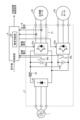
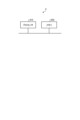
- Fig. 1 is a diagram showing an example of the configuration of an air conditioning device 200 according to embodiment 1.
- the air conditioning device 200 is connected to an AC power source 1, driven by an AC voltage supplied from the AC power source 1, and performs air conditioning control of a space that is an air conditioning control target (not shown).
- Fig. 1 shows an example in which the AC power source 1 is a three-phase power source, but the present invention is not limited to this, and the AC power source 1 may also be a single-phase power source.
- the air conditioning device 200 includes a power converter 2, a compressor 3, a control unit 4, a fan 5, a fan motor 50, and a refrigerant circuit 100.
- the compressor 3 includes a compressor motor 30 and a compression element 31.
- the refrigerant circuit 100 includes a four-way valve 111, a heat source side heat exchanger 112, on-off valves 113a, 113b, an expansion device 121, and a load side heat exchanger 122.
- the refrigerant circuit 100 also includes a compression element 31 included in the compressor 3. As shown in FIG.
- the power converter 2, the compressor 3, the control unit 4, the fan 5, the fan motor 50, and the four-way valve 111, the heat source side heat exchanger 112, and the on-off valves 113a, 113b included in the refrigerant circuit 100 are installed in the outdoor unit 110.
- the expansion device 121 and the load side heat exchanger 122 of the refrigerant circuit 100 are installed in the indoor unit 120.
- the on-off valves 113a and 113b are valves for controlling the flow of refrigerant in the refrigerant circuit 100, and are controlled to open and close by a refrigerant circuit control signal from the control unit 4.
- the control unit 4 can control the flow of refrigerant in the refrigerant circuit 100 by the refrigerant circuit control signal.
- the compressor 3 compresses the refrigerant flowing in the refrigerant circuit 100 to create a refrigeration cycle. That is, in the refrigerant circuit 100, the refrigerant is compressed by the compressor 3, which is driven by the compressor motor 30.
- the power converter 2 converts the first AC voltage supplied from the AC power source 1 into a second AC voltage for driving the compressor motor 30 provided in the compressor 3, and outputs the second AC voltage to the compressor motor 30.
- the power converter 2 also converts the first AC voltage supplied from the AC power source 1 into a third AC voltage for driving the fan motor 50, which is the driving source of the fan 5 and rotates the fan 5, and outputs the third AC voltage to the fan motor 50.
- the power converter 2 also detects the bus voltage, which is the voltage across the main circuit capacitor described later, and detects the motor current of the second AC voltage output from the inverter described later to the compressor motor 30.
- the power converter 2 outputs the detected voltage detection value of the bus voltage and the detected current detection value of the motor current to the control unit 4.
- the control unit 4 acquires a voltage detection value of the bus voltage and a current detection value of the motor current from the power converter 2.
- the control unit 4 also acquires a command value for the air conditioning unit 200 from a user of the air conditioning unit 200 via a remote controller (not shown).
- the command value indicates, for example, an operating mode such as cooling or heating, a set temperature, and the like, but may include other information.
- the control unit 4 uses the acquired information to control the operation of the on-off valves 113a and 113b provided in the power converter 2 and the refrigerant circuit 100. Specifically, the control unit 4 generates a drive signal for generating a second AC voltage in the power converter 2 and outputs it to the power converter 2.
- the drive signal generated by the control unit 4 is for turning on and off the switching elements of the inverter provided in the power converter 2.
- the drive signal generated by the control unit 4 is generated by a general method, and therefore a detailed description is omitted.
- the control unit 4 detects refrigerant leakage from the refrigerant circuit 100 and abnormalities in the compressor 3 using the current detection value of the motor current of the second AC voltage detected by the power converter 2.
- the characteristic feature of this embodiment is the content of control by the control unit 4. Therefore, the configuration of the air conditioning device 200 shown in FIG. 1 is only an example, and the configuration of the air conditioning device 200 is not limited to the example in FIG. 1.
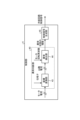
- FIG. 2 is a diagram showing an example of the configuration of the power converter 2 provided in the air conditioning device 200 according to the first embodiment.
- the power converter 2 includes a converter 22, a reactor 23, main circuit capacitors 24a and 24b, inverters 25a and 25b, a current detector 21, and voltage detectors 26a and 26b.
- the converter 22 rectifies the first AC voltage supplied from the AC power source 1.
- the converter 22 may have a boost function.
- FIG. 2 shows an example in which the power converter 2 has a common converter 22 for the inverters 25a and 25b, the power converter 2 can also be configured to have a converter 22 for each of the inverters 25a and 25b, i.e., in the example of FIG. 2, two converters 22 are provided.
- the reactor 23 is provided between the converter 22 and the main circuit capacitors 24a, 24b. Note that the installation position and the number of reactors 23 are not limited to the example in FIG. 2.
- the power converter 2 may have reactors 23 installed in each phase between the AC power source 1 and the converter 22.
- the power converter 2 may have reactors 23 installed in one of the two phases between the AC power source 1 and the converter 22.
- the main circuit capacitor 24a smoothes the voltage rectified by the converter 22 and supplies the smoothed voltage to the inverter 25a.
- the main circuit capacitor 24b smoothes the voltage rectified by the converter 22 and supplies the smoothed voltage to the inverter 25b.
- the power converter 2 is configured to have two main circuit capacitors 24a, 24b, but if the bus voltage is common, the power converter 2 can also be configured to have one main circuit capacitor 24a. In this case, the power converter 2 branches the output destination on the output side of the main circuit capacitor 24a, or to the right of the main circuit capacitor 24a in the example of FIG. 2, with one output destination being the inverter 25a and the other output destination being the inverter 25b.
- the inverter 25a converts the voltage smoothed by the main circuit capacitor 24a into a second AC voltage and outputs it to the compressor motor 30.
- the inverter 25a has three legs, each of which has two switching elements connected in series, although not shown in the figure.
- the inverter 25a turns each switching element on and off in accordance with a drive signal obtained from the control unit 4, thereby converting the voltage smoothed by the main circuit capacitor 24a into a three-phase second AC voltage and outputting the three-phase second AC voltage to the compressor motor 30.
- the inverter 25b converts the voltage smoothed by the main circuit capacitor 24b into a third AC voltage and outputs it to the fan motor 50.
- the inverter 25b has three legs, each of which has two switching elements connected in series, although not shown in the figure.
- the inverter 25b turns each switching element on and off according to the drive signal obtained from the control unit 4, converting the voltage smoothed by the main circuit capacitor 24b into a three-phase third AC voltage, and outputs the three-phase third AC voltage to the fan motor 50.
- the current detection unit 21 detects the motor current, which is the current of the second AC voltage output from the inverter 25a, i.e., the power converter 2, to the compressor motor 30.
- the current detection unit 21 outputs the detected current detection value of the motor current to the control unit 4.
- the current detection value of the motor current detected by the current detection unit 21 is a parameter required for the control calculation of the control unit 4 when generating a drive signal to the inverter 25a to drive the compressor motor 30.
- the current detection value of the motor current detected by the current detection unit 21 is also used for abnormality judgment by the abnormality judgment unit 40 provided in the control unit 4.
- the current detection unit 21 can be realized, for example, by providing an ACCT (Alternating Current Transformer), a DCCT (Direct Current Transformer), a shunt resistor, etc. in a specified phase among the phases connecting the inverter 25a and the compressor motor 30, or by providing a shunt resistor on the lower arm or bus of each phase of the inverter 25a, and using a well-known method of restoring the motor current from the detected current value.
- the current detection unit 21 may detect the current of a specified phase, and the control unit 4 may use a known method to restore the motor current from the detected current value.
- the voltage detection unit 26a detects the voltage across the main circuit capacitor 24a and outputs the detected voltage across the main circuit capacitor 24a to the control unit 4 as a bus voltage.
- the voltage detection unit 26b detects the voltage across the main circuit capacitor 24b and outputs the detected voltage across the main circuit capacitor 24b to the control unit 4 as a bus voltage.
- the abnormality determination unit 40 determines at least the leakage state of the refrigerant from the refrigerant circuit 100 and the abnormal state of the compressor motor 30 based on the current detection value of the motor current output from the power converter 2 to the compressor motor 30. These abnormal states can be determined based on the load state of the compressor motor 30, but in this embodiment, the abnormality determination unit 40 determines the abnormal state by using the current detection value of the motor current output from the power converter 2 to the compressor motor 30 detected by the current detection unit 21 to indirectly determine the load state.
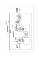
- FIG. 3 is a diagram showing an example of the configuration of the control unit 4 provided in the air conditioning device 200 according to the first embodiment.
- the control unit 4 includes an abnormality determination unit 40 and a control signal generation unit 45.
- the abnormality determination unit 40 includes a coordinate conversion unit 43 and an abnormality detection unit 44. As described above, the operation of generating drive signals for the inverters 25a and 25b in the control unit 4 may be a general operation, so a detailed description will be omitted. In the following, the operation of the abnormality determination unit 40 provided in the control unit 4 will be mainly described. In addition, in the control unit 4, the control signal generation unit 45 is assumed to generate drive signals for the inverters 25a and 25b through normal operation.
- the coordinate conversion unit 43 converts the motor current, which is the current detection value detected by the current detection unit 21, into the d-axis current Id and the q-axis current Iq, which are currents in the dq-axis coordinate system, using the phase ⁇ , which is the electrical angle obtained in the process of the well-known motor position sensorless control calculation process, which corresponds to the rotor position of the compressor motor 30.
- the q-axis current Iq corresponds to the motor torque current component, and since the current flows to balance with the motor load torque, fluctuations in the motor load caused by various factors appear in the q-axis current Iq.
- the abnormality detection unit 44 mainly uses this q-axis current Iq to detect abnormalities according to the principle described below.
- the abnormality detection unit 44 uses the motor rotation frequency of the compressor motor 30 together with the d-axis current Id and q-axis current Iq obtained from the coordinate conversion unit 43, as shown in FIG. 3.
- the motor rotation frequency of the compressor motor 30 is also a parameter used in general motor control, like the above-mentioned phase ⁇ , a detailed description will be omitted.
- the abnormality detection unit 44 uses the current value of the compressor motor 30, in particular the q-axis current Iq, as an index to determine whether or not there is a refrigerant leak.
- the abnormality detection unit 44 compares the q-axis current Iq obtained from the current detection value of the compressor motor 30 with a predefined threshold value, and determines whether or not the q-axis current Iq is smaller than the threshold value, thereby determining whether or not there is a refrigerant leak.
- the threshold value is set, for example, by a person in charge at the manufacturer of the air conditioning device 200, taking into account the operating state of the air conditioning device 200, and is stored in a memory (not shown) of the control unit 4.
- the abnormality detection unit 44 separately distinguishes between an abnormality caused by a refrigerant leak and an abnormality caused by wear of the compressor 3 by controlling as follows.
- the abnormality detection unit 44 can determine whether or not a refrigerant leak has occurred using the current value of the compressor motor 30, particularly the absolute value of the q-axis current Iq, as an index. Since a refrigerant leak is an irreversible abnormality, the abnormality detection unit 44 may determine that an abnormality has occurred when the value remains below a threshold value continuously, or when the rate of change per unit time is below a threshold value.
- the abnormality detection unit 44 can make the same determination using the absolute value of the current of the compressor motor 30 as when the absolute value of the q-axis current Iq is used.
- a load torque fluctuation occurs with one rotation of the compressor motor 30 being one cycle. Therefore, if a frequency analysis is performed on the q-axis current Iq while an abnormality is occurring in the compressor 3, the analysis result will have a motor rotation frequency component. If the compressor 3 is a twin rotary compressor, the analysis result will have a frequency component that is twice the motor rotation frequency. Furthermore, since frictional resistance increases when damage occurs to the sliding parts of the compressor 3, the analysis result will have a load torque fluctuation that is superimposed on the motor rotation frequency component caused by frictional resistance or an integer multiple of the motor rotation frequency component in addition to the load torque fluctuation.
- the abnormality detection unit 44 performs frequency analysis based on the well-known Fourier series expansion principle or FFT (Fast Fourier Transform) analysis to extract the load torque fluctuation of the motor rotation frequency component or the integer multiple component of the motor rotation frequency component caused by friction resistance, and extracts the motor rotation frequency component or the integer multiple component of the motor rotation frequency component contained in the q-axis current Iq. If the value of the extracted frequency component exceeds a predefined threshold, the abnormality detection unit 44 can determine that an abnormality has occurred in the sliding part of the compressor 3 that affects the torque fluctuation of the compressor 3.
- FFT Fast Fourier Transform
- the abnormality detection unit 44 may continuously record the intensity of the motor rotation frequency component or the integer multiple component of the motor rotation frequency component of the compressor 3, and determine that an abnormality has occurred when the intensity of the frequency component continuously exceeds the threshold or the increase rate per specified time exceeds the threshold.
- the thresholds for determining the above-mentioned abnormality may be set based on empirical values, or may be set based on the load of the compressor 3 theoretically determined from the pressure conditions of the refrigeration cycle, i.e., the motor current generated when the motor load of the compressor motor 30 is applied, or preferably the q-axis current Iq as an index.
- the load of the compressor 3 changes depending on the pressure conditions of the compressor 3, the motor rotation frequency, etc., and the range of values to be determined as a normal state also changes, so each threshold may be made variable depending on the pressure conditions of the compressor 3, the motor rotation frequency, etc.
- the processing load when making the threshold variable can be reduced while improving the detection accuracy of abnormalities.
- the q-axis current Iq increases in the air conditioning device 200, it may be due to factors other than an abnormality in the compressor 3.
- an increase in the q-axis current Iq in the air conditioning device 200 is likely to indicate some kind of abnormality, and is at the very least considered to be an abnormal state. Therefore, even if the abnormality detection unit 44 is unable to determine whether or not an abnormality has occurred in the compressor 3 despite the increase in the q-axis current Iq, it may notify the control signal generation unit 45 that an abnormality has occurred in the air conditioning device 200.
- the abnormality detection unit 44 of the abnormality judgment unit 40 can clearly separate the cause of the abnormality appearing in the current of the compressor motor 30 and accurately determine the type of abnormal state.
- the abnormality detection unit 44 can further perform detailed analysis for each frequency component by using FFT analysis. For example, when a small-capacity capacitor, such as a film capacitor, is used as the main circuit capacitor 24a, the fluctuation caused by the AC power source 1 is superimposed on the bus voltage, and the frequency component of the first AC voltage supplied from the AC power source 1 and the integer multiple component of the frequency of the first AC voltage are also superimposed on the q-axis current Iq.
- the integer multiple component is a double component when the AC power source 1 is a single-phase power source, and a six-fold component when the AC power source 1 is a three-phase power source.
- the abnormality detection unit 44 can process the components caused by the first AC voltage supplied from the AC power source 1 after separating or attenuating these frequency components by a well-known filtering process. As a result, the abnormality detection unit 44 can make a judgment after removing the effects of disturbances of the q-axis current Iq that occur due to causes other than those mentioned above, thereby improving the accuracy of the judgment.
- the abnormality detection unit 44 may perform the process of detecting refrigerant leakage from the refrigerant circuit 100 and the process of detecting an abnormality in the compressor 3 in parallel, or may perform them sequentially. When performing them sequentially, the abnormality detection unit 44 first performs the process of detecting refrigerant leakage from the refrigerant circuit 100, and then performs the process of detecting an abnormality in the compressor 3.
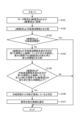
- Figure 4 is a flowchart showing the process of detecting refrigerant leakage from the refrigerant circuit 100 by the abnormality judgment unit 40 of the control unit 4 provided in the air conditioning apparatus 200 according to embodiment 1.
- the coordinate conversion unit 43 converts the motor current acquired from the current detection unit 21 into a d-axis current Id and a q-axis current Iq (step S101) and outputs them to the abnormality detection unit 44.
- the abnormality detection unit 44 compares the q-axis current Iq with a refrigerant leakage threshold for detecting refrigerant leakage from the refrigerant circuit 100 (step S102).
- step S103: Yes the abnormality detection unit 44 determines that refrigerant is not leaking from the refrigerant circuit 100 and ends the process. If the q-axis current Iq is less than the refrigerant leakage threshold (step S103: No), the abnormality detection unit 44 determines that there is a possibility of refrigerant leakage from the refrigerant circuit 100, and further checks whether the state in which the q-axis current Iq is less than the refrigerant leakage threshold continues for a specified first period or more, and compares the rate of change of the q-axis current Iq in the specified second period with the specified rate of change threshold (step S104).
- step S105 If the state in which the q-axis current Iq is less than the refrigerant leakage threshold has not continued for a specified first period or more, and the rate of change of the q-axis current Iq in the specified second period is greater than the specified rate of change threshold (step S105: No), the abnormality detection unit 44 determines that refrigerant is not leaking from the refrigerant circuit 100 and terminates the process.
- the abnormality detection unit 44 determines that refrigerant is leaking from the refrigerant circuit 100 (step S106). The abnormality detection unit 44 notifies the control signal generation unit 45 of the type of abnormal state, in this case, that an abnormality of refrigerant leakage from the refrigerant circuit 100 has occurred (step S107).
- the control signal generating unit 45 can generate a refrigerant circuit control signal for closing the on-off valves 113a and 113b of the refrigerant circuit 100 by acquiring the type of abnormal state indicating the occurrence of a refrigerant leakage abnormality from the abnormality detecting unit 44, and output the refrigerant circuit control signal to the refrigerant circuit 100.
- the control unit 4 detects a refrigerant leak from the refrigerant circuit 100, it generates a refrigerant circuit control signal for closing the on-off valves 113a and 113b and outputs the refrigerant circuit 100.
- the abnormality determining unit 40 periodically repeats the processing of the flowchart shown in FIG. 4.
- the control signal generating unit 45 may generate and output to the power converter 2 a drive signal for converting the first AC voltage to a third AC voltage and outputting the voltage to the fan motor 50, thereby rotating the fan 5 and diffusing the leaked refrigerant.
- the air conditioning device 200 can prevent the refrigerant from accumulating in the same place, thereby preventing the leaked refrigerant from igniting.
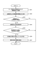
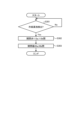
- step S201 is a flowchart showing the process of detecting an abnormality in the compressor 3 by the abnormality determination unit 40 of the control unit 4 provided in the air conditioning apparatus 200 according to embodiment 1.
- the coordinate conversion unit 43 converts the motor current acquired from the current detection unit 21 into a d-axis current Id and a q-axis current Iq (step S201), and outputs them to the abnormality detection unit 44.
- the process of step S201 is the same as the process of step S101 in the flowchart shown in FIG. 4.
- the abnormality detection unit 44 compares the q-axis current Iq with a compressor abnormality threshold for detecting an abnormality in the compressor 3 (step S202).
- step S203: Yes If the q-axis current Iq is equal to or lower than the compressor abnormality threshold (step S203: Yes), the abnormality detection unit 44 determines that no abnormality has occurred in the compressor 3 and ends the process. If the q-axis current Iq is greater than the compressor abnormality threshold (step S203: No), the abnormality detection unit 44 determines that an abnormality may have occurred in the compressor 3 and further performs frequency analysis on the q-axis current Iq (step S204).
- step S205: No the abnormality detection unit 44 determines that no abnormality has occurred in the compressor 3 and ends the process. If the value of the frequency component obtained by the frequency analysis is equal to or greater than the specified frequency component threshold (step S205: Yes), the abnormality detection unit 44 determines that an abnormality has occurred in the compressor 3 (step S206). The abnormality detection unit 44 notifies the control signal generation unit 45 of the type of abnormal state, in this case, that an abnormality has occurred in the compressor 3 (step S207).
- control signal generation unit 45 can stop generating a drive signal for the inverter 25a by acquiring the type of abnormal state indicating that an abnormality has occurred in the compressor 3 from the abnormality detection unit 44.
- the abnormality determination unit 40 periodically repeats the process of the flowchart shown in FIG. 5.
- FIG. 6 is a flowchart showing the process of detecting refrigerant leakage from the refrigerant circuit 100 and the process of detecting an abnormality in the compressor 3 by the abnormality determination unit 40 of the control unit 4 provided in the air conditioning device 200 according to the first embodiment.
- the process shown in steps S101 to S107 is the same as the process of steps S101 to S107 in the flowchart shown in FIG. 4, and the process shown in steps S202 to S207 is the same as the process of steps S202 to S207 in the flowchart shown in FIG. 5. Therefore, a detailed description of the flowchart shown in FIG. 6 is omitted.
- the abnormality determination unit 40 first performs the process of detecting refrigerant leakage from the refrigerant circuit 100, and then performs the process of detecting an abnormality in the compressor 3.
- FIG. 7 is a diagram showing an example of a hardware configuration that realizes the control unit 4 provided in the air conditioning device 200 according to the first embodiment.
- the control unit 4 is realized by a processor 910 and a memory 920.
- the processor 910 is a CPU (also called a central processing unit, processing unit, arithmetic unit, microprocessor, microcomputer, processor, or DSP (Digital Signal Processor)) or a system LSI (Large Scale Integration).
- Examples of the memory 920 include non-volatile or volatile semiconductor memories such as RAM (Random Access Memory), ROM (Read Only Memory), flash memory, EPROM (Erasable Programmable Read Only Memory), and EEPROM (registered trademark) (Electrically Erasable Programmable Read Only Memory). Furthermore, the memory 920 is not limited to these and may be a magnetic disk, optical disk, compact disk, mini disk, or DVD (Digital Versatile Disc).
- the abnormality determination unit 40 of the control unit 4 converts the motor current of the second AC voltage from the inverter 25a to the compressor motor 30 detected by the current detection unit 21 of the power converter 2 into a d-axis current Id and a q-axis current Iq, compares the q-axis current Iq with a threshold value for detecting refrigerant leakage from the refrigerant circuit 100, and compares the q-axis current Iq with a threshold value for detecting an abnormality in the compressor 3. This allows the abnormality determination unit 40 to detect an abnormality that has occurred in the air conditioning device 200 and determine the cause of the abnormality.
- the abnormality determination unit 40 can determine the cause of the abnormality by performing a conversion process to a dq-axis coordinate system used in general control and comparing the values obtained by the conversion process with each threshold value, the processing load can be reduced compared to the case of calculating the power value described in the background art.
- the air conditioning device 200 does not need to add special sensors to the configuration of a general air conditioning device, and can detect abnormalities due to different factors while having a simple configuration.
- the air conditioning device 200 can detect abnormalities caused by different factors, and can respond according to the cause of the abnormality.
- the refrigerant used in the refrigerant circuit 100 of the air conditioning device 200 may be, for example, a fluorine-based refrigerant with a low Global Warming Potential (GWP), or a hydrocarbon-based refrigerant, i.e., HC refrigerant.
- GWP Global Warming Potential
- the refrigerant include a single refrigerant selected from R1234yf, R1234ze, R32, and R290, or a mixture of two or more of these, or a mixture of any of these with another refrigerant.
- the refrigerant include a mixture of R1132(E), or a mixture of R1123.
- refrigerants include mixed refrigerants of R516A, R445A, R444A, R454C, R444B, R454A, R455A, R457A, R459B, R452B, R454B, R447B, R447A, R446A, and R459A.
- Embodiment 2 In the second embodiment, a case will be described in which the air conditioning apparatus is provided with a storage unit.
- FIG. 8 is a first diagram showing an example configuration of a control unit 4a provided in an air conditioning apparatus 200a according to embodiment 2. Note that in the air conditioning apparatus 200a, the configuration other than the control unit 4a is the same as the configuration of the air conditioning apparatus 200 shown in FIG. 1, so in FIG. 8, the configuration other than the control unit 4a is omitted.
- the control unit 4a includes an abnormality determination unit 40a and a control signal generation unit 45.
- the abnormality determination unit 40a includes a coordinate conversion unit 43, a memory unit 42, and an abnormality detection unit 44.
- the memory unit 42 stores the d-axis current Id and the q-axis current Iq after the motor current, which is the current detection value, is converted by the coordinate conversion unit 43 into the d-axis current Id and the q-axis current Iq, which are current values in the dq-axis coordinate system.
- the memory unit 42 stores the d-axis current Id and the q-axis current Iq for a specified period. Note that the memory unit 42 may store only the q-axis current Iq when the d-axis current Id is not used by the abnormality detection unit 44. In other words, the memory unit 42 stores at least the q-axis current Iq for a specified period.
- the abnormality detection unit 44 acquires the d-axis current Id and the q-axis current Iq obtained by the conversion process of the coordinate conversion unit 43 from the storage unit 42. If the d-axis current Id is not stored in the storage unit 42, the abnormality detection unit 44 acquires the q-axis current Iq from the storage unit 42.
- the abnormality detection unit 44 detects refrigerant leakage from the refrigerant circuit 100 and abnormality of the compressor 3 using at least one of the average value or change pattern of the q-axis current Iq in a specified period stored in the storage unit 42.
- a current abnormality may occur due to a momentary power supply fluctuation in the AC power supply 1.
- the abnormality detection unit 44 detects refrigerant leakage from the refrigerant circuit 100 and abnormality in the compressor 3 by using at least one of the average value or change pattern of the q-axis current Iq in a specified period stored in the memory unit 42. This allows the abnormality detection unit 44 to determine whether the detected abnormality is a transient abnormality or an abnormality that should have been detected, thereby suppressing erroneous detection of an abnormality.
- the abnormality detection unit 44 can suppress the influence of sudden fluctuations in the q-axis current Iq when detecting refrigerant leakage from the refrigerant circuit 100 and abnormalities in the compressor 3, for example, by using the average value of the q-axis current Iq over a specified period. Furthermore, based on the information on the time series of the q-axis current Iq stored in the memory unit 42, the abnormality detection unit 44 determines that a normal state exists when there is a change pattern in which an abnormal value relative to the threshold occurs only for an instant and then returns to a normal value, and determines that an abnormality exists when the abnormal value continues to be observed.
- the abnormality determination unit 40a may set a threshold value according to the change over time in the q-axis current Iq by having the air conditioning device 200a perform a learning operation for the purpose of measuring the q-axis current Iq under various parameter settings in the refrigeration cycle, and may store time series data of the q-axis current Iq under normal conditions measured during the learning operation in the memory unit 42, and may set a threshold value based on the stored time series data.
- Parameters included in the parameter settings in the refrigeration cycle include, for example, pressure conditions, condensation temperature, rotation frequency of the compressor motor 30, and the degree of superheat of the refrigerant gas sucked into the compressor 3.
- the abnormality determination unit 40a also collects data during startup of the compressor 3, when sudden changes are likely to occur in the compressor motor 30, and stores it in the memory unit 42. By treating this data in the same way as the time-series data described above, it is possible to improve the accuracy of refrigerant leakage detection, particularly immediately after startup of the compressor 3, and to prevent the air conditioning device 200a from starting up in a state of refrigerant leakage.
- the air conditioning apparatus 200a of embodiment 2 uses the information stored in the memory unit 42 to determine whether an abnormality has occurred, the time it takes to determine that an abnormality has occurred may be longer than that of the air conditioning apparatus 200 of embodiment 1.
- this is also related to the performance of the control unit 4a and the memory unit 42, when considering general processing speeds, the processing speed of the air conditioning apparatus 200a of embodiment 2 is only delayed by several tens of ⁇ s to several ms compared to the processing speed of the air conditioning apparatus 200 of embodiment 1, so this does not pose a problem in practical use.
- the storage unit 42 stores at least the q-axis current Iq, but this is not limiting.
- the storage unit 42 may store the motor current detected by the current detection unit 21 of the power converter 2.
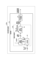
- FIG. 9 is a second diagram showing an example of the configuration of the control unit 4a provided in the air conditioning device 200a according to the second embodiment.
- the storage unit 42 stores the motor current, which is the current detection value.
- the coordinate conversion unit 43 performs coordinate conversion of the motor current stored in the storage unit 42.
- the abnormality detection unit 44 detects refrigerant leakage from the refrigerant circuit 100 and abnormality of the compressor 3 using at least one of the average value or change pattern of the q-axis current Iq in the specified period converted by the coordinate conversion unit 43.
- control unit 4a detects refrigerant leakage from the refrigerant circuit 100 and abnormality of the compressor 3 using at least one of the average value or change pattern of the q-axis current Iq obtained from the motor current, which is the current detection value in the specified period stored in the storage unit 42.
- the air conditioning device 200a can achieve the same effects as with the configuration shown in FIG. 8.
- the abnormality determination unit 40a is provided with a memory unit 42, but this is not limited to the above.
- the memory unit 42 may be external to the abnormality determination unit 40a but internal to the control unit 4a, or external to the control unit 4a but internal to the air conditioning device 200a.
- the air conditioning device 200a includes a memory unit 42 that stores the q-axis current Iq or the motor current, which is a current detection value, and detects refrigerant leakage from the refrigerant circuit 100 and abnormalities in the compressor 3 using at least one of the average value or change pattern of the q-axis current Iq obtained from the q-axis current Iq or the motor current, which is a current detection value, during a specified period stored in the memory unit 42. This allows the air conditioning device 200a to suppress erroneous detection of an abnormality by the abnormality detection unit 44.
- Embodiment 3 a case where the air conditioning apparatus includes a display unit will be described. Note that, hereinafter, a case where the third embodiment is applied to the first embodiment will be described, but the third embodiment can also be applied to the second embodiment.
- FIG. 10 is a diagram showing an example of the configuration of an air conditioning device 200b according to embodiment 3.
- Air conditioning device 200b is obtained by replacing the control unit 4 with a control unit 4b in air conditioning device 200 according to embodiment 1 shown in FIG. 1, and by adding a display unit 41.
- outdoor unit 110b is obtained by replacing the control unit 4 with a control unit 4b in outdoor unit 110 according to embodiment 1 shown in FIG. 1, and by adding a display unit 41.
- the control unit 4b outputs information about the detected abnormality to the display unit 41.
- the abnormality detection unit 44 may output the type of abnormal condition output to the control signal generation unit 45 to the display unit 41 as abnormality information, or the control signal generation unit 45 may output the type of abnormal condition acquired from the abnormality detection unit 44 to the display unit 41 as abnormality information.
- the display unit 41 acquires abnormality information from the control unit 4b, it displays the content of the abnormality detected by the control unit 4b indicated by the abnormality information.
- the display unit 41 may specifically indicate the content of the abnormality in text if the display area of the display unit 41 is large, or may indicate it in the form of an error code if the display area of the display unit 41 is small.
- the air conditioning device 200b is provided with a display unit 41 that displays the details of the abnormality detected by the control unit 4b.
- This allows the air conditioning device 200b to allow the user of the air conditioning device 200b, a service engineer performing maintenance on the air conditioning device 200b, and the like to recognize the details of the abnormality that has occurred in the air conditioning device 200b.
- the display unit 41 displays that an abnormality has occurred in the compressor 3 as the details of the abnormality
- the user or service engineer of the air conditioning device 200b can take action such as stopping the operation of the air conditioning device 200b.
- the display unit 41 is installed in the outdoor unit 110b, but the installation location of the display unit 41 is not limited to the example of FIG. 10.
- the display unit 41 may be installed in the indoor unit 120 of the air conditioning device 200b.
- the control unit 4b may transmit abnormality information via wired communication to a personal computer or the like for operating and monitoring the status of the air conditioning device 200b, or may transmit the information via wireless communication to a remote controller, mobile terminal, or the like for operating and monitoring the status of the air conditioning device 200b.
- Embodiment 4 a case where the air conditioning apparatus includes a switch will be described. Note that, hereinafter, a case where the fourth embodiment is applied to the first embodiment will be described, but the fourth embodiment can also be applied to the second and third embodiments.
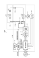
- FIG. 11 is a diagram showing an example of the configuration of an air conditioning device 200c according to the fourth embodiment.
- the configuration of the refrigerant circuit 100 is the same as that of the air conditioning device 200 shown in FIG. 1, so the refrigerant circuit 100 is omitted in FIG. 11.
- the control unit 4 is replaced with a control unit 4c in the air conditioning device 200 of the first embodiment shown in FIG. 1, and switches 20a and 20b are further added.
- the power converter 2c is the power converter 2 of the first embodiment shown in FIG. 1, and switches 20a and 20b are added.
- the switches 20a and 20b are capable of cutting off the supply of the first AC voltage from the AC power source 1.
- the air conditioning device 200c can stop the operation of the power converter 2c by operating the switches 20a and 20b to cut off the supply of the first AC voltage from the AC power source 1.
- the air conditioning apparatus 200c is equipped with on-off valves 113a, 113b in the refrigerant circuit 100, and is therefore capable of operating both the on-off valves 113a, 113b and the switches 20a, 20b.
- the control signal generation unit 45 when the abnormality detection unit 44 detects a refrigerant leak from the refrigerant circuit 100, the control signal generation unit 45 first generates a refrigerant circuit control signal for closing the on-off valves 113a, 113b and outputs it to the refrigerant circuit 100, and then generates a switch drive signal for closing the switches 20a, 20b and outputs it to the switches 20a, 20b.
- control unit 4c detects a refrigerant leak from the refrigerant circuit 100, it first generates a refrigerant circuit control signal for closing the on-off valves 113a and 113b and outputs it to the refrigerant circuit 100, and then generates a switch drive signal for closing the switches 20a and 20b and outputs it to the switches 20a and 20b.
- the air conditioning device 200c can quickly stop the flow of refrigerant in the refrigerant circuit 100, and can reduce the leakage of refrigerant from the refrigerant circuit 100.
Landscapes
- Engineering & Computer Science (AREA)
- Mechanical Engineering (AREA)
- General Engineering & Computer Science (AREA)
- Chemical & Material Sciences (AREA)
- Combustion & Propulsion (AREA)
- Health & Medical Sciences (AREA)
- Biomedical Technology (AREA)
- Physics & Mathematics (AREA)
- Thermal Sciences (AREA)
- Air Conditioning Control Device (AREA)
- Control Of Ac Motors In General (AREA)
Abstract
L'invention concerne un climatiseur (200) comprenant : un circuit de fluide frigorigène (100) dans lequel un fluide frigorigène est comprimé par un compresseur (3) entraîné par un moteur de compresseur (30) ; un convertisseur de puissance (2) qui convertit une première tension CA fournie par une source d'alimentation en CA (1) en une seconde tension CA pour entraîner le moteur de compresseur (30) et délivre la seconde tension CA au moteur de compresseur (30), et détecte également le courant de la seconde tension CA délivrée au moteur de compresseur (30) ; et une unité de commande (4) qui génère et délivre au convertisseur de puissance (2) un signal d'attaque pour générer une seconde tension CA dans le convertisseur de puissance (2), et utilise la valeur de courant détectée du courant de la seconde tension CA détectée par le convertisseur de puissance (2) pour détecter la fuite de fluide frigorigène du circuit de fluide frigorigène (100) et une anomalie dans le compresseur (3).
Priority Applications (2)
| Application Number | Priority Date | Filing Date | Title |
|---|---|---|---|
| JP2025541245A JPWO2025041299A1 (fr) | 2023-08-23 | 2023-08-23 | |
| PCT/JP2023/030308 WO2025041299A1 (fr) | 2023-08-23 | 2023-08-23 | Climatiseur et procédé de détection d'anomalie |
Applications Claiming Priority (1)
| Application Number | Priority Date | Filing Date | Title |
|---|---|---|---|
| PCT/JP2023/030308 WO2025041299A1 (fr) | 2023-08-23 | 2023-08-23 | Climatiseur et procédé de détection d'anomalie |
Publications (1)
| Publication Number | Publication Date |
|---|---|
| WO2025041299A1 true WO2025041299A1 (fr) | 2025-02-27 |
Family
ID=94731679
Family Applications (1)
| Application Number | Title | Priority Date | Filing Date |
|---|---|---|---|
| PCT/JP2023/030308 Pending WO2025041299A1 (fr) | 2023-08-23 | 2023-08-23 | Climatiseur et procédé de détection d'anomalie |
Country Status (2)
| Country | Link |
|---|---|
| JP (1) | JPWO2025041299A1 (fr) |
| WO (1) | WO2025041299A1 (fr) |
Citations (6)
| Publication number | Priority date | Publication date | Assignee | Title |
|---|---|---|---|---|
| JPS4955248U (fr) * | 1972-08-17 | 1974-05-16 | ||
| JP2002005548A (ja) * | 2000-06-19 | 2002-01-09 | Mitsubishi Electric Corp | 可燃性冷媒使用の家電機器 |
| JP2005090925A (ja) * | 2003-09-19 | 2005-04-07 | Toshiba Corp | 冷媒漏れ検知装置及びそれを用いた冷蔵庫 |
| JP2007113874A (ja) * | 2005-10-21 | 2007-05-10 | Daikin Ind Ltd | トレーラー用冷凍装置 |
| JP2007212077A (ja) * | 2006-02-10 | 2007-08-23 | Fujitsu General Ltd | 空気調和機 |
| JP2017221023A (ja) * | 2016-06-07 | 2017-12-14 | 三菱電機株式会社 | 空調機の故障徴候検出装置 |
-
2023
- 2023-08-23 WO PCT/JP2023/030308 patent/WO2025041299A1/fr active Pending
- 2023-08-23 JP JP2025541245A patent/JPWO2025041299A1/ja active Pending
Patent Citations (6)
| Publication number | Priority date | Publication date | Assignee | Title |
|---|---|---|---|---|
| JPS4955248U (fr) * | 1972-08-17 | 1974-05-16 | ||
| JP2002005548A (ja) * | 2000-06-19 | 2002-01-09 | Mitsubishi Electric Corp | 可燃性冷媒使用の家電機器 |
| JP2005090925A (ja) * | 2003-09-19 | 2005-04-07 | Toshiba Corp | 冷媒漏れ検知装置及びそれを用いた冷蔵庫 |
| JP2007113874A (ja) * | 2005-10-21 | 2007-05-10 | Daikin Ind Ltd | トレーラー用冷凍装置 |
| JP2007212077A (ja) * | 2006-02-10 | 2007-08-23 | Fujitsu General Ltd | 空気調和機 |
| JP2017221023A (ja) * | 2016-06-07 | 2017-12-14 | 三菱電機株式会社 | 空調機の故障徴候検出装置 |
Also Published As
| Publication number | Publication date |
|---|---|
| JPWO2025041299A1 (fr) | 2025-02-27 |
Similar Documents
| Publication | Publication Date | Title |
|---|---|---|
| JP4023249B2 (ja) | 圧縮機内部状態推定装置及び空気調和装置 | |
| US8904814B2 (en) | System and method for detecting a fault condition in a compressor | |
| US9762168B2 (en) | Compressor having a control and diagnostic module | |
| US20190170600A1 (en) | Systems and methods for detecting refrigerant leaks in heating, ventilating, and air conditioning (hvac) systems | |
| JP6401658B2 (ja) | 空気調和機 | |
| JP7285969B2 (ja) | モータ制御装置および空気調和装置 | |
| JP2013204871A (ja) | 空気調和機 | |
| CN107655173A (zh) | 运行控制方法、装置、空调系统和计算机可读存储介质 | |
| CN110779161A (zh) | 压缩机过载保护的控制方法、装置及空调器 | |
| JP4932636B2 (ja) | 圧縮機内部状態推定装置及び空気調和装置 | |
| KR20100012077A (ko) | 공기조화기의 전동기 제어장치 | |
| CN111434921B (zh) | 压缩机故障诊断装置、系统、方法及压缩机设备 | |
| WO2025041299A1 (fr) | Climatiseur et procédé de détection d'anomalie | |
| US12372285B2 (en) | Device management system for inverter compressor | |
| JP4670825B2 (ja) | 圧縮機内部状態推定装置及び空気調和装置 | |
| KR20140021174A (ko) | 압축기 및 압축기 제어 방법 | |
| CN113028585A (zh) | 压缩机的控制保护方法和系统 | |
| WO2020184378A1 (fr) | Dispositif de conversion de puissance et dispositif de climatisation l'utilisant | |
| CN113028586B (zh) | 压缩机的控制保护方法、装置和系统 | |
| JP7254569B2 (ja) | 制御装置、空気調和システム、制御方法及びプログラム | |
| JP2016056976A (ja) | 冷凍サイクルにおける圧縮機の脱調検知システム及び脱調検知方法 | |
| Chretien et al. | Seasonal energy efficiency rating improvement of residential HVAC systems using a low power inverter with a PSC compressor | |
| KR20220085386A (ko) | 압축기 이상 판단을 위한 검사 방법 | |
| US20250290678A1 (en) | Refrigeration cycle device | |
| WO2024176355A1 (fr) | Appareil électrique et dispositif à cycle de réfrigération |
Legal Events
| Date | Code | Title | Description |
|---|---|---|---|
| 121 | Ep: the epo has been informed by wipo that ep was designated in this application |
Ref document number: 23949757 Country of ref document: EP Kind code of ref document: A1 |
|
| ENP | Entry into the national phase |
Ref document number: 2025541245 Country of ref document: JP Kind code of ref document: A |
|
| WWE | Wipo information: entry into national phase |
Ref document number: 2025541245 Country of ref document: JP |
|
| NENP | Non-entry into the national phase |
Ref country code: DE |