WO2025041270A1 - Appareil d'installation de récipient et récipient - Google Patents
Appareil d'installation de récipient et récipient Download PDFInfo
- Publication number
- WO2025041270A1 WO2025041270A1 PCT/JP2023/030179 JP2023030179W WO2025041270A1 WO 2025041270 A1 WO2025041270 A1 WO 2025041270A1 JP 2023030179 W JP2023030179 W JP 2023030179W WO 2025041270 A1 WO2025041270 A1 WO 2025041270A1
- Authority
- WO
- WIPO (PCT)
- Prior art keywords
- container
- section
- installation
- installation device
- holding
- Prior art date
- Legal status (The legal status is an assumption and is not a legal conclusion. Google has not performed a legal analysis and makes no representation as to the accuracy of the status listed.)
- Pending
Links
Images


Classifications
-
- G—PHYSICS
- G01—MEASURING; TESTING
- G01N—INVESTIGATING OR ANALYSING MATERIALS BY DETERMINING THEIR CHEMICAL OR PHYSICAL PROPERTIES
- G01N35/00—Automatic analysis not limited to methods or materials provided for in any single one of groups G01N1/00 - G01N33/00; Handling materials therefor
- G01N35/02—Automatic analysis not limited to methods or materials provided for in any single one of groups G01N1/00 - G01N33/00; Handling materials therefor using a plurality of sample containers moved by a conveyor system past one or more treatment or analysis stations
- G01N35/026—Automatic analysis not limited to methods or materials provided for in any single one of groups G01N1/00 - G01N33/00; Handling materials therefor using a plurality of sample containers moved by a conveyor system past one or more treatment or analysis stations having blocks or racks of reaction cells or cuvettes
-
- B—PERFORMING OPERATIONS; TRANSPORTING
- B01—PHYSICAL OR CHEMICAL PROCESSES OR APPARATUS IN GENERAL
- B01L—CHEMICAL OR PHYSICAL LABORATORY APPARATUS FOR GENERAL USE
- B01L9/00—Supporting devices; Holding devices
- B01L9/52—Supports specially adapted for flat sample carriers, e.g. for plates, slides, chips
- B01L9/523—Supports specially adapted for flat sample carriers, e.g. for plates, slides, chips for multisample carriers, e.g. used for microtitration plates
-
- B—PERFORMING OPERATIONS; TRANSPORTING
- B01—PHYSICAL OR CHEMICAL PROCESSES OR APPARATUS IN GENERAL
- B01L—CHEMICAL OR PHYSICAL LABORATORY APPARATUS FOR GENERAL USE
- B01L9/00—Supporting devices; Holding devices
- B01L9/54—Supports specially adapted for pipettes and burettes
- B01L9/543—Supports specially adapted for pipettes and burettes for disposable pipette tips, e.g. racks or cassettes
-
- G—PHYSICS
- G01—MEASURING; TESTING
- G01N—INVESTIGATING OR ANALYSING MATERIALS BY DETERMINING THEIR CHEMICAL OR PHYSICAL PROPERTIES
- G01N35/00—Automatic analysis not limited to methods or materials provided for in any single one of groups G01N1/00 - G01N33/00; Handling materials therefor
- G01N35/02—Automatic analysis not limited to methods or materials provided for in any single one of groups G01N1/00 - G01N33/00; Handling materials therefor using a plurality of sample containers moved by a conveyor system past one or more treatment or analysis stations
-
- B—PERFORMING OPERATIONS; TRANSPORTING
- B01—PHYSICAL OR CHEMICAL PROCESSES OR APPARATUS IN GENERAL
- B01L—CHEMICAL OR PHYSICAL LABORATORY APPARATUS FOR GENERAL USE
- B01L2200/00—Solutions for specific problems relating to chemical or physical laboratory apparatus
- B01L2200/18—Transport of container or devices
-
- G—PHYSICS
- G01—MEASURING; TESTING
- G01N—INVESTIGATING OR ANALYSING MATERIALS BY DETERMINING THEIR CHEMICAL OR PHYSICAL PROPERTIES
- G01N35/00—Automatic analysis not limited to methods or materials provided for in any single one of groups G01N1/00 - G01N33/00; Handling materials therefor
- G01N2035/00178—Special arrangements of analysers
- G01N2035/00207—Handling bulk quantities of analyte
-
- G—PHYSICS
- G01—MEASURING; TESTING
- G01N—INVESTIGATING OR ANALYSING MATERIALS BY DETERMINING THEIR CHEMICAL OR PHYSICAL PROPERTIES
- G01N35/00—Automatic analysis not limited to methods or materials provided for in any single one of groups G01N1/00 - G01N33/00; Handling materials therefor
- G01N35/02—Automatic analysis not limited to methods or materials provided for in any single one of groups G01N1/00 - G01N33/00; Handling materials therefor using a plurality of sample containers moved by a conveyor system past one or more treatment or analysis stations
- G01N35/04—Details of the conveyor system
- G01N2035/0401—Sample carriers, cuvettes or reaction vessels
- G01N2035/0418—Plate elements with several rows of samples
- G01N2035/0425—Stacks, magazines or elevators for plates
-
- G—PHYSICS
- G01—MEASURING; TESTING
- G01N—INVESTIGATING OR ANALYSING MATERIALS BY DETERMINING THEIR CHEMICAL OR PHYSICAL PROPERTIES
- G01N35/00—Automatic analysis not limited to methods or materials provided for in any single one of groups G01N1/00 - G01N33/00; Handling materials therefor
- G01N35/02—Automatic analysis not limited to methods or materials provided for in any single one of groups G01N1/00 - G01N33/00; Handling materials therefor using a plurality of sample containers moved by a conveyor system past one or more treatment or analysis stations
- G01N35/04—Details of the conveyor system
- G01N2035/0401—Sample carriers, cuvettes or reaction vessels
- G01N2035/0427—Sample carriers, cuvettes or reaction vessels nestable or stockable
Definitions
- the present invention relates to a container installation device and a container.
- Patent Document 1 there is a container installation device that installs multiple containers containing chips, reagents, samples, and other contents inside the device in a stacked state and raises and lowers the containers with an elevator (see, for example, Patent Document 1).
- the container installation device described in Patent Document 1 is used in an automatic analyzer for analyzing samples, and is configured to lift multiple stacked part racks up to a rack collection station located above with an elevator.
- Patent Document 1 As explained below, the conventional technology disclosed in Patent Document 1 is desired to make it difficult for foreign objects to get mixed into the stored items and to allow the containers to be removed from the device in the exact order in which they were installed.
- the top of the lower container can come into contact with the bottom of the upper container, which can cause foreign objects to become mixed into the contents of the lower container.
- the present invention provides a container installation device comprising an installation section for installing multiple containers inside, the multiple containers having engagement sections on at least the left and right side portions, and an elevator for raising and lowering the containers inside the installation section, the installation section having multiple insertion openings that open into the front portion and are used to insert the containers into the installation section, an removal opening that opens into the ceiling portion and is used to remove the containers from inside the installation section, multiple holding sections that are provided on the left and right inner wall portions and are used to hold the containers horizontally by engaging with the engagement sections of the containers, and an insertion opening guide section that is provided to block a portion of the insertion opening and is used to guide the insertion of the containers into the insertion opening.
- an installation section for installing multiple containers inside, the multiple containers having engagement sections on at least the left and right side portions, and an elevator for raising and lowering the containers inside the installation section
- the installation section having multiple insertion openings that open into the front portion and are used to insert the containers into the installation section, an removal opening that opens into the ceiling portion and is used to remove
- the present invention makes it possible to prevent foreign objects from entering the contents of a container and improve the order in which the container is used.
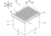
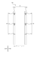
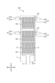
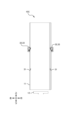
- FIG. 1 is a perspective view of a container installation device and a container according to a first embodiment.
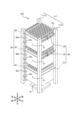
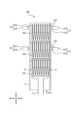
- FIG. 1 is a perspective view of a container installation device according to a first embodiment.
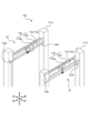
- FIG. 2 is a perspective view of a movable holding part of the container installation device according to the first embodiment.
- FIG. FIG. 2 is a perspective view of the container as viewed from diagonally above to the right.
- 1 is a perspective view of the container as viewed from diagonally below on the right.
- FIG. FIG. FIG. FIG. FIG. 11 is a perspective view of a modified container as viewed from diagonally above right.
- FIG. 11 is a perspective view of a modified container as viewed from diagonally below on the right.
- 4 is an explanatory diagram of a storage state of the container erection device of the first embodiment.
- FIG. 11 is an explanatory diagram (5) of the operation of the container installation device according to the third embodiment.
- FIG. 11 is a perspective view of a container installation device according to a fourth embodiment.
- 13 is an explanatory diagram (1) showing the operation of the container installation device according to the fourth embodiment.
- FIG. 13 is an explanatory diagram (2) of the operation of the container installation device according to the fourth embodiment.
- 13 is an explanatory diagram (3) showing the operation of the container installation device according to the fourth embodiment.
- this embodiment will be described in detail with reference to the drawings. Note that each figure is merely a schematic illustration to allow a sufficient understanding of the invention. Therefore, the present invention is not limited to the illustrated examples. In addition, in each figure, common or similar components are given the same reference numerals, and duplicate explanations thereof will be omitted.
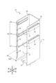
- FIG. 1 is a perspective view of the container erection device 10 and a container 60 according to the first embodiment.
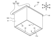
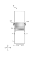
- Fig. 2 is a perspective view of the container erection device 10.
- Fig. 3 is a perspective view of a movable holding part of the container erection device 10.
- a genetic testing device is a device in which it is desired to prevent foreign matter from entering the contents of a container and to improve the order in which the containers are used.
- the container erection device 10 includes an erection section 11, an elevator 12, an operation section 41, and a control section 42. Note that in the example shown in FIG. 1, the operation section 41 and the control section 42 are illustrated, but in other drawings, the operation section 41 and the control section 42 are omitted in order to easily explain the configuration and operation of the container erection device 10 (this also applies to other embodiments).
- the erection section 11 is a component that erects therein a plurality of containers 60.
- the plurality of containers 60 are erected inside the container erection device 10 in a vertically stacked manner.
- the elevator 12 is a component that raises and lowers the container 60 inside the installation section 11 .
- the operation unit 41 is a component that is operated by a user.
- the operation unit 41 is used, for example, to instruct the elevator 12 to start an elevation operation.
- the control unit 42 is a component that controls the operation of each part of the container erection device 10.
- control unit 42 will be described as starting the lifting and lowering operation of the elevator 12 in response to a command input to the container erection device 10 by the user operating the operation unit 41 to start the lifting and lowering operation of the elevator 12.
- the operation of the elevator 12 is automatically controlled by the control unit 42, and is not stopped when the user stops operating the operation unit 41, but is stopped when a predetermined height position is reached and detected by a sensor (not shown) or the like.
- the installation section 11 is formed into a shape by performing sheet metal processing (bending) on a flat metal member.
- the installation section 11 is described as being made of a metal material to ensure strength.
- the installation section 11 may be made of a resin material or the like as long as sufficient strength can be ensured.
- the installation section 11 has multiple insertion openings 21, one removal opening 26, multiple stages of holding sections 30, multiple insertion opening guide sections 22, and an insertion restriction section 35.
- the insertion opening 21 is an opening for inserting the container 60 into the inside of the installation part 11.
- the insertion opening 21 is provided as an opening on the front part of the installation part 11. In this embodiment, it will be described as having three insertion openings 21 provided in the vertical direction.
- the outlet 26 is an opening for removing the container 60 from inside the installation section 11.
- the outlet 26 is provided in the ceiling of the installation section 11.
- the holding portion 30 is a component for holding the container 60 horizontally by engaging with the engagement portion 62 of the container 60.
- the holding portion 30 is configured to have a horizontal surface using a plate-shaped member.
- the holding portion 30 is provided on the left and right inner wall portions of the erection portion 11.
- the holding portion 30 holds the container 60 in a hanging manner when the container 60 is erected, and releases the hold when the container 60 is raised and lowered by the elevator 12. After all the containers 60 have been raised and lowered by the elevator 12, an empty space is formed at the lowest insertion port 21, and the next container 60 is inserted there, so the holding portion 30 holds the container 60.
- the holding parts 30 are arranged so as to protrude into the installation part 11 from the left and right inner wall parts of the installation part 11.
- the lowest holding part 30 is configured as a fixed holding part 31 inside the installation part 11.
- the fixed holding part 31 is configured from a flat plate-like member.
- the holding parts 30 other than the lowest stage are configured as movable holding parts 32 inside the installation part 11 so as to be movable when the container 60 rises with the rise of the elevator 12.
- two movable holding parts 32 are provided.
- the movable holding part 32 has a holding member 33 (FIG. 3) and a movable mechanism 34 for moving the holding member 33. Details of the movable holding part 32 will be described later.
- the spacing T30a, T30b, and T30c (FIG. 7) between the multiple stages of holding parts 30 in the height direction is greater than the height T12 (FIG. 4B) of the container 60 below the engagement part 62. Therefore, the container installation device 10 can prevent the upper container 60 from contacting the lower container 60 when inserting and installing multiple containers 60 inside the installation part 11.
- the insertion port guide section 22 is a component for guiding the insertion of the container 60 into the insertion port 21.
- the insertion port guide section 22 is provided so as to cover a portion of the insertion port 21 of the installation section 11.
- the upper end (upper edge) of the insertion port guide section 22 determines the lower limit insertion position of the container 60.
- the upper end of the insertion port guide section 22 guides the container 60 to a position where the upper container 60 does not come into contact with the foreign matter prevention section 72 provided on the upper surface of the lower container 60 when the container 60 is inserted into the insertion port 21 (when the container 60 is installed in the installation section 11).
- the upper end of the insertion port guide section 22 guides the insertion of the container 60 so that the engagement section of the container 60 does not slip under the holding section 30 of the installation section 11 when the container 60 is inserted into the insertion port 21 (when the container 60 is installed in the installation section 11).
- the lower end (lower edge) of the insertion port guide section 22 defines the upper limit insertion position of the container 60.
- the lower end of the insertion port guide section 22 guides the container 60 to a position where the foreign matter intrusion prevention section 72 provided on the upper surface of the lower container 60 does not contact the upper container 60 when the container 60 is inserted into the insertion port 21 (when the container 60 is installed in the installation section 11).
- the container installation device 10 regulates the vertical position of the container 60 inserted into the insertion port 21 through the gap formed between the lower end (lower edge) and upper end (upper edge) of the two insertion port guide sections 22 arranged vertically.
- Such an insertion port guide section 22 can prevent the upper container 60 from interfering with the foreign matter intrusion prevention section 72 of the lower container 60.
- the widthwise end (right side) of the insertion port guide section 22 determines the left and right positions of the container 60. That is, the widthwise end of the insertion port guide section 22 guides the container 60 to a position in the opposite direction from the insertion port guide section 22 when the container 60 is inserted into the insertion port 21 (when the container 60 is installed in the installation section 11). In addition, the widthwise end of the insertion port guide section 22 guides the container 60 to a position in the opposite direction from the insertion port guide section 22 when the container 60 is raised. Such a widthwise end of the insertion port guide section 22 can keep the position of the container 60 constant.
- the insertion port guide portion 22 is provided on one side of the insertion port 21 of the installation section 11 to restrict the insertion direction of the container 60 to a certain direction (in this embodiment, the longitudinal direction of the container 60).
- the insertion port 21 has an asymmetric structure by providing the insertion port guide portion 22 on one side of the insertion port 21 to prevent the container 60 from being installed in the wrong orientation.
- the insertion port guide portion 22 is provided on the left side of the insertion port 21 of the installation section 11.
- Such a container installation device 10 allows the user to insert the container 60 in the back direction (rear direction) while the insertion port guide portion 22 moves the container 60 to the right. This allows the container installation device 10 to guide the insertion of the container 60 so that the notch portion 65 of the container 60 fits into the insertion restriction portion 35 of the installation section 11.
- the insertion port guide section 22 is configured from a rectangular plate-like member.
- the shape of the insertion port guide section 22 is not limited to the illustrated example.
- the upper edge portion of the insertion port guide section 22 is provided at the same height as the portion of the holding section 30 that holds the container 60 so as to contact the bottom surface of the engagement section 62 (Figs. 4A to 4E) of the container 60 when the container 60 is inserted, thereby guiding the insertion of the container 60.
- the container installation device 10 can cause the insertion port guide section 22 to function as a reinforcement for the left holding section 30 against the vertical load of the container 60.
- the width W22 (Fig. 2) of the insertion opening 21 where the insertion opening guide section 22 is provided is shorter than the vertical width L11 (Fig. 4A) of the storage section 61 of the container 60, which will be described later. In other words, “horizontal width W22 (Fig. 2) ⁇ vertical width L11 (Fig. 4A)". Also, the width W22 (Fig. 2) of the insertion opening 21 where the insertion opening guide section 22 is provided is shorter than the vertical width L12 (Fig. 4C) of the engagement section 62 of the container 60, which will be described later. In other words, “horizontal width W22 (Fig. 2) ⁇ vertical width L12 (Fig. 4C)".
- Such a container erection device 10 can limit the insertion direction of the container 60 into the insertion opening 21 of the erection section 11 to only the front-to-rear direction of the container 60.
- the width W22 (Fig. 2) of the insertion opening 21 where the insertion opening guide section 22 is provided is longer than the width W11 (Fig. 4A) of the storage section 61 of the container 60 described later, and is shorter than the width W12 (Fig. 4C) of the engagement section 62 of the container 60 described later.
- width W12 (Fig. 4A) ⁇ width W22 (Fig. 2) ⁇ width W12 (Fig. 4C)
- Such a container erection device 10 can insert the container 60 into the erection section 11 only when the storage section 61 (Fig. 4A) of the container 60 described later passes through the insertion opening 21 where the insertion opening guide section 22 is provided. Therefore, the container erection device 10 can prevent the upper container 60 from contacting the lower container 60 when inserting multiple containers 60 into the erection section 11.
- the insertion restriction portion 35 is a component that restricts the insertion of the container 60 inserted in the wrong direction into the installation portion 11.
- the insertion restriction portion 35 is provided in a protruding shape so as to fit into a notch 65 (FIGS. 4A to 4C) provided at a corner of the engagement portion 62 (FIGS. 4A to 4E) of the container 60.
- the insertion restriction portion 35 is provided at a corner of the back (rear) of the installation portion 11 on the side opposite the insertion port guide portion 22 (in this embodiment, the right side).
- Such a container installation device 10 has the user insert the container 60 in the back direction (rear direction) with the container 60 shifted to the right by the insertion port guide portion 22.
- the container installation device 10 can restrict the insertion of a container 60 that has been inserted into the installation section 11 in an incorrect direction by the insertion restriction section 35.
- the position and shape of the insertion restriction section 35 are not limited to those shown in the illustration, as long as it is possible to restrict the insertion of a container 60 that has been inserted into the installation section 11 in an incorrect direction.
- the movable holding portion 32 has a holding member 33 that engages with an engagement portion 62 of the container 60, a hinge shaft 34a (shaft portion) that axially supports the holding member 33 so as to be rotatable, and a kick spring 34b (urging member) that urges the holding member 33 toward the inside of the container 60.
- the hinge shaft 34a (shaft portion) and the kick spring 34b (urging member) constitute a movable mechanism 34 that moves the holding member 33.
- the holding member 33 is configured to rotate around the hinge shaft 34a (shaft portion), and is urged toward the inside of the container 60 by the kick spring 34b (urging member).
- the retaining member 33 is described as being made of a metal material to ensure strength.
- the retaining member 33 may be made of a resin material or the like as long as sufficient strength can be ensured.
- the holding member 33 has an inclined surface, and when the container 60 rises in conjunction with the rise of the elevator 12, the engagement portion 62 (Figs. 4A to 4E) of the container 60 abuts against the inclined surface. At this time, the holding member 33 is pushed outward by the engagement portion 62 (Figs. 4A to 4E) of the container 60, and retreats in the direction from the inside to the outside of the container 60. Then, when the container 60 rises further, the holding member 33 is released from abutment with the engagement portion 62 (Figs. 4A to 4E) of the container 60. At this time, the holding member 33 is pushed inward by the kick spring 34b (biasing member), and advances in the direction from the outside to the inside of the container 60.
- the kick spring 34b biasing member
- the holding member 33 has a horizontal surface 33a and a regulating surface 33b.
- the horizontal surface 33a is a surface that holds the container 60 horizontally by engaging (supporting) with the engaging portion 62 (Figs. 4A to 4E) of the container 60 when the holding member 33 has advanced into the container 60.
- the regulating surface 33b is a surface that stops the rotation of the holding member 33 and maintains the horizontal surface 33a in the horizontal direction by abutting against the outer wall surface of the erection portion 11 (or the wall surface of a separately provided member not shown) when the holding member 33 has advanced into the container 60.
- Figure 4A is a perspective view of the container 60 as viewed from diagonally above right.
- Figure 4B is a perspective view of the container 60 as viewed from diagonally below right.
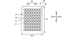
- Figure 4C is a top view of the container 60.
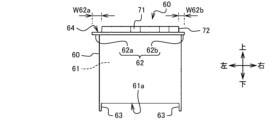
- Figure 4D is a front view of the container 60.
- Figure 4E is a front cross-sectional view of the container 60.
- the container 60 is described as being configured as a tip rack on which a plurality of tips are mounted.
- the container 60 may also be one that stores reagents, specimens, etc.
- the container 60 has an asymmetrical structure so as to prevent the container 60 from being installed in the wrong orientation.
- the container 60 includes a storage section 61, an engagement section 62, a foreign matter prevention section 72, legs 63, and a notch 65.
- the engagement portion 62 is provided so as to protrude from at least the left and right side portions of the container 60 by different protrusion amounts.
- the protrusion amount W62a of the left engagement portion 62a is greater than the protrusion amount W62b of the right engagement portion 62b.
- protrusion amount W62a of engagement portion 62a > protrusion amount W62b of engagement portion 62b.
- Such a container 60 can restrict the insertion direction of the container 60 when the container 60 is inserted into the insertion port 21 of the installation part 11 in which the insertion port guide part 22 is provided.
- the engagement part 62a since the protrusion amount W62a of the engagement part 62a of such a container 60 is large, the engagement part 62a reaches the holding part 30 of the installation part 11 after passing through the insertion port 21 of the installation part 11 in which the insertion port guide part 22 is provided. Therefore, the container 60 can have the engagement part 62a engage (support) well with the holding part 30 of the installation part 11.
- the container 60 is also configured such that the engagement portion 62 protrudes outward from the storage portion 61. Therefore, when a user grips the container 60, the engagement portion 62 functions as an anti-slip device, preventing the container 60 from being accidentally dropped by the user. Furthermore, when the container 60 is erected on the erection portion 11 of the container erection device 10, the engagement portion 62 engages with the holding portion 30, thereby preventing the container 60 from being erected in a position where it should not be erected (a position other than the erection completion position).
- the container 60 has a foreign matter intrusion prevention section 72 that protrudes above the ceiling surface 64.
- the container 60 also has a hollow space formed between the legs 63.
- the height of the hollow space is set to a height that forms a gap 73 between the bottom surface 61a of the storage section 61 in the upper container 60 and the top of the foreign matter intrusion prevention section 72 in the lower container 60 when multiple containers 60 are stacked one on top of the other inside the container installation device 10 so that the contact surface 63a of the leg 63 of the upper container 60 abuts against the lower container 60.
- the container 60 can be modified, for example, as a container 160 shown in Fig. 5A and Fig. 5B.
- Fig. 5A is a perspective view of the modified container 160 as viewed from diagonally above and to the right.
- Fig. 5B is a perspective view of the modified container 160 as viewed from diagonally below and to the right.
- the legs 63 are provided on the four side surfaces of the storage section 61, front, back, left and right, so as to protrude downward.
- the legs 63 are provided on the lower part of the four side surfaces of the container 60.
- this type of container 160 Compared to container 60 (FIGS. 4A and 4B), this type of container 160 has no opening between the legs 63, so when multiple containers 160 are inserted into the installation section 11, it is not possible to make it difficult for the upper container 160 to come into contact with the lower container 160.
- container 160 is provided at the bottom of the four side portions of container 160, the strength of the legs 63 can be improved compared to container 60. Such a container 160 can suppress bending and breakage of the legs 63.
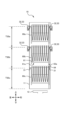
- FIG. 6 is an explanatory diagram of the container erection device 10 in a stored state.
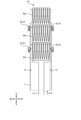
- Figures 7 to 11 are explanatory diagrams of the operation of the container erection device 10.
- the explanation will be given assuming that a user inserts a container 60 into the erection section 11.
- the container erection device 10 operates as follows in order to standardize the erection order and the use order and to maximize the number of additional erections.
- the container installation device 10 installs a plurality of containers 60 in a stacked state inside the installation section 11.
- the user inserts all of the containers 60 into the insertion openings 21 of the installation section 11, the number of containers that can be accommodated in the installation section 11, so that there are no gaps in the insertion openings 21 of the installation section 11.
- the containers 60 are inserted from the upper insertion opening 21 to the lower insertion opening 21 in order of earliest use. That is, the user inserts, for example, the container 60a that is used first into the top insertion opening 21, the container 60b that is used second into the middle insertion opening 21, and the container 60c that is used third earliest (latest) into the bottom insertion opening 21.
- the user can change the order in which the containers 60 are inserted, so long as the user can insert the containers 60 into the insertion slot 21 of the row that corresponds to the order of use. Therefore, the user can, for example, first insert the container 60b, which is the second earliest to be used, into the insertion slot 21 of the middle row, then insert the container 60c, which is the third earliest to be used, into the insertion slot 21 of the bottom row, and then insert the container 60a, which is the first earliest to be used, into the insertion slot 21 of the top row.
- each container 60 is installed in a state where it is spaced apart from the other containers 60. That is, the container installation device 10 installs container 60a by holding the engaging section 62 of container 60a with the movable holding section 32 of the upper tier. The container installation device 10 also installs container 60b by holding the engaging section 62 of container 60b with the movable holding section 32 of the lower tier. The container installation device 10 also installs container 60c by holding the engaging section 62 of container 60c with the fixed holding section 31.
- the container erection device 10 raises the elevator 12 (see arrow A11). At this time, the first container 60c from the bottom rises. At that time, the engagement portion 62 of the first container 60c from the bottom rises and moves away from the fixed holding portion 31. Then, the ground contact surface 63a of the second container 60b from the top abuts against the first container 60c from the bottom. At this time, the container erection device 10 forms a gap 73 between the bottom surface 61a of the storage portion 61 of the second container 60b from the top and the top of the foreign matter intrusion prevention portion 72 of the first container 60c from the bottom.
- the container installation device 10 raises the elevator 12, the containers 60a, 60b, and 60c rise (see arrow A12).
- the engagement portion 62 of the second container 60b from the top rises and moves away from the movable holding portion 32 in the lower tier.
- the ground contact surface 63a of the first container 60a from the top abuts against the second container 60b from the top.
- the container installation device 10 forms a gap 73 between the bottom surface 61a of the storage portion 61 of the first container 60a from the top and the top of the foreign matter intrusion prevention portion 72 of the second container 60b from the top.
- the engagement portion 62 of the first container 60a from the top rises and moves away from the movable holding portion 32 in the upper tier.
- the engaging portion 62 of the container 60 comes into contact with the holding member 33 of the movable holding part 32.
- the holding member 33 of the movable holding part 32 is pushed by the engaging portion 62 of the container 60 and rotates in the backward direction.
- the engaging portion 62 of the container 60 and the holding member 33 of the movable holding part 32 are released from contact with each other.
- the holding member 33 of the movable holding part 32 is pushed by the kick spring 34b (biasing member) and rotates in the forward direction.
- the holding member 33 stops rotating when the restricting surface 33b comes into contact with the outer wall surface of the erection part 11 (or the wall surface of a separately provided member not shown). At this time, the horizontal surface 33a of the holding member 33 is arranged in the horizontal direction.
- the container installation device 10 raises the elevator 12
- the containers 60a, 60b, and 60c rise further (see arrow A13).
- the first container 60a from the top is sent out from the removal port 26 to the outside of the installation section 11.
- the second container 60b from the top is installed on the upper movable holding section 32. The user removes the first container 60a from the top that has been sent out to the outside of the installation section 11.
- the container erection device 10 lowers the elevator 12 (see arrow A14). Then, the containers 60b and 60c are lowered. At this time, the container erection device 10 holds the engagement portion 62 of the container 60b with the upper movable holding portion 32 and erects the container 60b. The container erection device 10 also holds the engagement portion 62 of the container 60c with the lower movable holding portion 32 and erects the container 60c. Since an empty space is formed in the lowest insertion port 21 of the erection portion 11, the user can insert the next container 60 into the lowest insertion port 21.
- Such a container erection device 10 can erect the containers 60 in the same order as the order in which the containers 60 are used. Therefore, the container erection device 10 can operate by removing the containers 60 from the device and using them in the order in which they were erected.
- the container installation device 10 includes an installation section 11 and an elevator 12.
- the installation section 11 is a component that installs a plurality of containers 60 having engagement sections 62 on at least the left and right side surfaces.
- the elevator 12 is a component that raises and lowers the containers 60 inside the installation section 11.
- the installation section 11 has a plurality of insertion openings 21 for inserting the containers 60 into the installation section 11, an ejection opening 26 for removing the containers 60 from the installation section 11, a plurality of holding sections 30 for holding the containers 60 horizontally by engaging with the engagement sections 62 of the containers 60, and an insertion opening guide section 22 for guiding the insertion of the containers 60 into the insertion openings 21.
- the plurality of insertion openings 21 are provided to open on the front surface of the installation section 11.
- the ejection opening 26 is provided to open on the ceiling of the installation section 11.
- the holding portions 30 are provided on the left and right inner wall portions of the bridging portion 11.
- the insertion opening guide portions 22 are provided so as to close a part of the insertion opening 21 of the bridging portion 11.
- the container erection device 10 guides the insertion position of the container 60 with the insertion port guide section 22. Therefore, the container erection device 10 can insert the container 60 without the upper container 60 colliding with the lower container 60. Therefore, the container erection device 10 can prevent foreign objects from entering the contents 71 inside the container 60. Furthermore, the container erection device 10 can erect the containers 60 in the same order as the order in which the containers 60 are used. Therefore, the container erection device 10 can operate by removing and using the containers 60 in the order in which they were erected. Therefore, the container erection device 10 can prevent foreign objects from entering and improve the order in which the containers 60 are used.
- the insertion port guide portion 22 may be provided on either the left or right side of the insertion port 21 of the installation portion 11.
- the container installation device 10 allows the user to insert the container 60 in the rearward direction while the container 60 is moved in the direction opposite to the side where the insertion port guide section 22 is provided. Therefore, the container installation device 10 can effectively guide the insertion of the container 60.
- the upper edge portion of the insertion port guide portion 22 may be provided at the same height as the portion of the holding portion 30 that holds the container 60.
- the container erection device 10 guides the insertion height position of the container 60 with the upper edge portion of the insertion port guide section 22. Therefore, the container erection device 10 can insert the container 60 so that the upper container 60 does not collide with the lower container 60. Therefore, the container erection device 10 can prevent foreign objects from entering the contents 71 inside the container 60.
- the holding portion 30 is preferably positioned so as to protrude into the interior of the installation portion 11 from the left and right inner wall portions of the installation portion 11.
- the container installation device 10 can install the container 60 well inside the installation section 11.
- the lowest stage holding section 30 is configured as a fixed holding section 31 inside the erection section 11, while the holding sections 30 other than the lowest stage are configured as movable holding sections 32 inside the erection section 11 so as to be movable when the container 60 rises in conjunction with the rise of the elevator 12.
- the container installation device 10 can send out the container 60 installed on the movable holding part 32 and the fixed holding part 31 toward the removal outlet 26 by raising the elevator 12.
- the movable holding portion 32 may be configured to include a holding member 33 that engages with the engagement portion 62 of the container 60, a hinge shaft 34a (shaft portion) that axially supports the holding member 33 so that it can rotate freely, and a kick spring 34b (biasing member) that biases the holding member 33 toward the inside of the container 60.
- the container erection device 10 can move the holding member 33 toward the inside of the container 60 by using the kick spring 34b (biasing member).
- the container erection device 10 rotates backward and then forward. This container erection device 10 can erect the containers 60 in the order of use.
- the spacing T30a, T30b, and T30c (FIG. 7) between the multiple stages of holding sections 30 in the height direction may be greater than the height T12 (FIG. 4B) of the container 60 below the engagement section 62.
- the container installation device 10 can prevent the upper container 60 from coming into contact with the lower container 60 when multiple containers 60 are inserted and installed inside the installation section 11.
- the installation section 11 may have an insertion restriction section 35 that restricts the insertion of a container 60 that has been inserted into the installation section 11 in the wrong direction.
- the container installation device 10 when the container 60 is inserted into the installation section 11 in the wrong direction, the insertion restriction section 35 can stop the container 60 from being fully inserted. Therefore, the container installation device 10 can prevent the user from fully inserting the container 60 in the wrong direction.
- the installation section 11 is configured in a [shape by subjecting a flat metal member to sheet metal processing (bending).
- the holding section 30 is preferably configured to have a horizontal surface by a plate-shaped member.
- the container erection device 10 can form the erection section 11 by deforming a plate-like member into a shape.
- the container erection device 10 can form the erection section 11 at low cost.
- the container 60 is a container that is vertically stacked inside the container erection device 10.
- the container 60 includes a storage section 61 for storing an object 71 inside, an engagement section 62 provided at least on the left and right side surfaces and for engaging with a holding section 30 provided on the left and right inner wall sections of the container erection device 10, a foreign matter intrusion prevention section 72 provided at the upper part and for preventing foreign matter from intruding inside, and a leg section 63 provided at the lower part and for forming a hollow space inside.
- a storage section 61 for storing an object 71 inside
- an engagement section 62 provided at least on the left and right side surfaces and for engaging with a holding section 30 provided on the left and right inner wall sections of the container erection device 10
- a foreign matter intrusion prevention section 72 provided at the upper part and for preventing foreign matter from intruding inside
- a leg section 63 provided at the lower part and for forming a hollow space inside.
- the height of the hollow space is set to a height that forms a gap 73 between the bottom surface of the storage section 61 of the upper container 60 and the top of the foreign matter intrusion prevention section 72 of the lower container 60 when the multiple containers 60 are vertically stacked inside the container erection device 10.
- the container 60 according to this embodiment can prevent the upper container 60 from coming into contact with the lower container 60 when multiple containers 60 are mounted on the container mounting device 10.
- the engagement portion 62 may be provided so as to protrude from at least the left and right side portions of the container 60 by different protrusion amounts W62a, W62b.
- the container 60 according to this embodiment can restrict the insertion direction when it is installed on the container installation device 10.
- the protrusion amount W62a of the engagement portion 62a of this container 60 is large, the engagement portion 62a reaches the holding portion 30 of the installation portion 11 after passing through the insertion port 21 of the installation portion 11 in which the insertion port guide portion 22 is provided. Therefore, the container 60 can have the engagement portion 62a engage (support) well with the holding portion 30 of the installation portion 11.
- the container 60 has a rectangular shape when viewed from above, and preferably has a notch 65 at one of its four corners that is formed so that the insertion restriction section 35 provided inside the container installation device 10 can fit into it.
- the insertion restriction portion 35 provided inside the container erection device 10 does not fit into the notch 65, and the container is not inserted completely and stops midway. This prevents the user from inserting the container 60 completely into the container erection device 10 in the wrong direction.
- the container 60 according to this embodiment may have a different length in one direction than in the other direction when viewed from above.
- the user When inserting the container 60 according to this embodiment into the container installation device 10, the user can be guided to insert the container 60 in the direction that is longer in length.
- the legs 63 may be provided only on the lower parts of the left and right side surfaces of the container 60.
- the container 60 has openings between the legs 63 at the front and rear, making it difficult for the upper container 60 to come into contact with the lower container 60 when multiple containers 60 are inserted into the installation section 11. Therefore, the container 60 can easily prevent foreign objects from entering the contents 71 inside the container 60.
- the engagement portion 62 may be provided in the form of a protrusion so as to function as an anti-slip device.
- the engagement portion 62 functions as an anti-slip device, so the container 60 can be prevented from being accidentally dropped by the user.
- the legs 63 may be configured to be provided on the lower part of the four side surfaces of the container 60.
- the container 60 has legs 63 at the bottom of the four side surfaces of the container 160, so the strength of the legs 63 can be improved compared to the container 60.
- the container installation device 10 can prevent the intrusion of foreign matter and improve the order in which the containers 60 are used.
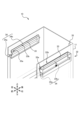
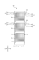
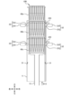
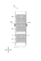
- FIG. 12 is a perspective view of the container erection device 10A according to the second embodiment.
- Fig. 13 is a front view of the container erection device 10A.
- Fig. 14 is an explanatory diagram of the container erection device 10A.
- Fig. 15 is a perspective view of the movable holding part 32 of the container erection device 10A.
- the container installation device 10A of this embodiment 2 differs from the container installation device 10 of embodiment 1 (see Figure 2) in that it has an installation part 111 instead of the installation part 11.
- the installation section 111 is configured in a frame shape using rod-shaped members.
- the installation section 111 is composed of a left installation section 111a and a right installation section 111b.
- An insertion restriction section 35 is provided at the rear of the right installation section 111b.
- an insertion port guide section 22a is provided on the left installation section 111a.
- the insertion port guide section 22a is configured in a ] shape using a rod-shaped member.
- the upper edge of the insertion port guide section 22a is provided at the same height as the part of the holding section 30 that holds the container 60 so that it comes into contact with the bottom surface of the engagement section 62 (Figs. 4A to 4E) of the container 60 when the container 60 is inserted, thereby guiding the insertion of the container 60.
- the container installation device 10A of this embodiment 2 has three insertion openings 21 on the front portion, and one removal opening 26 (FIG. 12) on the ceiling portion, similar to the container installation device 10 of embodiment 1 (see FIG. 2).
- the container erection device 10A erects multiple containers 60 in a stacked state inside the erection section 111. Each container 60 is inserted from the upper insertion port 21 to the lower insertion port 21 in the order of earliest use.
- the container erection device 10A of this embodiment 2 operates in the same manner as the container erection device 10 of embodiment 1 (see Figure 2).
- the fixed holding part 31 of the container erecting device 10A is made of a flat plate-like member.
- the movable holding part 32 of the container erecting device 10A is made of a rod-like member and is frame-like so as to have a horizontal surface.
- the movable holding part 32 has a holding member 133 that engages with the engagement part 62 of the container 60 and a movable mechanism 134 that moves the holding member 133.
- the holding member 133 has a plate part 133a that engages with the engagement part 62 of the container 60 and a shaft part 133b that supports the plate part 133a so that it can rotate freely.
- the holding member 133 is made of a plurality of flat plate-like members joined together.
- the movable mechanism 134 has a regulating member 134a that regulates the rotation of the holding member 133 and a kick spring 134b (urging member) that urges the holding member 133 toward the inside of the container 60.
- the holding member 133 is described as being made of a metal material to ensure strength.
- the holding member 133 may be made of a resin material or the like as long as sufficient strength can be ensured.
- the engaging portion 62 of the container 60 abuts against the holding member 133.
- the holding member 133 is pushed outward by the engaging portion 62 of the container 60, and retreats in a direction from the inside to the outside of the container 60.
- the holding member 133 is released from abutment with the engaging portion 62 of the container 60.
- the holding member 133 is pushed inward by the kick spring 134b (biasing member), and advances in a direction from the outside to the inside of the container 60.
- the holding member 133 pushed inward by the kick spring 134b stops rotating in a state advanced into the interior of the container 60, as a portion of the holding member 133 abuts against the regulating member 134a.
- the holding member 133 provided on the left-side bridge portion 111a and the holding member 133 provided on the right-side bridge portion 111b stop at an angle that allows the container 60 to be held horizontally between them.
- the installation section 111 can be configured by a rod-shaped member.
- the fixed holding section 31 can be configured by a flat plate-shaped member.
- the movable holding section 32 can be configured by a rod-shaped member.
- the fixed holder 31 of the container erecting device 10A is configured by a flat plate-like member.
- the container erecting device 10A can configure the holding member 133 of the movable holder 32 by a rod-like member.
- This container erection device 10A can prevent the intrusion of foreign matter and improve the order of use of the containers 60. Furthermore, compared to the container installation device 10 of embodiment 1, this container installation device 10A has a configuration in which the side of the installation section 111 is open, so that the user can visually check the condition of each container 60 installed on the installation section 111 from the side of the installation section 111.
- Fig. 16 is a perspective view of the container erection device 10B according to the third embodiment.
- Fig. 17 is a front view of the container erection device 10B.
- the container installation device 10B of this embodiment 3 differs from the container installation device 10 of embodiment 1 (see Figure 2) in that the movable holding part 32 is composed of a holding member 233 and a solenoid 234 (electrically-operated member) and in that it has a container detection sensor 235.
- the holding member 233 is a member that engages with the engagement portion 62 of the container 60.
- the holding member 233 is configured to slide in the left-right direction.
- the solenoid 234 is an electrically-driven member that selectively advances (advances) or retreats the holding member 233 by sliding it relative to the internal space inside the installation section 11 .
- the container detection sensor 235 is a sensor that detects the container 60 (particularly the engagement portion 62 of the container 60 ) rising inside the installation portion 11 .
- the movable holding portion 32 is configured such that the holding member 233 is slidably moved by a solenoid 234 (electrically-driven member), but is not limited to the mechanism shown in the figure.
- Figures 18 to 22 are explanatory diagrams of the operation of the container erection device 10B.
- the container erection device 10B In the initial state, the container erection device 10B is in a state in which the holding members 233 of each stage are advanced (advanced into the internal space inside the erection section 11).
- the container installation device 10B installs multiple containers 60 in a stacked state inside the installation section 11. Each container 60 is inserted from the upper insertion port 21 to the lower insertion port 21 in the order of earliest use. The user inserts each tier of containers 60 into the installation section 11 to install them. At this time, each container 60 is installed in a state separated from the other containers 60. In other words, the container installation device 10B installs container 60a with the upper tier movable holding section 32. The container installation device 10B also installs container 60b with the lower tier movable holding section 32. The container installation device 10B also installs container 60c with the fixed holding section 31.
- the container installation device 10B raises the elevator 12 (see arrow B11).
- the first container 60c from the bottom rises.
- the engagement part 62 of the first container 60c from the bottom rises and moves away from the fixed holding part 31.
- the ground surface 63a (FIG. 4E) of the second container 60b from the top abuts against the first container 60c from the bottom.
- the container installation device 10B drives the solenoid 234 of the lower movable holding portion 32 to move the holding member 233 of the lower movable holding portion 32 backward.
- the container installation device 10B raises the elevator 12
- the contact surface 63a (FIG. 4E) of the first container 60a from the top abuts against the second container 60b from the top, and containers 60a, 60b, and 60c rise (see arrow B12).
- the engagement portion 62 (FIG. 4E) of the first container 60a from the top rises and separates from the upper movable holding portion 32.
- the upper container detection sensor 235 detects the rise of container 60a (particularly the engagement portion 62 (FIG. 4E) of container 60a).
- the container installation device 10B drives the solenoid 234 of the upper movable holding portion 32 to retract the holding member 233 of the upper movable holding portion 32.
- the container installation device 10B raises the elevator 12, the containers 60a, 60b, and 60c rise further (see arrow B13). As a result, the first container 60a from the top is sent out from the removal port 26 to the outside of the installation section 11.
- the engagement part 62 (FIG. 4E) of the second container 60b from the top is positioned higher than the upper container detection sensor 235. Therefore, the upper container detection sensor 235 detects the rise of the container 60b (particularly the engagement part 62 (FIG. 4E) of the container 60b).
- the container installation device 10B drives the solenoids 234 of the upper and lower movable holding parts 32 to advance the holding members 233 of the upper and lower movable holding parts 32. The user then takes out the first container 60a from the top that has been sent out to the outside of the installation section 11.
- the container erection device 10B lowers the elevator 12 (see arrow B14). Then, the containers 60b and 60c are lowered. At this time, the container erection device 10B holds the engagement portion 62 (FIG. 4E) of the container 60b with the upper movable holding portion 32 and erects the container 60b. The container erection device 10B also holds the engagement portion 62 (FIG. 4E) of the container 60c with the lower movable holding portion 32 and erects the container 60c. Since an empty space is formed in the lowest insertion port 21 of the erection portion 11, the user can insert the next container 60 into the lowest insertion port 21.
- Such a container erection device 10B can erect the containers 60 in the same order as the order in which the containers 60 are used. Therefore, the container erection device 10B can operate by removing the containers 60 from the device and using them in the order in which they were erected.
- This container erection device 10B can prevent the intrusion of foreign matter and improve the order of use of the containers 60. Furthermore, compared to the container installation device 10 of embodiment 1, this container installation device 10A uses a solenoid 234 (electric member) instead of a kick spring 34b (biasing member) for the movable holding part 32, thereby reducing the operating noise of the movable holding part 32.
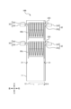
- Fig. 23 is a perspective view of the container erection device 10C according to the fourth embodiment.
- the container erection device 10C of this embodiment 4 differs from the container erection device 10 of embodiment 1 (see FIG. 2) in that the erection section 11 has a holding section 30 only at the insertion openings 21 of the steps other than the top step (i.e., the second step from the top and the first step from the bottom). Therefore, in this embodiment, the container erection device 10C has a fixed holding section 31 on the first step from the bottom and a movable holding section 32 on the second step from the top.
- Figures 24 to 26 are explanatory diagrams of the operation of the container installation device 10C.
- the container installation device 10C is in a state where the container 60 has not yet been installed.
- the user inserts container 60b into the second-highest insertion slot 21 (FIG. 24) and causes container 60b to be held by movable holding portion 32.
- container installation device 10C can guide the insertion of container 60a by using insertion port guide portion 22 provided at insertion port 21 so that container 60a avoids foreign matter prevention portion 72 of container 60b and is placed on top of container 60b.
- the container installation device 10C can interrupt and stack another container 60 (e.g., container 60c) on top of a container 60 (e.g., container 60b) that has already been installed on the movable holding section 32, in cases such as when an emergency inspection is to be performed, although this will disrupt the chronological order of the containers 60 to be used.
- container 60c e.g., container 60c
- container 60b e.g., container 60b
- This container erection device 10C can prevent the intrusion of foreign matter and improve the order of use of the containers 60. Moreover, since the upper movable holding unit 32 is omitted in the container erecting device 10C, the container erecting device 10C can be manufactured at a lower cost than the container erecting device 10 according to the first embodiment. In addition, the container erecting device 10C can be suitably used in the case of an operation in which the additionally erected container 60 is used with the highest priority, such as an emergency inspection, and when a discrepancy between the erection order and the use order can be tolerated.
- the present invention is not necessarily limited to having all of the components described.
- the present invention allows for certain components to be added to other components, or for some components to be changed to other components.
- the present invention allows for some components to be deleted.
Landscapes
- Chemical & Material Sciences (AREA)
- Health & Medical Sciences (AREA)
- Chemical Kinetics & Catalysis (AREA)
- Clinical Laboratory Science (AREA)
- General Health & Medical Sciences (AREA)
- Life Sciences & Earth Sciences (AREA)
- Analytical Chemistry (AREA)
- Biochemistry (AREA)
- Physics & Mathematics (AREA)
- General Physics & Mathematics (AREA)
- Immunology (AREA)
- Pathology (AREA)
- Details Of Rigid Or Semi-Rigid Containers (AREA)
- Passenger Equipment (AREA)
- Automatic Analysis And Handling Materials Therefor (AREA)
- Stackable Containers (AREA)
Abstract
Priority Applications (6)
| Application Number | Priority Date | Filing Date | Title |
|---|---|---|---|
| JP2025541221A JPWO2025041270A1 (fr) | 2023-08-22 | 2023-08-22 | |
| PCT/JP2023/030179 WO2025041270A1 (fr) | 2023-08-22 | 2023-08-22 | Appareil d'installation de récipient et récipient |
| KR1020257029849A KR20250141251A (ko) | 2023-08-22 | 2023-08-22 | 용기 가설 장치, 및, 용기 |
| CN202380095050.XA CN120813843A (zh) | 2023-08-22 | 2023-08-22 | 容器架设装置及容器 |
| TW113130922A TWI903699B (zh) | 2023-08-22 | 2024-08-16 | 容器架設裝置 |
| TW114125982A TW202540656A (zh) | 2023-08-22 | 2024-08-16 | 容器 |
Applications Claiming Priority (1)
| Application Number | Priority Date | Filing Date | Title |
|---|---|---|---|
| PCT/JP2023/030179 WO2025041270A1 (fr) | 2023-08-22 | 2023-08-22 | Appareil d'installation de récipient et récipient |
Publications (1)
| Publication Number | Publication Date |
|---|---|
| WO2025041270A1 true WO2025041270A1 (fr) | 2025-02-27 |
Family
ID=94731957
Family Applications (1)
| Application Number | Title | Priority Date | Filing Date |
|---|---|---|---|
| PCT/JP2023/030179 Pending WO2025041270A1 (fr) | 2023-08-22 | 2023-08-22 | Appareil d'installation de récipient et récipient |
Country Status (5)
| Country | Link |
|---|---|
| JP (1) | JPWO2025041270A1 (fr) |
| KR (1) | KR20250141251A (fr) |
| CN (1) | CN120813843A (fr) |
| TW (2) | TW202540656A (fr) |
| WO (1) | WO2025041270A1 (fr) |
Citations (6)
| Publication number | Priority date | Publication date | Assignee | Title |
|---|---|---|---|---|
| JP2003344431A (ja) * | 2002-05-17 | 2003-12-03 | Bionex Inc | 液体分配及び処理システム |
| JP2005249650A (ja) * | 2004-03-05 | 2005-09-15 | Matsushita Electric Ind Co Ltd | マイクロプレートの供給収納装置およびマイクロプレートの供給方法ならびに収納方法 |
| JP2014126392A (ja) * | 2012-12-25 | 2014-07-07 | Tosoh Corp | ノズルチップラックの供給装置 |
| WO2017163607A1 (fr) * | 2016-03-23 | 2017-09-28 | 株式会社 日立ハイテクノロジーズ | Dispositif d'analyse automatique |
| WO2020054033A1 (fr) * | 2018-09-13 | 2020-03-19 | 株式会社島津製作所 | Changeur de plaque pour échantillonneur automatique |
| JP2021039068A (ja) * | 2019-09-05 | 2021-03-11 | 株式会社柴崎製作所 | 検体希釈装置、検体集約装置、および検体希釈方法 |
Family Cites Families (4)
| Publication number | Priority date | Publication date | Assignee | Title |
|---|---|---|---|---|
| TWI249574B (en) * | 2002-11-19 | 2006-02-21 | Sanyo Electric Co | Preserving device |
| JP7221997B2 (ja) | 2018-06-29 | 2023-02-14 | エフ. ホフマン-ラ ロシュ エージー. | 自動分析器 |
| US12000848B2 (en) * | 2019-04-08 | 2024-06-04 | Molecular Devices, Llc | Incubation system and method for automated cell culture and testing |
| CN217779387U (zh) * | 2022-08-05 | 2022-11-11 | 江苏支点生物科技有限公司 | 一种酵母无细胞菌株消毒后保存用存放柜 |
-
2023
- 2023-08-22 JP JP2025541221A patent/JPWO2025041270A1/ja active Pending
- 2023-08-22 CN CN202380095050.XA patent/CN120813843A/zh active Pending
- 2023-08-22 WO PCT/JP2023/030179 patent/WO2025041270A1/fr active Pending
- 2023-08-22 KR KR1020257029849A patent/KR20250141251A/ko active Pending
-
2024
- 2024-08-16 TW TW114125982A patent/TW202540656A/zh unknown
- 2024-08-16 TW TW113130922A patent/TWI903699B/zh active
Patent Citations (6)
| Publication number | Priority date | Publication date | Assignee | Title |
|---|---|---|---|---|
| JP2003344431A (ja) * | 2002-05-17 | 2003-12-03 | Bionex Inc | 液体分配及び処理システム |
| JP2005249650A (ja) * | 2004-03-05 | 2005-09-15 | Matsushita Electric Ind Co Ltd | マイクロプレートの供給収納装置およびマイクロプレートの供給方法ならびに収納方法 |
| JP2014126392A (ja) * | 2012-12-25 | 2014-07-07 | Tosoh Corp | ノズルチップラックの供給装置 |
| WO2017163607A1 (fr) * | 2016-03-23 | 2017-09-28 | 株式会社 日立ハイテクノロジーズ | Dispositif d'analyse automatique |
| WO2020054033A1 (fr) * | 2018-09-13 | 2020-03-19 | 株式会社島津製作所 | Changeur de plaque pour échantillonneur automatique |
| JP2021039068A (ja) * | 2019-09-05 | 2021-03-11 | 株式会社柴崎製作所 | 検体希釈装置、検体集約装置、および検体希釈方法 |
Also Published As
| Publication number | Publication date |
|---|---|
| TW202509475A (zh) | 2025-03-01 |
| TW202540656A (zh) | 2025-10-16 |
| TWI903699B (zh) | 2025-11-01 |
| KR20250141251A (ko) | 2025-09-26 |
| JPWO2025041270A1 (fr) | 2025-02-27 |
| CN120813843A (zh) | 2025-10-17 |
Similar Documents
| Publication | Publication Date | Title |
|---|---|---|
| US9678093B2 (en) | Automatic analyzer | |
| US9025275B1 (en) | System for limiting access to internal environment of storage library via cartridge access port | |
| US8418881B2 (en) | Tissue cassette dispensing apparatus | |
| KR20090026127A (ko) | 캡 공급 장치 | |
| WO2025041270A1 (fr) | Appareil d'installation de récipient et récipient | |
| EP3690834A1 (fr) | Dispositif de distribution | |
| JP7199802B2 (ja) | 図書保管設置用のトレイ、及びトレイを備えた図書保管装置 | |
| CN102682528B (zh) | 自动售货机的商品搬出装置 | |
| JP7788719B2 (ja) | 薬剤供給装置 | |
| JP2017040513A (ja) | ノズルチップ供給装置 | |
| JP7822659B2 (ja) | 薬剤供給装置 | |
| JP7816742B2 (ja) | 薬剤供給装置 | |
| JP7807778B2 (ja) | 薬剤供給装置 | |
| JP7430401B2 (ja) | 物品収納容器および物品送出装置 | |
| JP7758327B2 (ja) | 薬剤供給装置 | |
| JP4936995B2 (ja) | 棒金収納装置 | |
| JP2025116261A (ja) | 薬剤供給装置 | |
| JP2017040512A (ja) | ノズルチップ供給装置 | |
| JP2006146688A (ja) | 自動販売機 | |
| US8982506B1 (en) | Multi-directional media element magazine retention | |
| JP2026020401A (ja) | 薬剤供給装置 | |
| HK1225100A1 (en) | Automatic analyzer | |
| HK1225100B (en) | Automatic analyzer | |
| WO2011151694A1 (fr) | Système d'éléments de support d'accès aléatoire pour alimenter des éléments de support | |
| JP2001155118A (ja) | カード収納装置 |
Legal Events
| Date | Code | Title | Description |
|---|---|---|---|
| 121 | Ep: the epo has been informed by wipo that ep was designated in this application |
Ref document number: 23949731 Country of ref document: EP Kind code of ref document: A1 |
|
| ENP | Entry into the national phase |
Ref document number: 2025541221 Country of ref document: JP Kind code of ref document: A |
|
| WWE | Wipo information: entry into national phase |
Ref document number: 2025541221 Country of ref document: JP |
|
| WWE | Wipo information: entry into national phase |
Ref document number: 202380095050.X Country of ref document: CN |
|
| WWP | Wipo information: published in national office |
Ref document number: 202380095050.X Country of ref document: CN |
|
| NENP | Non-entry into the national phase |
Ref country code: DE |